EP4484875A1 - Dispositif de refroidissement, dispositif de fabrication de semi-conducteurs et procédé de fabrication de semi-conducteurs - Google Patents
Dispositif de refroidissement, dispositif de fabrication de semi-conducteurs et procédé de fabrication de semi-conducteurs Download PDFInfo
- Publication number
- EP4484875A1 EP4484875A1 EP23823488.4A EP23823488A EP4484875A1 EP 4484875 A1 EP4484875 A1 EP 4484875A1 EP 23823488 A EP23823488 A EP 23823488A EP 4484875 A1 EP4484875 A1 EP 4484875A1
- Authority
- EP
- European Patent Office
- Prior art keywords
- refrigerant
- phase state
- cooling
- mixed
- liquid
- Prior art date
- Legal status (The legal status is an assumption and is not a legal conclusion. Google has not performed a legal analysis and makes no representation as to the accuracy of the status listed.)
- Pending
Links
Images


Classifications
-
- H—ELECTRICITY
- H10—SEMICONDUCTOR DEVICES; ELECTRIC SOLID-STATE DEVICES NOT OTHERWISE PROVIDED FOR
- H10P—GENERIC PROCESSES OR APPARATUS FOR THE MANUFACTURE OR TREATMENT OF DEVICES COVERED BY CLASS H10
- H10P72/00—Handling or holding of wafers, substrates or devices during manufacture or treatment thereof
- H10P72/04—Apparatus for manufacture or treatment
- H10P72/0431—Apparatus for thermal treatment
- H10P72/0434—Apparatus for thermal treatment mainly by convection
-
- F—MECHANICAL ENGINEERING; LIGHTING; HEATING; WEAPONS; BLASTING
- F25—REFRIGERATION OR COOLING; COMBINED HEATING AND REFRIGERATION SYSTEMS; HEAT PUMP SYSTEMS; MANUFACTURE OR STORAGE OF ICE; LIQUEFACTION SOLIDIFICATION OF GASES
- F25B—REFRIGERATION MACHINES, PLANTS OR SYSTEMS; COMBINED HEATING AND REFRIGERATION SYSTEMS; HEAT PUMP SYSTEMS
- F25B41/00—Fluid-circulation arrangements
- F25B41/40—Fluid line arrangements
-
- F—MECHANICAL ENGINEERING; LIGHTING; HEATING; WEAPONS; BLASTING
- F25—REFRIGERATION OR COOLING; COMBINED HEATING AND REFRIGERATION SYSTEMS; HEAT PUMP SYSTEMS; MANUFACTURE OR STORAGE OF ICE; LIQUEFACTION SOLIDIFICATION OF GASES
- F25B—REFRIGERATION MACHINES, PLANTS OR SYSTEMS; COMBINED HEATING AND REFRIGERATION SYSTEMS; HEAT PUMP SYSTEMS
- F25B1/00—Compression machines, plants or systems with non-reversible cycle
- F25B1/06—Compression machines, plants or systems with non-reversible cycle with compressor of jet type, e.g. using liquid under pressure
- F25B1/08—Compression machines, plants or systems with non-reversible cycle with compressor of jet type, e.g. using liquid under pressure using vapour under pressure
-
- F—MECHANICAL ENGINEERING; LIGHTING; HEATING; WEAPONS; BLASTING
- F25—REFRIGERATION OR COOLING; COMBINED HEATING AND REFRIGERATION SYSTEMS; HEAT PUMP SYSTEMS; MANUFACTURE OR STORAGE OF ICE; LIQUEFACTION SOLIDIFICATION OF GASES
- F25B—REFRIGERATION MACHINES, PLANTS OR SYSTEMS; COMBINED HEATING AND REFRIGERATION SYSTEMS; HEAT PUMP SYSTEMS
- F25B23/00—Machines, plants or systems, with a single mode of operation not covered by groups F25B1/00 - F25B21/00, e.g. using selective radiation effect
- F25B23/006—Machines, plants or systems, with a single mode of operation not covered by groups F25B1/00 - F25B21/00, e.g. using selective radiation effect boiling cooling systems
-
- F—MECHANICAL ENGINEERING; LIGHTING; HEATING; WEAPONS; BLASTING
- F25—REFRIGERATION OR COOLING; COMBINED HEATING AND REFRIGERATION SYSTEMS; HEAT PUMP SYSTEMS; MANUFACTURE OR STORAGE OF ICE; LIQUEFACTION SOLIDIFICATION OF GASES
- F25B—REFRIGERATION MACHINES, PLANTS OR SYSTEMS; COMBINED HEATING AND REFRIGERATION SYSTEMS; HEAT PUMP SYSTEMS
- F25B25/00—Machines, plants or systems, using a combination of modes of operation covered by two or more of the groups F25B1/00 - F25B23/00
- F25B25/005—Machines, plants or systems, using a combination of modes of operation covered by two or more of the groups F25B1/00 - F25B23/00 using primary and secondary systems
-
- F—MECHANICAL ENGINEERING; LIGHTING; HEATING; WEAPONS; BLASTING
- F25—REFRIGERATION OR COOLING; COMBINED HEATING AND REFRIGERATION SYSTEMS; HEAT PUMP SYSTEMS; MANUFACTURE OR STORAGE OF ICE; LIQUEFACTION SOLIDIFICATION OF GASES
- F25B—REFRIGERATION MACHINES, PLANTS OR SYSTEMS; COMBINED HEATING AND REFRIGERATION SYSTEMS; HEAT PUMP SYSTEMS
- F25B39/00—Evaporators; Condensers
- F25B39/02—Evaporators
- F25B39/028—Evaporators having distributing means
-
- F—MECHANICAL ENGINEERING; LIGHTING; HEATING; WEAPONS; BLASTING
- F25—REFRIGERATION OR COOLING; COMBINED HEATING AND REFRIGERATION SYSTEMS; HEAT PUMP SYSTEMS; MANUFACTURE OR STORAGE OF ICE; LIQUEFACTION SOLIDIFICATION OF GASES
- F25B—REFRIGERATION MACHINES, PLANTS OR SYSTEMS; COMBINED HEATING AND REFRIGERATION SYSTEMS; HEAT PUMP SYSTEMS
- F25B39/00—Evaporators; Condensers
- F25B39/04—Condensers
-
- F—MECHANICAL ENGINEERING; LIGHTING; HEATING; WEAPONS; BLASTING
- F25—REFRIGERATION OR COOLING; COMBINED HEATING AND REFRIGERATION SYSTEMS; HEAT PUMP SYSTEMS; MANUFACTURE OR STORAGE OF ICE; LIQUEFACTION SOLIDIFICATION OF GASES
- F25B—REFRIGERATION MACHINES, PLANTS OR SYSTEMS; COMBINED HEATING AND REFRIGERATION SYSTEMS; HEAT PUMP SYSTEMS
- F25B41/00—Fluid-circulation arrangements
- F25B41/20—Disposition of valves, e.g. of on-off valves or flow control valves
- F25B41/22—Disposition of valves, e.g. of on-off valves or flow control valves between evaporator and compressor
-
- F—MECHANICAL ENGINEERING; LIGHTING; HEATING; WEAPONS; BLASTING
- F25—REFRIGERATION OR COOLING; COMBINED HEATING AND REFRIGERATION SYSTEMS; HEAT PUMP SYSTEMS; MANUFACTURE OR STORAGE OF ICE; LIQUEFACTION SOLIDIFICATION OF GASES
- F25B—REFRIGERATION MACHINES, PLANTS OR SYSTEMS; COMBINED HEATING AND REFRIGERATION SYSTEMS; HEAT PUMP SYSTEMS
- F25B41/00—Fluid-circulation arrangements
- F25B41/40—Fluid line arrangements
- F25B41/42—Arrangements for diverging or converging flows, e.g. branch lines or junctions
- F25B41/48—Arrangements for diverging or converging flows, e.g. branch lines or junctions for flow path resistance control on the downstream side of the diverging point, e.g. by an orifice
-
- F—MECHANICAL ENGINEERING; LIGHTING; HEATING; WEAPONS; BLASTING
- F25—REFRIGERATION OR COOLING; COMBINED HEATING AND REFRIGERATION SYSTEMS; HEAT PUMP SYSTEMS; MANUFACTURE OR STORAGE OF ICE; LIQUEFACTION SOLIDIFICATION OF GASES
- F25B—REFRIGERATION MACHINES, PLANTS OR SYSTEMS; COMBINED HEATING AND REFRIGERATION SYSTEMS; HEAT PUMP SYSTEMS
- F25B5/00—Compression machines, plants or systems, with several evaporator circuits, e.g. for varying refrigerating capacity
- F25B5/04—Compression machines, plants or systems, with several evaporator circuits, e.g. for varying refrigerating capacity arranged in series
-
- F—MECHANICAL ENGINEERING; LIGHTING; HEATING; WEAPONS; BLASTING
- F25—REFRIGERATION OR COOLING; COMBINED HEATING AND REFRIGERATION SYSTEMS; HEAT PUMP SYSTEMS; MANUFACTURE OR STORAGE OF ICE; LIQUEFACTION SOLIDIFICATION OF GASES
- F25B—REFRIGERATION MACHINES, PLANTS OR SYSTEMS; COMBINED HEATING AND REFRIGERATION SYSTEMS; HEAT PUMP SYSTEMS
- F25B9/00—Compression machines, plants or systems, in which the refrigerant is air or other gas of low boiling point
- F25B9/002—Compression machines, plants or systems, in which the refrigerant is air or other gas of low boiling point characterised by the refrigerant
- F25B9/006—Compression machines, plants or systems, in which the refrigerant is air or other gas of low boiling point characterised by the refrigerant the refrigerant containing more than one component
-
- F—MECHANICAL ENGINEERING; LIGHTING; HEATING; WEAPONS; BLASTING
- F28—HEAT EXCHANGE IN GENERAL
- F28D—HEAT-EXCHANGE APPARATUS, NOT PROVIDED FOR IN ANOTHER SUBCLASS, IN WHICH THE HEAT-EXCHANGE MEDIA DO NOT COME INTO DIRECT CONTACT
- F28D15/00—Heat-exchange apparatus with the intermediate heat-transfer medium in closed tubes passing into or through the conduit walls ; Heat-exchange apparatus employing intermediate heat-transfer medium or bodies
- F28D15/02—Heat-exchange apparatus with the intermediate heat-transfer medium in closed tubes passing into or through the conduit walls ; Heat-exchange apparatus employing intermediate heat-transfer medium or bodies in which the medium condenses and evaporates, e.g. heat pipes
- F28D15/0266—Heat-exchange apparatus with the intermediate heat-transfer medium in closed tubes passing into or through the conduit walls ; Heat-exchange apparatus employing intermediate heat-transfer medium or bodies in which the medium condenses and evaporates, e.g. heat pipes with separate evaporating and condensing chambers connected by at least one conduit; Loop-type heat pipes; with multiple or common evaporating or condensing chambers
-
- G—PHYSICS
- G03—PHOTOGRAPHY; CINEMATOGRAPHY; ANALOGOUS TECHNIQUES USING WAVES OTHER THAN OPTICAL WAVES; ELECTROGRAPHY; HOLOGRAPHY
- G03F—PHOTOMECHANICAL PRODUCTION OF TEXTURED OR PATTERNED SURFACES, e.g. FOR PRINTING, FOR PROCESSING OF SEMICONDUCTOR DEVICES; MATERIALS THEREFOR; ORIGINALS THEREFOR; APPARATUS SPECIALLY ADAPTED THEREFOR
- G03F7/00—Photomechanical, e.g. photolithographic, production of textured or patterned surfaces, e.g. printing surfaces; Materials therefor, e.g. comprising photoresists; Apparatus specially adapted therefor
- G03F7/20—Exposure; Apparatus therefor
- G03F7/2041—Exposure; Apparatus therefor in the presence of a fluid, e.g. immersion; using fluid cooling means
-
- F—MECHANICAL ENGINEERING; LIGHTING; HEATING; WEAPONS; BLASTING
- F25—REFRIGERATION OR COOLING; COMBINED HEATING AND REFRIGERATION SYSTEMS; HEAT PUMP SYSTEMS; MANUFACTURE OR STORAGE OF ICE; LIQUEFACTION SOLIDIFICATION OF GASES
- F25B—REFRIGERATION MACHINES, PLANTS OR SYSTEMS; COMBINED HEATING AND REFRIGERATION SYSTEMS; HEAT PUMP SYSTEMS
- F25B2339/00—Details of evaporators; Details of condensers
- F25B2339/02—Details of evaporators
- F25B2339/024—Evaporators with refrigerant in a vessel in which is situated a heat exchanger
-
- F—MECHANICAL ENGINEERING; LIGHTING; HEATING; WEAPONS; BLASTING
- F25—REFRIGERATION OR COOLING; COMBINED HEATING AND REFRIGERATION SYSTEMS; HEAT PUMP SYSTEMS; MANUFACTURE OR STORAGE OF ICE; LIQUEFACTION SOLIDIFICATION OF GASES
- F25B—REFRIGERATION MACHINES, PLANTS OR SYSTEMS; COMBINED HEATING AND REFRIGERATION SYSTEMS; HEAT PUMP SYSTEMS
- F25B2400/00—General features or devices for refrigeration machines, plants or systems, combined heating and refrigeration systems or heat-pump systems, i.e. not limited to a particular subgroup of F25B
- F25B2400/01—Heaters
-
- F—MECHANICAL ENGINEERING; LIGHTING; HEATING; WEAPONS; BLASTING
- F25—REFRIGERATION OR COOLING; COMBINED HEATING AND REFRIGERATION SYSTEMS; HEAT PUMP SYSTEMS; MANUFACTURE OR STORAGE OF ICE; LIQUEFACTION SOLIDIFICATION OF GASES
- F25B—REFRIGERATION MACHINES, PLANTS OR SYSTEMS; COMBINED HEATING AND REFRIGERATION SYSTEMS; HEAT PUMP SYSTEMS
- F25B2400/00—General features or devices for refrigeration machines, plants or systems, combined heating and refrigeration systems or heat-pump systems, i.e. not limited to a particular subgroup of F25B
- F25B2400/04—Refrigeration circuit bypassing means
- F25B2400/0403—Refrigeration circuit bypassing means for the condenser
-
- F—MECHANICAL ENGINEERING; LIGHTING; HEATING; WEAPONS; BLASTING
- F25—REFRIGERATION OR COOLING; COMBINED HEATING AND REFRIGERATION SYSTEMS; HEAT PUMP SYSTEMS; MANUFACTURE OR STORAGE OF ICE; LIQUEFACTION SOLIDIFICATION OF GASES
- F25B—REFRIGERATION MACHINES, PLANTS OR SYSTEMS; COMBINED HEATING AND REFRIGERATION SYSTEMS; HEAT PUMP SYSTEMS
- F25B2400/00—General features or devices for refrigeration machines, plants or systems, combined heating and refrigeration systems or heat-pump systems, i.e. not limited to a particular subgroup of F25B
- F25B2400/04—Refrigeration circuit bypassing means
- F25B2400/0409—Refrigeration circuit bypassing means for the evaporator
-
- F—MECHANICAL ENGINEERING; LIGHTING; HEATING; WEAPONS; BLASTING
- F25—REFRIGERATION OR COOLING; COMBINED HEATING AND REFRIGERATION SYSTEMS; HEAT PUMP SYSTEMS; MANUFACTURE OR STORAGE OF ICE; LIQUEFACTION SOLIDIFICATION OF GASES
- F25B—REFRIGERATION MACHINES, PLANTS OR SYSTEMS; COMBINED HEATING AND REFRIGERATION SYSTEMS; HEAT PUMP SYSTEMS
- F25B2400/00—General features or devices for refrigeration machines, plants or systems, combined heating and refrigeration systems or heat-pump systems, i.e. not limited to a particular subgroup of F25B
- F25B2400/04—Refrigeration circuit bypassing means
- F25B2400/0411—Refrigeration circuit bypassing means for the expansion valve or capillary tube
-
- F—MECHANICAL ENGINEERING; LIGHTING; HEATING; WEAPONS; BLASTING
- F25—REFRIGERATION OR COOLING; COMBINED HEATING AND REFRIGERATION SYSTEMS; HEAT PUMP SYSTEMS; MANUFACTURE OR STORAGE OF ICE; LIQUEFACTION SOLIDIFICATION OF GASES
- F25B—REFRIGERATION MACHINES, PLANTS OR SYSTEMS; COMBINED HEATING AND REFRIGERATION SYSTEMS; HEAT PUMP SYSTEMS
- F25B2400/00—General features or devices for refrigeration machines, plants or systems, combined heating and refrigeration systems or heat-pump systems, i.e. not limited to a particular subgroup of F25B
- F25B2400/05—Compression system with heat exchange between particular parts of the system
- F25B2400/054—Compression system with heat exchange between particular parts of the system between the suction tube of the compressor and another part of the cycle
-
- F—MECHANICAL ENGINEERING; LIGHTING; HEATING; WEAPONS; BLASTING
- F25—REFRIGERATION OR COOLING; COMBINED HEATING AND REFRIGERATION SYSTEMS; HEAT PUMP SYSTEMS; MANUFACTURE OR STORAGE OF ICE; LIQUEFACTION SOLIDIFICATION OF GASES
- F25B—REFRIGERATION MACHINES, PLANTS OR SYSTEMS; COMBINED HEATING AND REFRIGERATION SYSTEMS; HEAT PUMP SYSTEMS
- F25B2400/00—General features or devices for refrigeration machines, plants or systems, combined heating and refrigeration systems or heat-pump systems, i.e. not limited to a particular subgroup of F25B
- F25B2400/12—Inflammable refrigerants
- F25B2400/121—Inflammable refrigerants using R1234
-
- F—MECHANICAL ENGINEERING; LIGHTING; HEATING; WEAPONS; BLASTING
- F25—REFRIGERATION OR COOLING; COMBINED HEATING AND REFRIGERATION SYSTEMS; HEAT PUMP SYSTEMS; MANUFACTURE OR STORAGE OF ICE; LIQUEFACTION SOLIDIFICATION OF GASES
- F25B—REFRIGERATION MACHINES, PLANTS OR SYSTEMS; COMBINED HEATING AND REFRIGERATION SYSTEMS; HEAT PUMP SYSTEMS
- F25B2400/00—General features or devices for refrigeration machines, plants or systems, combined heating and refrigeration systems or heat-pump systems, i.e. not limited to a particular subgroup of F25B
- F25B2400/17—Re-condensers
-
- F—MECHANICAL ENGINEERING; LIGHTING; HEATING; WEAPONS; BLASTING
- F25—REFRIGERATION OR COOLING; COMBINED HEATING AND REFRIGERATION SYSTEMS; HEAT PUMP SYSTEMS; MANUFACTURE OR STORAGE OF ICE; LIQUEFACTION SOLIDIFICATION OF GASES
- F25B—REFRIGERATION MACHINES, PLANTS OR SYSTEMS; COMBINED HEATING AND REFRIGERATION SYSTEMS; HEAT PUMP SYSTEMS
- F25B2400/00—General features or devices for refrigeration machines, plants or systems, combined heating and refrigeration systems or heat-pump systems, i.e. not limited to a particular subgroup of F25B
- F25B2400/23—Separators
-
- F—MECHANICAL ENGINEERING; LIGHTING; HEATING; WEAPONS; BLASTING
- F25—REFRIGERATION OR COOLING; COMBINED HEATING AND REFRIGERATION SYSTEMS; HEAT PUMP SYSTEMS; MANUFACTURE OR STORAGE OF ICE; LIQUEFACTION SOLIDIFICATION OF GASES
- F25B—REFRIGERATION MACHINES, PLANTS OR SYSTEMS; COMBINED HEATING AND REFRIGERATION SYSTEMS; HEAT PUMP SYSTEMS
- F25B2500/00—Problems to be solved
- F25B2500/07—Exceeding a certain pressure value in a refrigeration component or cycle
-
- F—MECHANICAL ENGINEERING; LIGHTING; HEATING; WEAPONS; BLASTING
- F25—REFRIGERATION OR COOLING; COMBINED HEATING AND REFRIGERATION SYSTEMS; HEAT PUMP SYSTEMS; MANUFACTURE OR STORAGE OF ICE; LIQUEFACTION SOLIDIFICATION OF GASES
- F25B—REFRIGERATION MACHINES, PLANTS OR SYSTEMS; COMBINED HEATING AND REFRIGERATION SYSTEMS; HEAT PUMP SYSTEMS
- F25B2500/00—Problems to be solved
- F25B2500/28—Means for preventing liquid refrigerant entering into the compressor
-
- F—MECHANICAL ENGINEERING; LIGHTING; HEATING; WEAPONS; BLASTING
- F25—REFRIGERATION OR COOLING; COMBINED HEATING AND REFRIGERATION SYSTEMS; HEAT PUMP SYSTEMS; MANUFACTURE OR STORAGE OF ICE; LIQUEFACTION SOLIDIFICATION OF GASES
- F25B—REFRIGERATION MACHINES, PLANTS OR SYSTEMS; COMBINED HEATING AND REFRIGERATION SYSTEMS; HEAT PUMP SYSTEMS
- F25B2600/00—Control issues
- F25B2600/02—Compressor control
- F25B2600/021—Inverters therefor
-
- F—MECHANICAL ENGINEERING; LIGHTING; HEATING; WEAPONS; BLASTING
- F25—REFRIGERATION OR COOLING; COMBINED HEATING AND REFRIGERATION SYSTEMS; HEAT PUMP SYSTEMS; MANUFACTURE OR STORAGE OF ICE; LIQUEFACTION SOLIDIFICATION OF GASES
- F25B—REFRIGERATION MACHINES, PLANTS OR SYSTEMS; COMBINED HEATING AND REFRIGERATION SYSTEMS; HEAT PUMP SYSTEMS
- F25B2600/00—Control issues
- F25B2600/25—Control of valves
- F25B2600/2507—Flow-diverting valves
-
- F—MECHANICAL ENGINEERING; LIGHTING; HEATING; WEAPONS; BLASTING
- F25—REFRIGERATION OR COOLING; COMBINED HEATING AND REFRIGERATION SYSTEMS; HEAT PUMP SYSTEMS; MANUFACTURE OR STORAGE OF ICE; LIQUEFACTION SOLIDIFICATION OF GASES
- F25B—REFRIGERATION MACHINES, PLANTS OR SYSTEMS; COMBINED HEATING AND REFRIGERATION SYSTEMS; HEAT PUMP SYSTEMS
- F25B2600/00—Control issues
- F25B2600/25—Control of valves
- F25B2600/2513—Expansion valves
-
- F—MECHANICAL ENGINEERING; LIGHTING; HEATING; WEAPONS; BLASTING
- F25—REFRIGERATION OR COOLING; COMBINED HEATING AND REFRIGERATION SYSTEMS; HEAT PUMP SYSTEMS; MANUFACTURE OR STORAGE OF ICE; LIQUEFACTION SOLIDIFICATION OF GASES
- F25B—REFRIGERATION MACHINES, PLANTS OR SYSTEMS; COMBINED HEATING AND REFRIGERATION SYSTEMS; HEAT PUMP SYSTEMS
- F25B2700/00—Sensing or detecting of parameters; Sensors therefor
- F25B2700/13—Mass flow of refrigerants
-
- F—MECHANICAL ENGINEERING; LIGHTING; HEATING; WEAPONS; BLASTING
- F25—REFRIGERATION OR COOLING; COMBINED HEATING AND REFRIGERATION SYSTEMS; HEAT PUMP SYSTEMS; MANUFACTURE OR STORAGE OF ICE; LIQUEFACTION SOLIDIFICATION OF GASES
- F25B—REFRIGERATION MACHINES, PLANTS OR SYSTEMS; COMBINED HEATING AND REFRIGERATION SYSTEMS; HEAT PUMP SYSTEMS
- F25B2700/00—Sensing or detecting of parameters; Sensors therefor
- F25B2700/19—Pressures
- F25B2700/197—Pressures of the evaporator
-
- F—MECHANICAL ENGINEERING; LIGHTING; HEATING; WEAPONS; BLASTING
- F25—REFRIGERATION OR COOLING; COMBINED HEATING AND REFRIGERATION SYSTEMS; HEAT PUMP SYSTEMS; MANUFACTURE OR STORAGE OF ICE; LIQUEFACTION SOLIDIFICATION OF GASES
- F25B—REFRIGERATION MACHINES, PLANTS OR SYSTEMS; COMBINED HEATING AND REFRIGERATION SYSTEMS; HEAT PUMP SYSTEMS
- F25B2700/00—Sensing or detecting of parameters; Sensors therefor
- F25B2700/21—Temperatures
- F25B2700/2117—Temperatures of an evaporator
- F25B2700/21174—Temperatures of an evaporator of the refrigerant at the inlet of the evaporator
-
- F—MECHANICAL ENGINEERING; LIGHTING; HEATING; WEAPONS; BLASTING
- F28—HEAT EXCHANGE IN GENERAL
- F28D—HEAT-EXCHANGE APPARATUS, NOT PROVIDED FOR IN ANOTHER SUBCLASS, IN WHICH THE HEAT-EXCHANGE MEDIA DO NOT COME INTO DIRECT CONTACT
- F28D15/00—Heat-exchange apparatus with the intermediate heat-transfer medium in closed tubes passing into or through the conduit walls ; Heat-exchange apparatus employing intermediate heat-transfer medium or bodies
- F28D15/02—Heat-exchange apparatus with the intermediate heat-transfer medium in closed tubes passing into or through the conduit walls ; Heat-exchange apparatus employing intermediate heat-transfer medium or bodies in which the medium condenses and evaporates, e.g. heat pipes
- F28D2015/0291—Heat-exchange apparatus with the intermediate heat-transfer medium in closed tubes passing into or through the conduit walls ; Heat-exchange apparatus employing intermediate heat-transfer medium or bodies in which the medium condenses and evaporates, e.g. heat pipes comprising internal rotor means, e.g. turbine driven by the working fluid
Definitions
- the present invention relates to a cooling device, a semiconductor manufacturing apparatus and a semiconductor manufacturing method.
- a semiconductor manufacturing apparatus such as a pattern forming apparatus such as an exposure apparatus, an imprint apparatus, or an electron beam lithography apparatus or a plasma processing apparatus such as a CVD apparatus, an etching apparatus, or a sputtering apparatus includes a driving mechanism or a heat generating portion such as a member that is heated by plasma.
- the semiconductor manufacturing apparatus includes a cooling device. The cooling device cools the heat generating portion by taking heat from the heat generating portion and exhausting the heat outside the apparatus.
- PTL 1 discloses a cooling system including an evaporator that extracts heat from a component, a condenser, a pump, an accumulator, a heat exchanger, and a temperature sensor.
- a circulation path is constituted to return a fluid refrigerant from the pump via the evaporator and the condenser to the pump, and the accumulator communicates the fluid to the circulation path.
- the heat exchanger transfers heat from the fluid refrigerant in the accumulator and transfers heat to the fluid refrigerant in the accumulator. At this time, the amount of transferred heat is controlled based on an output from the temperature sensor.
- a cooling system that circulates a liquid refrigerant by a pump often adopts a refrigerant (for example, HFO-1336mzz(E), Novec7000, or HFO-1233zd(Z)) with an atmospheric boiling point equal to or higher than room temperature, which does not require a liquefying means.
- a refrigerant for example, HFO-1336mzz(E), Novec7000, or HFO-1233zd(Z)
- a vapor pressure is lower than the atmospheric pressure.
- a linear motor having a jacket structure in which a coil is arranged in a closed container and is cooled by filling the internal space with a fluid refrigerant, the boiled vaporized refrigerant flows through an upper part of the internal space of the jacket due to a density difference.
- the vaporized refrigerant occupies the internal space of the jacket, thereby causing a state in which the upper portion of the coil as a heat generating portion is covered with the vaporized refrigerant and cannot be ebullient-cooled, that is, dryout. If dryout occurs, the temperature of the coil suddenly rises, and the coil is burned out.
- the present invention provides a cooling device advantageous in cooling a cooling target.
- a cooling device as one aspect of the present invention is that a cooling device for cooling a cooling target, characterized by including a circulation system configured to circulate a refrigerant for cooling the cooling target, wherein a container including a region where heat is exchanged between the refrigerant and at least a part of the cooling target is provided in the circulation system, the refrigerant is a mixed refrigerant obtained by mixing a first refrigerant of a first boiling point and a second refrigerant of a second boiling point higher than the first boiling point, the circulation system circulates the mixed refrigerant so that the mixed refrigerant enters the container at a predetermined temperature, and the first refrigerant has a vapor pressure higher than a pressure resistance of the container at the predetermined temperature.
- a cooling device advantageous in cooling a cooling target is provided.
- the heat exchange container 25 includes a heat exchange region 252 that exchanges heat with the cooling target 80, and incorporates the cooling target 80 in the heat exchange region 252.
- the cooling target 80 incorporated in the heat exchange container 25 generates heat
- the low boiling point refrigerant 11 of the liquid refrigerant 14 (mixed refrigerant) supplied to the heat exchange container 25 boils to cool the cooling target 80 by latent heat of vaporization, and the high boiling point refrigerant 12 convection-cools the cooling target 80.
- the low boiling point refrigerant 11 ebullient-cools the cooling target 80 to enter the vapor phase state in the heat exchange region 252 in the heat exchange container, and the high boiling point refrigerant 12 convection-cools the cooling target 80 in the liquid phase state in the heat exchange region 252 in the heat exchange container.
- the low boiling point refrigerant 11 that passes through the heat exchange region 252 in the heat exchange container and is discharged from the heat exchange container 25 enters the liquid phase state or the gas-liquid mixed phase (two-phase) state in accordance with the heat generation state of the cooling target 80.
- the high boiling point refrigerant 12 that passes through the heat exchange region 252 in the heat exchange container and is discharged from the heat exchange container 25 is always maintained in the liquid phase state regardless of the heat generation state of the cooling target 80.
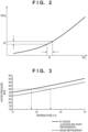
- a pressure sensor 26 is provided on the downstream side of the expansion valve 24, and an opening of the expansion valve 24 is controlled so that the pressure of the heat exchange container 25 (the pressure detected by the pressure sensor 26) is always close to the vapor pressure of the low boiling point refrigerant 11.
- the refrigerant discharged from the heat exchange container 25 always includes the liquid refrigerant 14. Therefore, if the refrigerant discharged from the heat exchange container 25 is directly returned to the compressor 22, the compressor 22 cannot compress the refrigerant in the liquid phase state, and is thus damaged.
- the gas refrigerant 13 separated by the gas-liquid separation portion 27 is directly returned to the compressor 22 through the second path 212, and the liquid refrigerant 14 separated by the gas-liquid separation portion 27 is sent to the first vaporizer 28 before being returned to the compressor 22.
- the first vaporizer 28 causes a high-temperature gas refrigerant 15 on the downstream side of the compressor 22 to branch before returning it to the condenser 23 and merge with the liquid refrigerant 14 separated by the gas-liquid separation portion 27, and vaporizes the liquid refrigerant 14 by the high-temperature gas refrigerant 15 to return to the compressor 22.
- the first vaporizer 28 includes a flow rate sensor 29 that detects the flow rate of the liquid refrigerant 14, a throttle valve 30 that adjusts the flow rate of the high-temperature gas refrigerant 15, and a flow rate controller 31.
- the flow rate controller 31 controls the throttle valve 30 based on the flow rate of the liquid refrigerant 14 detected by the flow rate sensor 29 so that the flow rate of the high-temperature gas refrigerant 15 made to merge with the liquid refrigerant 14 becomes a flow rate necessary to vaporize the liquid refrigerant 14.
- the first vaporizer 28 vaporizes the liquid refrigerant 14 by making a part of the gas refrigerant 15 (the mixed refrigerant in the vapor phase state) sent from the compressor 22 merge, via the throttle valve 30, with the liquid refrigerant 14 separated by the gas-liquid separation portion 27.
- an ultrasonic sensor is suitable as the flow rate sensor 29 but the present invention is not limited to this.
- An increase in flow rate of the liquid refrigerant 14 included in the refrigerant discharged from the heat exchange container 25 indicates a decrease in heat generation amount of the cooling target 80 incorporated in the heat exchange container 25, thereby making it possible to decrease the flow rate of the liquid refrigerant 14 to be supplied to the heat exchange container 25.
- the flow rate controller 31 controls the opening of the throttle valve 30 while controlling (throttling) the opening of the expansion valve 24, thereby properly controlling the flow rate balance between the liquid refrigerant 14 separated by the gas-liquid separation portion 27 and the high-temperature gas refrigerant 15 from the compressor 22. Furthermore, the flow rate controller 31 may control the compression capability (the total flow rate of the refrigerant) of the compressor 22 via an inverter 32. This can prevent the liquid refrigerant 14 from returning to the compressor 22, and maintain the refrigeration cycle following the variation of a heat load.
- the cooling device CA2 applied to the general refrigeration cycle.
- the cooling device CA1 according to the first embodiment in a case where the heat exchange container 7 recovers a large heat amount and the condenser 2 exhausts heat, two circulation systems via different refrigeration cycles are necessary.
- the cooling device CA2 according to this embodiment it is possible to exhaust heat by one circulation system. Therefore, it is possible to provide the cooling device CA2 that contributes to space saving and energy saving.
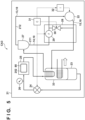
- Fig. 5 is a schematic circuit diagram showing the arrangement of a cooling device CA3 according to the third embodiment of the present invention.
- the cooling device CA3 according to this embodiment is obtained by improving the cooling device CA2 of the second embodiment. Note that matters not mentioned in this embodiment are the same as in the second embodiment.
- a second vaporizer 33 that vaporizes a refrigerant (mixed refrigerant) in the gas-liquid mixed phase state discharged from a heat exchange container 25 is newly provided between the heat exchange container 25 and a gas-liquid separation portion 27.
- the second vaporizer 33 is implemented as, for example, a heat exchanger that is provided in a condenser 23 and exchanges heat between a high-temperature gas refrigerant 15 (a mixed refrigerant in the vapor phase state) sent from a compressor 22 and a refrigerant (mixed refrigerant) in the gas-liquid mixed phase state discharged from the heat exchange container 25.
- a liquid refrigerant 14 included in the refrigerant discharged from the heat exchange container 25 is heated by the high-temperature gas refrigerant 15 in the second vaporizer 33, and partially vaporizes.
- the high-temperature gas refrigerant 15 is cooled by latent heat of vaporization of the liquid refrigerant 14, and partially condenses.
- the condenser 23 since the condenser 23 partially condenses the high-temperature gas refrigerant 15 sent from the compressor 22 by the liquid refrigerant 14 discharged from the heat exchange container 25, it is possible to reduce the exhaust heat amount outside the system.
- the condenser 23 by providing two vaporizers of the first vaporizer 28 and the second vaporizer 33, it is possible to further reduce the risk of damage of the compressor 22 caused by mixing of the liquid refrigerant 14.
- FIGs. 6A , 6B , and 6C are schematic circuit diagrams each showing the arrangement of a cooling device according to the fourth embodiment of the present invention.
- Each of the first to third embodiments is limited to cooling of the cooling target 80 incorporated in the heat exchange container 7 or 25.
- many cooling targets exist in addition to the cooling target 80.
- a refrigerant that does not vaporize in the heat exchange container 7 or 25 or the liquid refrigerant 14 separated by the gas-liquid separation portion 27 is in the liquid phase state, and thus has a capability of ebullient-cooling the cooling target.
- a new path for cooling another cooling target (a cooling target different from a cooling target 80) not incorporated in a heat exchange container 7 or 25 is formed.
- Fig. 6A shows a case where a path for cooling a cooling target 81 different from the cooling target 80 is formed in the cooling device CA1 of the first embodiment.
- the cooling device CA1 includes a heat exchanger 34 on the downstream side of the heat exchange container 7.
- the heat exchanger 34 thermally contacts the cooling target 81, and exchanges heat between the cooling target 81 and a refrigerant (mixed refrigerant) in the gas-liquid mixed phase state discharged from the heat exchange container 7, thereby cooling the cooling target 81.
- a liquid refrigerant 14 that does not vaporize in the heat exchange container 7 boils by taking heat from the cooling target 81, thereby ebullient-cooling the cooling target 81.
- the refrigerant having passed through the heat exchanger 34 is returned in the gas-liquid mixed phase state to the condenser 2, is cooled by the condenser 2 to change in phase, and is then recirculated as the liquid refrigerant 14.
- Fig. 6B shows a case where a path for cooling the cooling target 81 different from the cooling target 80 is formed in the cooling device CA2 of the second embodiment.
- the cooling device CA2 includes the heat exchanger 34 in a first path 211 through which the liquid refrigerant 14 separated by a gas-liquid separation portion 27 on the downstream side of the heat exchange container 25 flows.
- the heat exchanger 34 thermally contacts the cooling target 81, and exchanges heat between the cooling target 81 and the liquid refrigerant 14 separated by the gas-liquid separation portion 27, thereby cooling the cooling target 81.
- the liquid refrigerant 14 separated by the gas-liquid separation portion 27 boils by taking heat from the cooling target 81, thereby ebullient-cooling the cooling target 81.
- the refrigerant having passed through the heat exchanger 34 is sent in the vapor phase state or the gas-liquid mixed phase state to a first vaporizer 28, completely vaporizes in the first vaporizer 28, and is returned as a gas refrigerant 13 to a compressor 22 to be recirculated.
- Fig. 6C shows a case where a path for cooling the cooling target 81 different from the cooling target 80 is formed in the cooling device CA3 of the third embodiment.
- the first path 211 through which the liquid refrigerant 14 separated by the gas-liquid separation portion 27 flows branches into a third path 213 and a fourth path 214.
- the third path 213 is a path to a second vaporizer 33 via an expansion valve 35 and the heat exchanger 34
- the fourth path 214 is a path to the second vaporizer 33 via a throttle valve 36.
- the pressure of the liquid refrigerant 14 is adjusted to a predetermined vapor pressure via the expansion valve 35.
- a semiconductor manufacturing apparatus to which a cooling device CA1, CA2, or CA3 is applicable and in this embodiment, a semiconductor manufacturing apparatus to which the cooling device CA1 is applied will exemplarily be described below with reference to Figs. 7, 8 , and 9 .
- Fig. 7 is a schematic view showing the arrangement of a semiconductor manufacturing apparatus, and more specifically, the arrangement of an exposure apparatus 100 as an example of a pattern forming apparatus.
- the exposure apparatus 100 is configured to transfer a pattern of an original 101 through a projection optical system 140 to a photosensitive layer supplied (applied) to a substrate 102.
- the exposure apparatus 100 includes an illumination optical system 150 that illuminates the original 101, the projection optical system 140, a substrate positioning mechanism SPM that positions the substrate 102, and an original positioning mechanism (not shown) that positions the original 101.
- the substrate positioning mechanism SPM includes a substrate stage 110 that supports a substrate chuck holding the substrate 102, a driving mechanism 120 that drives the substrate stage 110, and a base member 130 that supports the driving mechanism 120.
- the driving mechanism 120 includes an actuator including a mover 122 that moves together with the substrate stage 110 and a stator 124 fixed to the base member 130.
- the stator 124 includes a coil (coil line) as the cooling target 80 of the cooling device CA1.
- the cooling device CA1 is configured to cool the coil of the stator 124 serving as the cooling target 80.
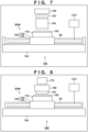
- Fig. 8 is a schematic view showing the arrangement of a semiconductor manufacturing apparatus, and more specifically, the arrangement of an imprint apparatus 200 as an example of a pattern forming apparatus.
- the imprint apparatus 200 is configured to transfer the pattern of the original 101 (mold) to an imprint material arranged on (supplied to) the substrate 102.
- the imprint apparatus 200 includes an original driving mechanism 160 that drives the original 101, the substrate positioning mechanism SPM that drives the substrate 102, and a curing unit 170 that cures the imprint material arranged on the substrate 102.
- At least one of the original driving mechanism 160 and the substrate positioning mechanism SPM can align a pattern region of the original 101 and a shot region of the substrate 102. At least one of the original driving mechanism 160 and the substrate positioning mechanism SPM can bring the pattern region of the original 101 and the imprint material arranged on the substrate 102 into contact with each other, and separate the pattern region of the original 101 and the imprint material arranged on the substrate 102.
- the imprint apparatus 200 causes the curing unit 170 to cure the imprint material, and separates the cured imprint material and the original 101. This forms a pattern made of the cured product of the imprint material on the substrate 102. In other words, the pattern of the original 101 is transferred to the imprint material arranged on the substrate 102.
- the substrate positioning mechanism SPM includes the substrate stage 110 that supports the substrate chuck holding the substrate 102, the driving mechanism 120 that drives the substrate stage 110, and the base member 130 that supports the driving mechanism 120.
- the driving mechanism 120 includes an actuator including the mover 122 that moves together with the substrate stage 110 and the stator 124 fixed to the base member 130.
- the stator 124 includes a coil (coil line) as the cooling target 80 of the cooling device CA1.
- the cooling device CA1 is configured to cool the coil of the stator 124 serving as the cooling target 80.
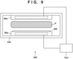
- Fig. 9 is a schematic view showing the arrangement of a plasma processing apparatus 300 as an example of a semiconductor manufacturing apparatus.
- the plasma processing apparatus 300 includes, for example, a CVD apparatus, an etching apparatus, or a sputtering apparatus.
- the plasma processing apparatus 300 includes a chamber 330, and an electrode structure serving as one or a plurality of cooling targets 80a and 80b arranged in the chamber 330.
- a substrate 302 is supported by the cooling target 80a.
- a gas for generating plasma is supplied into the chamber 330.
- the plasma processing apparatus 300 is constituted as a CVD apparatus, a deposition gas is supplied into the chamber 330.
- an etching gas is supplied into the chamber 330.
- the plasma processing apparatus 300 is constituted as a sputtering apparatus, a gas for generating plasma is supplied into the chamber 330, and a target is attached to the electrode structure serving as the cooling target 80b.
- the cooling device CA1 is configured to cool the cooling targets 80a and 80b.
- a semiconductor manufacturing method as one aspect of the present invention includes a step of processing a substrate by a semiconductor manufacturing apparatus represented by the above-described exposure apparatus 100, imprint apparatus 200, and plasma processing apparatus 300, and a step of treating the substrate processed in the step.
- the step of processing the substrate by the semiconductor manufacturing apparatus includes, for example, a step of forming a pattern on the substrate, a step of forming a film on the substrate, or a step of etching the substrate or the film formed on it.
- the step of treating the substrate includes, for example, a step of dividing (dicing) the substrate or a step of sealing the substrate.
- the semiconductor manufacturing method according to this embodiment is advantageous in at least one of the performance, quality, productivity, and production cost of the semiconductor, as compared to conventional methods.
Landscapes
- Engineering & Computer Science (AREA)
- Physics & Mathematics (AREA)
- Mechanical Engineering (AREA)
- Thermal Sciences (AREA)
- General Engineering & Computer Science (AREA)
- General Physics & Mathematics (AREA)
- Life Sciences & Earth Sciences (AREA)
- Sustainable Development (AREA)
- Cooling Or The Like Of Semiconductors Or Solid State Devices (AREA)
- Exposure And Positioning Against Photoresist Photosensitive Materials (AREA)
- Cooling Or The Like Of Electrical Apparatus (AREA)
Applications Claiming Priority (2)
| Application Number | Priority Date | Filing Date | Title |
|---|---|---|---|
| JP2022095225A JP2023181860A (ja) | 2022-06-13 | 2022-06-13 | 冷却装置、半導体製造装置及び半導体製造方法 |
| PCT/JP2023/013209 WO2023243184A1 (fr) | 2022-06-13 | 2023-03-30 | Dispositif de refroidissement, dispositif de fabrication de semi-conducteurs et procédé de fabrication de semi-conducteurs |
Publications (2)
| Publication Number | Publication Date |
|---|---|
| EP4484875A1 true EP4484875A1 (fr) | 2025-01-01 |
| EP4484875A4 EP4484875A4 (fr) | 2026-04-29 |
Family
ID=89192600
Family Applications (1)
| Application Number | Title | Priority Date | Filing Date |
|---|---|---|---|
| EP23823488.4A Pending EP4484875A4 (fr) | 2022-06-13 | 2023-03-30 | Dispositif de refroidissement, dispositif de fabrication de semi-conducteurs et procédé de fabrication de semi-conducteurs |
Country Status (7)
| Country | Link |
|---|---|
| US (1) | US20250012494A1 (fr) |
| EP (1) | EP4484875A4 (fr) |
| JP (1) | JP2023181860A (fr) |
| KR (1) | KR20240146031A (fr) |
| CN (1) | CN119343573A (fr) |
| TW (1) | TWI894548B (fr) |
| WO (1) | WO2023243184A1 (fr) |
Families Citing this family (2)
| Publication number | Priority date | Publication date | Assignee | Title |
|---|---|---|---|---|
| US20240035752A1 (en) * | 2023-08-16 | 2024-02-01 | Kenneth Wealand | Refrigerant Cycling Air Cooling Assembly |
| KR102830022B1 (ko) * | 2024-12-23 | 2025-07-03 | 한화시스템 주식회사 | 상변화 냉각시스템 및 상변화 냉각방법 |
Family Cites Families (10)
| Publication number | Priority date | Publication date | Assignee | Title |
|---|---|---|---|---|
| JPH0660306B2 (ja) * | 1989-06-16 | 1994-08-10 | 三洋電機株式会社 | 冷媒組成物 |
| JP2004232951A (ja) * | 2003-01-30 | 2004-08-19 | Mitsubishi Electric Corp | 冷媒封入方法 |
| JP2007163086A (ja) * | 2005-12-16 | 2007-06-28 | Showa Denko Kk | 冷凍サイクル |
| EP2515170B1 (fr) | 2011-04-20 | 2020-02-19 | ASML Netherlands BV | Système de conditionnement thermique pour le conditionnement thermique d'une pièce d'un appareil lithographique et procédé de conditionnement thermique |
| TW201412966A (zh) * | 2012-08-30 | 2014-04-01 | Du Pont | 為二氟氯甲烷設計之設備的再充填方法 |
| DK3299433T3 (da) * | 2015-05-18 | 2021-01-04 | Nihon Freezer Co Ltd | Ikke-azeotropisk kølemiddel til ultra-lav temperatur |
| JP7026490B2 (ja) * | 2017-11-21 | 2022-02-28 | レール・リキード-ソシエテ・アノニム・プール・レテュード・エ・レクスプロワタシオン・デ・プロセデ・ジョルジュ・クロード | Bog再凝縮装置およびそれを備えるlng貯蔵システム。 |
| US10982887B2 (en) * | 2018-11-20 | 2021-04-20 | Rheem Manufacturing Company | Expansion valve with selectable operation modes |
| JP7565716B2 (ja) * | 2020-06-26 | 2024-10-11 | キヤノン株式会社 | 冷却装置、半導体製造装置および半導体製造方法 |
| JP7692556B2 (ja) | 2020-12-16 | 2025-06-16 | 因幡電機産業株式会社 | 熱膨張性耐火シート、及び、熱膨張性耐火シートの製造方法 |
-
2022
- 2022-06-13 JP JP2022095225A patent/JP2023181860A/ja active Pending
-
2023
- 2023-03-30 KR KR1020247029457A patent/KR20240146031A/ko active Pending
- 2023-03-30 EP EP23823488.4A patent/EP4484875A4/fr active Pending
- 2023-03-30 WO PCT/JP2023/013209 patent/WO2023243184A1/fr not_active Ceased
- 2023-03-30 CN CN202380046064.2A patent/CN119343573A/zh active Pending
- 2023-04-12 TW TW112113602A patent/TWI894548B/zh active
-
2024
- 2024-09-24 US US18/894,357 patent/US20250012494A1/en active Pending
Also Published As
| Publication number | Publication date |
|---|---|
| TWI894548B (zh) | 2025-08-21 |
| JP2023181860A (ja) | 2023-12-25 |
| EP4484875A4 (fr) | 2026-04-29 |
| WO2023243184A1 (fr) | 2023-12-21 |
| US20250012494A1 (en) | 2025-01-09 |
| CN119343573A (zh) | 2025-01-21 |
| TW202349599A (zh) | 2023-12-16 |
| KR20240146031A (ko) | 2024-10-07 |
Similar Documents
| Publication | Publication Date | Title |
|---|---|---|
| US12146696B2 (en) | Cooling device, semiconductor manufacturing apparatus, and semiconductor manufacturing method | |
| US20250012494A1 (en) | Cooling device, semiconductor manufacturing apparatus and semiconductor manufacturing method | |
| JP5210706B2 (ja) | プラズマ処理装置及びプラズマ処理方法 | |
| CN111527452B (zh) | 冷却设备、半导体制造装置和半导体制造方法 | |
| JP5947023B2 (ja) | 温度制御装置、プラズマ処理装置、処理装置及び温度制御方法 | |
| EP1610077B1 (fr) | Procédé pour refroidissement | |
| US11187632B2 (en) | Test chamber and method | |
| US10128141B2 (en) | Plasma processing apparatus and plasma processing method | |
| CN104246407A (zh) | 适于调节卫星的热源的温度的冷却装置和用于生产相关联的冷却装置和卫星的方法 | |
| JP2008034409A (ja) | プラズマ処理装置 | |
| JP3941488B2 (ja) | 冷却装置 | |
| US20260062796A1 (en) | Apparatus for cooling a sputtering target | |
| JP2003222427A (ja) | 温調システム |
Legal Events
| Date | Code | Title | Description |
|---|---|---|---|
| STAA | Information on the status of an ep patent application or granted ep patent |
Free format text: STATUS: THE INTERNATIONAL PUBLICATION HAS BEEN MADE |
|
| PUAI | Public reference made under article 153(3) epc to a published international application that has entered the european phase |
Free format text: ORIGINAL CODE: 0009012 |
|
| STAA | Information on the status of an ep patent application or granted ep patent |
Free format text: STATUS: REQUEST FOR EXAMINATION WAS MADE |
|
| 17P | Request for examination filed |
Effective date: 20240923 |
|
| AK | Designated contracting states |
Kind code of ref document: A1 Designated state(s): AL AT BE BG CH CY CZ DE DK EE ES FI FR GB GR HR HU IE IS IT LI LT LU LV MC ME MK MT NL NO PL PT RO RS SE SI SK SM TR |
|
| DAV | Request for validation of the european patent (deleted) | ||
| DAX | Request for extension of the european patent (deleted) |