EP4484857A1 - Heat exchanger and refrigeration device - Google Patents
Heat exchanger and refrigeration device Download PDFInfo
- Publication number
- EP4484857A1 EP4484857A1 EP23796019.0A EP23796019A EP4484857A1 EP 4484857 A1 EP4484857 A1 EP 4484857A1 EP 23796019 A EP23796019 A EP 23796019A EP 4484857 A1 EP4484857 A1 EP 4484857A1
- Authority
- EP
- European Patent Office
- Prior art keywords
- refrigerant
- plate
- heat exchanger
- heat transfer
- heating medium
- Prior art date
- Legal status (The legal status is an assumption and is not a legal conclusion. Google has not performed a legal analysis and makes no representation as to the accuracy of the status listed.)
- Pending
Links
Images





Classifications
-
- F—MECHANICAL ENGINEERING; LIGHTING; HEATING; WEAPONS; BLASTING
- F28—HEAT EXCHANGE IN GENERAL
- F28D—HEAT-EXCHANGE APPARATUS, NOT PROVIDED FOR IN ANOTHER SUBCLASS, IN WHICH THE HEAT-EXCHANGE MEDIA DO NOT COME INTO DIRECT CONTACT
- F28D9/00—Heat-exchange apparatus having stationary plate-like or laminated conduit assemblies for both heat-exchange media, the media being in contact with different sides of a conduit wall
- F28D9/0006—Heat-exchange apparatus having stationary plate-like or laminated conduit assemblies for both heat-exchange media, the media being in contact with different sides of a conduit wall the plate-like or laminated conduits being enclosed within a pressure vessel
-
- F—MECHANICAL ENGINEERING; LIGHTING; HEATING; WEAPONS; BLASTING
- F25—REFRIGERATION OR COOLING; COMBINED HEATING AND REFRIGERATION SYSTEMS; HEAT PUMP SYSTEMS; MANUFACTURE OR STORAGE OF ICE; LIQUEFACTION SOLIDIFICATION OF GASES
- F25B—REFRIGERATION MACHINES, PLANTS OR SYSTEMS; COMBINED HEATING AND REFRIGERATION SYSTEMS; HEAT PUMP SYSTEMS
- F25B39/00—Evaporators; Condensers
- F25B39/02—Evaporators
-
- F—MECHANICAL ENGINEERING; LIGHTING; HEATING; WEAPONS; BLASTING
- F25—REFRIGERATION OR COOLING; COMBINED HEATING AND REFRIGERATION SYSTEMS; HEAT PUMP SYSTEMS; MANUFACTURE OR STORAGE OF ICE; LIQUEFACTION SOLIDIFICATION OF GASES
- F25B—REFRIGERATION MACHINES, PLANTS OR SYSTEMS; COMBINED HEATING AND REFRIGERATION SYSTEMS; HEAT PUMP SYSTEMS
- F25B39/00—Evaporators; Condensers
- F25B39/02—Evaporators
- F25B39/022—Evaporators with plate-like or laminated elements
-
- F—MECHANICAL ENGINEERING; LIGHTING; HEATING; WEAPONS; BLASTING
- F28—HEAT EXCHANGE IN GENERAL
- F28D—HEAT-EXCHANGE APPARATUS, NOT PROVIDED FOR IN ANOTHER SUBCLASS, IN WHICH THE HEAT-EXCHANGE MEDIA DO NOT COME INTO DIRECT CONTACT
- F28D1/00—Heat-exchange apparatus having stationary conduit assemblies for one heat-exchange medium only, the media being in contact with different sides of the conduit wall, in which the other heat-exchange medium is a large body of fluid, e.g. domestic or motor car radiators
- F28D1/06—Heat-exchange apparatus having stationary conduit assemblies for one heat-exchange medium only, the media being in contact with different sides of the conduit wall, in which the other heat-exchange medium is a large body of fluid, e.g. domestic or motor car radiators with the heat-exchange conduits forming part of, or being attached to, the tank containing the body of fluid
-
- F—MECHANICAL ENGINEERING; LIGHTING; HEATING; WEAPONS; BLASTING
- F28—HEAT EXCHANGE IN GENERAL
- F28D—HEAT-EXCHANGE APPARATUS, NOT PROVIDED FOR IN ANOTHER SUBCLASS, IN WHICH THE HEAT-EXCHANGE MEDIA DO NOT COME INTO DIRECT CONTACT
- F28D9/00—Heat-exchange apparatus having stationary plate-like or laminated conduit assemblies for both heat-exchange media, the media being in contact with different sides of a conduit wall
-
- F—MECHANICAL ENGINEERING; LIGHTING; HEATING; WEAPONS; BLASTING
- F28—HEAT EXCHANGE IN GENERAL
- F28D—HEAT-EXCHANGE APPARATUS, NOT PROVIDED FOR IN ANOTHER SUBCLASS, IN WHICH THE HEAT-EXCHANGE MEDIA DO NOT COME INTO DIRECT CONTACT
- F28D9/00—Heat-exchange apparatus having stationary plate-like or laminated conduit assemblies for both heat-exchange media, the media being in contact with different sides of a conduit wall
- F28D9/0031—Heat-exchange apparatus having stationary plate-like or laminated conduit assemblies for both heat-exchange media, the media being in contact with different sides of a conduit wall the conduits for one heat-exchange medium being formed by paired plates touching each other
- F28D9/0043—Heat-exchange apparatus having stationary plate-like or laminated conduit assemblies for both heat-exchange media, the media being in contact with different sides of a conduit wall the conduits for one heat-exchange medium being formed by paired plates touching each other the plates having openings therein for circulation of at least one heat-exchange medium from one conduit to another
-
- F—MECHANICAL ENGINEERING; LIGHTING; HEATING; WEAPONS; BLASTING
- F28—HEAT EXCHANGE IN GENERAL
- F28D—HEAT-EXCHANGE APPARATUS, NOT PROVIDED FOR IN ANOTHER SUBCLASS, IN WHICH THE HEAT-EXCHANGE MEDIA DO NOT COME INTO DIRECT CONTACT
- F28D9/00—Heat-exchange apparatus having stationary plate-like or laminated conduit assemblies for both heat-exchange media, the media being in contact with different sides of a conduit wall
- F28D9/0031—Heat-exchange apparatus having stationary plate-like or laminated conduit assemblies for both heat-exchange media, the media being in contact with different sides of a conduit wall the conduits for one heat-exchange medium being formed by paired plates touching each other
- F28D9/0043—Heat-exchange apparatus having stationary plate-like or laminated conduit assemblies for both heat-exchange media, the media being in contact with different sides of a conduit wall the conduits for one heat-exchange medium being formed by paired plates touching each other the plates having openings therein for circulation of at least one heat-exchange medium from one conduit to another
- F28D9/005—Heat-exchange apparatus having stationary plate-like or laminated conduit assemblies for both heat-exchange media, the media being in contact with different sides of a conduit wall the conduits for one heat-exchange medium being formed by paired plates touching each other the plates having openings therein for circulation of at least one heat-exchange medium from one conduit to another the plates having openings therein for both heat-exchange media
-
- F—MECHANICAL ENGINEERING; LIGHTING; HEATING; WEAPONS; BLASTING
- F28—HEAT EXCHANGE IN GENERAL
- F28D—HEAT-EXCHANGE APPARATUS, NOT PROVIDED FOR IN ANOTHER SUBCLASS, IN WHICH THE HEAT-EXCHANGE MEDIA DO NOT COME INTO DIRECT CONTACT
- F28D9/00—Heat-exchange apparatus having stationary plate-like or laminated conduit assemblies for both heat-exchange media, the media being in contact with different sides of a conduit wall
- F28D9/0062—Heat-exchange apparatus having stationary plate-like or laminated conduit assemblies for both heat-exchange media, the media being in contact with different sides of a conduit wall the conduits for one heat-exchange medium being formed by spaced plates with inserted elements
- F28D9/0075—Heat-exchange apparatus having stationary plate-like or laminated conduit assemblies for both heat-exchange media, the media being in contact with different sides of a conduit wall the conduits for one heat-exchange medium being formed by spaced plates with inserted elements the plates having openings therein for circulation of the heat-exchange medium from one conduit to another
-
- F—MECHANICAL ENGINEERING; LIGHTING; HEATING; WEAPONS; BLASTING
- F28—HEAT EXCHANGE IN GENERAL
- F28D—HEAT-EXCHANGE APPARATUS, NOT PROVIDED FOR IN ANOTHER SUBCLASS, IN WHICH THE HEAT-EXCHANGE MEDIA DO NOT COME INTO DIRECT CONTACT
- F28D9/00—Heat-exchange apparatus having stationary plate-like or laminated conduit assemblies for both heat-exchange media, the media being in contact with different sides of a conduit wall
- F28D9/02—Heat-exchange apparatus having stationary plate-like or laminated conduit assemblies for both heat-exchange media, the media being in contact with different sides of a conduit wall the heat-exchange media travelling at an angle to one another
-
- F—MECHANICAL ENGINEERING; LIGHTING; HEATING; WEAPONS; BLASTING
- F28—HEAT EXCHANGE IN GENERAL
- F28F—DETAILS OF HEAT-EXCHANGE AND HEAT-TRANSFER APPARATUS, OF GENERAL APPLICATION
- F28F13/00—Arrangements for modifying heat-transfer, e.g. increasing, decreasing
- F28F13/02—Arrangements for modifying heat-transfer, e.g. increasing, decreasing by influencing fluid boundary
-
- F—MECHANICAL ENGINEERING; LIGHTING; HEATING; WEAPONS; BLASTING
- F28—HEAT EXCHANGE IN GENERAL
- F28D—HEAT-EXCHANGE APPARATUS, NOT PROVIDED FOR IN ANOTHER SUBCLASS, IN WHICH THE HEAT-EXCHANGE MEDIA DO NOT COME INTO DIRECT CONTACT
- F28D21/00—Heat-exchange apparatus not covered by any of the groups F28D1/00 - F28D20/00
- F28D2021/0019—Other heat exchangers for particular applications; Heat exchange systems not otherwise provided for
- F28D2021/0068—Other heat exchangers for particular applications; Heat exchange systems not otherwise provided for for refrigerant cycles
Definitions
- the present disclosure relates to a heat exchanger and a refrigeration apparatus.
- a refrigeration apparatus that performs a refrigeration cycle has been known in the art.
- a refrigeration apparatus disclosed in Patent Document 1 has a refrigerant circuit that includes a compressor, a condenser, an expansion valve, and an evaporator.
- This refrigeration apparatus uses a refrigerant, which is, for example, R-1233zd (1-chloro-3,3,3-trifluoropropene).
- R-1233zd is a so-called low-pressure refrigerant.
- Patent Document 1 Japanese Unexamined Patent Publication No. 2019-45135
- an evaporator exchanges heat between a refrigerant and a predetermined heating medium. If this refrigeration apparatus performs a refrigeration cycle where the evaporation pressure of a refrigerant is lower than the atmospheric pressure, the volume of a gas refrigerant evaporated inside a heat exchanger increases. If the contact area between a liquid refrigerant and a heat transfer member (a heat transfer tube) is reduced due to that volume increase, the evaporator exhibits poorer performance of heat exchange between a refrigerant and a heating medium. For this reason, the heat exchanger requires being oversized in order to exhibit secure performance.
- a first aspect is directed to a heat exchanger that is provided in a refrigeration apparatus (R) configured to be capable of performing a refrigeration cycle where an evaporation pressure of a refrigerant is lower than an atmospheric pressure, and that functions as an evaporator, the heat exchanger comprising: a shell (20) forming an internal space (21); and a plate stack (40) arranged in the internal space (21) and including a plurality of heat transfer plates (50a, 50b).
- the plate stack (40) is provided inside the shell (20) of the heat exchanger.
- the plate stack (40) includes the plurality of heat transfer plates (50a, 50b) integrated together, which has a relatively small volume but has a larger heat transfer area.
- this heat exchanger is used as an evaporator of a refrigeration apparatus performing a refrigeration cycle where the evaporation pressure of a refrigerant is lower than the atmospheric pressure, it can exhibit fully secure performance and can avoid being oversized.
- a second aspect is an embodiment of the first aspect.
- the heat exchanger is provided in the refrigeration apparatus (R) configured to be capable of performing a refrigeration cycle where the evaporation pressure of the refrigerant at 0°C or more is lower than the atmospheric pressure.
- the evaporation pressure of a refrigerant even at 0°C or more is lower than the atmospheric pressure, and thus the heat exchanger is likely to exhibit poorer performance of heat exchange between a refrigerant and a heating medium.
- the heat exchanger which includes the plate stack (40), can exhibit secure performance while avoiding being oversized.
- a third aspect is an embodiment of the second aspect.
- the heat exchanger is provided in the refrigeration apparatus (R) using 1-chloro-3,3,3-trifluoropropene as the refrigerant.
- the heat exchanger used in the refrigeration apparatus (R) using a low global warming potential (GWP) can exhibit secure performance while avoiding being oversized.
- a fourth aspect is an embodiment of any one of the first to third aspects.
- a pitch P between the plurality of heat transfer plates (50a, 50b) is more than 1.2 mm.
- the volume of bubbles consisting of the evaporated gas refrigerant is likely to increase.
- the pitch P between the heat transfer plates (50a, 50b) adjacent to each other is too small, the bubbles become spreadable along the heat transfer plates (50a, 50b) in the refrigerant channel formed between the heat transfer plates (50a, 50b) adjacent to each other.
- the contact area between the heat transfer plates (50a, 50b) and the gas refrigerant increases, whereas the contact area between the heat transfer plates (50a, 50b) and the liquid refrigerant decreases. Accordingly, the plate stack (40) exhibits poorer performance of heat exchange between a refrigerant and a predetermined heating medium.
- the pitch P between the plurality of heat transfer plates (50a, 50b) adjacent to each other is 1.2 mm or more. Accordingly, in the refrigerant channel between the heat transfer plates (50a, 50b) adjacent to each other, the gas refrigerant becomes less spreadable along the heat transfer plates (50a, 50b). As a result, reduction in the contact area between the heat transfer plates (50a, 50b) and the liquid refrigerant due to production of bubbles can be reduced, and poorer performance of the heat exchanger can be reduced.
- a fifth aspect is an embodiment of the fourth aspect.
- the pitch P is 1.5 mm or more.
- the pitch P is 1.5 mm or more. Accordingly, reduction in the contact area between the heat transfer plates (50a, 50b) and the liquid refrigerant can be further reduced, and poorer performance of the heat exchanger can be further reduced.
- a sixth aspect is an embodiment of the fifth aspect.
- the pitch P is 2.1 mm or less.
- the pitch P is too large, the refrigerant flows at a lower speed in the refrigerant channel between the heat transfer plates (50a, 50b) adjacent to each other, and the heat exchanger exhibits poorer performance.
- the pitch P between the plurality of heat transfer plates (50a, 50b) is 2.1 mm or less. Accordingly, lowering of the flow speed of the refrigerant can be reduced, poorer performance of the heat exchanger can be reduced.
- a seventh aspect is an embodiment of any one of the first to sixth aspects.
- a surface of the heat transfer plate (50a, 50b) has a rough portion (80).
- the surface of the heat transfer plate (50a, 50b) of the seventh aspect has the rough portion (80) for making the surface rough.
- the rough portion (80) improves the wettability of a liquid refrigerant on the surface of the heat transfer plate (50a, 50b), and thus the performance of the heat exchanger can be improved.
- An eighth aspect is directed to a refrigeration apparatus including: the heat exchanger (10) of any one of the first to seventh aspects.
- the refrigeration apparatus is configured to be capable of performing the refrigeration cycle where the evaporation pressure of the refrigerant is lower than the atmospheric pressure.
- the refrigeration apparatus which is capable of performing the refrigeration cycle where the evaporation pressure of the refrigerant is lower than the atmospheric pressure and which keeps the heat exchanger (10) from being oversized can be provided.
- a heat exchanger (10) of the present disclosure is a shell-and-plate heat exchanger.
- the heat exchanger (10) is provided in a refrigeration apparatus (R).
- the refrigeration apparatus (R) of this example is a chiller unit that produces cold water.
- the refrigeration apparatus (R) includes a refrigerant circuit (1) filled with a refrigerant.
- the refrigerant circuit (1) has a compressor (2), a radiator (3), a decompression mechanism (4), and an evaporator (5).
- the heat exchanger (10) of the present disclosure constitutes the evaporator (5).
- the refrigerant circuit (1) performs a vapor compression refrigeration cycle.
- the compressor (2) is a screw compressor, but may be any other type of compressor, such as a turbo compressor, a scroll compressor, an oscillating piston compressor, or a rotary compressor.
- the refrigerant compressed by the compressor (2) dissipates heat in the radiator (3).
- the refrigerant which has dissipated heat is decompressed by the decompression mechanism (4) and evaporates in the evaporator (5).
- the evaporated refrigerant is sucked into the compressor (2).
- the refrigerant circuit (1) may include a switching mechanism such as a four-way switching valve that switches channels of a refrigerant.
- the heat exchanger (10) functions as an evaporator or a condenser.
- the heat exchanger (10) includes a shell (20) and a plate stack (40).
- the plate stack (40) is housed in an internal space (21) of the shell (20).
- a liquid refrigerant flows into the internal space (21) of the shell (20).
- the liquid refrigerant exchanges heat with a heating medium flowing in the plate stack (40).
- the heat exchanger (10) evaporates a refrigerant having flowed into the internal space (21) of the shell (20), thereby functioning as an evaporator.
- the heating medium include water and brine.
- the shell (20) is comprised of a closed container having a horizontally long, cylindrical shape.
- the shell (20) has a barrel (20a), a first sidewall (20b), and a second sidewall (20c).
- the barrel (20a) is formed in a cylindrical shape.
- the first sidewall (20b) is formed in a circular shape and blocks a left end of the barrel (20a).
- the second sidewall (20c) is formed in a circular shape and blocks a right end of the barrel (20a).
- the shell (20) forms the internal space (21) defined by the barrel (20a), the first sidewall (20b), and the second sidewall (20c).
- the internal space (21) stores a liquid refrigerant.
- the barrel (20a) has a refrigerant inlet (32) and a refrigerant outlet (33).
- the refrigerant inlet (32) is formed at the bottom of the barrel (20a).
- a refrigerant is introduced into the internal space (21) through the refrigerant inlet (32).
- the refrigerant outlet (33) is formed at the top of the barrel (20a).
- the refrigerant evaporated in the internal space (21) is emitted out of the shell (20) through the refrigerant outlet (33).
- the refrigerant inlet (32) and the refrigerant outlet (33) are connected to the refrigerant circuit via pipes.
- the first sidewall (20b) is provided with a heating medium inlet (23) and a heating medium outlet (24).
- the heating medium inlet (23) and the heating medium outlet (24) are tubular members.
- the heating medium inlet (23) is disposed above the heating medium outlet (24).
- a heating medium flows from the upper side toward the lower side of the plate stack (40).
- the heating medium inlet (23) may be disposed below the heating medium outlet (24). In this case, the heating medium flows from the lower side toward the upper side of the plate stack (40).
- the heating medium inlet (23) penetrates substantially the center of the first sidewall (20b).
- the heating medium inlet (23) is connected to a heating medium introduction path (43) of the plate stack (40) to supply the heating medium to the plate stack (40).
- the heating medium outlet (24) penetrates the first sidewall (20b) at a substantially intermediate position between the heating medium inlet (23) and a lower end of the first sidewall (20b).
- the heating medium outlet (24) is connected to a heating medium emission path (44) of the plate stack (40) to emit the heating medium out of the plate stack.
- the plate stack (40) includes a plurality of heat transfer plates (50a, 50b) stacked in the lateral direction and joined together.
- the plate stack (40) is housed in the internal space (21) of the shell (20) with the stacking direction of the heat transfer plates (50a, 50b) extending in the lateral direction.
- the heat transfer plates (50a, 50b) constituting the plate stack (40) are substantially semicircular plate-shaped members.
- the width of each heat transfer plate (50a, 50b) increases toward the upper end thereof.
- the plate stack (40) is arranged near the bottom of the internal space (21) of the shell (20) with arc-shaped edges of the heat transfer plates (50a, 50b) facing downward.
- supports in the shape of protrusions for supporting the plate stack (40) protrude from the inner surface of the shell (20).
- the plate stack (40) housed in the internal space (21) of the shell (20) is spaced apart from the inner surface of the shell (20), and forms a gap (25) between the edges facing downward of the heat transfer plates (50a, 50b) of the plate stack (40) and the inner surface of the shell (20).
- An upper space (21a) is formed above the plate stack (40) in the internal space (21).
- the plate stack (40) includes a first plate (50a) and a second plate (50b) as the heat transfer plates (50a, 50b), each having different shapes.
- the plate stack (40) includes a plurality of first plates (50a) and a plurality of second plates (50b).
- the first plate (50a) and the second plate (50b) are stacked alternately.
- a surface on the left in FIG. 4 will be referred to as a front surface
- a surface on the right in FIG. 4 will be referred to as a back surface.
- the first plate (50a) has a lower protrusion (51a) and an upper protrusion (53a).
- Each of the lower protrusion (51a) and the upper protrusion (53a) is a circular portion bulging toward the front side of the first plate (50a).
- Each of the lower protrusion (51a) and the upper protrusion (53a) is formed in a widthwise center portion of the first plate (50a).
- the lower protrusion (51a) is formed in a lower portion of the first plate (50a).
- the upper protrusion (53a) is formed in an upper portion of the first plate (50a).
- a first lower hole (52a) is formed in a center portion of the lower protrusion (51a).
- a first upper hole (54a) is formed in a center portion of the upper protrusion (53a).
- Each of the first lower hole (52a) and the first upper hole (54a) is a circular hole penetrating the first plate (50a) in a thickness direction.
- the second plate (50b) has a lower recess (51b) and an upper recess (53b).
- Each of the lower recess (51b) and the upper recess (53b) is a circular portion bulging toward the back side of the second plate (50b).
- Each of the lower recess (51b) and the upper recess (53b) is formed in a widthwise center portion of the second plate (50b).
- the lower recess (51b) is formed in a lower portion of the second plate (50b).
- the upper recess (53b) is formed in an upper portion of the second plate (50b).
- a second lower hole (52b) is formed in a center portion of the lower recess (51b).
- a second upper hole (54b) is formed in a center portion of the upper recess (53b).
- Each of the second lower hole (52b) and the second upper hole (54b) is a circular hole penetrating the second plate (50b) in a thickness direction.
- the second plate (50b) has the lower recess (51b) formed at a position corresponding to the lower protrusion (51a) of the first plate (50a), and the upper recess (53b) formed at a position corresponding to the upper protrusion (53a) of the first plate (50a).
- the second plate (50b) has the second lower hole (52b) formed at a position corresponding to the first lower hole (52a) of the first plate (50a), and the second upper hole (54b) formed at a position corresponding to the first upper hole (54a) of the first plate (50a).
- the first lower hole (52a) and the second lower hole (52b) have a substantially equal diameter.
- the first upper hole (54a) and the second upper hole (54b) have a substantially equal diameter.
- each first plate (50a) and an adjacent one of the second plates (50b) on the back side of the first plate (50a) are welded together at their peripheral portions along the whole perimeter.
- the first lower hole (52a) of each first plate (50a) overlaps the second lower hole (52b) of an adjacent one of the second plates (50b) on the front side of the first plate (50a), and the rims of the overlapping first lower hole (52a) and second lower hole (52b) are welded together along the entire perimeter.
- the first upper hole (54a) of each first plate (50a) overlaps the second upper hole (54b) of an adjacent one of the second plates (50b) on the front side of the first plate (50a), and the rims of the overlapping first upper hole (54a) and second upper hole (54b) are welded together along the entire perimeter.
- the lower protrusions (51a) and first lower holes (52a) of the first plates (50a) and the lower recesses (51b) and second lower holes (52b) of the second plates (50b) form the heating medium emission path (44).
- the upper protrusions (53a) and first upper holes (54a) of the first plates (50a) and the upper recesses (53b) and second upper holes (54b) of the second plates (50b) form the heating medium introduction path (43).
- the heating medium introduction path (43) and the heating medium emission path (44) are passages extending in the stacking direction of the heat transfer plates (50a, 50b) in the plate stack (40).
- the heating medium introduction path (43) and the heating medium emission path (44) are passages blocked from the internal space (21) of the shell (20).
- the heating medium introduction path (43) communicates with all the heating medium channels (42), and is connected to the heating medium inlet (23).
- the heating medium emission path (44) communicates with all the heating medium channels (42), and is connected to the heating medium outlet (24).
- the plate stack (40) includes refrigerant channels (41) and heating medium channels (42), each of the heating medium channels (42) being adjacent to an associated one of the refrigerant channels (41) with the heat transfer plate (50a, 50b) interposed therebetween.
- the refrigerant channel (41) and the corresponding heating medium channel (42) are separated from each other by the heat transfer plate (50a, 50b).
- the first plate (50a) and the second plate (50b) have a first corrugated pattern (62a) a second corrugated pattern (62b), respectively, each of which includes repetition of long, narrow ridges and grooves. As illustrated in FIGS.
- the ridges and grooves of the first corrugated pattern (62a) extend at a first angle ⁇ 1 to a horizontal direction X
- the ridges and grooves of the second corrugated pattern (62b) extend at a second angle ⁇ 2 to the horizontal direction X.
- the first angle ⁇ 1 and the second angle ⁇ 2 have supplementary angles. For example, when the first angle ⁇ 1 is 45 degrees, the second angle ⁇ 2 is 135 degrees.
- the first angle ⁇ 1 ranges from 15 degrees to 75 degrees.
- the second angle ⁇ 2 ranges from 165 degrees to 105 degrees.
- the refrigerant channel (41) is a channel sandwiched between the front surface of the first plate (50a) and the back surface of the second plate (50b).
- the refrigerant channel (41) is a channel that communicating with the internal space (21) of the shell (20) and allowing the refrigerant to flow therethrough.
- the heating medium channel (42) is a channel sandwiched between the back surface of the first plate (50a) and the front surface of the second plate (50b). The heating medium channel (42) is blocked from the internal space of the shell (20).
- the heating medium channel (42) is provided with a guide (70).
- the guide (70) includes a first linear flat portion (65a) and a second linear flat portion (65b).
- the first linear flat portion is linearly formed on the back surface of the first plate (50a).
- the first linear flat portion (65a) bulges toward the back side of the first plate (50a), and has a flat bulging top.
- the first linear flat portion (65a) extends linearly in the width direction of the heat transfer plate (50a, 50b).
- the second linear flat portion (65b) is linearly formed on the front surface of the second plate (50b).
- the second linear flat portion (65b) bulges toward the front side of the second plate (50b), and has a flat bulging top.
- the second linear flat portion (65b) extends linearly in the width direction of the heat transfer plate (50a, 50b).
- the second linear flat portion (65b) is formed at a position corresponding to the first linear flat portion (65a) with the first plate (50a) and the second plate (50b) being stacked.
- the guide (70) is arranged symmetrically with respect to a center line Y of the heat transfer plate (50a, 50b).
- FIGS. 7 and 8 show how the heating medium and the refrigerant flow in the heat exchanger (10).
- Arrows shown in FIG. 7 indicate the flow of the heating medium.
- FIG. 8 shows that the liquid refrigerant is stored in the shell. Solid arrows indicate the flow of the heating medium, and broken line arrows indicate the flow of the refrigerant.
- the heating medium flows from the heating medium inlet (23) into the heating medium introduction path (43).
- the heating medium flowing through the heating medium introduction path (43) flows through the heating medium channels (42).
- the heating medium flows downward while flowing toward both lateral ends of the heat transfer plate (50a, 50b).
- the heating medium that has flowed into the heating medium channels (42) is guided toward side portions of the heat transfer plate (50a, 50b) by the guide (70).
- the guide (70) prevents the heating medium from flowing downward in the heating medium channels (42), and allows the heating medium to flow toward the side portions of the heat transfer plate (50a, 50b).
- the heating medium that has moved to the side portions of the heat transfer plate (50a, 50b) by the guide (70) flows to a lower portion of the heat transfer plate (50a, 50b).
- the heating medium enters the heating medium emission path (44).
- the refrigerant that has passed through an expansion valve in the refrigerant circuit flows toward the heat exchanger (10).
- This liquid refrigerant flows into the internal space (21) of the shell (20) through the refrigerant inlet (32).
- the liquid refrigerant stored in the internal space (21) reaches close to the upper end of the plate stack (40).
- the plate stack (40) is immersed in the liquid refrigerant.
- the refrigerant stored in the internal space (21) has a relatively low pressure.
- the low-pressure refrigerant exchanges heat with the heating medium flowing through the heating medium channels (42).
- the refrigerant channel (41) and the heating medium channel (42) are adjacent to each other with the heat transfer plate (50a, 50b) interposed therebetween.
- the liquid refrigerant absorbs heat from the heating medium flowing through the heating medium channel (42) and evaporates.
- the evaporated refrigerant moves from the refrigerant channel (41) to the upper space (21a) which is an upper portion of the internal space (21).
- the refrigerant in the upper space (21a) flows into the refrigerant circuit through the refrigerant outlet (33).
- the refrigeration apparatus (R) of the present disclosure uses a refrigerant, in particular, a so-called low-pressure refrigerant.
- the refrigeration apparatus (R) uses a refrigerant of which the evaporation pressure at 0°C or more is lower than the atmospheric pressure.
- this refrigerant is, for example, R-1233zd (1-chloro-3,3,3-trifluoropropene).
- the refrigerant R-1233zd has a low global warming potential (GWP), and thus enables the refrigeration apparatus (R) to be environmentally friendly.
- the refrigeration apparatus (R) may use refrigerants, such as R1233zd(E) (trans-1-chloro-3,3,3-trifluoropropene), R1224yd(z) (1-chloro-2,3,3,3-tetrafluoropropene), and R-1336mzz(Z) (1,1, 1,4,4,4-hexafluoro-2-butene).
- refrigerants such as R1233zd(E) (trans-1-chloro-3,3,3-trifluoropropene), R1224yd(z) (1-chloro-2,3,3,3-tetrafluoropropene), and R-1336mzz(Z) (1,1, 1,4,4,4-hexafluoro-2-butene).
- the refrigeration apparatus (R) is capable of performing a refrigeration cycle where the evaporation pressure of the refrigerant is lower than the atmospheric pressure in the heat exchanger (10) functioning as an evaporator.
- the refrigeration apparatus (R) performs the refrigeration cycle where the evaporation pressure of the refrigerant is lower than the atmospheric pressure during rated operation. More precisely, the refrigeration apparatus (R) performs the refrigeration cycle where the evaporation pressure of a refrigerant at 0°C or more is lower than the atmospheric pressure during rated operation.
- the dimension and so on of the plurality of heat transfer plates (50a, 50b) are set as follows.
- the left side in FIG. 9 will be referred to as the front side of the plate stack (40)
- the right side in FIG. 9 will be referred to as the rear side of the plate stack (40).
- the stacking direction of the heat transfer plates (50a, 50b) corresponds to the front-to-rear direction.
- the plurality of heat transfer plates (50a, 50b) are arranged in the front-to-rear direction.
- the first plate (50a) and the second plate (50b) are alternately and repeatedly arranged.
- the position of the foremost portion of the back surface of the second plate (50b) is referred to as "a”
- the position of the rearmost portion of the back surface of the second plate (50b) is referred to as "b.”
- the position of the foremost portion of the front surface of the first plate (50a) is equivalent to the position b.
- the position of the rearmost portion of the front surface of the first plate (50a) is referred to as "c.”
- the distance from the position a to the position b on the second plate (50b) is referred to as "P1," and the distance from the position b to the position c on the first plate (50a) is referred to as "P2.”
- the distance P1 corresponds to the length of the first channel (41a) of the refrigerant channel (41) formed on the back side of the second plate (50b) in the front-to-rear direction (the channel height).
- the distance P2 corresponds to the length of the second channel (41b) of the refrigerant channel (41) formed on the front side of the first plate (50a) in the front-to-rear direction (the channel height).
- the distances P1 and P2 are equal to each other.
- the pitch P between the heat transfer plates (50a, 50b) adjacent to each other is the pitch between the center line m1 and the center line m2.
- the pitch P is the interval between the center line m1 of the channel height (P1) of the first channel (41a) on the back side of the second plate (50b) and the center line m2 of the channel height (P2) of the second channel (41b) on the front side of the first plate (50a).
- the center line m1 is a line segment that passes through the intermediate position of the first channel (41a) in the front-to-rear direction and that is orthogonal to the front-to-rear direction.
- the center line m2 is a line segment that passes through the intermediate position of the second channel (41b) in the front-to-rear direction and that is orthogonal to the front-to-rear direction.
- the pitch P is equal to P1 and P2.
- the pitch P is set so as to improve the heat exchange performance of the plate stack (40).
- the pitch P is preferably more than 1.2 mm, and more preferably 1.5 mm or more.
- the pitch P is preferably 2.1 mm or less, and more preferably 1.8 mm or less.
- P1 and P2 are preferably more than 1.2 mm, and more preferably 1.5 mm or more.
- P1 and the P2 are preferably 2.1 mm or less, and more preferably 1.8 mm or less.
- FIG. 10 shows the results of evaluation of the relationship between the pitches P of the plurality of heat transfer plates (50a, 50b) and the performance of heat exchange.
- the various pitches P of the heat transfer plates (50a, 50b) 1.2 mm, 1.5 mm, 1.8 mm, and 2.1 mm
- the heat flux and heat transfer coefficient in the heat transfer plates (50a, 50b) obtained when R-1233zd flowed through the refrigerant channels (41) were observed.
- the heat flux is represented by the horizontal axis
- the heat transfer coefficient is represented by the vertical axis.
- the heat transfer coefficient tends to be lower than those of the other pitches.
- the heat transfer coefficient is lower than those of the other pitches.
- the refrigerant is gasified, thereby producing bubbles.
- a refrigerant in particular, a so-called low-pressure refrigerant such as R-1233zd
- the volume of the bubbles is likely to increase.
- the pitch P is too small, the bubbles become spreadable along the heat transfer plates (50a, 50b).
- the contact area between the liquid refrigerant and the heat transfer plates (50a, 50b) are reduced, and the heat transfer coefficient is also likely to be reduced.
- the pitch is greater than 1.2 mm, the bubbles become less spreadable along the heat transfer plates (50a, 50b).
- the reduction in the heat transfer coefficient due to production of the bubbles can be reduced.
- the pitch P is 1.5 mm or more, the heat transfer coefficient is high in a wide range of the heat flux. In contrast, if the pitch P is 2.1 mm, the heat transfer coefficient is lower than if the pitch P is 1.8 mm. This seems because the pitch P that was too large caused the refrigerant to flow through the refrigerant channels (41) at a lower speed.
- the pitch P is preferably more than 1.2 mm, more preferably 1.5 mm or more, and still more preferably 1.5 mm or more and 2.1 mm or less.
- the heat exchanger (10) is provided in the refrigeration apparatus (R) configured to be capable of performing a refrigeration cycle where the evaporation pressure of a refrigerant is lower than the atmospheric pressure, and the heat exchanger (10) functions as an evaporator.
- the heat exchanger (10) includes the shell (20) forming the internal space (21) and includes the plate stack (40) arranged in the internal space (21) and including the plurality of heat transfer plates (50a, 50b).
- the heat exchanger (10) serving as an evaporator is likely to exhibit poorer performance of heat exchange because the volume of a gasified refrigerant increases.
- the heat exchanger (10) consists of the plate stack (40) including the plurality of heat transfer plates (50a, 50b) stacked together, and thus the heat exchanger (10) can exhibit secure performance while avoiding being oversized.
- the heat exchanger (10) is provided in the refrigeration apparatus (R) configured to be capable of performing a refrigeration cycle where the evaporation pressure of a refrigerant at 0°C or more is lower than the atmospheric pressure. Specifically, the heat exchanger (10) is provided in the refrigeration apparatus (R) using 1-chloro-3,3,3-trifluoropropene as a refrigerant.
- This refrigeration apparatus (R) using a so-called low-pressure refrigerant can still allow the heat exchanger (10) to exhibit secure performance while avoiding being oversized.
- the pitch P between the plurality of heat transfer plates (50a, 50b) is 1.2 mm or more, poorer performance of the heat exchanger (10) due to production of the bubbles can be reduced. If the pitch P is particularly 1.5 mm or more, the performance of the heat exchanger (10) can be improved as can be clarified from FIG. 10 . Further, if the pitch P is 1.8 mm or more, poorer performance of the heat exchanger (10) due to the refrigerant flowing through the refrigerant channels (41) at a lower speed can be reduced.
- a surface of the heat transfer plate (50a, 50b) has a rough portion (80).
- the rough portion (80) is formed on a portion of the heat transfer plate (50a, 50b) facing the refrigerant channel (41).
- the rough portion (80) is formed by spraying a predetermined medium onto the surface of the heat transfer plate (50a, 50b) through the sandblasting process.
- the roughness of the rough portion (80) of the heat transfer plate (50a, 50b) improves the wettability of a liquid refrigerant on the surface of the heat transfer plate (50a, 50b). Accordingly, the performance of the heat exchanger (10) can be improved.
- the heat exchanger (10) of the embodiment may be a falling-film-type, shell-and-plate heat exchanger.
- the heat exchanger (10) may include a sprayer arranged above the plate stack (40) in the shell (20) to spray the liquid refrigerant onto the plate stack (40).
- the heat exchanger (10) may include a plate stack having a structure that enables spraying of a liquid refrigerant.
- the present disclosure is useful for a heat exchanger and a refrigeration apparatus.
Landscapes
- Engineering & Computer Science (AREA)
- Physics & Mathematics (AREA)
- Mechanical Engineering (AREA)
- Thermal Sciences (AREA)
- General Engineering & Computer Science (AREA)
- Heat-Exchange Devices With Radiators And Conduit Assemblies (AREA)
Abstract
Description
- The present disclosure relates to a heat exchanger and a refrigeration apparatus.
- A refrigeration apparatus that performs a refrigeration cycle has been known in the art. A refrigeration apparatus disclosed in
Patent Document 1 has a refrigerant circuit that includes a compressor, a condenser, an expansion valve, and an evaporator. This refrigeration apparatus uses a refrigerant, which is, for example, R-1233zd (1-chloro-3,3,3-trifluoropropene). R-1233zd is a so-called low-pressure refrigerant. - Patent Document 1:
Japanese Unexamined Patent Publication No. 2019-45135 - In the refrigeration apparatus of
Patent Document 1, an evaporator exchanges heat between a refrigerant and a predetermined heating medium. If this refrigeration apparatus performs a refrigeration cycle where the evaporation pressure of a refrigerant is lower than the atmospheric pressure, the volume of a gas refrigerant evaporated inside a heat exchanger increases. If the contact area between a liquid refrigerant and a heat transfer member (a heat transfer tube) is reduced due to that volume increase, the evaporator exhibits poorer performance of heat exchange between a refrigerant and a heating medium. For this reason, the heat exchanger requires being oversized in order to exhibit secure performance. - It is an object of the present disclosure to provide a heat exchanger that can be used for a refrigeration apparatus performing a refrigeration cycle where the evaporation pressure of a refrigerant is lower than the atmospheric pressure, but that can avoid being oversized.
- A first aspect is directed to a heat exchanger that is provided in a refrigeration apparatus (R) configured to be capable of performing a refrigeration cycle where an evaporation pressure of a refrigerant is lower than an atmospheric pressure, and that functions as an evaporator, the heat exchanger comprising: a shell (20) forming an internal space (21); and a plate stack (40) arranged in the internal space (21) and including a plurality of heat transfer plates (50a, 50b).
- According to the first aspect, the plate stack (40) is provided inside the shell (20) of the heat exchanger. The plate stack (40) includes the plurality of heat transfer plates (50a, 50b) integrated together, which has a relatively small volume but has a larger heat transfer area. Thus, even if this heat exchanger is used as an evaporator of a refrigeration apparatus performing a refrigeration cycle where the evaporation pressure of a refrigerant is lower than the atmospheric pressure, it can exhibit fully secure performance and can avoid being oversized.
- A second aspect is an embodiment of the first aspect. In the second aspect, the heat exchanger is provided in the refrigeration apparatus (R) configured to be capable of performing a refrigeration cycle where the evaporation pressure of the refrigerant at 0°C or more is lower than the atmospheric pressure.
- According to the second aspect, the evaporation pressure of a refrigerant even at 0°C or more is lower than the atmospheric pressure, and thus the heat exchanger is likely to exhibit poorer performance of heat exchange between a refrigerant and a heating medium. However, the heat exchanger, which includes the plate stack (40), can exhibit secure performance while avoiding being oversized.
- A third aspect is an embodiment of the second aspect. In the third aspect, the heat exchanger is provided in the refrigeration apparatus (R) using 1-chloro-3,3,3-trifluoropropene as the refrigerant.
- According to the third aspect, the heat exchanger used in the refrigeration apparatus (R) using a low global warming potential (GWP) can exhibit secure performance while avoiding being oversized.
- A fourth aspect is an embodiment of any one of the first to third aspects. In the fourth aspect, a pitch P between the plurality of heat transfer plates (50a, 50b) is more than 1.2 mm.
- In the evaporator of the refrigeration apparatus (R) performing a refrigeration cycle where the evaporation pressure of a refrigerant is lower than the atmospheric pressure, the volume of bubbles consisting of the evaporated gas refrigerant is likely to increase. Thus, if the pitch P between the heat transfer plates (50a, 50b) adjacent to each other is too small, the bubbles become spreadable along the heat transfer plates (50a, 50b) in the refrigerant channel formed between the heat transfer plates (50a, 50b) adjacent to each other. As a result, the contact area between the heat transfer plates (50a, 50b) and the gas refrigerant increases, whereas the contact area between the heat transfer plates (50a, 50b) and the liquid refrigerant decreases. Accordingly, the plate stack (40) exhibits poorer performance of heat exchange between a refrigerant and a predetermined heating medium.
- In contrast, according to the fourth aspect, in the plate stack (40), the pitch P between the plurality of heat transfer plates (50a, 50b) adjacent to each other is 1.2 mm or more. Accordingly, in the refrigerant channel between the heat transfer plates (50a, 50b) adjacent to each other, the gas refrigerant becomes less spreadable along the heat transfer plates (50a, 50b). As a result, reduction in the contact area between the heat transfer plates (50a, 50b) and the liquid refrigerant due to production of bubbles can be reduced, and poorer performance of the heat exchanger can be reduced.
- A fifth aspect is an embodiment of the fourth aspect. In the fifth aspect, the pitch P is 1.5 mm or more.
- According to the fifth aspect, the pitch P is 1.5 mm or more. Accordingly, reduction in the contact area between the heat transfer plates (50a, 50b) and the liquid refrigerant can be further reduced, and poorer performance of the heat exchanger can be further reduced.
- A sixth aspect is an embodiment of the fifth aspect. In the sixth aspect, the pitch P is 2.1 mm or less.
- If the pitch P is too large, the refrigerant flows at a lower speed in the refrigerant channel between the heat transfer plates (50a, 50b) adjacent to each other, and the heat exchanger exhibits poorer performance.
- In contrast, according to the sixth aspect, the pitch P between the plurality of heat transfer plates (50a, 50b) is 2.1 mm or less. Accordingly, lowering of the flow speed of the refrigerant can be reduced, poorer performance of the heat exchanger can be reduced.
- A seventh aspect is an embodiment of any one of the first to sixth aspects. In the seventh aspect, a surface of the heat transfer plate (50a, 50b) has a rough portion (80).
- The surface of the heat transfer plate (50a, 50b) of the seventh aspect has the rough portion (80) for making the surface rough. The rough portion (80) improves the wettability of a liquid refrigerant on the surface of the heat transfer plate (50a, 50b), and thus the performance of the heat exchanger can be improved.
- An eighth aspect is directed to a refrigeration apparatus including: the heat exchanger (10) of any one of the first to seventh aspects.
The refrigeration apparatus is configured to be capable of performing the refrigeration cycle where the evaporation pressure of the refrigerant is lower than the atmospheric pressure. - According to the eighth aspect, the refrigeration apparatus which is capable of performing the refrigeration cycle where the evaporation pressure of the refrigerant is lower than the atmospheric pressure and which keeps the heat exchanger (10) from being oversized can be provided.
-
-
FIG. 1 is a schematic diagram of a refrigeration apparatus according to an embodiment. -
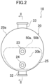
FIG. 2 is a plan view of a heat exchanger. -
FIG. 3 is a cross-sectional view taken along line II-II shown inFIG. 2 . -
FIG. 4 is a partially-enlarged, schematic, longitudinal-cross-sectional view of a plate stack. -
FIG. 5 is a front view of a first plate. -
FIG. 6 is a front view of a second plate. -
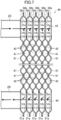
FIG. 7 is a schematic view of the flow of a heating medium in the plate stack. -
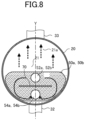
FIG. 8 is a schematic view of the flow of the heating medium on a heat transfer plate. -
FIG. 9 is a partially-enlarged, schematic, longitudinal-cross-sectional view of a plate stack with dimensions. -
FIG. 10 is a graph showing the evaluation of the relationship between the heat flux and the heat transfer coefficient in the heat exchanger including a plurality of heat transfer plates having various pitches. -
FIG. 11 is a partially-enlarged, longitudinal-cross-sectional view of a plate stack of a heat exchanger according to a first variation. - Embodiments will be described below with reference to the drawings. The following embodiments are merely exemplary ones in nature, and are not intended to limit the scope, applications, or use of the invention.
- A heat exchanger (10) of the present disclosure is a shell-and-plate heat exchanger. The heat exchanger (10) is provided in a refrigeration apparatus (R). The refrigeration apparatus (R) of this example is a chiller unit that produces cold water.
- As illustrated in
FIG. 1 , the refrigeration apparatus (R) includes a refrigerant circuit (1) filled with a refrigerant. The refrigerant circuit (1) has a compressor (2), a radiator (3), a decompression mechanism (4), and an evaporator (5). The heat exchanger (10) of the present disclosure constitutes the evaporator (5). The refrigerant circuit (1) performs a vapor compression refrigeration cycle. The compressor (2) is a screw compressor, but may be any other type of compressor, such as a turbo compressor, a scroll compressor, an oscillating piston compressor, or a rotary compressor. - In the refrigeration cycle, the refrigerant compressed by the compressor (2) dissipates heat in the radiator (3). The refrigerant which has dissipated heat is decompressed by the decompression mechanism (4) and evaporates in the evaporator (5). The evaporated refrigerant is sucked into the compressor (2).
- The refrigerant circuit (1) may include a switching mechanism such as a four-way switching valve that switches channels of a refrigerant. In this case, the heat exchanger (10) functions as an evaporator or a condenser.
- As illustrated in
FIGS. 2 and3 , the heat exchanger (10) includes a shell (20) and a plate stack (40). The plate stack (40) is housed in an internal space (21) of the shell (20). A liquid refrigerant flows into the internal space (21) of the shell (20). The liquid refrigerant exchanges heat with a heating medium flowing in the plate stack (40). The heat exchanger (10) evaporates a refrigerant having flowed into the internal space (21) of the shell (20), thereby functioning as an evaporator. Examples of the heating medium include water and brine. - The shell (20) is comprised of a closed container having a horizontally long, cylindrical shape. The shell (20) has a barrel (20a), a first sidewall (20b), and a second sidewall (20c). The barrel (20a) is formed in a cylindrical shape. The first sidewall (20b) is formed in a circular shape and blocks a left end of the barrel (20a). The second sidewall (20c) is formed in a circular shape and blocks a right end of the barrel (20a). The shell (20) forms the internal space (21) defined by the barrel (20a), the first sidewall (20b), and the second sidewall (20c). The internal space (21) stores a liquid refrigerant.
- The barrel (20a) has a refrigerant inlet (32) and a refrigerant outlet (33). The refrigerant inlet (32) is formed at the bottom of the barrel (20a). A refrigerant is introduced into the internal space (21) through the refrigerant inlet (32). The refrigerant outlet (33) is formed at the top of the barrel (20a). The refrigerant evaporated in the internal space (21) is emitted out of the shell (20) through the refrigerant outlet (33). The refrigerant inlet (32) and the refrigerant outlet (33) are connected to the refrigerant circuit via pipes.
- The first sidewall (20b) is provided with a heating medium inlet (23) and a heating medium outlet (24). The heating medium inlet (23) and the heating medium outlet (24) are tubular members. In this example, the heating medium inlet (23) is disposed above the heating medium outlet (24). In other words, a heating medium flows from the upper side toward the lower side of the plate stack (40). The heating medium inlet (23) may be disposed below the heating medium outlet (24). In this case, the heating medium flows from the lower side toward the upper side of the plate stack (40).
- The heating medium inlet (23) penetrates substantially the center of the first sidewall (20b). The heating medium inlet (23) is connected to a heating medium introduction path (43) of the plate stack (40) to supply the heating medium to the plate stack (40).
- The heating medium outlet (24) penetrates the first sidewall (20b) at a substantially intermediate position between the heating medium inlet (23) and a lower end of the first sidewall (20b). The heating medium outlet (24) is connected to a heating medium emission path (44) of the plate stack (40) to emit the heating medium out of the plate stack.
- The plate stack (40) includes a plurality of heat transfer plates (50a, 50b) stacked in the lateral direction and joined together. The plate stack (40) is housed in the internal space (21) of the shell (20) with the stacking direction of the heat transfer plates (50a, 50b) extending in the lateral direction.
- As illustrated in
FIG. 2 , the heat transfer plates (50a, 50b) constituting the plate stack (40) are substantially semicircular plate-shaped members. The width of each heat transfer plate (50a, 50b) increases toward the upper end thereof. The plate stack (40) is arranged near the bottom of the internal space (21) of the shell (20) with arc-shaped edges of the heat transfer plates (50a, 50b) facing downward. Although not shown, supports in the shape of protrusions for supporting the plate stack (40) protrude from the inner surface of the shell (20). The plate stack (40) housed in the internal space (21) of the shell (20) is spaced apart from the inner surface of the shell (20), and forms a gap (25) between the edges facing downward of the heat transfer plates (50a, 50b) of the plate stack (40) and the inner surface of the shell (20). An upper space (21a) is formed above the plate stack (40) in the internal space (21). - As illustrated in
FIG. 4 , the plate stack (40) includes a first plate (50a) and a second plate (50b) as the heat transfer plates (50a, 50b), each having different shapes. The plate stack (40) includes a plurality of first plates (50a) and a plurality of second plates (50b). In the plate stack (40), the first plate (50a) and the second plate (50b) are stacked alternately. In the following description, for each of the first plates (50a) and the second plates (50b), a surface on the left inFIG. 4 will be referred to as a front surface, and a surface on the right inFIG. 4 will be referred to as a back surface. - The first plate (50a) has a lower protrusion (51a) and an upper protrusion (53a). Each of the lower protrusion (51a) and the upper protrusion (53a) is a circular portion bulging toward the front side of the first plate (50a). Each of the lower protrusion (51a) and the upper protrusion (53a) is formed in a widthwise center portion of the first plate (50a). The lower protrusion (51a) is formed in a lower portion of the first plate (50a). The upper protrusion (53a) is formed in an upper portion of the first plate (50a). A first lower hole (52a) is formed in a center portion of the lower protrusion (51a). A first upper hole (54a) is formed in a center portion of the upper protrusion (53a). Each of the first lower hole (52a) and the first upper hole (54a) is a circular hole penetrating the first plate (50a) in a thickness direction.
- The second plate (50b) has a lower recess (51b) and an upper recess (53b). Each of the lower recess (51b) and the upper recess (53b) is a circular portion bulging toward the back side of the second plate (50b). Each of the lower recess (51b) and the upper recess (53b) is formed in a widthwise center portion of the second plate (50b). The lower recess (51b) is formed in a lower portion of the second plate (50b). The upper recess (53b) is formed in an upper portion of the second plate (50b). A second lower hole (52b) is formed in a center portion of the lower recess (51b). A second upper hole (54b) is formed in a center portion of the upper recess (53b). Each of the second lower hole (52b) and the second upper hole (54b) is a circular hole penetrating the second plate (50b) in a thickness direction.
- The second plate (50b) has the lower recess (51b) formed at a position corresponding to the lower protrusion (51a) of the first plate (50a), and the upper recess (53b) formed at a position corresponding to the upper protrusion (53a) of the first plate (50a). The second plate (50b) has the second lower hole (52b) formed at a position corresponding to the first lower hole (52a) of the first plate (50a), and the second upper hole (54b) formed at a position corresponding to the first upper hole (54a) of the first plate (50a). The first lower hole (52a) and the second lower hole (52b) have a substantially equal diameter. The first upper hole (54a) and the second upper hole (54b) have a substantially equal diameter.
- In the plate stack (40), each first plate (50a) and an adjacent one of the second plates (50b) on the back side of the first plate (50a) are welded together at their peripheral portions along the whole perimeter. In the plate stack (40), the first lower hole (52a) of each first plate (50a) overlaps the second lower hole (52b) of an adjacent one of the second plates (50b) on the front side of the first plate (50a), and the rims of the overlapping first lower hole (52a) and second lower hole (52b) are welded together along the entire perimeter. In the plate stack (40), the first upper hole (54a) of each first plate (50a) overlaps the second upper hole (54b) of an adjacent one of the second plates (50b) on the front side of the first plate (50a), and the rims of the overlapping first upper hole (54a) and second upper hole (54b) are welded together along the entire perimeter.
- In the plate stack (40), the lower protrusions (51a) and first lower holes (52a) of the first plates (50a) and the lower recesses (51b) and second lower holes (52b) of the second plates (50b) form the heating medium emission path (44). In the plate stack (40), the upper protrusions (53a) and first upper holes (54a) of the first plates (50a) and the upper recesses (53b) and second upper holes (54b) of the second plates (50b) form the heating medium introduction path (43).
- The heating medium introduction path (43) and the heating medium emission path (44) are passages extending in the stacking direction of the heat transfer plates (50a, 50b) in the plate stack (40). The heating medium introduction path (43) and the heating medium emission path (44) are passages blocked from the internal space (21) of the shell (20).
- The heating medium introduction path (43) communicates with all the heating medium channels (42), and is connected to the heating medium inlet (23). The heating medium emission path (44) communicates with all the heating medium channels (42), and is connected to the heating medium outlet (24).
- The plate stack (40) includes refrigerant channels (41) and heating medium channels (42), each of the heating medium channels (42) being adjacent to an associated one of the refrigerant channels (41) with the heat transfer plate (50a, 50b) interposed therebetween. The refrigerant channel (41) and the corresponding heating medium channel (42) are separated from each other by the heat transfer plate (50a, 50b). The first plate (50a) and the second plate (50b) have a first corrugated pattern (62a) a second corrugated pattern (62b), respectively, each of which includes repetition of long, narrow ridges and grooves. As illustrated in
FIGS. 5 and 6 , the ridges and grooves of the first corrugated pattern (62a) extend at a first angle α1 to a horizontal direction X, and the ridges and grooves of the second corrugated pattern (62b) extend at a second angle α2 to the horizontal direction X. The first angle α1 and the second angle α2 have supplementary angles. For example, when the first angle α1 is 45 degrees, the second angle α2 is 135 degrees. The first angle α1 ranges from 15 degrees to 75 degrees. The second angle α2 ranges from 165 degrees to 105 degrees. - The refrigerant channel (41) is a channel sandwiched between the front surface of the first plate (50a) and the back surface of the second plate (50b). The refrigerant channel (41) is a channel that communicating with the internal space (21) of the shell (20) and allowing the refrigerant to flow therethrough. The heating medium channel (42) is a channel sandwiched between the back surface of the first plate (50a) and the front surface of the second plate (50b). The heating medium channel (42) is blocked from the internal space of the shell (20).
- As illustrated in
FIGS. 5 and 6 , the heating medium channel (42) is provided with a guide (70). The guide (70) includes a first linear flat portion (65a) and a second linear flat portion (65b). - The first linear flat portion is linearly formed on the back surface of the first plate (50a). The first linear flat portion (65a) bulges toward the back side of the first plate (50a), and has a flat bulging top. The first linear flat portion (65a) extends linearly in the width direction of the heat transfer plate (50a, 50b).
- The second linear flat portion (65b) is linearly formed on the front surface of the second plate (50b). The second linear flat portion (65b) bulges toward the front side of the second plate (50b), and has a flat bulging top. The second linear flat portion (65b) extends linearly in the width direction of the heat transfer plate (50a, 50b). The second linear flat portion (65b) is formed at a position corresponding to the first linear flat portion (65a) with the first plate (50a) and the second plate (50b) being stacked. The guide (70) is arranged symmetrically with respect to a center line Y of the heat transfer plate (50a, 50b).
- How the heating medium and the refrigerant flow in the heat exchanger (10) will be specifically described with reference to
FIGS. 7 and8 . Arrows shown inFIG. 7 indicate the flow of the heating medium.FIG. 8 shows that the liquid refrigerant is stored in the shell. Solid arrows indicate the flow of the heating medium, and broken line arrows indicate the flow of the refrigerant. - As illustrated in
FIG. 7 , the heating medium flows from the heating medium inlet (23) into the heating medium introduction path (43). The heating medium flowing through the heating medium introduction path (43) flows through the heating medium channels (42). The heating medium flows downward while flowing toward both lateral ends of the heat transfer plate (50a, 50b). - As illustrated in
FIG. 8 , the heating medium that has flowed into the heating medium channels (42) is guided toward side portions of the heat transfer plate (50a, 50b) by the guide (70). Precisely, the guide (70) prevents the heating medium from flowing downward in the heating medium channels (42), and allows the heating medium to flow toward the side portions of the heat transfer plate (50a, 50b). The heating medium that has moved to the side portions of the heat transfer plate (50a, 50b) by the guide (70) flows to a lower portion of the heat transfer plate (50a, 50b). The heating medium enters the heating medium emission path (44). - Next, how the refrigerant flows will be described below. The refrigerant that has passed through an expansion valve in the refrigerant circuit flows toward the heat exchanger (10). This liquid refrigerant flows into the internal space (21) of the shell (20) through the refrigerant inlet (32). The liquid refrigerant stored in the internal space (21) reaches close to the upper end of the plate stack (40). The plate stack (40) is immersed in the liquid refrigerant. The refrigerant stored in the internal space (21) has a relatively low pressure. The low-pressure refrigerant exchanges heat with the heating medium flowing through the heating medium channels (42). Precisely, the refrigerant channel (41) and the heating medium channel (42) are adjacent to each other with the heat transfer plate (50a, 50b) interposed therebetween. Thus, the liquid refrigerant absorbs heat from the heating medium flowing through the heating medium channel (42) and evaporates. The evaporated refrigerant moves from the refrigerant channel (41) to the upper space (21a) which is an upper portion of the internal space (21). The refrigerant in the upper space (21a) flows into the refrigerant circuit through the refrigerant outlet (33).
- The refrigeration apparatus (R) of the present disclosure uses a refrigerant, in particular, a so-called low-pressure refrigerant. Specifically, the refrigeration apparatus (R) uses a refrigerant of which the evaporation pressure at 0°C or more is lower than the atmospheric pressure. In this example, this refrigerant is, for example, R-1233zd (1-chloro-3,3,3-trifluoropropene). The refrigerant R-1233zd has a low global warming potential (GWP), and thus enables the refrigeration apparatus (R) to be environmentally friendly.
- Other than the above refrigerant, the refrigeration apparatus (R) may use refrigerants, such as R1233zd(E) (trans-1-chloro-3,3,3-trifluoropropene), R1224yd(z) (1-chloro-2,3,3,3-tetrafluoropropene), and R-1336mzz(Z) (1,1, 1,4,4,4-hexafluoro-2-butene).
- The refrigeration apparatus (R) is capable of performing a refrigeration cycle where the evaporation pressure of the refrigerant is lower than the atmospheric pressure in the heat exchanger (10) functioning as an evaporator. The refrigeration apparatus (R) performs the refrigeration cycle where the evaporation pressure of the refrigerant is lower than the atmospheric pressure during rated operation. More precisely, the refrigeration apparatus (R) performs the refrigeration cycle where the evaporation pressure of a refrigerant at 0°C or more is lower than the atmospheric pressure during rated operation.
- As illustrated in
FIG. 9 , for the plate stack (40), the dimension and so on of the plurality of heat transfer plates (50a, 50b) are set as follows. In the following description, the left side inFIG. 9 will be referred to as the front side of the plate stack (40), and the right side inFIG. 9 will be referred to as the rear side of the plate stack (40). In the plate stack (40), the stacking direction of the heat transfer plates (50a, 50b) corresponds to the front-to-rear direction. - The plurality of heat transfer plates (50a, 50b) are arranged in the front-to-rear direction. The first plate (50a) and the second plate (50b) are alternately and repeatedly arranged. As illustrated in
FIG. 9 , the position of the foremost portion of the back surface of the second plate (50b) is referred to as "a," and the position of the rearmost portion of the back surface of the second plate (50b) is referred to as "b." The position of the foremost portion of the front surface of the first plate (50a) is equivalent to the position b. The position of the rearmost portion of the front surface of the first plate (50a) is referred to as "c." The distance from the position a to the position b on the second plate (50b) is referred to as "P1," and the distance from the position b to the position c on the first plate (50a) is referred to as "P2." In this case, the distance P1 corresponds to the length of the first channel (41a) of the refrigerant channel (41) formed on the back side of the second plate (50b) in the front-to-rear direction (the channel height). The distance P2 corresponds to the length of the second channel (41b) of the refrigerant channel (41) formed on the front side of the first plate (50a) in the front-to-rear direction (the channel height). In the plate stack (40) of this example, the distances P1 and P2 are equal to each other. - The pitch P between the heat transfer plates (50a, 50b) adjacent to each other is the pitch between the center line m1 and the center line m2. The pitch P is the interval between the center line m1 of the channel height (P1) of the first channel (41a) on the back side of the second plate (50b) and the center line m2 of the channel height (P2) of the second channel (41b) on the front side of the first plate (50a). Here, the center line m1 is a line segment that passes through the intermediate position of the first channel (41a) in the front-to-rear direction and that is orthogonal to the front-to-rear direction. The center line m2 is a line segment that passes through the intermediate position of the second channel (41b) in the front-to-rear direction and that is orthogonal to the front-to-rear direction. In the plate stack (40) of this example, the pitch P is equal to P1 and P2.
- For the heat exchanger (10) of this example, the pitch P is set so as to improve the heat exchange performance of the plate stack (40). The pitch P is preferably more than 1.2 mm, and more preferably 1.5 mm or more. The pitch P is preferably 2.1 mm or less, and more preferably 1.8 mm or less.
- In other words, P1 and P2 are preferably more than 1.2 mm, and more preferably 1.5 mm or more. P1 and the P2 are preferably 2.1 mm or less, and more preferably 1.8 mm or less.
-
FIG. 10 shows the results of evaluation of the relationship between the pitches P of the plurality of heat transfer plates (50a, 50b) and the performance of heat exchange. In this evaluation, with the various pitches P of the heat transfer plates (50a, 50b): 1.2 mm, 1.5 mm, 1.8 mm, and 2.1 mm, the heat flux and heat transfer coefficient in the heat transfer plates (50a, 50b) obtained when R-1233zd flowed through the refrigerant channels (41) were observed. InFIG. 10 , the heat flux is represented by the horizontal axis, and the heat transfer coefficient is represented by the vertical axis. - As can be clarified from
FIG. 10 , if the pitch P is 1.2 mm, the heat transfer coefficient tends to be lower than those of the other pitches. In particular, in the range where the heat flux is relatively high, the heat transfer coefficient is lower than those of the other pitches. - In the refrigerant channel (41), the refrigerant is gasified, thereby producing bubbles. Here, if a refrigerant, in particular, a so-called low-pressure refrigerant such as R-1233zd is used, the volume of the bubbles is likely to increase. If the pitch P is too small, the bubbles become spreadable along the heat transfer plates (50a, 50b). Thus, the contact area between the liquid refrigerant and the heat transfer plates (50a, 50b) are reduced, and the heat transfer coefficient is also likely to be reduced. In contrast, if the pitch is greater than 1.2 mm, the bubbles become less spreadable along the heat transfer plates (50a, 50b). Thus, the reduction in the heat transfer coefficient due to production of the bubbles can be reduced.
- In particular, as can be seen from
FIG. 10 , if the pitch P is 1.5 mm or more, the heat transfer coefficient is high in a wide range of the heat flux. In contrast, if the pitch P is 2.1 mm, the heat transfer coefficient is lower than if the pitch P is 1.8 mm. This seems because the pitch P that was too large caused the refrigerant to flow through the refrigerant channels (41) at a lower speed. - The above evaluation results show that the pitch P is preferably more than 1.2 mm, more preferably 1.5 mm or more, and still more preferably 1.5 mm or more and 2.1 mm or less.
- (7-1) The heat exchanger (10) is provided in the refrigeration apparatus (R) configured to be capable of performing a refrigeration cycle where the evaporation pressure of a refrigerant is lower than the atmospheric pressure, and the heat exchanger (10) functions as an evaporator. The heat exchanger (10) includes the shell (20) forming the internal space (21) and includes the plate stack (40) arranged in the internal space (21) and including the plurality of heat transfer plates (50a, 50b).
- If the refrigeration apparatus (R) performs a refrigeration cycle where the evaporation pressure of a refrigerant is lower than the atmospheric pressure, the heat exchanger (10) serving as an evaporator is likely to exhibit poorer performance of heat exchange because the volume of a gasified refrigerant increases. However, the heat exchanger (10) consists of the plate stack (40) including the plurality of heat transfer plates (50a, 50b) stacked together, and thus the heat exchanger (10) can exhibit secure performance while avoiding being oversized.
- (7-2)
- The heat exchanger (10) is provided in the refrigeration apparatus (R) configured to be capable of performing a refrigeration cycle where the evaporation pressure of a refrigerant at 0°C or more is lower than the atmospheric pressure. Specifically, the heat exchanger (10) is provided in the refrigeration apparatus (R) using 1-chloro-3,3,3-trifluoropropene as a refrigerant.
- This refrigeration apparatus (R) using a so-called low-pressure refrigerant can still allow the heat exchanger (10) to exhibit secure performance while avoiding being oversized.
- (7-3)
- If the pitch P between the plurality of heat transfer plates (50a, 50b) is 1.2 mm or more, poorer performance of the heat exchanger (10) due to production of the bubbles can be reduced. If the pitch P is particularly 1.5 mm or more, the performance of the heat exchanger (10) can be improved as can be clarified from
FIG. 10 . Further, if the pitch P is 1.8 mm or more, poorer performance of the heat exchanger (10) due to the refrigerant flowing through the refrigerant channels (41) at a lower speed can be reduced. - The above embodiment may be modified as follows.
- As illustrated in
FIG. 11 , a surface of the heat transfer plate (50a, 50b) has a rough portion (80). The rough portion (80) is formed on a portion of the heat transfer plate (50a, 50b) facing the refrigerant channel (41). The rough portion (80) is formed by spraying a predetermined medium onto the surface of the heat transfer plate (50a, 50b) through the sandblasting process. - The roughness of the rough portion (80) of the heat transfer plate (50a, 50b) improves the wettability of a liquid refrigerant on the surface of the heat transfer plate (50a, 50b). Accordingly, the performance of the heat exchanger (10) can be improved.
- The heat exchanger (10) of the embodiment may be a falling-film-type, shell-and-plate heat exchanger. Precisely, the heat exchanger (10) may include a sprayer arranged above the plate stack (40) in the shell (20) to spray the liquid refrigerant onto the plate stack (40). Alternatively, the heat exchanger (10) may include a plate stack having a structure that enables spraying of a liquid refrigerant.
- While the embodiment and variations thereof have been described above, it will be understood that various changes in form and details may be made without departing from the spirit and scope of the claims. The elements according to the embodiment, the variations thereof, and the other embodiments may be combined and replaced with each other. The ordinal numbers such as "first," "second," "third," ... , described above are used to distinguish the terms to which these expressions are given, and do not limit the number and order of the terms.
- As described above, the present disclosure is useful for a heat exchanger and a refrigeration apparatus.
-
- 5
- Evaporator
- 10
- Heat Exchanger
- 20
- Shell
- 21
- Internal Space
- 40
- Plate Stack
- 50a, 50b
- Heat Transfer Plate
- R
- Refrigeration Apparatus
Claims (8)
- A heat exchanger that is provided in a refrigeration apparatus (R) configured to be capable of performing a refrigeration cycle where an evaporation pressure of a refrigerant is lower than an atmospheric pressure, and that functions as an evaporator, the heat exchanger comprising:a shell (20) forming an internal space (21); anda plate stack (40) arranged in the internal space (21) and including a plurality of heat transfer plates (50a, 50b).
- The heat exchanger of claim 1, wherein
the heat exchanger is provided in the refrigeration apparatus (R) configured to be capable of performing a refrigeration cycle where the evaporation pressure of the refrigerant at 0°C or more is lower than the atmospheric pressure. - The heat exchanger of claim 2, wherein
the heat exchanger is provided in the refrigeration apparatus (R) using 1-chloro-3,3,3-trifluoropropene as the refrigerant. - The heat exchanger of any one of claims 1 to 3, wherein
a pitch P between the plurality of heat transfer plates (50a, 50b) is more than 1.2 mm. - The heat exchanger of claim 4, wherein
the pitch P is 1.5 mm or more. - The heat exchanger of claim 5, wherein
the pitch P is 2.1 mm or less. - The heat exchanger of any one of claims 1 to 6, wherein
a surface of the heat transfer plate (50a, 50b) has a rough portion (80). - A refrigeration apparatus comprising:the heat exchanger (10) of any one of claims 1 to 7,the refrigeration apparatus being configured to be capable of performing the refrigeration cycle where the evaporation pressure of the refrigerant is lower than the atmospheric pressure.
Applications Claiming Priority (2)
| Application Number | Priority Date | Filing Date | Title |
|---|---|---|---|
| JP2022072413A JP7448844B2 (en) | 2022-04-26 | 2022-04-26 | Heat exchanger and refrigeration equipment |
| PCT/JP2023/013850 WO2023210272A1 (en) | 2022-04-26 | 2023-04-03 | Heat exchanger and refrigeration device |
Publications (2)
| Publication Number | Publication Date |
|---|---|
| EP4484857A1 true EP4484857A1 (en) | 2025-01-01 |
| EP4484857A4 EP4484857A4 (en) | 2025-07-30 |
Family
ID=88518743
Family Applications (1)
| Application Number | Title | Priority Date | Filing Date |
|---|---|---|---|
| EP23796019.0A Pending EP4484857A4 (en) | 2022-04-26 | 2023-04-03 | HEAT EXCHANGER AND COOLING DEVICE |
Country Status (5)
| Country | Link |
|---|---|
| US (1) | US20250044035A1 (en) |
| EP (1) | EP4484857A4 (en) |
| JP (1) | JP7448844B2 (en) |
| CN (1) | CN118829834B (en) |
| WO (1) | WO2023210272A1 (en) |
Families Citing this family (2)
| Publication number | Priority date | Publication date | Assignee | Title |
|---|---|---|---|---|
| WO2026034350A1 (en) * | 2024-08-07 | 2026-02-12 | ダイキン工業株式会社 | Shell and plate heat exchanger and refrigeration device |
| JP2026028330A (en) * | 2024-08-07 | 2026-02-20 | ダイキン工業株式会社 | Shell-and-plate heat exchanger and refrigeration device |
Family Cites Families (12)
| Publication number | Priority date | Publication date | Assignee | Title |
|---|---|---|---|---|
| JPH05157402A (en) * | 1991-12-11 | 1993-06-22 | Nippondenso Co Ltd | Heat exchanger |
| JP4122670B2 (en) | 1999-01-28 | 2008-07-23 | 株式会社デンソー | Heat exchanger |
| EP1479985B1 (en) * | 2002-01-17 | 2017-06-14 | Alfa Laval Corporate AB | Submerged evaporator comprising a plate heat exchanger and a cylindric casing where the plate heat exchanger is arranged |
| ES2727525T3 (en) | 2008-03-07 | 2019-10-16 | Arkema Inc | Halogenated alkene thermal transfer compositions with improved oil return |
| KR20130101282A (en) * | 2012-03-05 | 2013-09-13 | 마에카와 매뉴팩쳐링 캄파니 리미티드 | Shell and plate heat exchanger |
| CN103175432A (en) * | 2013-04-08 | 2013-06-26 | 中国船舶重工集团公司第七一一研究所 | Heat exchange plate for plate-type evaporator |
| JP5733866B1 (en) * | 2013-11-19 | 2015-06-10 | 株式会社前川製作所 | Refrigerant heat exchanger |
| JP6391535B2 (en) * | 2015-06-09 | 2018-09-19 | 株式会社前川製作所 | Refrigerant heat exchanger |
| US10533778B2 (en) | 2016-05-17 | 2020-01-14 | Daikin Applied Americas Inc. | Turbo economizer used in chiller system |
| JP2018155475A (en) * | 2016-10-05 | 2018-10-04 | パナソニックIpマネジメント株式会社 | Refrigeration cycle equipment |
| DK3372937T3 (en) * | 2017-03-10 | 2021-11-22 | Alfa Laval Corp Ab | PLATE PACKAGE FOR HEAT EXCHANGER DEVICES AND A HEAT EXCHANGER DEVICE |
| JP7518332B2 (en) | 2020-01-14 | 2024-07-18 | ダイキン工業株式会社 | Shell and Plate Heat Exchanger |
-
2022
- 2022-04-26 JP JP2022072413A patent/JP7448844B2/en active Active
-
2023
- 2023-04-03 EP EP23796019.0A patent/EP4484857A4/en active Pending
- 2023-04-03 WO PCT/JP2023/013850 patent/WO2023210272A1/en not_active Ceased
- 2023-04-03 CN CN202380025407.7A patent/CN118829834B/en active Active
-
2024
- 2024-10-22 US US18/922,465 patent/US20250044035A1/en active Pending
Also Published As
| Publication number | Publication date |
|---|---|
| JP7448844B2 (en) | 2024-03-13 |
| CN118829834A (en) | 2024-10-22 |
| US20250044035A1 (en) | 2025-02-06 |
| WO2023210272A1 (en) | 2023-11-02 |
| JP2023161824A (en) | 2023-11-08 |
| EP4484857A4 (en) | 2025-07-30 |
| CN118829834B (en) | 2025-08-15 |
Similar Documents
| Publication | Publication Date | Title |
|---|---|---|
| US20250044035A1 (en) | Heat exchanger and refrigeration apparatus | |
| EP4067801B1 (en) | Shell-and-plate heat exchanger | |
| EP3631336B1 (en) | Heat exchanger | |
| EP3577404B1 (en) | Condenser | |
| JP6202451B2 (en) | Heat exchanger and air conditioner | |
| US10371422B2 (en) | Condenser with tube support structure | |
| EP2857788B1 (en) | Heat exchanger | |
| US8839847B2 (en) | Condenser | |
| CN113039405A (en) | Heat exchanger | |
| JP2018100800A (en) | Heat exchanger and air conditioner | |
| JP6906130B2 (en) | Heat exchanger and refrigeration system using it | |
| JP2007212091A (en) | Shell and tube type condenser | |
| EP3832242B1 (en) | Condenser | |
| WO2008071731A1 (en) | An evaporator | |
| JPWO2016170877A1 (en) | Refrigerant evaporator | |
| KR102653343B1 (en) | Condenser | |
| EP4163579B1 (en) | Heat exchanger and air conditioning device in which same is used | |
| JP2019100564A (en) | Heat exchanger and refrigeration system using the same | |
| KR101130038B1 (en) | An 6Pass Tube-Fin Type Heat Exchanger using Refrigerant containing HFO 1234yf | |
| KR20170029317A (en) | Heat exchanger | |
| EP4462057B1 (en) | Shell-and-plate type heat exchanger and refrigeration device | |
| EP4464969A1 (en) | Shell-and-plate type heat exchanger and refrigeration device | |
| EP4741754A1 (en) | Shell and plate heat exchanger and refrigeration device | |
| KR101192249B1 (en) | An 4Pass Tube-Fin Type Heat Exchanger using Refrigerant containing HFO 1234yf | |
| CN118176402A (en) | Distributors, heat exchangers and heat pumps |
Legal Events
| Date | Code | Title | Description |
|---|---|---|---|
| STAA | Information on the status of an ep patent application or granted ep patent |
Free format text: STATUS: THE INTERNATIONAL PUBLICATION HAS BEEN MADE |
|
| PUAI | Public reference made under article 153(3) epc to a published international application that has entered the european phase |
Free format text: ORIGINAL CODE: 0009012 |
|
| STAA | Information on the status of an ep patent application or granted ep patent |
Free format text: STATUS: REQUEST FOR EXAMINATION WAS MADE |
|
| 17P | Request for examination filed |
Effective date: 20240925 |
|
| AK | Designated contracting states |
Kind code of ref document: A1 Designated state(s): AL AT BE BG CH CY CZ DE DK EE ES FI FR GB GR HR HU IE IS IT LI LT LU LV MC ME MK MT NL NO PL PT RO RS SE SI SK SM TR |
|
| A4 | Supplementary search report drawn up and despatched |
Effective date: 20250630 |
|
| DAV | Request for validation of the european patent (deleted) | ||
| DAX | Request for extension of the european patent (deleted) | ||
| RIC1 | Information provided on ipc code assigned before grant |
Ipc: F25B 39/02 20060101AFI20250624BHEP Ipc: F28D 1/06 20060101ALI20250624BHEP Ipc: F28D 9/00 20060101ALI20250624BHEP Ipc: F28F 13/02 20060101ALI20250624BHEP Ipc: F25B 1/00 20060101ALI20250624BHEP Ipc: F28D 9/02 20060101ALI20250624BHEP Ipc: F28D 21/00 20060101ALI20250624BHEP |
|
| P01 | Opt-out of the competence of the unified patent court (upc) registered |
Free format text: CASE NUMBER: UPC_APP_3798_4484857/2025 Effective date: 20250820 |