EP4484800A1 - Control system, work vehicle, control method and computer program - Google Patents

Control system, work vehicle, control method and computer program Download PDF

Info

Publication number
EP4484800A1
EP4484800A1 EP24184998.3A EP24184998A EP4484800A1 EP 4484800 A1 EP4484800 A1 EP 4484800A1 EP 24184998 A EP24184998 A EP 24184998A EP 4484800 A1 EP4484800 A1 EP 4484800A1
Authority
EP
European Patent Office
Prior art keywords
ratio
transmission device
switching
transmission gear
gear
Prior art date
Legal status (The legal status is an assumption and is not a legal conclusion. Google has not performed a legal analysis and makes no representation as to the accuracy of the status listed.)
Pending
Application number
EP24184998.3A
Other languages
German (de)
French (fr)
Inventor
Tetsuo Yamaguchi
Komei Yamawaki
Mizuki UENO
Current Assignee (The listed assignees may be inaccurate. Google has not performed a legal analysis and makes no representation or warranty as to the accuracy of the list.)
Kubota Corp
Original Assignee
Kubota Corp
Priority date (The priority date is an assumption and is not a legal conclusion. Google has not performed a legal analysis and makes no representation as to the accuracy of the date listed.)
Filing date
Publication date
Application filed by Kubota Corp filed Critical Kubota Corp
Publication of EP4484800A1 publication Critical patent/EP4484800A1/en
Pending legal-status Critical Current

Links

Images

Classifications

    • FMECHANICAL ENGINEERING; LIGHTING; HEATING; WEAPONS; BLASTING
    • F16ENGINEERING ELEMENTS AND UNITS; GENERAL MEASURES FOR PRODUCING AND MAINTAINING EFFECTIVE FUNCTIONING OF MACHINES OR INSTALLATIONS; THERMAL INSULATION IN GENERAL
    • F16HGEARING
    • F16H61/00Control functions within control units of change-speed- or reversing-gearings for conveying rotary motion ; Control of exclusively fluid gearing, friction gearing, gearings with endless flexible members or other particular types of gearing
    • F16H61/04Smoothing ratio shift
    • F16H61/08Timing control
    • FMECHANICAL ENGINEERING; LIGHTING; HEATING; WEAPONS; BLASTING
    • F16ENGINEERING ELEMENTS AND UNITS; GENERAL MEASURES FOR PRODUCING AND MAINTAINING EFFECTIVE FUNCTIONING OF MACHINES OR INSTALLATIONS; THERMAL INSULATION IN GENERAL
    • F16HGEARING
    • F16H47/00Combinations of mechanical gearing with fluid clutches or fluid gearing
    • F16H47/02Combinations of mechanical gearing with fluid clutches or fluid gearing the fluid gearing being of the volumetric type
    • F16H47/04Combinations of mechanical gearing with fluid clutches or fluid gearing the fluid gearing being of the volumetric type the mechanical gearing being of the type with members having orbital motion
    • FMECHANICAL ENGINEERING; LIGHTING; HEATING; WEAPONS; BLASTING
    • F16ENGINEERING ELEMENTS AND UNITS; GENERAL MEASURES FOR PRODUCING AND MAINTAINING EFFECTIVE FUNCTIONING OF MACHINES OR INSTALLATIONS; THERMAL INSULATION IN GENERAL
    • F16HGEARING
    • F16H59/00Control inputs to control units of change-speed- or reversing-gearings for conveying rotary motion
    • F16H59/36Inputs being a function of speed
    • F16H59/38Inputs being a function of speed of gearing elements
    • FMECHANICAL ENGINEERING; LIGHTING; HEATING; WEAPONS; BLASTING
    • F16ENGINEERING ELEMENTS AND UNITS; GENERAL MEASURES FOR PRODUCING AND MAINTAINING EFFECTIVE FUNCTIONING OF MACHINES OR INSTALLATIONS; THERMAL INSULATION IN GENERAL
    • F16HGEARING
    • F16H59/00Control inputs to control units of change-speed- or reversing-gearings for conveying rotary motion
    • F16H59/36Inputs being a function of speed
    • F16H59/46Inputs being a function of speed dependent on a comparison between speeds
    • FMECHANICAL ENGINEERING; LIGHTING; HEATING; WEAPONS; BLASTING
    • F16ENGINEERING ELEMENTS AND UNITS; GENERAL MEASURES FOR PRODUCING AND MAINTAINING EFFECTIVE FUNCTIONING OF MACHINES OR INSTALLATIONS; THERMAL INSULATION IN GENERAL
    • F16HGEARING
    • F16H59/00Control inputs to control units of change-speed- or reversing-gearings for conveying rotary motion
    • F16H59/68Inputs being a function of gearing status
    • F16H59/70Inputs being a function of gearing status dependent on the ratio established
    • FMECHANICAL ENGINEERING; LIGHTING; HEATING; WEAPONS; BLASTING
    • F16ENGINEERING ELEMENTS AND UNITS; GENERAL MEASURES FOR PRODUCING AND MAINTAINING EFFECTIVE FUNCTIONING OF MACHINES OR INSTALLATIONS; THERMAL INSULATION IN GENERAL
    • F16HGEARING
    • F16H59/00Control inputs to control units of change-speed- or reversing-gearings for conveying rotary motion
    • F16H59/68Inputs being a function of gearing status
    • F16H59/72Inputs being a function of gearing status dependent on oil characteristics, e.g. temperature, viscosity
    • FMECHANICAL ENGINEERING; LIGHTING; HEATING; WEAPONS; BLASTING
    • F16ENGINEERING ELEMENTS AND UNITS; GENERAL MEASURES FOR PRODUCING AND MAINTAINING EFFECTIVE FUNCTIONING OF MACHINES OR INSTALLATIONS; THERMAL INSULATION IN GENERAL
    • F16HGEARING
    • F16H61/00Control functions within control units of change-speed- or reversing-gearings for conveying rotary motion ; Control of exclusively fluid gearing, friction gearing, gearings with endless flexible members or other particular types of gearing
    • F16H61/04Smoothing ratio shift
    • F16H61/06Smoothing ratio shift by controlling rate of change of fluid pressure
    • F16H61/061Smoothing ratio shift by controlling rate of change of fluid pressure using electric control means
    • FMECHANICAL ENGINEERING; LIGHTING; HEATING; WEAPONS; BLASTING
    • F16ENGINEERING ELEMENTS AND UNITS; GENERAL MEASURES FOR PRODUCING AND MAINTAINING EFFECTIVE FUNCTIONING OF MACHINES OR INSTALLATIONS; THERMAL INSULATION IN GENERAL
    • F16HGEARING
    • F16H61/00Control functions within control units of change-speed- or reversing-gearings for conveying rotary motion ; Control of exclusively fluid gearing, friction gearing, gearings with endless flexible members or other particular types of gearing
    • F16H61/26Generation or transmission of movements for final actuating mechanisms
    • F16H61/28Generation or transmission of movements for final actuating mechanisms with at least one movement of the final actuating mechanism being caused by a non-mechanical force, e.g. power-assisted
    • F16H61/30Hydraulic or pneumatic motors or related fluid control means therefor
    • FMECHANICAL ENGINEERING; LIGHTING; HEATING; WEAPONS; BLASTING
    • F16ENGINEERING ELEMENTS AND UNITS; GENERAL MEASURES FOR PRODUCING AND MAINTAINING EFFECTIVE FUNCTIONING OF MACHINES OR INSTALLATIONS; THERMAL INSULATION IN GENERAL
    • F16HGEARING
    • F16H61/00Control functions within control units of change-speed- or reversing-gearings for conveying rotary motion ; Control of exclusively fluid gearing, friction gearing, gearings with endless flexible members or other particular types of gearing
    • F16H61/38Control of exclusively fluid gearing
    • F16H61/40Control of exclusively fluid gearing hydrostatic
    • F16H61/42Control of exclusively fluid gearing hydrostatic involving adjustment of a pump or motor with adjustable output or capacity
    • F16H61/431Pump capacity control by electro-hydraulic control means, e.g. using solenoid valves
    • FMECHANICAL ENGINEERING; LIGHTING; HEATING; WEAPONS; BLASTING
    • F16ENGINEERING ELEMENTS AND UNITS; GENERAL MEASURES FOR PRODUCING AND MAINTAINING EFFECTIVE FUNCTIONING OF MACHINES OR INSTALLATIONS; THERMAL INSULATION IN GENERAL
    • F16HGEARING
    • F16H37/00Combinations of mechanical gearings, not provided for in groups F16H1/00 - F16H35/00
    • F16H37/02Combinations of mechanical gearings, not provided for in groups F16H1/00 - F16H35/00 comprising essentially only toothed or friction gearings
    • F16H37/06Combinations of mechanical gearings, not provided for in groups F16H1/00 - F16H35/00 comprising essentially only toothed or friction gearings with a plurality of driving or driven shafts; with arrangements for dividing torque between two or more intermediate shafts
    • F16H37/08Combinations of mechanical gearings, not provided for in groups F16H1/00 - F16H35/00 comprising essentially only toothed or friction gearings with a plurality of driving or driven shafts; with arrangements for dividing torque between two or more intermediate shafts with differential gearing
    • F16H37/0833Combinations of mechanical gearings, not provided for in groups F16H1/00 - F16H35/00 comprising essentially only toothed or friction gearings with a plurality of driving or driven shafts; with arrangements for dividing torque between two or more intermediate shafts with differential gearing with arrangements for dividing torque between two or more intermediate shafts, i.e. with two or more internal power paths
    • F16H37/084Combinations of mechanical gearings, not provided for in groups F16H1/00 - F16H35/00 comprising essentially only toothed or friction gearings with a plurality of driving or driven shafts; with arrangements for dividing torque between two or more intermediate shafts with differential gearing with arrangements for dividing torque between two or more intermediate shafts, i.e. with two or more internal power paths at least one power path being a continuously variable transmission, i.e. CVT
    • F16H2037/088Power-split transmissions with summing differentials, with the input of the CVT connected or connectable to the input shaft
    • F16H2037/0886Power-split transmissions with summing differentials, with the input of the CVT connected or connectable to the input shaft with switching means, e.g. to change ranges
    • FMECHANICAL ENGINEERING; LIGHTING; HEATING; WEAPONS; BLASTING
    • F16ENGINEERING ELEMENTS AND UNITS; GENERAL MEASURES FOR PRODUCING AND MAINTAINING EFFECTIVE FUNCTIONING OF MACHINES OR INSTALLATIONS; THERMAL INSULATION IN GENERAL
    • F16HGEARING
    • F16H59/00Control inputs to control units of change-speed- or reversing-gearings for conveying rotary motion
    • F16H59/36Inputs being a function of speed
    • F16H2059/366Engine or motor speed
    • FMECHANICAL ENGINEERING; LIGHTING; HEATING; WEAPONS; BLASTING
    • F16ENGINEERING ELEMENTS AND UNITS; GENERAL MEASURES FOR PRODUCING AND MAINTAINING EFFECTIVE FUNCTIONING OF MACHINES OR INSTALLATIONS; THERMAL INSULATION IN GENERAL
    • F16HGEARING
    • F16H59/00Control inputs to control units of change-speed- or reversing-gearings for conveying rotary motion
    • F16H59/68Inputs being a function of gearing status
    • F16H2059/6838Sensing gearing status of hydrostatic transmissions
    • FMECHANICAL ENGINEERING; LIGHTING; HEATING; WEAPONS; BLASTING
    • F16ENGINEERING ELEMENTS AND UNITS; GENERAL MEASURES FOR PRODUCING AND MAINTAINING EFFECTIVE FUNCTIONING OF MACHINES OR INSTALLATIONS; THERMAL INSULATION IN GENERAL
    • F16HGEARING
    • F16H59/00Control inputs to control units of change-speed- or reversing-gearings for conveying rotary motion
    • F16H59/68Inputs being a function of gearing status
    • F16H2059/6838Sensing gearing status of hydrostatic transmissions
    • F16H2059/6853Sensing gearing status of hydrostatic transmissions the state of the transmission units, i.e. motor or pump capacity, e.g. for controlled shifting of range gear
    • FMECHANICAL ENGINEERING; LIGHTING; HEATING; WEAPONS; BLASTING
    • F16ENGINEERING ELEMENTS AND UNITS; GENERAL MEASURES FOR PRODUCING AND MAINTAINING EFFECTIVE FUNCTIONING OF MACHINES OR INSTALLATIONS; THERMAL INSULATION IN GENERAL
    • F16HGEARING
    • F16H59/00Control inputs to control units of change-speed- or reversing-gearings for conveying rotary motion
    • F16H59/68Inputs being a function of gearing status
    • F16H59/70Inputs being a function of gearing status dependent on the ratio established
    • F16H2059/706Monitoring gear ratio in stepped transmissions, e.g. by calculating the ratio from input and output speed
    • FMECHANICAL ENGINEERING; LIGHTING; HEATING; WEAPONS; BLASTING
    • F16ENGINEERING ELEMENTS AND UNITS; GENERAL MEASURES FOR PRODUCING AND MAINTAINING EFFECTIVE FUNCTIONING OF MACHINES OR INSTALLATIONS; THERMAL INSULATION IN GENERAL
    • F16HGEARING
    • F16H61/00Control functions within control units of change-speed- or reversing-gearings for conveying rotary motion ; Control of exclusively fluid gearing, friction gearing, gearings with endless flexible members or other particular types of gearing
    • F16H61/04Smoothing ratio shift
    • F16H61/06Smoothing ratio shift by controlling rate of change of fluid pressure
    • F16H61/061Smoothing ratio shift by controlling rate of change of fluid pressure using electric control means
    • F16H2061/062Smoothing ratio shift by controlling rate of change of fluid pressure using electric control means for controlling filling of clutches or brake servos, e.g. fill time, fill level or pressure during filling
    • FMECHANICAL ENGINEERING; LIGHTING; HEATING; WEAPONS; BLASTING
    • F16ENGINEERING ELEMENTS AND UNITS; GENERAL MEASURES FOR PRODUCING AND MAINTAINING EFFECTIVE FUNCTIONING OF MACHINES OR INSTALLATIONS; THERMAL INSULATION IN GENERAL
    • F16HGEARING
    • F16H2306/00Shifting
    • F16H2306/36Filling the dead volume of actuators

Definitions

  • the present disclosure relates to a control system, a work vehicle, a control method and a computer program.
  • Examples of work vehicles such as agricultural tractors include work vehicles having an internal combustion engine and a hydrostatic transmission device (see, for example, Japanese Laid-Open Patent Publication No. 2022-96208 ) .
  • the rotation generated by the internal combustion engine and the rotation generated by the hydrostatic transmission device are combined in the planetary transmission device and transmitted to the wheels.
  • the switching of the transmission gear of the planetary transmission device can be performed using a clutch mechanism.
  • a control system is a control system for controlling an operation of a power transmission device of a work vehicle, wherein: the power transmission device includes: a hydrostatic transmission device including a hydraulic pump to which rotation generated by an internal combustion engine is transmitted to thereby discharge oil in accordance with an angle of a swash plate, and a hydraulic motor to which the oil is supplied from the hydraulic pump to thereby generate rotation; a planetary transmission device to which the rotation generated by the internal combustion engine and the rotation generated by the hydrostatic transmission device are transmitted to thereby generate multiple types of rotations corresponding to a plurality of gear ratios; and a hydraulic clutch mechanism to switch the transmission gear of the planetary transmission device; the control system includes: a storage device to store data indicating a relationship between a ratio between a rotational speed of a predetermined component on a power transmission path for transmitting the rotation of the planetary transmission device to wheels and a rotational speed of the internal combustion engine, and a plurality of switching points, which are points at which the transmission gear of the planetary
  • a control method is a control method for controlling an operation of a power transmission device of a work vehicle, wherein: the power transmission device includes: a hydrostatic transmission device including a hydraulic pump to which rotation generated by an internal combustion engine is transmitted to thereby discharge oil in accordance with an angle of a swash plate, and a hydraulic motor to which the oil is supplied from the hydraulic pump to thereby generate rotation; a planetary transmission device to which the rotation generated by the internal combustion engine and the rotation generated by the hydrostatic transmission device are transmitted to thereby generate multiple types of rotations corresponding to a plurality of gear ratios; and a hydraulic clutch mechanism to switch the transmission gear of the planetary transmission device; the control method includes: controlling the hydraulic clutch mechanism so as to perform switching of the transmission gear based on a relationship between a ratio between a rotational speed of a predetermined component on a power transmission path for transmitting the rotation of the planetary transmission device to wheels and a rotational speed of the internal combustion engine, and a plurality of switching points, which are points at
  • a computer program is a computer program causing a computer to control an operation of a power transmission device of a work vehicle, wherein: the power transmission device includes: a hydrostatic transmission device including a hydraulic pump to which rotation generated by an internal combustion engine is transmitted to thereby discharge oil in accordance with an angle of a swash plate, and a hydraulic motor to which the oil is supplied from the hydraulic pump to thereby generate rotation; a planetary transmission device to which the rotation generated by the internal combustion engine and the rotation generated by the hydrostatic transmission device are transmitted to thereby generate multiple types of rotations corresponding to a plurality of gear ratios; and a hydraulic clutch mechanism to switch the transmission gear of the planetary transmission device; the computer program causes the computer to perform: controlling the hydraulic clutch mechanism so as to perform switching of the transmission gear based on a relationship between a ratio between a rotational speed of a predetermined component on a power transmission path for transmitting the rotation of the planetary transmission device to wheels and a rotational speed of the internal combustion engine, and a pluralit
  • a control system is a control system for controlling an operation of a power transmission device of a work vehicle, wherein: the power transmission device includes: a hydrostatic transmission device including a hydraulic pump to which rotation generated by an internal combustion engine is transmitted to thereby discharge oil in accordance with an angle of a swash plate, and a hydraulic motor to which the oil is supplied from the hydraulic pump to thereby generate rotation; a planetary transmission device to which the rotation generated by the internal combustion engine and the rotation generated by the hydrostatic transmission device are transmitted to thereby generate multiple types of rotations corresponding to a plurality of gear ratios; and a hydraulic clutch mechanism to switch the transmission gear of the planetary transmission device; the control system includes: a storage device to store data indicating a relationship between a ratio between a rotational speed of a predetermined component on a power transmission path for transmitting the rotation of the planetary transmission device to wheels and a rotational speed of the internal combustion engine, and a plurality of switching points, which are points at which the transmission gear of the planetary
  • a control system is a control system for controlling an operation of a power transmission device of a work vehicle, wherein: the power transmission device includes: a hydrostatic transmission device including a hydraulic pump to which rotation generated by an internal combustion engine is transmitted to thereby discharge oil in accordance with an angle of a swash plate, and a hydraulic motor to which the oil is supplied from the hydraulic pump to thereby generate rotation; a planetary transmission device to which the rotation generated by the internal combustion engine and the rotation generated by the hydrostatic transmission device are transmitted to thereby generate multiple types of rotations corresponding to a plurality of gear ratios; and a hydraulic clutch mechanism to switch the transmission gear of the planetary transmission device; the control system includes: a storage device to store data indicating a relationship between a ratio between a rotational speed of a predetermined component on a power transmission path for transmitting the rotation of the planetary transmission device to wheels and a rotational speed of the internal combustion engine, and a plurality of switching points, which are points at which the transmission gear of the planetary
  • oil charging is started before the ratio reaches the value corresponding to the switching point.
  • the switching of the transmission gear can be completed in a short amount of time when the ratio reaches the value corresponding to the switching point, thus shortening the amount of time required to stop the change of the ratio, thereby reducing the shift shock to be felt by the user.
  • a control system and a work vehicle including the control system according to an embodiment of the present disclosure will now be described with reference to the drawings.
  • like elements are denoted by like reference signs, and will not be described redundantly.
  • Reference signs F, Re, U and D used in the figures denote front, rear, up and down, respectively.
  • a tractor will be illustrated as an example of the work vehicle.
  • the techniques of the present disclosure are also applicable to other types of work vehicles.
  • the following embodiment is illustrative, and the techniques of the present disclosure are not limited to the following embodiment.
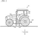
  • FIG. 1 is a side view schematically showing an example of a work vehicle 10.
  • the work vehicle 10 shown in FIG. 1 is a tractor, and a work equipment (implement) can be installed at one or both of the rear and the front.
  • the work vehicle 10 can travel inside a field while performing agricultural work according to the type of the work equipment.
  • the work vehicle 10 may travel inside or outside the field with no work equipment attached thereto.
  • the work vehicle 10 includes a vehicle body 101, an internal combustion engine (engine) 102, and a transmission case 103.
  • the vehicle body 101 is provided with a pair of front wheel 104, a pair of rear wheels 105, and a cabin 106.
  • An internal combustion engine 102 may be a diesel engine, for example.
  • a power transmission device 15 ( FIG. 2 ) is housed in the transmission case 103.
  • a driver's seat 108, a steering device 107, and operation switches are provided inside the cabin 105.
  • one or both of the front wheels 104 and the rear wheels 105 may be a plurality of wheels (crawlers) with an infinite track (track) attached.
  • the steering system 107 includes a steering wheel, a steering shaft connected to the steering wheel, and a power steering device to assist steering by the steering wheel.
  • the front wheels 104 are the steered wheels, such that changing their angle of turn (also referred to as "steering angle") can cause a change in the traveling direction of the work vehicle 10.
  • a linkage device 109 is provided at the rear of the vehicle body 101.
  • the linkage device 109 allows a work equipment (implement) to be attached to and detached from the work vehicle 10.
  • the linkage device 109 includes, for example, a PTO shaft, and it is possible to transmit the power of the internal combustion engine 102 to the work equipment.
  • the work vehicle 10 can make the work equipment perform a predetermined task while pulling the work equipment.
  • the linkage device 109 may be provided at the front of the vehicle body 101. In that case, the work equipment can be connected to the front of the work vehicle 10.
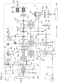
  • FIG. 2 is a view schematically showing the power transmission device 15 of the work vehicle 10.
  • At least a portion of the power transmission device 15 is housed in the transmission case 103 ( FIG. 1 ).
  • the power transmission device 15 transmits the output power of the internal combustion engine 102 to the front wheels 104 and the rear wheels 105.
  • the power transmission device 15 includes an input shaft 20, a main transmission device 21, a forward/backward switching device 23, a gear mechanism 24, a front wheel transmission mechanism 25, a rear wheel differential mechanism 16, and a front wheel differential mechanism 17.
  • the rotation of an output shaft 102a of the internal combustion engine 102 is transmitted to the input shaft 20.
  • the rotation of the output shaft 102a of the internal combustion engine 102 is transmitted to the input shaft 20 via a damper disc, for example.
  • the rotation of the input shaft 20 is transmitted to the main transmission device 21.
  • the main transmission device 21 includes a hydrostatic transmission device (HST: Hydro Static Transmission) 28 and a planetary transmission unit 30.
  • the planetary transmission unit 30 includes a planetary transmission device 31 and a hydraulic clutch mechanism 29.
  • the rotation of the input shaft 20 is transmitted to the HST 28.
  • the rotation of the input shaft 20 and the rotation generated by the HST 28 are transmitted to the planetary transmission device 31.
  • the planetary transmission device 31 generates a plurality of types of rotations corresponding to a plurality of transmission gears.
  • the hydraulic clutch mechanism 29 switches the transmission gear of the planetary transmission device 31, thereby altering its gear ratio.
  • the HST 28 includes a hydraulic pump P, a hydraulic motor M, a pump shaft 28a, an output shaft 28b, and a swash plate 49.
  • a rotating shaft 26 is connected to the rear end portion of the input shaft 20.
  • a first gear mechanism 27A is connected to the rear end portion of the rotating shaft 26.
  • the rotation of the input shaft 20 is transmitted to the pump shaft 28a via the rotating shaft 26 and the first gear mechanism 27A.
  • the pump shaft 28a is connected to the hydraulic pump P, and the rotation of the input shaft 20 is transmitted to the hydraulic pump P.
  • the hydraulic pump P is a variable displacement hydraulic pump.
  • the oil discharged by the hydraulic pump P is supplied to the hydraulic motor M, and the hydraulic motor M generates rotation.
  • the angle of the swash plate 49 it is possible to steplessly change the speed of the rotation generated by the hydraulic motor M.
  • the direction of the rotation generated by the hydraulic motor M can be switched between the forward rotation direction and the reverse rotation direction.
  • the rotation generated by the hydraulic motor M is output from the output shaft 28b.
  • a second gear mechanism 27B is provided between the output shaft 28b and the planetary transmission device 31.
  • the rotation of the output shaft 28B is transmitted to the planetary transmission device 31 via the second gear mechanism 27B.
  • the rotation of the input shaft 20 and the rotation of the output shaft 28b of the HST 28 are transmitted to the planetary transmission device 31.
  • FIG. 3 is a view schematically showing the planetary transmission device 31.
  • the planetary transmission device 31 includes a first planetary transmission device 32 and a second planetary transmission device 33.
  • the planetary transmission device 31 has a composite planetary gear mechanism.
  • the first planetary transmission device 32 includes a first sun gear 32a, a first planetary gear 32b, a first ring gear 32c, and an interlocking gear 32d.
  • the second planetary transmission device 33 includes a second sun gear 33a, a second planetary gear 33b, a second ring gear 33c, and a second carrier 33d.
  • the first sun gear 32a meshes with the first planetary gear 32b. Internal teeth that mesh with the first planetary gear 32b are provided on the first ring gear 32c.
  • the second planetary transmission device 33 is arranged rearward relative to the first planetary transmission device 32.
  • the second sun gear 33a meshes with the second planetary gear 33b. Internal teeth that mesh with the second planetary gear 33b are provided on the second ring gear 33c.
  • the second carrier 33d supports the second planetary gear 33b.
  • the interlocking gear 32d meshes with the first planetary gear 32b.
  • the interlocking gear 32d and the second planetary gear 33b are linked together by a linkage member 33e and are interlocked with each other.
  • the rotation of the output shaft 28b of the HST 28 is transmitted to the first sun gear 32a via the second gear mechanism 27b.
  • a third gear mechanism 27C is provided between the input shaft 20 and the first ring gear 32c. The rotation of the input shaft 20 is transmitted to the first ring gear 32c via the third gear mechanism 27C.
  • the planetary transmission device 31 includes an output device 37 ( FIG. 2 ) that outputs the rotation.
  • the output device 37 includes a first input shaft 34a, a second input shaft 34b, a third input shaft 34c, and an output shaft 35.
  • the first input shaft 34a is connected to the second link gear 33c
  • the second input shaft 34b is connected to the second carrier 33d
  • the third input shaft 34c is connected to the second sun gear 33a.
  • the output device 37 further includes a first range gear mechanism 36a, a second range gear mechanism 36b, a third range gear mechanism 36c, and a fourth range gear mechanism 36d.
  • the hydraulic clutch mechanism 29 includes a first clutch CL1, a second clutch CL2, a third clutch CL3, and a fourth clutch CL4.
  • the first range gear mechanism 36a is connected to the first input shaft 34a and the rotation of the first input shaft 34a is transmitted thereto.
  • the first clutch CL1 is provided between the first range gear mechanism 36a and the output shaft 35. When the first clutch CL1 is engaged, the rotation of the first range gear mechanism 36a is transmitted to the output shaft 35 via the first clutch CL1. When the first clutch CL1 is disengaged, the rotation of the first range gear mechanism 36a is not transmitted to the output shaft 35.
  • the second range gear mechanism 36b is connected to the third input shaft 34c, and the rotation of the third input shaft 34c is transmitted thereto.
  • the second clutch CL2 is provided between the second range gear mechanism 36b and the output shaft 35. When the second clutch CL2 is engaged, the rotation of the second range gear mechanism 36b is transmitted to the output shaft 35 via the second clutch CL2. When the second clutch CL2 is disengaged, the rotation of the second range gear mechanism 36b is not transmitted to the output shaft 35.
  • the third range gear mechanism 36c is connected to the second input shaft 34b, and the rotation of the second input shaft 34b is transmitted thereto.
  • the third clutch CL3 is provided between the third range gear mechanism 36c and the output shaft 35. When the third clutch CL3 is engaged, the rotation of the third range gear mechanism 36c is transmitted to the output shaft 35 via the third clutch CL3. When the third clutch CL3 is disengaged, the rotation of the third range gear mechanism 36c is not limited to the output shaft 35.
  • the fourth range gear mechanism 36d is connected to the third input shaft 34c, and the rotation of the third input shaft 34c is transmitted thereto.
  • the fourth clutch CL4 is provided between the fourth range gear mechanism 36d and the output shaft 35. When the fourth clutch CL4 is engaged, the rotation of the fourth range gear mechanism 36d is transmitted to the output shaft 35 via the fourth clutch CL4. When the fourth clutch CL4 is disengaged, the rotation of the fourth range gear mechanism 36d is not transmitted to the output shaft 35.
  • the rotation of the output shaft 28b of the HST 28 is transmitted to the first sun gear 32a.
  • the rotation of the internal combustion engine 102 is transmitted to the first ring gear 32c via the input shaft 20.
  • the planetary transmission device 31 combines these transmitted rotations, and outputs the combined rotation from the output shaft 35.
  • the rotation of the output shaft 35 is transmitted to the forward/backward switching device 23.
  • the forward/backward switching device 23 includes an input shaft 23a, an output shaft 23b, a forward gear interlocking mechanism 23c, a reverse gear interlocking mechanism 23d, a forward clutch CLF, and a reverse clutch CLR.
  • the rotation of the output shaft 35 is transmitted to the input shaft 23a.
  • the forward clutch CLF and the reverse clutch CLR are provided on the input shaft 23a.
  • the rotation of the output shaft 23b is transmitted to an input shaft 16a of the rear wheel differential mechanism 16 and an input shaft 25a of the front wheel transmission mechanism 25 via the gear mechanism 24.
  • FIG. 2 only shows the left rear wheel 105 of the left and right rear wheels 105.
  • a brake 38A is provided on the output shaft 16b, and the rotation of the output shaft 16b is transmitted to the rear wheels 105 via a planetary deceleration mechanism 38B.
  • the right rear wheel 105 also has the same power transmission structure as the power transmission structure of the left rear wheel 105.
  • the front wheel transmission mechanism 25 includes the input shaft 25a, an output shaft 25b, a constant-speed gear mechanism 40, a speed-increasing gear mechanism 41, a constant-speed clutch CLT, and a speed-increasing clutch CLH.
  • the input shaft 25a is connected to an output shaft 24a of the gear mechanism 24.
  • the rotation of the output shaft 23b of the forward/backward switching device 23 is transmitted to the input shaft 25a.
  • a parking brake 39 is provided on the output shaft 24a of the gear mechanism 24.
  • the constant-speed clutch CLT and the speed-increasing clutch CLH are provided on the input shaft 25a of the front wheel transmission mechanism 25.
  • the power transmission device 15 ( FIG. 2 ) is provided with a plurality of rotation sensors 70 that detect the rotation of various components.
  • the rotational speed (the number of revolutions) of various components can be calculated by using the output signals of these rotation sensors 70.
  • the plurality of rotation sensors 70 includes, for example, a rotation sensor that detects the rotation of the output shaft 28b of the HST 28, a rotation sensor that detects the rotation of the output shaft 35 of the planetary transmission device 31, a rotation sensor that detects the rotation of the output shaft 23b of the forward/backward switching device 23, a rotation sensor that detects the rotation of the input shaft 16a of the rear wheel differential mechanism 16, etc.
  • a rotation sensor 71 that detects the rotation of the internal combustion engine 102 is provided on the internal combustion engine 102.
  • the rotation sensor 71 detects the rotation of the output shaft 102a, for example.
  • the rotational speed of the internal combustion engine 102 can be calculated by using the output signal of the rotation sensor 71.
  • FIG. 4 is a view schematically showing the HST 28.
  • a hydraulic cylinder 90 is connected to the swash plate 49 of the hydraulic pump P.
  • a gearshift operation valve 92 is connected to the hydraulic cylinder 90 via an operation oil channel 91.
  • a hydraulic pump 94 is connected to the gearshift operation valve 92 via an oil feed channel 93.
  • An emergency relief valve 96 and a pressure sensor 97 are provided on a closed circuit 95 that connects together the hydraulic pump P and the hydraulic motor M.
  • the pressure sensor 97 detects the hydraulic pressure in the closed circuit 95.
  • a temperature sensor 74 is provided in the closed circuit 95. By using the temperature sensor 74, it is possible to detect the temperature of the oil supplied to the hydraulic motor M.
  • Hydraulic oil is supplied from the hydraulic pump 94 to the hydraulic cylinder 90 via the gearshift operation valve 92, thereby operating the hydraulic cylinder 90.
  • By operating the hydraulic cylinder 90 it is possible to change the tilt angle of the swash plate 49.
  • the gearshift operation valve 92 is an electromagnetic valve, for example, and the port switching can be performed by operating a solenoid 92a of the gearshift operation valve 92.
  • the HST 28 can change the direction in which the swash plate 49 is tilted by switching the port of the gearshift operation valve 92, and the direction of the rotation generated by the hydraulic motor M can be switched between the forward rotation direction and the reverse rotation direction.
  • the HST 28 can operate the hydraulic cylinder 90 to change the tilt angle of the swash plate 49, thereby steplessly changing the speed of the rotation generated by the hydraulic motor M.
  • the hydraulic cylinder 90 is provided with a position sensor 72 that detects, for example, the position of the cylinder of the hydraulic cylinder 90. Using the output signal of the position sensor 72, it is possible to calculate the tilt direction and tilt angle of the swash plate 49.
  • a sensor for detecting the tilt direction and the tilt angle of the swash plate 49 may be provided on the swash plate 49.
  • FIG. 5A to FIG. 5D are views schematically showing an example of a clutch of the hydraulic clutch mechanism 29 ( FIG. 2 ) .
  • Each of the first to fourth clutches CL1 to CL4 may have a structure of the clutch CL shown in FIG. 5A to FIG. 5D , for example.
  • the clutch CL is provided with a hydraulic chamber 135.
  • a hydraulic pump 141 and an oil tank 142 are connected to the hydraulic chamber 135 via an oil chamber 145.
  • An open/close valve 143 is provided between the hydraulic chamber 135 and the hydraulic pump 141.
  • An open/close valve 144 is provided between the hydraulic chamber 135 and the oil tank 142.
  • the open/close valves 143 and 144 are electromagnetic valves, for example.
  • the hydraulic pump 141 is provided with a temperature sensor 73.
  • the temperature sensor 73 detects the temperature of oil supplied to the hydraulic chamber 135. There is no limitation on the position at which the temperature sensor 73 is provided.
  • FIG. 5A shows the disengaged state of the clutch CL. If the open/close valve 143 is opened and the open/close valve 144 is closed while the clutch CL is disengaged, oil is supplied from the hydraulic pump 141 to the hydraulic chamber 135, a piston 133 moves in the direction of the arrow 137 while pushing a plate 131 as shown in FIG. 5B . As the piston 133 moves in the direction of the arrow 137 while pushing the plate 131, the plate 131 comes into contact with a plate 132, as shown in FIG. 5C , thereby bringing the clutch CL into the engaged state.
  • the detection of contact between the plate 131 and the plate 132 can be done by using a pressure sensor 136, for example.
  • the work vehicle 10 includes a control system that controls the operation of the work vehicle 10.
  • FIG. 6 is a block diagram showing an example of a control system 200 of the work vehicle 10.
  • FIG. 6 shows elements that are relatively more relevant to the gearshift operation of the work vehicle 10, and other elements are omitted from the illustration.
  • the control system 200 includes a controller 210 and a storage device 220.
  • the controller 210 can be realized by a computer including a processor, such as an electronic control unit (ECU), provided in the work vehicle 10.
  • the controller 210 may be realized by a single ECU or by a plurality of ECUs. For example, where the controller 210 is realized by a plurality of ECUs, those ECUs may be distributed in the work vehicle 10.
  • a portion of the controller 210 may be realized by a user terminal device and/or a server computer, etc., capable of communicating with the work vehicle 10.
  • the controller 210 controls the operation of the power transmission device 15 based on the user operation on an operation device 120 and output signals of the sensors 70 to 74.
  • the operation device 120 includes a speed pedal 121, a forward/backward lever 122, and other devices operated by the user.
  • the controller 210 controls the travel speed of the work vehicle 10 in accordance with the amount by which the speed pedal 121 is operated by the user, and switches forward/backward of the work vehicle 10 in response to the user operating the forward/backward lever 122.
  • the storage device 220 is a storage device including any storage medium, such as, for example, a semiconductor storage medium, a magnetic storage medium, or an optical storage medium.
  • the storage device 220 may be a collection of storage devices.
  • the storage device 220 may be a device independent of the controller 210 or may be included in the controller 210. For example, when an ECU functions as the controller 210, the memory included in the ECU may function as the storage device 220.
  • the storage device 220 stores computer programs executed by the controller 120 and various information generated by the controller 120.
  • FIG. 7 is a view showing an example of a gearshift operation of the work vehicle 10.
  • the vertical axis of FIG. 7 represents the ratio ⁇ .
  • the ratio ⁇ is the ratio between the rotational speed of the internal combustion engine 102 to the rotational speed of a predetermined component on the power transmission path for transmitting the rotation of the output shaft 35 of the planetary transmission device 31 to the wheels 104 and 105 and the rotational speed of the internal combustion engine 102.
  • the predetermined component may be any component existing between the output shaft 35 and the wheels 104 and 105, and can be, for example, but not limited to, the input shaft 16a and the output shaft 23b shown in FIG. 2 .
  • the predetermined component may be any of the output shafts 35 and the wheels 104 and 105. As an example, it is assumed herein that the predetermined component is the input shaft 16a. Where the rotational speed of the internal combustion engine 102 is constant, the traveling speed of the work vehicle 10 increases as the ratio ⁇ increases.
  • the horizontal axis of FIG. 7 represents the state of the HST 28.
  • N represents the neutral state of the HST 28, where the swash plate 49 is in the neutral position.
  • +MAX represents the state of the HST 28 in which the hydraulic motor M generates rotation in the forward rotation direction at the maximum speed, and the swash plate 49 is tilted significantly to the side corresponding to the forward rotation.
  • -MAX represents the state of the HST 28 in which the hydraulic motor M generates rotation in the reverse rotation direction at the maximum speed, and the swash plate 49 is tilted significantly to the side corresponding to the reverse rotation.
  • +K represents the state of the HST 28 at the point where the transmission gear of the planetary transmission device 31 is switched on the forward rotation side.
  • -K represents the state of the HST 28 at the point where the transmission gear of the planetary transmission device 31 is switched on the reverse rotation side.
  • Switching points S1, S2 and S3 are the points at which the transmission gear of the planetary transmission device 31 is switched.
  • the storage device 220 stores in advance data indicating the relationship between the ratio ⁇ and the switching points S1, S2 and S3.
  • the data includes, for example, information regarding the ratio ⁇ 1 corresponding to the switching point S1, the ratio ⁇ 2 corresponding to the switching point S2, and the ratio ⁇ 3 corresponding to the switching point S3.
  • the controller 210 reads that data from the storage device 220.
  • the controller 210 controls switching of the transmission gear of the planetary transmission device 31 based on the readout data and the detected value of the ratio ⁇ .
  • the controller 210 can change the tilt angle of the swash plate 49 by, for example, controlling the operation of the gearshift operation valve 92 ( FIG. 4 ) of the HST 28.
  • the speed at which the swash plate 49 is tilted can be controlled by, for example, using a flow control valve.
  • the controller 210 can switch between the engaged state and the disengaged state of each of the clutches CL1 to CL4 by, for example, controlling the operation of the open/close valves 143 and 144 ( FIG. 5A to FIG. 5D ) .
  • the controller 210 controls the swash plate 49 to be at a tilt angle corresponding to "-K" and also controls the hydraulic clutch mechanism 29 so that the first clutch CL1 is engaged.
  • the controller 210 changes the tilt angle of the swash plate 49 from the "-MAX" side toward the "+MAX” side.
  • the controller 210 controls the internal combustion engine 102 so that the rotational speed of the internal combustion engine 102 is constant.
  • the tilt angle of the swash plate 49 changes, the rotational speed of the reverse rotation generated by the hydraulic motor M gradually decreases, and the rotational speed becomes zero at the neutral position.
  • the hydraulic motor M By further changing the tilt angle of the swash plate 49 from the neutral position toward the "+MAX" side, the hydraulic motor M generates rotation in the forward rotation direction, and the rotational speed of the forward rotation generated by the hydraulic motor M gradually increases. In the process of thus changing the tilt angle of the swash plate 49, the ratio ⁇ increases steplessly.
  • the controller 210 causes the second clutch CL2 to be engaged and the first clutch CL1 to be disengaged.
  • the transmission gear of the planetary transmission device 31 switches from the first gear to the second gear.
  • the fact that the state of the HST 28 has reached the switching points S1 to S3 can be detected, for example, from the value of the ratio ⁇ and/or the tilt angle of the swash plate 49.
  • the controller 210 changes the tilt angle of the swash plate 49 from the "+MAX" side toward the "-MAX” side.
  • the ratio ⁇ increases steplessly.
  • the controller 210 causes the third clutch CL3 to be engaged and the second clutch CL2 to be disengaged. As a result, the transmission gear of the planetary transmission device 31 switches from the second gear to the third gear.
  • the controller 210 changes the tilt angle of the swash plate 49 from the "-MAX" side toward the "+MAX” side.
  • the ratio ⁇ increases steplessly.
  • the controller 210 causes the fourth clutch CL4 to be engaged and the third clutch CL3 to be disengaged. As a result, the transmission gear of the planetary transmission device 31 switches from the third gear to the fourth gear.
  • the controller 210 changes the tilt angle of the swash plate 49 from the "+MAX" side toward the "-MAX” side.
  • the ratio ⁇ increases steplessly.
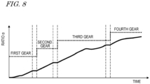
  • FIG. 8 is a view showing an example of the ratio ⁇ changing in response to the operation of the speed pedal 121 by the user. During the period of switching the transmission gear of the planetary transmission device 31, the change in the ratio ⁇ becomes constant or the value of the ratio ⁇ decreases.
  • the hydraulic chamber 135 ( FIG. 5A to FIG. 5D ) of the clutch is charged with oil.
  • the hydraulic chamber 135 ( FIG. 5A to FIG. 5D ) of the clutch is charged with oil.
  • the oil charging to engage the clutch of the next transmission gear is started before the ratio ⁇ reaches the value corresponding to the switching point.
  • the switching of the transmission gear can be completed in a short amount of time when the ratio ⁇ reaches the value corresponding to the switching point, thereby reducing the shift shock to be felt by the user.
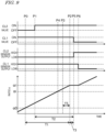
  • FIG. 9 is a graph illustrating the operation of switching the transmission gear of the planetary transmission device 31.
  • the operation of switching the transmission gear of the planetary transmission device 31 from the first gear to the second gear will be described here.
  • the operation of switching between other transmission gears is the same.
  • This operation of switching the transmission gear can also be applied to the operation of lowering the transmission gear (e.g., from the second gear to the first gear).
  • CL2 valve shown in FIG. 9 represents the state of the open/close valves 143 and 144 of the second clutch CL2 ( FIG. 5A to FIG. 5D ) .
  • CL2 valve being “ON” indicates a state where the open/close valve 143 of the second clutch CL2 is open and the open/close valve 144 is closed. Oil is supplied from the hydraulic pump 141 to the hydraulic chamber 135, and the second clutch CL2 becomes engaged.
  • CL2 valve being “OFF” indicates a state where the open/close valve 143 of the second clutch CL2 is closed and the open/close valve 144 is open. Oil in the hydraulic chamber 135 is discharged to the oil tank 142, and the second clutch CL2 becomes disengaged.
  • CL1 valve represents the state of the open/close valves 143 and 144 of the first clutch CL1.
  • CL1 valve being “ON” indicates a state where the open/close valve 143 of the first clutch CL1 is open and the open/close valve 144 is closed. Oil is supplied from the hydraulic pump 141 to the hydraulic chamber 135, and the first clutch CL1 becomes engaged.
  • CL1 valve being “OFF” indicates a state where the open/close valve 143 of the first clutch CL1 is closed and the open/close valve 144 is open. Oil in the hydraulic chamber 135 is discharged to the oil tank 142, and the first clutch CL1 becomes disengaged.
  • CL2 sensor output represents the output signal of the pressure sensor 136 of the second clutch CL2.
  • CL2 sensor output indicates “HIGH” when the second clutch CL2 is engaged, and “CL2 sensor output” indicates “LOW” when the second clutch CL2 is disengaged.
  • CL1 sensor output represents the output signal of the pressure sensor 136 of the first clutch CL1.
  • CL1 sensor output indicates “HIGH” when the first clutch CL1 is engaged, and “CL1 sensor output” indicates “LOW” when the first clutch CL1 is disengaged.
  • the horizontal axis of the graph shown in the lower half of FIG. 9 represents time, and the vertical axis represents the ratio ⁇ .
  • This graph shows the change in the ratio ⁇ when the transmission gear of the planetary transmission device 31 is switched from the first gear to the second gear.
  • the transmission gear is switched when the ratio ⁇ changes to reach the first value ⁇ 1 (the ratio ⁇ 1) corresponding to the switching point S1 or after the ratio ⁇ has reached the first value ⁇ 1. Then, the controller 210 controls the hydraulic clutch mechanism 29 to start the oil charging for switching the transmission gear before the ratio ⁇ reaches the first value ⁇ 1.
  • the controller 210 estimates the time period T1 (first time period) required for the ratio ⁇ to reach the first value ⁇ 1 from the current value. Based on the estimated time period T1, the controller 210 can start the oil charging to the hydraulic chamber 135 of the second clutch CL2 before the ratio ⁇ reaches the first value ⁇ 1.
  • the controller 210 obtains the value of the time period T2 (second time period) required before the second clutch CL2 is engaged since the start of the oil charging for switching from the current transmission gear (first gear) to the next transmission gear (second gear).
  • the controller 210 can determine, based on the time period T2, the time point P1 (first time point) to start the oil charging for switching the transmission gear.
  • the controller 210 periodically calculates the value of the ratio ⁇ using output signals of sensors 70 and 71.
  • the controller 210 can estimate the time period T1 based on the amount of change of the ratio ⁇ per unit time, the current value of the ratio ⁇ and the first value ⁇ 1. For example, if the time period T1 from the amount of change in the ratio ⁇ per unit time is estimated at a certain time point P0, it is possible to estimate that the ratio ⁇ reaches the first value ⁇ 1 at the time point P2.
  • the amount of change in the ratio ⁇ per unit time may be an average value over a certain period.
  • the time period T1 can be regarded as being a segment from the ratio ⁇ 0, which corresponds to the start point of the time period T1 (time point P0), to the ratio ⁇ 1, and the controller 210 starts the oil charging to the hydraulic chamber 135 of the second clutch CL2 within the segment from the ratio ⁇ 0 to the ratio ⁇ 1.
  • a period (segment) over which the operation of switching the valve from “OFF” to “ON” is performed may be determined based on the values of the ratios ⁇ 1 to ⁇ 3 that change depending on whether or not a work equipment is connected, the current transmission gear of the planetary transmission device 31, and the amount of time since when the valve is turned “ON” until the output signal of the pressure sensor 136 indicates "HIGH".
  • the time period T1 (or the segment from the ratio ⁇ 0 to the ratio ⁇ 1) is a period (or segment) over which the operation of switching the valve from "OFF" to “ON” is performed.
  • the controller 210 controls the second clutch CL2 so that the second clutch CL2 is engaged at the same time as, or after elapse of a predetermined time period T3 (second predetermined time period) since, the ratio ⁇ reaching the first value ⁇ 1 (the ratio ⁇ 1). While the predetermined time period T3 is 1 to 20 milliseconds, for example, there is no limitation thereto. The predetermined time period T3 may be zero.
  • the time period T2 from the start of the oil charging to the second clutch CL2 being disengaged to when the second clutch CL2 is engaged is predetermined, and data of the time period T2 is stored in the storage device 220.
  • the controller 210 can determine the time point P1 at which to start the oil charging to the second clutch CL2 based on the time periods T1, T2 and T3, for example.
  • the time period Ta since when the valve is turned “ON” until the output signal of the pressure sensor 136 indicates "HIGH” may be measured in advance, and the measured time period Ta may be stored in the storage device 220.
  • the time period T1 and the time period Ta may be compared with each other, and the controller 210 may start the oil charging to the hydraulic chamber 135 of the second clutch CL2 when the time period T1 becomes shorter than the time period Ta.
  • the output signal of the pressure sensor 136 may not indicate "HIGH” when the time period Ta elapses since when the valve is turned ON. Therefore, a certain amount of time period T3 may be provided as a margin to determine the timing (time point P1) at which to turn the valve ON.
  • the controller 210 opens the open/close valve 143 of the second clutch CL2 and closes the open/close valve 144. This starts supplying oil to the hydraulic chamber 135 of the second clutch CL2 from the hydraulic pump 141.
  • the ratio ⁇ reaches the first value ⁇ 1 at the time point P2, and the second clutch CL2 is engaged at the time point P5.
  • the output signal of the pressure sensor 136 of the second clutch CL2 changes from "LOW” to "HIGH”.
  • the controller 210 disengages the first clutch CL1.
  • the controller 210 closes the open/close valve 143 of the first clutch CL1 and opens the open/close valve 144. Oil in the hydraulic chamber 135 of the first clutch CL1 starts to be discharged, and the first clutch CL1 is disengaged at the time point P6.
  • the time period T2 from the start of the oil charging to the second clutch CL2 being disengaged until when the second clutch CL2 is engaged may be changed depending on the state of the second clutch CL2.
  • the controller 210 changes the length of the time period T2 based on the elapsed time since when the second clutch CL2 is disengaged after being previously engaged.
  • the controller 210 sets the time period T2 to be short.
  • the time period T4 (first predetermined time period) since when the control of disengaging the second clutch CL2 being engaged is started until the oil of the hydraulic chamber 135 drains out is predetermined.
  • the controller 210 sets the time period T2 to be shorter when the elapsed time is less than the time period T4 than when the elapsed time is equal to or greater than the time period T4. Therefore, it is possible to suppress the second clutch CL2 from being engaged before the ratio ⁇ reaches the first value ⁇ 1.
  • setting the time period T2 to be short can be regarded as bringing the ratio ⁇ , which corresponds to the start point of the time period T2 (the time point P1 at which to start the oil charging to the second clutch CL2 being disengaged), closer to the first value ⁇ 1.
  • the time period T4 may be changed in accordance with the temperature of the oil supplied to the hydraulic chamber 135.
  • the temperature of the oil supplied to the hydraulic chamber 135 can be detected by using the temperature sensor 73.
  • the controller 210 may set the time period T4 to be shorter when the temperature of the oil to be charged for engaging the second clutch CL2 is higher than when it is lower.
  • the switching of the transmission gear may be discontinued before the ratio ⁇ reaches the first value ⁇ 1.
  • the amount of change in the ratio ⁇ per unit time may decrease due to factors such as the user relaxing the operation of the speed pedal 121 or an increase in the load on the work vehicle 10. If it is determined that the ratio ⁇ no longer reaches the first value ⁇ 1 at the time point P2 based on the calculated amount of change in the ratio ⁇ per unit time, the controller 210 discontinues the switching of the transmission gear.
  • the controller 210 may set a reference time point P3 (third time point), and may determine whether or not to discontinue the switching of the transmission gear before the time point P3 and not determine again whether or not to discontinue the switching of the transmission gear after the time point P3.
  • the controller 210 sets, as the time point P3, a time point that is a predetermined time period T5 (third predetermined time period) before the time point P2. While the predetermined time period T5 is 20 to 50 milliseconds, for example, there is no limitation thereto.
  • the controller 210 discontinues the switching of the transmission gear.
  • the controller 210 When it is determined not to discontinue the switching of the transmission gear past the time point P3, the controller 210 performs the switching of the transmission gear. For example, the controller 210 performs the switching of the transmission gear even if a factor to discontinue the switching of the transmission gear as described above occurs during a period of time from after the time point P3 and before reaching the time point P2. This reduces the faltering of the control process.
  • the controller 210 determines whether or not to perform switching back to the original transmission gear (first gear). For example, if the ratio ⁇ after the switching of the transmission gear is performed is smaller than the first value ⁇ 1 by a predetermined value or more, the controller 210 switches the transmission gear back to the first gear. If the ratio ⁇ after the switching of the transmission gear is performed is not smaller than the first value ⁇ 1 by a predetermined value or more, the switched transmission gear (second gear) is maintained.
  • the controller 210 may change the length of the predetermined time period T5 in accordance with the temperature of the oil to be charged into the second clutch CL2 to perform the switching of the transmission gear. For example, the controller 210 sets the predetermined time period T5 to be longer when the temperature of the oil to be charged into the second clutch CL2 is high than when the temperature is low. That is, the time point P3 is set at an earlier time point when the temperature of the oil is high than when the temperature is low. When the oil is hot, the viscosity may be small and the oil charging may be faster. By setting the time point P3 at an earlier time point, it is possible to perform a smooth control even if the second clutch CL2 is engaged early.
  • the tilt angle of the swash plate 49 changes continuously. Then, the swash plate 49 has an inertia acting thereon in the direction of changing the tilt angle. Therefore, even if the control to change the tilt angle of the swash plate 49 in the forward rotation direction is stopped when the ratio ⁇ changes to reach the first value ⁇ 1, the tilt angle of the swash plate 49 may continue to change in the forward rotation direction due to inertia. If the tilt angle of the swash plate 49 continues to change to the forward rotation side, acceleration after switching the transmission gear to the second gear may not be smooth.
  • the control of changing the tilt angle of the swash plate 49 to the forward rotation side may be stopped before the ratio ⁇ reaches the first value ⁇ 1.
  • the tilt angle ⁇ 1 of the swash plate 49 when the ratio ⁇ is the first value ⁇ 1 is predetermined.
  • the value of the tilt angle ⁇ 1 may be predetermined by the controller 210.
  • the controller 210 stops the control to change the tilt angle of the swash plate 49 to the forward rotation side.
  • Data indicating the relationship between the tilt angle of the swash plate 49 and the ratio ⁇ is stored in advance in the storage device 220. Based on that data, the controller 210 can determine the value of the ratio ⁇ i when the tilt angle of the swash plate 49 is ⁇ 3. The value of the ratio ⁇ i may be stored in advance in the storage device 220. In the process of the ratio ⁇ changing to approach the first value ⁇ 1, the controller 210 stops the control of changing the tilt angle of the swash plate 49 to the positive rotation side at the time point P4 when the ratio ⁇ becomes equal to the ratio ⁇ i.
  • the controller 210 may change the time point P4 at which the control is stopped based on the amount of change in the ratio ⁇ per unit time. For example, the controller 210 sets the time point P4 to an earlier time point when the amount of change in the ratio ⁇ per unit time is greater than when it is smaller. If the amount of change in the ratio ⁇ per unit time is large, the inertia acting on the swash plate 49 is large and the amount of overrun of the swash plate 49 may be large. When the amount of change in the ratio ⁇ per unit time is large, it is possible to suppress the overrun of the swash plate 49 by stopping the control of changing the tilt angle of the swash plate 49 to the positive rotation side earlier.
  • the controller 210 stops the control of changing the tilt angle of the swash plate 49 to the positive rotation side, thereby suppressing the overrun of the swash plate 49.
  • Data indicating the relationship between the amount of change in the ratio ⁇ per unit time and the angles ⁇ 2 and ⁇ 3 may be stored in advance in the storage device 220.
  • Data indicating the relationship between the amount of change in the ratio ⁇ per unit time and the ratio ⁇ i may be stored in advance in the storage device 220.
  • the controller 210 may use these data to stop the control of changing the tilt angle of the swash plate 49 to the positive rotation side.
  • the controller 210 may change the time point P4 based on the temperature of the oil supplied to the hydraulic motor M. For example, the controller 210 may set the time point P4 to an earlier time point when the temperature of the oil supplied to the hydraulic motor M is higher than when the temperature is lower.
  • the viscosity may become small, and the amount of overrun of the swash plate 49 may become large.
  • the controller 210 may change the time point P4 in accordance with the pressure of the closed circuit 95 of the HST 28. For example, if the swash plate 49 is under a force (internal pressure) in the direction of being swept (the direction of being driven around from behind), the time point P4 may be set to an earlier time point, and if the swash plate 49 is under a force in the direction of being pushed back (the direction of being stopped from the front by the brake), the time point P4 may be set to a later time point. Thus, it is possible to appropriately control the overrun of the swash plate 49.
  • the work vehicle 10 may have a self-driving function.
  • the techniques of the present disclosure can also be applied to the switching of the transmission gear in self-driving.
  • ECU1 that monitors the operation of the speed pedal 121 by the user and an ECU (ECU2) that switches the transmission gear may be provided separately.
  • ECU1 may send a command to ECU2 to switch the transmission gear based on the state of operation of the speed pedal 121, and ECU2, having received the command, may start preparing to switch the transmission gear.
  • ECU2 may start calculating the amount of change in the ratio ⁇ per unit time after receiving the command, thereby reducing the total amount of calculation.
  • a control system including the controller and the storage device of the embodiment described above may be installed later on the work vehicle. Such a system may be manufactured and sold independently of the work vehicle.
  • the computer program used in such a system may also be manufactured and sold independently of the work vehicle.
  • the computer program may be provided, for example, stored on a computer-readable, non-transitory storage medium.
  • the computer program may also be provided by downloading via a telecommunication line (e.g., the Internet).
  • control systems As described above, the present disclosure includes control systems, work vehicles, control methods and computer programs as set forth in the following items.
  • a control system for controlling an operation of a power transmission device of a work vehicle wherein:
  • controller estimates the first time period based on an amount of change in the ratio per unit time.
  • the controller determines a first time point at which to start the oil charging for performing switching of the transmission gear based on a second time period required before a clutch of the next transmission gear is engaged since the start of the oil charging for performing switching of the transmission gear.
  • control system determines a length of the second time period based on elapsed time since the clutch of the next transmission gear is disengaged after being previously engaged.
  • control system wherein the controller sets the second time period to be shorter when the elapsed time is shorter than a first predetermined time period than when the elapsed time is longer than the first predetermined time period.
  • the control system according to item 5, wherein the controller sets the first predetermined time period to be shorter when a temperature of oil to be charged for engaging the clutch of the next transmission gear is a first temperature than when the temperature is a second temperature, which is lower than the first temperature.
  • control system determines the first time point to start the oil charging so that the clutch of the next transmission gear is engaged at the same time as the ratio reaches the first value or after elapse of a second predetermined time period since the ratio reaches the first value.
  • control system wherein the controller performs a control of disengaging the clutch of the transmission gear before being switched after the ratio reaches the first value.
  • control system wherein the controller performs switching of the transmission gear even if a factor to discontinue switching of the transmission gear during a period of time from after the third time point and before reaching the second time point.
  • control system according to item 12, wherein after switching of the transmission gear is performed, the controller determines whether or not to perform switching back to the original transmission gear.
  • control system according to item 10, wherein the controller changes the third predetermined time period in accordance with a temperature of the oil to be charged for performing switching of the transmission gear.
  • control system wherein the controller sets the third predetermined time period longer when the temperature of the oil to be charged for performing switching of the transmission gear is a third temperature than when the temperature is a fourth temperature, which is lower than the third temperature.
  • control system according to item 16, wherein the controller changes a fourth time point at which to stop the control of changing the angle of the swash plate based on an amount of change in the ratio per unit time.
  • controller sets the fourth time point to an earlier time point if the amount of change in the ratio per unit time is a first amount of change than when the amount of change in the ratio per unit time is a second amount of change, which is smaller than the first amount of change.
  • control system according to item 17, wherein the controller changes the fourth time point based further on a temperature of the oil supplied to the hydraulic motor.
  • a work vehicle including the control system, the internal combustion engine and the power transmission device according to any one of items 1 to 20.
  • a control method for controlling an operation of a power transmission device of a work vehicle wherein:
  • a computer program causing a computer to control an operation of a power transmission device of a work vehicle, wherein:
  • a control system for controlling an operation of a power transmission device of a work vehicle wherein:
  • control system wherein the controller changes a length of the time period required before the clutch of the next transmission gear is engaged since the start of the oil charging based on elapsed time since the clutch of the next transmission gear is disengaged after being previously engaged.
  • control system wherein the controller sets the time period required before the clutch of the next transmission gear is engaged since the start of the oil charging to be shorter when the elapsed time is shorter than a first predetermined time period than when the elapsed time is longer than the first predetermined time period.
  • control system determines the time point at which to start the oil charging so that the clutch of the next transmission gear is engaged at the same time as the ratio reaches the first value or after elapse of a second predetermined time period since the ratio reaches the first value.
  • control system according to item 28, wherein the controller performs a control of disengaging the clutch of the transmission gear before being switched after the ratio reaches the first value.
  • a control system for controlling an operation of a power transmission device of a work vehicle wherein:
  • a work vehicle including the control system, the internal combustion engine and the power transmission device according to any one of items 24 to 31.
  • the techniques of the present disclosure are useful particularly in the technical field of transmission devices of vehicles.
Landscapes

  • Engineering & Computer Science (AREA)
  • General Engineering & Computer Science (AREA)
  • Mechanical Engineering (AREA)
  • Physics & Mathematics (AREA)
  • Fluid Mechanics (AREA)
  • Oil, Petroleum & Natural Gas (AREA)
  • Control Of Transmission Device (AREA)
  • Control Of Fluid Gearings (AREA)

Abstract

A control system controls an operation of a power transmission device of a work vehicle. The control system includes: a storage device to store data indicating a relationship between a ratio between a rotational speed of a predetermined component on a power transmission path for transmitting the rotation of the planetary transmission device to wheels and a rotational speed of the internal combustion engine, and a plurality of switching points, which are points at which the transmission gear of the planetary transmission device is switched; and a controller to control the hydraulic clutch mechanism so as to perform switching of the transmission gear. Where the transmission gear is switched when the ratio changes to reach a first value corresponding to a first switching point or after the ratio reaches the first value, the controller controls the hydraulic clutch mechanism so as to start oil charging for performing switching of the transmission gear before the ratio reaches the first value.

Description

    BACKGROUND 1. Technical Field:
  • The present disclosure relates to a control system, a work vehicle, a control method and a computer program.
  • 2. Description of the Related Art:
  • Examples of work vehicles such as agricultural tractors include work vehicles having an internal combustion engine and a hydrostatic transmission device (see, for example, Japanese Laid-Open Patent Publication No. 2022-96208 ) . The rotation generated by the internal combustion engine and the rotation generated by the hydrostatic transmission device are combined in the planetary transmission device and transmitted to the wheels. The switching of the transmission gear of the planetary transmission device can be performed using a clutch mechanism.
  • SUMMARY
  • If it takes time to switch the transmission gear of the planetary transmission device while the work vehicle is traveling, the user may feel a significant shift shock.
  • There is a need to reduce the amount of time taken to switch the transmission gear.
  • A control system according to one embodiment of the present disclosure is a control system for controlling an operation of a power transmission device of a work vehicle, wherein: the power transmission device includes: a hydrostatic transmission device including a hydraulic pump to which rotation generated by an internal combustion engine is transmitted to thereby discharge oil in accordance with an angle of a swash plate, and a hydraulic motor to which the oil is supplied from the hydraulic pump to thereby generate rotation; a planetary transmission device to which the rotation generated by the internal combustion engine and the rotation generated by the hydrostatic transmission device are transmitted to thereby generate multiple types of rotations corresponding to a plurality of gear ratios; and a hydraulic clutch mechanism to switch the transmission gear of the planetary transmission device; the control system includes: a storage device to store data indicating a relationship between a ratio between a rotational speed of a predetermined component on a power transmission path for transmitting the rotation of the planetary transmission device to wheels and a rotational speed of the internal combustion engine, and a plurality of switching points, which are points at which the transmission gear of the planetary transmission device is switched; and a controller to control the hydraulic clutch mechanism so as to perform switching of the transmission gear based on the ratio and the data; the plurality of switching points include a first switching point; and the controller: when the ratio changes to approach a first value corresponding to the first switching point, estimates a first time period required for the ratio to reach the first value; and controls the hydraulic clutch mechanism so as to start oil charging for performing switching of the transmission gear before the ratio reaches the first value based on the estimated first time period.
  • A control method according to one embodiment of the present disclosure is a control method for controlling an operation of a power transmission device of a work vehicle, wherein: the power transmission device includes: a hydrostatic transmission device including a hydraulic pump to which rotation generated by an internal combustion engine is transmitted to thereby discharge oil in accordance with an angle of a swash plate, and a hydraulic motor to which the oil is supplied from the hydraulic pump to thereby generate rotation; a planetary transmission device to which the rotation generated by the internal combustion engine and the rotation generated by the hydrostatic transmission device are transmitted to thereby generate multiple types of rotations corresponding to a plurality of gear ratios; and a hydraulic clutch mechanism to switch the transmission gear of the planetary transmission device; the control method includes: controlling the hydraulic clutch mechanism so as to perform switching of the transmission gear based on a relationship between a ratio between a rotational speed of a predetermined component on a power transmission path for transmitting the rotation of the planetary transmission device to wheels and a rotational speed of the internal combustion engine, and a plurality of switching points, which are points at which the transmission gear of the planetary transmission device is switched; the plurality of switching points include a first switching point; and the control method further includes: when the ratio changes to approach a first value corresponding to the first switching point, estimating a first time period required for the ratio to reach the first value; and controlling the hydraulic clutch mechanism so as to start oil charging for performing switching of the transmission gear before the ratio reaches the first value based on the estimated first time period.
  • A computer program according to one embodiment of the present disclosure is a computer program causing a computer to control an operation of a power transmission device of a work vehicle, wherein: the power transmission device includes: a hydrostatic transmission device including a hydraulic pump to which rotation generated by an internal combustion engine is transmitted to thereby discharge oil in accordance with an angle of a swash plate, and a hydraulic motor to which the oil is supplied from the hydraulic pump to thereby generate rotation; a planetary transmission device to which the rotation generated by the internal combustion engine and the rotation generated by the hydrostatic transmission device are transmitted to thereby generate multiple types of rotations corresponding to a plurality of gear ratios; and a hydraulic clutch mechanism to switch the transmission gear of the planetary transmission device; the computer program causes the computer to perform: controlling the hydraulic clutch mechanism so as to perform switching of the transmission gear based on a relationship between a ratio between a rotational speed of a predetermined component on a power transmission path for transmitting the rotation of the planetary transmission device to wheels and a rotational speed of the internal combustion engine, and a plurality of switching points, which are points at which the transmission gear of the planetary transmission device is switched; the plurality of switching points include a first switching point; and the computer program causes the computer to further perform: when the ratio changes to approach a first value corresponding to the first switching point, estimating a first time period required for the ratio to reach the first value; and controlling the hydraulic clutch mechanism so as to start oil charging for performing switching of the transmission gear before the ratio reaches the first value based on the estimated first time period.
  • A control system according to one embodiment of the present disclosure is a control system for controlling an operation of a power transmission device of a work vehicle, wherein: the power transmission device includes: a hydrostatic transmission device including a hydraulic pump to which rotation generated by an internal combustion engine is transmitted to thereby discharge oil in accordance with an angle of a swash plate, and a hydraulic motor to which the oil is supplied from the hydraulic pump to thereby generate rotation; a planetary transmission device to which the rotation generated by the internal combustion engine and the rotation generated by the hydrostatic transmission device are transmitted to thereby generate multiple types of rotations corresponding to a plurality of gear ratios; and a hydraulic clutch mechanism to switch the transmission gear of the planetary transmission device; the control system includes: a storage device to store data indicating a relationship between a ratio between a rotational speed of a predetermined component on a power transmission path for transmitting the rotation of the planetary transmission device to wheels and a rotational speed of the internal combustion engine, and a plurality of switching points, which are points at which the transmission gear of the planetary transmission device is switched; and a controller to control the hydraulic clutch mechanism so as to perform switching of the transmission gear based on the ratio and the data; the plurality of switching points include a first switching point; where the transmission gear is switched when the ratio reaches a first value corresponding to the first switching point or after the ratio reaches the first value, the controller controls the hydraulic clutch mechanism so as to start oil charging for performing switching of the transmission gear before the ratio reaches the first value; and the controller determines a time point at which to start the oil charging for performing switching of the transmission gear based on a time period required before a clutch of a next transmission gear is engaged since the start of the oil charging for performing switching from a current transmission gear to the next transmission gear.
  • A control system according to one embodiment of the present disclosure is a control system for controlling an operation of a power transmission device of a work vehicle, wherein: the power transmission device includes: a hydrostatic transmission device including a hydraulic pump to which rotation generated by an internal combustion engine is transmitted to thereby discharge oil in accordance with an angle of a swash plate, and a hydraulic motor to which the oil is supplied from the hydraulic pump to thereby generate rotation; a planetary transmission device to which the rotation generated by the internal combustion engine and the rotation generated by the hydrostatic transmission device are transmitted to thereby generate multiple types of rotations corresponding to a plurality of gear ratios; and a hydraulic clutch mechanism to switch the transmission gear of the planetary transmission device; the control system includes: a storage device to store data indicating a relationship between a ratio between a rotational speed of a predetermined component on a power transmission path for transmitting the rotation of the planetary transmission device to wheels and a rotational speed of the internal combustion engine, and a plurality of switching points, which are points at which the transmission gear of the planetary transmission device is switched; and a controller to control the hydraulic clutch mechanism so as to perform switching of the transmission gear based on the ratio and the data; the plurality of switching points include a first switching point; and the controller: predetermines an angle of the swash plate at the first switching point; performs a control of changing the angle of the swash plate, thereby changing a rotational speed of rotation generated by the hydraulic motor; and when the ratio changes to approach a first value corresponding to the first switching point, stops the control of changing the angle of the swash plate before the ratio reaches the first value.
  • When switching the transmission gear, it takes time to charge oil to engage the clutch of the next target transmission gear. If the oil charging is started after the ratio between the rotational speed of the predetermined rotating component and the rotational speed of the internal combustion engine reaches the value corresponding to a switching point, the user may feel a significant shift shock because it takes time to engage the clutch of the next target transmission gear and the amount of time required to stop the change of the ratio is long.
  • According to an embodiment of the present disclosure, oil charging is started before the ratio reaches the value corresponding to the switching point. Thus, the switching of the transmission gear can be completed in a short amount of time when the ratio reaches the value corresponding to the switching point, thus shortening the amount of time required to stop the change of the ratio, thereby reducing the shift shock to be felt by the user.
  • BRIEF DESCRIPTION OF THE DRAWINGS
    • FIG. 1 is a side view schematically showing an example of a work vehicle.
    • FIG. 2 is a view schematically showing a power transmission device of the work vehicle.
    • FIG. 3 is a view schematically showing a planetary transmission device.
    • FIG. 4 is a view schematically showing a hydrostatic transmission device.
    • FIG. 5A is a view schematically showing an example of a clutch of a hydraulic clutch mechanism.
    • FIG. 5B is a view schematically showing an example of a clutch of the hydraulic clutch mechanism.
    • FIG. 5C is a view schematically showing an example of a clutch of the hydraulic clutch mechanism.
    • FIG. 5D is a view schematically showing an example of a clutch of the hydraulic clutch mechanism.
    • FIG. 6 is a block diagram showing an example of a control system of the work vehicle.
    • FIG. 7 is a view showing an example of a gearshift operation of the work vehicle.
    • FIG. 8 is a graph showing a ratio that changes in response to the operation of a speed pedal by the user.
    • FIG. 9 is a graph illustrating an operation of switching the transmission gear of the planetary transmission device.
    DETAILED DESCRIPTION
  • A control system and a work vehicle including the control system according to an embodiment of the present disclosure will now be described with reference to the drawings. In the following description of the embodiment, like elements are denoted by like reference signs, and will not be described redundantly. Reference signs F, Re, U and D used in the figures denote front, rear, up and down, respectively. In the following description of the embodiment, a tractor will be illustrated as an example of the work vehicle. The techniques of the present disclosure are also applicable to other types of work vehicles. The following embodiment is illustrative, and the techniques of the present disclosure are not limited to the following embodiment.
  • (Work vehicle)
  • FIG. 1 is a side view schematically showing an example of a work vehicle 10. The work vehicle 10 shown in FIG. 1 is a tractor, and a work equipment (implement) can be installed at one or both of the rear and the front. The work vehicle 10 can travel inside a field while performing agricultural work according to the type of the work equipment. The work vehicle 10 may travel inside or outside the field with no work equipment attached thereto.
  • The work vehicle 10 includes a vehicle body 101, an internal combustion engine (engine) 102, and a transmission case 103. The vehicle body 101 is provided with a pair of front wheel 104, a pair of rear wheels 105, and a cabin 106. An internal combustion engine 102 may be a diesel engine, for example. A power transmission device 15 (FIG. 2 ) is housed in the transmission case 103. Inside the cabin 105, a driver's seat 108, a steering device 107, and operation switches are provided. When the work vehicle 10 performs tasked travel inside the field, one or both of the front wheels 104 and the rear wheels 105 may be a plurality of wheels (crawlers) with an infinite track (track) attached.
  • The steering system 107 includes a steering wheel, a steering shaft connected to the steering wheel, and a power steering device to assist steering by the steering wheel. The front wheels 104 are the steered wheels, such that changing their angle of turn (also referred to as "steering angle") can cause a change in the traveling direction of the work vehicle 10.
  • A linkage device 109 is provided at the rear of the vehicle body 101. The linkage device 109 allows a work equipment (implement) to be attached to and detached from the work vehicle 10. The linkage device 109 includes, for example, a PTO shaft, and it is possible to transmit the power of the internal combustion engine 102 to the work equipment. The work vehicle 10 can make the work equipment perform a predetermined task while pulling the work equipment. The linkage device 109 may be provided at the front of the vehicle body 101. In that case, the work equipment can be connected to the front of the work vehicle 10.
  • (Power transmission device)
  • FIG. 2 is a view schematically showing the power transmission device 15 of the work vehicle 10.
  • At least a portion of the power transmission device 15 is housed in the transmission case 103 (FIG. 1 ). The power transmission device 15 transmits the output power of the internal combustion engine 102 to the front wheels 104 and the rear wheels 105.
  • The power transmission device 15 includes an input shaft 20, a main transmission device 21, a forward/backward switching device 23, a gear mechanism 24, a front wheel transmission mechanism 25, a rear wheel differential mechanism 16, and a front wheel differential mechanism 17. The rotation of an output shaft 102a of the internal combustion engine 102 is transmitted to the input shaft 20. The rotation of the output shaft 102a of the internal combustion engine 102 is transmitted to the input shaft 20 via a damper disc, for example. The rotation of the input shaft 20 is transmitted to the main transmission device 21.
  • The main transmission device 21 includes a hydrostatic transmission device (HST: Hydro Static Transmission) 28 and a planetary transmission unit 30. The planetary transmission unit 30 includes a planetary transmission device 31 and a hydraulic clutch mechanism 29. The rotation of the input shaft 20 is transmitted to the HST 28. The rotation of the input shaft 20 and the rotation generated by the HST 28 are transmitted to the planetary transmission device 31. The planetary transmission device 31 generates a plurality of types of rotations corresponding to a plurality of transmission gears. The hydraulic clutch mechanism 29 switches the transmission gear of the planetary transmission device 31, thereby altering its gear ratio.
  • The HST 28 includes a hydraulic pump P, a hydraulic motor M, a pump shaft 28a, an output shaft 28b, and a swash plate 49. A rotating shaft 26 is connected to the rear end portion of the input shaft 20. A first gear mechanism 27A is connected to the rear end portion of the rotating shaft 26. The rotation of the input shaft 20 is transmitted to the pump shaft 28a via the rotating shaft 26 and the first gear mechanism 27A. The pump shaft 28a is connected to the hydraulic pump P, and the rotation of the input shaft 20 is transmitted to the hydraulic pump P. The hydraulic pump P is a variable displacement hydraulic pump. The hydraulic pump P, to which the rotation of the input shaft 20 is transmitted, discharges oil in accordance with the angle of the swash plate 49. The oil discharged by the hydraulic pump P is supplied to the hydraulic motor M, and the hydraulic motor M generates rotation. By changing the angle of the swash plate 49, it is possible to steplessly change the speed of the rotation generated by the hydraulic motor M. By changing the direction in which the swash plate 49 is tilted, the direction of the rotation generated by the hydraulic motor M can be switched between the forward rotation direction and the reverse rotation direction.
  • The rotation generated by the hydraulic motor M is output from the output shaft 28b. A second gear mechanism 27B is provided between the output shaft 28b and the planetary transmission device 31. The rotation of the output shaft 28B is transmitted to the planetary transmission device 31 via the second gear mechanism 27B. The rotation of the input shaft 20 and the rotation of the output shaft 28b of the HST 28 are transmitted to the planetary transmission device 31.
  • FIG. 3 is a view schematically showing the planetary transmission device 31. The planetary transmission device 31 includes a first planetary transmission device 32 and a second planetary transmission device 33. The planetary transmission device 31 has a composite planetary gear mechanism.
  • The first planetary transmission device 32 includes a first sun gear 32a, a first planetary gear 32b, a first ring gear 32c, and an interlocking gear 32d. The second planetary transmission device 33 includes a second sun gear 33a, a second planetary gear 33b, a second ring gear 33c, and a second carrier 33d.
  • The first sun gear 32a meshes with the first planetary gear 32b. Internal teeth that mesh with the first planetary gear 32b are provided on the first ring gear 32c. The second planetary transmission device 33 is arranged rearward relative to the first planetary transmission device 32. The second sun gear 33a meshes with the second planetary gear 33b. Internal teeth that mesh with the second planetary gear 33b are provided on the second ring gear 33c. The second carrier 33d supports the second planetary gear 33b. The interlocking gear 32d meshes with the first planetary gear 32b. The interlocking gear 32d and the second planetary gear 33b are linked together by a linkage member 33e and are interlocked with each other.
  • As shown in FIG. 2 and FIG. 3 , the rotation of the output shaft 28b of the HST 28 is transmitted to the first sun gear 32a via the second gear mechanism 27b. A third gear mechanism 27C is provided between the input shaft 20 and the first ring gear 32c. The rotation of the input shaft 20 is transmitted to the first ring gear 32c via the third gear mechanism 27C.
  • The planetary transmission device 31 includes an output device 37 (FIG. 2 ) that outputs the rotation. The output device 37 includes a first input shaft 34a, a second input shaft 34b, a third input shaft 34c, and an output shaft 35. The first input shaft 34a is connected to the second link gear 33c, the second input shaft 34b is connected to the second carrier 33d, and the third input shaft 34c is connected to the second sun gear 33a.
  • The output device 37 further includes a first range gear mechanism 36a, a second range gear mechanism 36b, a third range gear mechanism 36c, and a fourth range gear mechanism 36d. The hydraulic clutch mechanism 29 includes a first clutch CL1, a second clutch CL2, a third clutch CL3, and a fourth clutch CL4.
  • The first range gear mechanism 36a is connected to the first input shaft 34a and the rotation of the first input shaft 34a is transmitted thereto. The first clutch CL1 is provided between the first range gear mechanism 36a and the output shaft 35. When the first clutch CL1 is engaged, the rotation of the first range gear mechanism 36a is transmitted to the output shaft 35 via the first clutch CL1. When the first clutch CL1 is disengaged, the rotation of the first range gear mechanism 36a is not transmitted to the output shaft 35.
  • The second range gear mechanism 36b is connected to the third input shaft 34c, and the rotation of the third input shaft 34c is transmitted thereto. The second clutch CL2 is provided between the second range gear mechanism 36b and the output shaft 35. When the second clutch CL2 is engaged, the rotation of the second range gear mechanism 36b is transmitted to the output shaft 35 via the second clutch CL2. When the second clutch CL2 is disengaged, the rotation of the second range gear mechanism 36b is not transmitted to the output shaft 35.
  • The third range gear mechanism 36c is connected to the second input shaft 34b, and the rotation of the second input shaft 34b is transmitted thereto. The third clutch CL3 is provided between the third range gear mechanism 36c and the output shaft 35. When the third clutch CL3 is engaged, the rotation of the third range gear mechanism 36c is transmitted to the output shaft 35 via the third clutch CL3. When the third clutch CL3 is disengaged, the rotation of the third range gear mechanism 36c is not limited to the output shaft 35.
  • The fourth range gear mechanism 36d is connected to the third input shaft 34c, and the rotation of the third input shaft 34c is transmitted thereto. The fourth clutch CL4 is provided between the fourth range gear mechanism 36d and the output shaft 35. When the fourth clutch CL4 is engaged, the rotation of the fourth range gear mechanism 36d is transmitted to the output shaft 35 via the fourth clutch CL4. When the fourth clutch CL4 is disengaged, the rotation of the fourth range gear mechanism 36d is not transmitted to the output shaft 35.
  • As described above, the rotation of the output shaft 28b of the HST 28 is transmitted to the first sun gear 32a. The rotation of the internal combustion engine 102 is transmitted to the first ring gear 32c via the input shaft 20. The planetary transmission device 31 combines these transmitted rotations, and outputs the combined rotation from the output shaft 35.
  • When the first clutch CL1 is engaged while the second to fourth clutches CL2 to CL4 are disengaged, the rotation of the second link gear 33c is transmitted to the output shaft 35 via the first input shaft 34a, the first range gear mechanism 36a and the first clutch CL1. When the first clutch CL1 is engaged while the second to fourth clutches CL2 to CL4 are disengaged, the transmission gear of the planetary transmission device 31 is the "first gear". The rotation corresponding to the first gear is output from the output shaft 35.
  • When the second clutch CL2 is engaged while the first, third and fourth clutches CL1, CL3 and CL4 are disengaged, the rotation of the second sun gear 33a is transmitted to the output shaft 35 via the third input shaft 34c, the second range gear mechanism 36b and the second clutch CL2. When the second clutch CL2 is engaged while the first, third and fourth clutches CL1, CL3 and CL4 are disengaged, the transmission gear is the "second gear". The rotation corresponding to the second gear is output from the output shaft 35.
  • When the third clutch CL3 is engaged while the first, second and fourth clutches CL1, CL2 and CL4 are disengaged, the rotation of the second carrier 33d is transmitted to the output shaft 35 via the second input shaft 34b, the third range gear mechanism 36c and the third clutch CL3. When the third clutch CL3 is engaged while the first, second and fourth clutches CL1, CL2 and CL4 are disengaged, the transmission gear is the "third gear". The rotation corresponding to the third gear is output from the output shaft 35.
  • When the fourth clutch CL4 is engaged while the first to third clutches CL1 to CL3 are disengaged, the rotation of the second sun gear 33a is transmitted to the output shaft 35 via the third input shaft 34c, the fourth range gear mechanism 36d and the fourth clutch CL4. When the fourth clutch CL4 is engaged while the first to third clutches CL1 to CL3 are disengaged, the transmission gear is the "fourth gear". The rotation corresponding to the fourth gear is output from the output shaft 35.
  • The rotation of the output shaft 35 is transmitted to the forward/backward switching device 23. The forward/backward switching device 23 includes an input shaft 23a, an output shaft 23b, a forward gear interlocking mechanism 23c, a reverse gear interlocking mechanism 23d, a forward clutch CLF, and a reverse clutch CLR.
  • The rotation of the output shaft 35 is transmitted to the input shaft 23a. The forward clutch CLF and the reverse clutch CLR are provided on the input shaft 23a.
  • When the forward clutch CLF is engaged, the rotation of the input shaft 23a is transmitted to the output shaft 23b via the forward clutch CLF and the forward gear interlocking mechanism 23c. Rotation in such a direction as to move the work vehicle 10 forward is transmitted from the forward gear interlocking mechanism 23c to the output shaft 23b.
  • When the reverse clutch CLR is engaged, the rotation of the input shaft 23a is transmitted to the output shaft 23b via the reverse clutch CLR and the reverse gear interlocking mechanism 23d. Rotation in such a direction as to move the work vehicle 10 backward is transmitted from the reverse gear interlocking mechanism 23d to the output shaft 23b.
  • The rotation of the output shaft 23b is transmitted to an input shaft 16a of the rear wheel differential mechanism 16 and an input shaft 25a of the front wheel transmission mechanism 25 via the gear mechanism 24.
  • The rotation of the input shaft 16a of the rear wheel differential mechanism 16 is transmitted to the left and right rear wheels 105 via an output shaft 16b. FIG. 2 only shows the left rear wheel 105 of the left and right rear wheels 105. A brake 38A is provided on the output shaft 16b, and the rotation of the output shaft 16b is transmitted to the rear wheels 105 via a planetary deceleration mechanism 38B. The right rear wheel 105 also has the same power transmission structure as the power transmission structure of the left rear wheel 105.
  • The front wheel transmission mechanism 25 includes the input shaft 25a, an output shaft 25b, a constant-speed gear mechanism 40, a speed-increasing gear mechanism 41, a constant-speed clutch CLT, and a speed-increasing clutch CLH. The input shaft 25a is connected to an output shaft 24a of the gear mechanism 24. The rotation of the output shaft 23b of the forward/backward switching device 23 is transmitted to the input shaft 25a. A parking brake 39 is provided on the output shaft 24a of the gear mechanism 24. The constant-speed clutch CLT and the speed-increasing clutch CLH are provided on the input shaft 25a of the front wheel transmission mechanism 25.
  • When the constant-speed clutch CLT is engaged, the rotation of the input shaft 25a is transmitted to the output shaft 25b via the constant-speed clutch CLT and the constant-speed gear mechanism 40. When the speed-increasing clutch CLH is engaged, the rotation of the input shaft 25a is transmitted to the output shaft 25b via the speed-increasing clutch CLH and the speed-increasing gear mechanism 41. The rotation of the output shaft 25b is transmitted to the front wheels 104 via a rotating shaft 42 and an input shaft 17a of the front wheel differential mechanism 17.
  • When the constant-speed clutch CLT is engaged, rotation such that the circumferential speed of the front wheels 104 is equal to the circumferential speed of the rear wheels 105 is transmitted to the front wheels 104. When the speed-increasing clutch CLH is engaged, rotation such that the circumferential speed of the front wheels 104 is equal to the circumferential speed of the rear wheels 105 is transmitted to the front wheels 104. When the speed-increasing clutch CLH is engaged, the turning radius of the work vehicle 10 can be smaller than when the constant-speed clutch CLT is engaged.
  • The power transmission device 15 (FIG. 2 ) is provided with a plurality of rotation sensors 70 that detect the rotation of various components. The rotational speed (the number of revolutions) of various components can be calculated by using the output signals of these rotation sensors 70. The plurality of rotation sensors 70 includes, for example, a rotation sensor that detects the rotation of the output shaft 28b of the HST 28, a rotation sensor that detects the rotation of the output shaft 35 of the planetary transmission device 31, a rotation sensor that detects the rotation of the output shaft 23b of the forward/backward switching device 23, a rotation sensor that detects the rotation of the input shaft 16a of the rear wheel differential mechanism 16, etc. A rotation sensor 71 that detects the rotation of the internal combustion engine 102 is provided on the internal combustion engine 102. The rotation sensor 71 detects the rotation of the output shaft 102a, for example. The rotational speed of the internal combustion engine 102 can be calculated by using the output signal of the rotation sensor 71.
  • FIG. 4 is a view schematically showing the HST 28. A hydraulic cylinder 90 is connected to the swash plate 49 of the hydraulic pump P. A gearshift operation valve 92 is connected to the hydraulic cylinder 90 via an operation oil channel 91. A hydraulic pump 94 is connected to the gearshift operation valve 92 via an oil feed channel 93. An emergency relief valve 96 and a pressure sensor 97 are provided on a closed circuit 95 that connects together the hydraulic pump P and the hydraulic motor M. The pressure sensor 97 detects the hydraulic pressure in the closed circuit 95. A temperature sensor 74 is provided in the closed circuit 95. By using the temperature sensor 74, it is possible to detect the temperature of the oil supplied to the hydraulic motor M.
  • Hydraulic oil is supplied from the hydraulic pump 94 to the hydraulic cylinder 90 via the gearshift operation valve 92, thereby operating the hydraulic cylinder 90. By operating the hydraulic cylinder 90, it is possible to change the tilt angle of the swash plate 49. By switching the port of the gearshift operation valve 92, the oil chamber to which the hydraulic oil is supplied can be switched between the two oil chambers of the hydraulic cylinder 90. The gearshift operation valve 92 is an electromagnetic valve, for example, and the port switching can be performed by operating a solenoid 92a of the gearshift operation valve 92. By stopping the supply of hydraulic oil to the hydraulic cylinder 90, it is possible to maintain the position of the hydraulic cylinder 90.
  • The HST 28 can change the direction in which the swash plate 49 is tilted by switching the port of the gearshift operation valve 92, and the direction of the rotation generated by the hydraulic motor M can be switched between the forward rotation direction and the reverse rotation direction. The HST 28 can operate the hydraulic cylinder 90 to change the tilt angle of the swash plate 49, thereby steplessly changing the speed of the rotation generated by the hydraulic motor M.
  • The hydraulic cylinder 90 is provided with a position sensor 72 that detects, for example, the position of the cylinder of the hydraulic cylinder 90. Using the output signal of the position sensor 72, it is possible to calculate the tilt direction and tilt angle of the swash plate 49. A sensor for detecting the tilt direction and the tilt angle of the swash plate 49 may be provided on the swash plate 49.
  • FIG. 5A to FIG. 5D are views schematically showing an example of a clutch of the hydraulic clutch mechanism 29 (FIG. 2 ). Each of the first to fourth clutches CL1 to CL4 may have a structure of the clutch CL shown in FIG. 5A to FIG. 5D , for example.
  • The clutch CL is provided with a hydraulic chamber 135. A hydraulic pump 141 and an oil tank 142 are connected to the hydraulic chamber 135 via an oil chamber 145. An open/close valve 143 is provided between the hydraulic chamber 135 and the hydraulic pump 141. An open/close valve 144 is provided between the hydraulic chamber 135 and the oil tank 142. The open/ close valves 143 and 144 are electromagnetic valves, for example. The hydraulic pump 141 is provided with a temperature sensor 73. The temperature sensor 73 detects the temperature of oil supplied to the hydraulic chamber 135. There is no limitation on the position at which the temperature sensor 73 is provided.
  • FIG. 5A shows the disengaged state of the clutch CL. If the open/close valve 143 is opened and the open/close valve 144 is closed while the clutch CL is disengaged, oil is supplied from the hydraulic pump 141 to the hydraulic chamber 135, a piston 133 moves in the direction of the arrow 137 while pushing a plate 131 as shown in FIG. 5B . As the piston 133 moves in the direction of the arrow 137 while pushing the plate 131, the plate 131 comes into contact with a plate 132, as shown in FIG. 5C , thereby bringing the clutch CL into the engaged state. The detection of contact between the plate 131 and the plate 132 can be done by using a pressure sensor 136, for example.
  • If the open/close valve 143 is closed and the open/close valve 144 is opened while the clutch CL is engaged, the piston 133 is moved in the direction of the arrow 138 by a return spring 134, as shown in FIG. 5D , and oil in the hydraulic chamber 135 is discharged into the oil tank 142. As the piston 133 moves in the direction of the arrow 138, the plate 131 comes off the plate 132, thereby bringing the clutch CL into the disengaged state. The piston 133 is pushed by the return spring 134 back to the position shown in FIG. 5A .
  • (Control system)
  • The work vehicle 10 includes a control system that controls the operation of the work vehicle 10. FIG. 6 is a block diagram showing an example of a control system 200 of the work vehicle 10. FIG. 6 shows elements that are relatively more relevant to the gearshift operation of the work vehicle 10, and other elements are omitted from the illustration.
  • The control system 200 includes a controller 210 and a storage device 220. The controller 210 can be realized by a computer including a processor, such as an electronic control unit (ECU), provided in the work vehicle 10. The controller 210 may be realized by a single ECU or by a plurality of ECUs. For example, where the controller 210 is realized by a plurality of ECUs, those ECUs may be distributed in the work vehicle 10. A portion of the controller 210 may be realized by a user terminal device and/or a server computer, etc., capable of communicating with the work vehicle 10.
  • The controller 210 controls the operation of the power transmission device 15 based on the user operation on an operation device 120 and output signals of the sensors 70 to 74. The operation device 120 includes a speed pedal 121, a forward/backward lever 122, and other devices operated by the user. The controller 210 controls the travel speed of the work vehicle 10 in accordance with the amount by which the speed pedal 121 is operated by the user, and switches forward/backward of the work vehicle 10 in response to the user operating the forward/backward lever 122.
  • The storage device 220 is a storage device including any storage medium, such as, for example, a semiconductor storage medium, a magnetic storage medium, or an optical storage medium. The storage device 220 may be a collection of storage devices. The storage device 220 may be a device independent of the controller 210 or may be included in the controller 210. For example, when an ECU functions as the controller 210, the memory included in the ECU may function as the storage device 220. The storage device 220 stores computer programs executed by the controller 120 and various information generated by the controller 120.
  • FIG. 7 is a view showing an example of a gearshift operation of the work vehicle 10. The vertical axis of FIG. 7 represents the ratio α. The ratio α is the ratio between the rotational speed of the internal combustion engine 102 to the rotational speed of a predetermined component on the power transmission path for transmitting the rotation of the output shaft 35 of the planetary transmission device 31 to the wheels 104 and 105 and the rotational speed of the internal combustion engine 102. The predetermined component may be any component existing between the output shaft 35 and the wheels 104 and 105, and can be, for example, but not limited to, the input shaft 16a and the output shaft 23b shown in FIG. 2 . The predetermined component may be any of the output shafts 35 and the wheels 104 and 105. As an example, it is assumed herein that the predetermined component is the input shaft 16a. Where the rotational speed of the internal combustion engine 102 is constant, the traveling speed of the work vehicle 10 increases as the ratio α increases.
  • The horizontal axis of FIG. 7 represents the state of the HST 28. "N" represents the neutral state of the HST 28, where the swash plate 49 is in the neutral position. "+MAX" represents the state of the HST 28 in which the hydraulic motor M generates rotation in the forward rotation direction at the maximum speed, and the swash plate 49 is tilted significantly to the side corresponding to the forward rotation. "-MAX" represents the state of the HST 28 in which the hydraulic motor M generates rotation in the reverse rotation direction at the maximum speed, and the swash plate 49 is tilted significantly to the side corresponding to the reverse rotation. "+K" represents the state of the HST 28 at the point where the transmission gear of the planetary transmission device 31 is switched on the forward rotation side. "-K" represents the state of the HST 28 at the point where the transmission gear of the planetary transmission device 31 is switched on the reverse rotation side. Switching points S1, S2 and S3 are the points at which the transmission gear of the planetary transmission device 31 is switched.
  • The storage device 220 stores in advance data indicating the relationship between the ratio α and the switching points S1, S2 and S3. The data includes, for example, information regarding the ratio α1 corresponding to the switching point S1, the ratio α2 corresponding to the switching point S2, and the ratio α3 corresponding to the switching point S3. The controller 210 reads that data from the storage device 220. The controller 210 controls switching of the transmission gear of the planetary transmission device 31 based on the readout data and the detected value of the ratio α.
  • The controller 210 can change the tilt angle of the swash plate 49 by, for example, controlling the operation of the gearshift operation valve 92 (FIG. 4 ) of the HST 28. The speed at which the swash plate 49 is tilted can be controlled by, for example, using a flow control valve. The controller 210 can switch between the engaged state and the disengaged state of each of the clutches CL1 to CL4 by, for example, controlling the operation of the open/close valves 143 and 144 (FIG. 5A to FIG. 5D ).
  • At the time when the work vehicle 10 starts traveling, the controller 210 controls the swash plate 49 to be at a tilt angle corresponding to "-K" and also controls the hydraulic clutch mechanism 29 so that the first clutch CL1 is engaged.
  • When the work vehicle 10 is accelerated in response to the operation of the gearshift control pedal 121 by the user, the controller 210 changes the tilt angle of the swash plate 49 from the "-MAX" side toward the "+MAX" side. In the process of accelerating the work vehicle 10, the controller 210 controls the internal combustion engine 102 so that the rotational speed of the internal combustion engine 102 is constant. As the tilt angle of the swash plate 49 changes, the rotational speed of the reverse rotation generated by the hydraulic motor M gradually decreases, and the rotational speed becomes zero at the neutral position. By further changing the tilt angle of the swash plate 49 from the neutral position toward the "+MAX" side, the hydraulic motor M generates rotation in the forward rotation direction, and the rotational speed of the forward rotation generated by the hydraulic motor M gradually increases. In the process of thus changing the tilt angle of the swash plate 49, the ratio α increases steplessly.
  • When the tilt angle of the swash plate 49 changes to reach the switching point S1, the controller 210 causes the second clutch CL2 to be engaged and the first clutch CL1 to be disengaged. As a result, the transmission gear of the planetary transmission device 31 switches from the first gear to the second gear. The fact that the state of the HST 28 has reached the switching points S1 to S3 can be detected, for example, from the value of the ratio α and/or the tilt angle of the swash plate 49.
  • With the transmission gear having been switched to the second gear, the controller 210 changes the tilt angle of the swash plate 49 from the "+MAX" side toward the "-MAX" side. In the process of changing the tilt angle of the swash plate 49, the ratio α increases steplessly.
  • When the tilt angle of the swash plate 49 changes to reach the switching point S2, the controller 210 causes the third clutch CL3 to be engaged and the second clutch CL2 to be disengaged. As a result, the transmission gear of the planetary transmission device 31 switches from the second gear to the third gear.
  • With the transmission gear having been switched to the third gear, the controller 210 changes the tilt angle of the swash plate 49 from the "-MAX" side toward the "+MAX" side. In the process of changing the tilt angle of the swash plate 49, the ratio α increases steplessly.
  • When the tilt angle of the swash plate 49 changes to reach the switching point S3, the controller 210 causes the fourth clutch CL4 to be engaged and the third clutch CL3 to be disengaged. As a result, the transmission gear of the planetary transmission device 31 switches from the third gear to the fourth gear.
  • With the transmission gear having been switched to the fourth gear, the controller 210 changes the tilt angle of the swash plate 49 from the "+MAX" side toward the "-MAX" side. In the process of changing the tilt angle of the swash plate 49, the ratio α increases steplessly.
  • FIG. 8 is a view showing an example of the ratio α changing in response to the operation of the speed pedal 121 by the user. During the period of switching the transmission gear of the planetary transmission device 31, the change in the ratio α becomes constant or the value of the ratio α decreases.
  • In order to engage a clutch, the hydraulic chamber 135 (FIG. 5A to FIG. 5D ) of the clutch is charged with oil. When switching the transmission gear of the planetary transmission device 31, it takes time to charge oil to engage the clutch of the next target transmission gear. If the oil charging is started after the ratio α reaches the value corresponding to the switching point, the user may feel a significant shift shock because it takes time to engage the clutch of the next target transmission gear and the amount of time required to stop the change of the ratio α is long.
  • In the present embodiment, the oil charging to engage the clutch of the next transmission gear is started before the ratio α reaches the value corresponding to the switching point. Thus, the switching of the transmission gear can be completed in a short amount of time when the ratio α reaches the value corresponding to the switching point, thereby reducing the shift shock to be felt by the user. The details of this operation of the present embodiment will now be described.
  • FIG. 9 is a graph illustrating the operation of switching the transmission gear of the planetary transmission device 31. As an example, the operation of switching the transmission gear of the planetary transmission device 31 from the first gear to the second gear will be described here. The operation of switching between other transmission gears is the same. This operation of switching the transmission gear can also be applied to the operation of lowering the transmission gear (e.g., from the second gear to the first gear).
  • "CL2 valve" shown in FIG. 9 represents the state of the open/ close valves 143 and 144 of the second clutch CL2 (FIG. 5A to FIG. 5D ). "CL2 valve" being "ON" indicates a state where the open/close valve 143 of the second clutch CL2 is open and the open/close valve 144 is closed. Oil is supplied from the hydraulic pump 141 to the hydraulic chamber 135, and the second clutch CL2 becomes engaged. "CL2 valve" being "OFF" indicates a state where the open/close valve 143 of the second clutch CL2 is closed and the open/close valve 144 is open. Oil in the hydraulic chamber 135 is discharged to the oil tank 142, and the second clutch CL2 becomes disengaged.
  • "CL1 valve" represents the state of the open/ close valves 143 and 144 of the first clutch CL1. "CL1 valve" being "ON" indicates a state where the open/close valve 143 of the first clutch CL1 is open and the open/close valve 144 is closed. Oil is supplied from the hydraulic pump 141 to the hydraulic chamber 135, and the first clutch CL1 becomes engaged. "CL1 valve" being "OFF" indicates a state where the open/close valve 143 of the first clutch CL1 is closed and the open/close valve 144 is open. Oil in the hydraulic chamber 135 is discharged to the oil tank 142, and the first clutch CL1 becomes disengaged.
  • "CL2 sensor output" represents the output signal of the pressure sensor 136 of the second clutch CL2. "CL2 sensor output" indicates "HIGH" when the second clutch CL2 is engaged, and "CL2 sensor output" indicates "LOW" when the second clutch CL2 is disengaged. "CL1 sensor output" represents the output signal of the pressure sensor 136 of the first clutch CL1. "CL1 sensor output" indicates "HIGH" when the first clutch CL1 is engaged, and "CL1 sensor output" indicates "LOW" when the first clutch CL1 is disengaged.
  • The horizontal axis of the graph shown in the lower half of FIG. 9 represents time, and the vertical axis represents the ratio α. This graph shows the change in the ratio α when the transmission gear of the planetary transmission device 31 is switched from the first gear to the second gear.
  • In the present embodiment, the transmission gear is switched when the ratio α changes to reach the first value α1 (the ratio α1) corresponding to the switching point S1 or after the ratio α has reached the first value α1. Then, the controller 210 controls the hydraulic clutch mechanism 29 to start the oil charging for switching the transmission gear before the ratio α reaches the first value α1. The controller 210 estimates the time period T1 (first time period) required for the ratio α to reach the first value α1 from the current value. Based on the estimated time period T1, the controller 210 can start the oil charging to the hydraulic chamber 135 of the second clutch CL2 before the ratio α reaches the first value α1.
  • The controller 210 obtains the value of the time period T2 (second time period) required before the second clutch CL2 is engaged since the start of the oil charging for switching from the current transmission gear (first gear) to the next transmission gear (second gear). The controller 210 can determine, based on the time period T2, the time point P1 (first time point) to start the oil charging for switching the transmission gear.
  • The controller 210 periodically calculates the value of the ratio α using output signals of sensors 70 and 71. The controller 210 can estimate the time period T1 based on the amount of change of the ratio α per unit time, the current value of the ratio α and the first value α1. For example, if the time period T1 from the amount of change in the ratio α per unit time is estimated at a certain time point P0, it is possible to estimate that the ratio α reaches the first value α1 at the time point P2. The amount of change in the ratio α per unit time may be an average value over a certain period.
  • The time period T1 can be regarded as being a segment from the ratio α0, which corresponds to the start point of the time period T1 (time point P0), to the ratio α1, and the controller 210 starts the oil charging to the hydraulic chamber 135 of the second clutch CL2 within the segment from the ratio α0 to the ratio α1.
  • Note that where a work equipment is connected to the work vehicle 10, it is necessary to accelerate/decelerate the load of the work vehicle 10 including the work equipment. On the other hand, if no work vehicle is connected to the work vehicle 10, the load to be accelerated/decelerated decreases. Therefore, the values of the ratios α1 to α3 corresponding to the switching points S1 to S3 can change depending on whether or not a work equipment is connected to the work vehicle 10. Therefore, a period (segment) over which the operation of switching the valve from "OFF" to "ON" is performed may be determined based on the values of the ratios α1 to α3 that change depending on whether or not a work equipment is connected, the current transmission gear of the planetary transmission device 31, and the amount of time since when the valve is turned "ON" until the output signal of the pressure sensor 136 indicates "HIGH". The time period T1 (or the segment from the ratio α0 to the ratio α1) is a period (or segment) over which the operation of switching the valve from "OFF" to "ON" is performed.
  • The controller 210 controls the second clutch CL2 so that the second clutch CL2 is engaged at the same time as, or after elapse of a predetermined time period T3 (second predetermined time period) since, the ratio α reaching the first value α1 (the ratio α1). While the predetermined time period T3 is 1 to 20 milliseconds, for example, there is no limitation thereto. The predetermined time period T3 may be zero.
  • The time period T2 from the start of the oil charging to the second clutch CL2 being disengaged to when the second clutch CL2 is engaged is predetermined, and data of the time period T2 is stored in the storage device 220. The controller 210 can determine the time point P1 at which to start the oil charging to the second clutch CL2 based on the time periods T1, T2 and T3, for example.
  • Alternatively, the time period Ta since when the valve is turned "ON" until the output signal of the pressure sensor 136 indicates "HIGH" may be measured in advance, and the measured time period Ta may be stored in the storage device 220. The time period T1 and the time period Ta may be compared with each other, and the controller 210 may start the oil charging to the hydraulic chamber 135 of the second clutch CL2 when the time period T1 becomes shorter than the time period Ta. This corresponds to the controller 210 starting the oil charging to the hydraulic chamber 135 of the second clutch CL2 when the difference between the current value of the ratio α and the first value α1 becomes smaller than the difference between the ratio α at the time point P1 at which the CL2 valve is turned "ON" and the ratio α when the output signal of the CL2 sensor indicates "HIGH". Therefore, it is possible to suppress the output signal of the pressure sensor 136 from indicating "HIGH" before reaching the point (e.g., the first value α1) at which to switch the transmission gear of the planetary transmission device 31. Note however that if there is a disturbance such as some shaking of the work vehicle 10, the output signal of the pressure sensor 136 may not indicate "HIGH" when the time period Ta elapses since when the valve is turned ON. Therefore, a certain amount of time period T3 may be provided as a margin to determine the timing (time point P1) at which to turn the valve ON.
  • At the time point P1, the controller 210 opens the open/close valve 143 of the second clutch CL2 and closes the open/close valve 144. This starts supplying oil to the hydraulic chamber 135 of the second clutch CL2 from the hydraulic pump 141.
  • The ratio α reaches the first value α1 at the time point P2, and the second clutch CL2 is engaged at the time point P5. When the second clutch CL2 is engaged, the output signal of the pressure sensor 136 of the second clutch CL2 changes from "LOW" to "HIGH". When the output signal of the pressure sensor 136 of the second clutch CL2 changes from "LOW" to "HIGH", the controller 210 disengages the first clutch CL1. The controller 210 closes the open/close valve 143 of the first clutch CL1 and opens the open/close valve 144. Oil in the hydraulic chamber 135 of the first clutch CL1 starts to be discharged, and the first clutch CL1 is disengaged at the time point P6.
  • By starting the oil charging for engaging the second clutch CL2 before the ratio α reaches the first value α1 corresponding to the switching point S1, it is possible to complete the switching of the transmission gear in a short amount of time after the ratio α reaches the first value α1. As the amount of time required for stopping the change in the ratio α is shortened, it is possible to reduce the shift shock to be felt by the user.
  • The time period T2 from the start of the oil charging to the second clutch CL2 being disengaged until when the second clutch CL2 is engaged may be changed depending on the state of the second clutch CL2. For example, the controller 210 changes the length of the time period T2 based on the elapsed time since when the second clutch CL2 is disengaged after being previously engaged.
  • When the elapsed time since the second clutch CL2 is disengaged after being previously engaged is short, there may be oil remaining in the hydraulic chamber 135 of the second clutch CL2. If the oil charging into the hydraulic chamber 135 is started in such a state, the second clutch CL2 is engaged in a short amount of time. Therefore, when the elapsed time since the second clutch CL2 is disengaged after being previously engaged is short, the controller 210 sets the time period T2 to be short.
  • For example, the time period T4 (first predetermined time period) since when the control of disengaging the second clutch CL2 being engaged is started until the oil of the hydraulic chamber 135 drains out is predetermined. The controller 210 sets the time period T2 to be shorter when the elapsed time is less than the time period T4 than when the elapsed time is equal to or greater than the time period T4. Therefore, it is possible to suppress the second clutch CL2 from being engaged before the ratio α reaches the first value α1.
  • Note that setting the time period T2 to be short can be regarded as bringing the ratio α, which corresponds to the start point of the time period T2 (the time point P1 at which to start the oil charging to the second clutch CL2 being disengaged), closer to the first value α1.
  • The time period T4 may be changed in accordance with the temperature of the oil supplied to the hydraulic chamber 135. The temperature of the oil supplied to the hydraulic chamber 135 can be detected by using the temperature sensor 73. When the temperature of the oil is high, the viscosity of the oil is lower and the oil will drain faster from the hydraulic chamber 135. For example, the controller 210 may set the time period T4 to be shorter when the temperature of the oil to be charged for engaging the second clutch CL2 is higher than when it is lower.
  • After estimating that the ratio α reaches the first value α1 at the time point P2, the switching of the transmission gear may be discontinued before the ratio α reaches the first value α1. For example, the amount of change in the ratio α per unit time may decrease due to factors such as the user relaxing the operation of the speed pedal 121 or an increase in the load on the work vehicle 10. If it is determined that the ratio α no longer reaches the first value α1 at the time point P2 based on the calculated amount of change in the ratio α per unit time, the controller 210 discontinues the switching of the transmission gear.
  • The controller 210 may set a reference time point P3 (third time point), and may determine whether or not to discontinue the switching of the transmission gear before the time point P3 and not determine again whether or not to discontinue the switching of the transmission gear after the time point P3. The controller 210 sets, as the time point P3, a time point that is a predetermined time period T5 (third predetermined time period) before the time point P2. While the predetermined time period T5 is 20 to 50 milliseconds, for example, there is no limitation thereto. When it is determined to discontinue the switching of the transmission gear before the time point P3, the controller 210 discontinues the switching of the transmission gear.
  • When it is determined not to discontinue the switching of the transmission gear past the time point P3, the controller 210 performs the switching of the transmission gear. For example, the controller 210 performs the switching of the transmission gear even if a factor to discontinue the switching of the transmission gear as described above occurs during a period of time from after the time point P3 and before reaching the time point P2. This reduces the faltering of the control process. After the switching of the transmission gear is performed, the controller 210 determines whether or not to perform switching back to the original transmission gear (first gear). For example, if the ratio α after the switching of the transmission gear is performed is smaller than the first value α1 by a predetermined value or more, the controller 210 switches the transmission gear back to the first gear. If the ratio α after the switching of the transmission gear is performed is not smaller than the first value α1 by a predetermined value or more, the switched transmission gear (second gear) is maintained.
  • The controller 210 may change the length of the predetermined time period T5 in accordance with the temperature of the oil to be charged into the second clutch CL2 to perform the switching of the transmission gear. For example, the controller 210 sets the predetermined time period T5 to be longer when the temperature of the oil to be charged into the second clutch CL2 is high than when the temperature is low. That is, the time point P3 is set at an earlier time point when the temperature of the oil is high than when the temperature is low. When the oil is hot, the viscosity may be small and the oil charging may be faster. By setting the time point P3 at an earlier time point, it is possible to perform a smooth control even if the second clutch CL2 is engaged early.
  • Next, a control that takes into account the overrun of the swash plate 49 will be described. For example, when the work vehicle 10 is accelerated and the ratio α changes to approach the first value α1, the tilt angle of the swash plate 49 changes continuously. Then, the swash plate 49 has an inertia acting thereon in the direction of changing the tilt angle. Therefore, even if the control to change the tilt angle of the swash plate 49 in the forward rotation direction is stopped when the ratio α changes to reach the first value α1, the tilt angle of the swash plate 49 may continue to change in the forward rotation direction due to inertia. If the tilt angle of the swash plate 49 continues to change to the forward rotation side, acceleration after switching the transmission gear to the second gear may not be smooth.
  • In the present embodiment, when the ratio α changes to approach the first value α1, the control of changing the tilt angle of the swash plate 49 to the forward rotation side may be stopped before the ratio α reaches the first value α1.
  • The tilt angle θ1 of the swash plate 49 when the ratio α is the first value α1 is predetermined. The value of the tilt angle θ1 may be predetermined by the controller 210. Here, it is assumed that after the control to change the tilt angle of the swash plate 49 to the forward rotation side is stopped, the tilt angle of the swash plate 49 continues to change by an angle θ2 to the forward rotation side due to inertia. In this case, when the tilt angle of the swash plate 49 becomes equal to a tilt angle Θ3, which is smaller than the tilt angle θ1 by the angle θ2, the controller 210 stops the control to change the tilt angle of the swash plate 49 to the forward rotation side. Thus, it is possible to suppress the overrun of the swash plate 49.
  • Data indicating the relationship between the tilt angle of the swash plate 49 and the ratio α is stored in advance in the storage device 220. Based on that data, the controller 210 can determine the value of the ratio αi when the tilt angle of the swash plate 49 is θ3. The value of the ratio αi may be stored in advance in the storage device 220. In the process of the ratio α changing to approach the first value α1, the controller 210 stops the control of changing the tilt angle of the swash plate 49 to the positive rotation side at the time point P4 when the ratio α becomes equal to the ratio αi.
  • The controller 210 may change the time point P4 at which the control is stopped based on the amount of change in the ratio α per unit time. For example, the controller 210 sets the time point P4 to an earlier time point when the amount of change in the ratio α per unit time is greater than when it is smaller. If the amount of change in the ratio α per unit time is large, the inertia acting on the swash plate 49 is large and the amount of overrun of the swash plate 49 may be large. When the amount of change in the ratio α per unit time is large, it is possible to suppress the overrun of the swash plate 49 by stopping the control of changing the tilt angle of the swash plate 49 to the positive rotation side earlier.
  • When the angle θ2 is large, the tilt angle Θ3 is small and the value of the ratio αi is small. When the value of the ratio αi decreases, the time point P4 becomes an earlier point in time. At the time point P4 when the ratio α becomes equal to the ratio αi, the controller 210 stops the control of changing the tilt angle of the swash plate 49 to the positive rotation side, thereby suppressing the overrun of the swash plate 49.
  • Data indicating the relationship between the amount of change in the ratio α per unit time and the angles θ2 and Θ3 may be stored in advance in the storage device 220. Data indicating the relationship between the amount of change in the ratio α per unit time and the ratio αi may be stored in advance in the storage device 220. The controller 210 may use these data to stop the control of changing the tilt angle of the swash plate 49 to the positive rotation side.
  • The controller 210 may change the time point P4 based on the temperature of the oil supplied to the hydraulic motor M. For example, the controller 210 may set the time point P4 to an earlier time point when the temperature of the oil supplied to the hydraulic motor M is higher than when the temperature is lower. When the oil is hot, the viscosity may become small, and the amount of overrun of the swash plate 49 may become large. When the oil is hot, it is possible to suppress the overrun of the swash plate 49 by stopping the control of changing the tilt angle of the swash plate 49 to the positive rotation side earlier.
  • The controller 210 may change the time point P4 in accordance with the pressure of the closed circuit 95 of the HST 28. For example, if the swash plate 49 is under a force (internal pressure) in the direction of being swept (the direction of being driven around from behind), the time point P4 may be set to an earlier time point, and if the swash plate 49 is under a force in the direction of being pushed back (the direction of being stopped from the front by the brake), the time point P4 may be set to a later time point. Thus, it is possible to appropriately control the overrun of the swash plate 49.
  • While it is assumed in the description above that the work vehicle 10 is driven by a user, the work vehicle 10 may have a self-driving function. The techniques of the present disclosure can also be applied to the switching of the transmission gear in self-driving.
  • Where the controller 210 is realized by a plurality of ECUs, an ECU (ECU1) that monitors the operation of the speed pedal 121 by the user and an ECU (ECU2) that switches the transmission gear may be provided separately. In this case, ECU1 may send a command to ECU2 to switch the transmission gear based on the state of operation of the speed pedal 121, and ECU2, having received the command, may start preparing to switch the transmission gear. For example, ECU2 may start calculating the amount of change in the ratio α per unit time after receiving the command, thereby reducing the total amount of calculation.
  • A control system including the controller and the storage device of the embodiment described above may be installed later on the work vehicle. Such a system may be manufactured and sold independently of the work vehicle. The computer program used in such a system may also be manufactured and sold independently of the work vehicle. The computer program may be provided, for example, stored on a computer-readable, non-transitory storage medium. The computer program may also be provided by downloading via a telecommunication line (e.g., the Internet).
  • As described above, the present disclosure includes control systems, work vehicles, control methods and computer programs as set forth in the following items.
  • [Item 1]
  • A control system for controlling an operation of a power transmission device of a work vehicle, wherein:
    • the power transmission device includes:
      • a hydrostatic transmission device including a hydraulic pump to which rotation generated by an internal combustion engine is transmitted to thereby discharge oil in accordance with an angle of a swash plate, and a hydraulic motor to which the oil is supplied from the hydraulic pump to thereby generate rotation;
      • a planetary transmission device to which the rotation generated by the internal combustion engine and the rotation generated by the hydrostatic transmission device are transmitted to thereby generate multiple types of rotations corresponding to a plurality of gear ratios; and
      • a hydraulic clutch mechanism to switch the transmission gear of the planetary transmission device;
    • the control system includes:
      • a storage device to store data indicating a relationship between a ratio between a rotational speed of a predetermined component on a power transmission path for transmitting the rotation of the planetary transmission device to wheels and a rotational speed of the internal combustion engine, and a plurality of switching points, which are points at which the transmission gear of the planetary transmission device is switched; and
      • a controller to control the hydraulic clutch mechanism so as to perform switching of the transmission gear based on the ratio and the data;
    • the plurality of switching points include a first switching point; and
    • the controller:
      • when the ratio changes to approach a first value corresponding to the first switching point, estimates a first time period required for the ratio to reach the first value; and
      • controls the hydraulic clutch mechanism so as to start oil charging for performing switching of the transmission gear before the ratio reaches the first value based on the estimated first time period.
    [Item 2]
  • The control system according to item 1, wherein the controller estimates the first time period based on an amount of change in the ratio per unit time.
  • [Item 3]
  • The control system according to item 1 or 2, wherein where a current transmission gear is switched to a next transmission gear when the ratio has reached the first value or when the ratio is reaching first value, the controller determines a first time point at which to start the oil charging for performing switching of the transmission gear based on a second time period required before a clutch of the next transmission gear is engaged since the start of the oil charging for performing switching of the transmission gear.
  • [Item 4]
  • The control system according to item 3, wherein the controller determines a length of the second time period based on elapsed time since the clutch of the next transmission gear is disengaged after being previously engaged.
  • [Item 5]
  • The control system according to item 4, wherein the controller sets the second time period to be shorter when the elapsed time is shorter than a first predetermined time period than when the elapsed time is longer than the first predetermined time period.
  • [Item 6]
  • The control system according to item 5, wherein the controller sets the first predetermined time period to be shorter when a temperature of oil to be charged for engaging the clutch of the next transmission gear is a first temperature than when the temperature is a second temperature, which is lower than the first temperature.
  • [Item 7]
  • The control system according to item 3, wherein the controller determines the first time point to start the oil charging so that the clutch of the next transmission gear is engaged at the same time as the ratio reaches the first value or after elapse of a second predetermined time period since the ratio reaches the first value.
  • [Item 8]
  • The control system according to item 7, wherein the second predetermined time period is 1 to 20 milliseconds.
  • [Item 9]
  • The control system according to item 7, wherein the controller performs a control of disengaging the clutch of the transmission gear before being switched after the ratio reaches the first value.
  • [Item 10]
  • The control system according to any one of items 1 to 9, wherein:
    • the controller:
      • determines whether or not to discontinue switching of the transmission gear at, or before, a third time point, which is a third predetermined time period before a second time point at which the ratio is estimated to reach the first value; and
      • discontinues switching of the transmission gear when it is determined to discontinue switching of the transmission gear.
    [Item 11]
  • The control system according to item 10, wherein when it is determined not to discontinue switching of the transmission gear past the third time point, the controller performs switching of the transmission gear.
  • [Item 12]
  • The control system according to item 11, wherein the controller performs switching of the transmission gear even if a factor to discontinue switching of the transmission gear during a period of time from after the third time point and before reaching the second time point.
  • [Item 13]
  • The control system according to item 12, wherein after switching of the transmission gear is performed, the controller determines whether or not to perform switching back to the original transmission gear.
  • [Item 14]
  • The control system according to item 10, wherein the controller changes the third predetermined time period in accordance with a temperature of the oil to be charged for performing switching of the transmission gear.
  • [Item 15]
  • The control system according to item 14, wherein the controller sets the third predetermined time period longer when the temperature of the oil to be charged for performing switching of the transmission gear is a third temperature than when the temperature is a fourth temperature, which is lower than the third temperature.
  • [Item 16]
  • The control system according to any one of items 1 to 15, wherein:
    • the controller:
      • predetermines an angle of the swash plate when the ratio is equal to the first value;
      • changes a rotational speed of rotation generated by the hydraulic motor by performing a control of changing the angle of the swash plate; and
      • when the ratio changes to approach the first value, stops the control of changing the angle of the swash plate before the ratio reaches the first value.
    [Item 17]
  • The control system according to item 16, wherein the controller changes a fourth time point at which to stop the control of changing the angle of the swash plate based on an amount of change in the ratio per unit time.
  • [Item 18]
  • The control system according to item 17, wherein the controller sets the fourth time point to an earlier time point if the amount of change in the ratio per unit time is a first amount of change than when the amount of change in the ratio per unit time is a second amount of change, which is smaller than the first amount of change.
  • [Item 19]
  • The control system according to item 17, wherein the controller changes the fourth time point based further on a temperature of the oil supplied to the hydraulic motor.
  • [Item 20]
  • The control system according to item 19, wherein the controller sets the fourth time point to an earlier time point if the temperature of the oil supplied to the hydraulic motor is a fifth temperature than when the temperature of the oil is a sixth temperature, which is lower than the fifth temperature.
  • [Item 21]
  • A work vehicle including the control system, the internal combustion engine and the power transmission device according to any one of items 1 to 20.
  • [Item 22]
  • A control method for controlling an operation of a power transmission device of a work vehicle, wherein:
    • the power transmission device includes:
      • a hydrostatic transmission device including a hydraulic pump to which rotation generated by an internal combustion engine is transmitted to thereby discharge oil in accordance with an angle of a swash plate, and a hydraulic motor to which the oil is supplied from the hydraulic pump to thereby generate rotation;
      • a planetary transmission device to which the rotation generated by the internal combustion engine and the rotation generated by the hydrostatic transmission device are transmitted to thereby generate multiple types of rotations corresponding to a plurality of gear ratios; and
      • a hydraulic clutch mechanism to switch the transmission gear of the planetary transmission device;
    • the control method includes:
      controlling the hydraulic clutch mechanism so as to perform switching of the transmission gear based on a relationship between a ratio between a rotational speed of a predetermined component on a power transmission path for transmitting the rotation of the planetary transmission device to wheels and a rotational speed of the internal combustion engine, and a plurality of switching points, which are points at which the transmission gear of the planetary transmission device is switched;
      • the plurality of switching points include a first switching point; and
      • the control method further includes:
        • when the ratio changes to approach a first value corresponding to the first switching point, estimating a first time period required for the ratio to reach the first value; and
        • controlling the hydraulic clutch mechanism so as to start oil charging for performing switching of the transmission gear before the ratio reaches the first value based on the estimated first time period.
    [Item 23]
  • A computer program causing a computer to control an operation of a power transmission device of a work vehicle, wherein:
    • the power transmission device includes:
      • a hydrostatic transmission device including a hydraulic pump to which rotation generated by an internal combustion engine is transmitted to thereby discharge oil in accordance with an angle of a swash plate, and a hydraulic motor to which the oil is supplied from the hydraulic pump to thereby generate rotation;
      • a planetary transmission device to which the rotation generated by the internal combustion engine and the rotation generated by the hydrostatic transmission device are transmitted to thereby generate multiple types of rotations corresponding to a plurality of gear ratios; and
      • a hydraulic clutch mechanism to switch the transmission gear of the planetary transmission device;
    • the computer program causes the computer to perform:
      controlling the hydraulic clutch mechanism so as to perform switching of the transmission gear based on a relationship between a ratio between a rotational speed of a predetermined component on a power transmission path for transmitting the rotation of the planetary transmission device to wheels and a rotational speed of the internal combustion engine, and a plurality of switching points, which are points at which the transmission gear of the planetary transmission device is switched;
    • the plurality of switching points include a first switching point; and
    • the computer program causes the computer to further perform:
      • when the ratio changes to approach a first value corresponding to the first switching point, estimating a first time period required for the ratio to reach the first value; and
      • controlling the hydraulic clutch mechanism so as to start oil charging for performing switching of the transmission gear before the ratio reaches the first value based on the estimated first time period.
    [Item 24]
  • A control system for controlling an operation of a power transmission device of a work vehicle, wherein:
    • the power transmission device includes:
      • a hydrostatic transmission device including a hydraulic pump to which rotation generated by an internal combustion engine is transmitted to thereby discharge oil in accordance with an angle of a swash plate, and a hydraulic motor to which the oil is supplied from the hydraulic pump to thereby generate rotation;
      • a planetary transmission device to which the rotation generated by the internal combustion engine and the rotation generated by the hydrostatic transmission device are transmitted to thereby generate multiple types of rotations corresponding to a plurality of gear ratios; and
      • a hydraulic clutch mechanism to switch the transmission gear of the planetary transmission device;
    • the control system includes:
      • a storage device to store data indicating a relationship between a ratio between a rotational speed of a predetermined component on a power transmission path for transmitting the rotation of the planetary transmission device to wheels and a rotational speed of the internal combustion engine, and a plurality of switching points, which are points at which the transmission gear of the planetary transmission device is switched; and
      • a controller to control the hydraulic clutch mechanism so as to perform switching of the transmission gear based on the ratio and the data;
    • the plurality of switching points include a first switching point;
    • where the transmission gear is switched when the ratio reaches a first value corresponding to the first switching point or after the ratio reaches the first value, the controller controls the hydraulic clutch mechanism so as to start oil charging for performing switching of the transmission gear before the ratio reaches the first value; and
    • the controller determines a time point at which to start the oil charging for performing switching of the transmission gear based on a time period required before a clutch of a next transmission gear is engaged since the start of the oil charging for performing switching from a current transmission gear to the next transmission gear.
    [Item 25]
  • The control system according to item 24, wherein the controller changes a length of the time period required before the clutch of the next transmission gear is engaged since the start of the oil charging based on elapsed time since the clutch of the next transmission gear is disengaged after being previously engaged.
  • [Item 26]
  • The control system according to item 25, wherein the controller sets the time period required before the clutch of the next transmission gear is engaged since the start of the oil charging to be shorter when the elapsed time is shorter than a first predetermined time period than when the elapsed time is longer than the first predetermined time period.
  • [Item 27]
  • The control system according to item 26, wherein the controller sets the first predetermined time period to be shorter when a temperature of oil to be charged for engaging the clutch of the next transmission gear is a first temperature than when the temperature is a second temperature, which is lower than the first temperature.
  • [Item 28]
  • The control system according to item 24 or 25, wherein the controller determines the time point at which to start the oil charging so that the clutch of the next transmission gear is engaged at the same time as the ratio reaches the first value or after elapse of a second predetermined time period since the ratio reaches the first value.
  • [Item 29]
  • The control system according to item 28, wherein the second predetermined time period is 1 to 20 milliseconds.
  • [Item 30]
  • The control system according to item 28, wherein the controller performs a control of disengaging the clutch of the transmission gear before being switched after the ratio reaches the first value.
  • [Item 31]
  • A control system for controlling an operation of a power transmission device of a work vehicle, wherein:
    • the power transmission device includes:
      • a hydrostatic transmission device including a hydraulic pump to which rotation generated by an internal combustion engine is transmitted to thereby discharge oil in accordance with an angle of a swash plate, and a hydraulic motor to which the oil is supplied from the hydraulic pump to thereby generate rotation;
      • a planetary transmission device to which the rotation generated by the internal combustion engine and the rotation generated by the hydrostatic transmission device are transmitted to thereby generate multiple types of rotations corresponding to a plurality of gear ratios; and
      • a hydraulic clutch mechanism to switch the transmission gear of the planetary transmission device;
    • the control system includes:
      • a storage device to store data indicating a relationship between a ratio between a rotational speed of a predetermined component on a power transmission path for transmitting the rotation of the planetary transmission device to wheels and a rotational speed of the internal combustion engine, and a plurality of switching points, which are points at which the transmission gear of the planetary transmission device is switched; and
      • a controller to control the hydraulic clutch mechanism so as to perform switching of the transmission gear based on the ratio and the data;
    • the plurality of switching points include a first switching point; and
    • the controller:
      • predetermines an angle of the swash plate at the first switching point;
      • performs a control of changing the angle of the swash plate, thereby changing a rotational speed of rotation generated by the hydraulic motor; and
      • when the ratio changes to approach a first value corresponding to the first switching point, stops the control of changing the angle of the swash plate before the ratio reaches the first value.
    [Item 32]
  • A work vehicle including the control system, the internal combustion engine and the power transmission device according to any one of items 24 to 31.
  • The techniques of the present disclosure are useful particularly in the technical field of transmission devices of vehicles.

Claims (15)

  1. A control system (200) for controlling an operation of a power transmission device (15) of a work vehicle (10), wherein:
    the power transmission device (15) includes:
    a hydrostatic transmission device (28) including a hydraulic pump to which rotation generated by an internal combustion engine (102) is transmitted to thereby discharge oil in accordance with an angle of a swash plate, and a hydraulic motor to which the oil is supplied from the hydraulic pump to thereby generate rotation;
    a planetary transmission device (31) to which the rotation generated by the internal combustion engine (102) and the rotation generated by the hydrostatic transmission device (28) are transmitted to thereby generate multiple types of rotations corresponding to a plurality of gear ratios; and
    a hydraulic clutch mechanism (29) to switch the transmission gear of the planetary transmission device (31);
    the control system (200) includes:
    a storage device (220) to store data indicating a relationship between a ratio between a rotational speed of a predetermined component on a power transmission path for transmitting the rotation of the planetary transmission device (31) to wheels and a rotational speed of the internal combustion engine (102), and a plurality of switching points, which are points at which the transmission gear of the planetary transmission device (31) is switched; and
    a controller (210) to control the hydraulic clutch mechanism (29) so as to perform switching of the transmission gear based on the ratio and the data;
    the plurality of switching points include a first switching point; and
    the controller (210):
    when the ratio changes to approach a first value corresponding to the first switching point, estimates a first time period required for the ratio to reach the first value; and
    controls the hydraulic clutch mechanism (29) so as to start oil charging for performing switching of the transmission gear before the ratio reaches the first value based on the estimated first time period.
  2. The control system (200) according to claim 1, wherein the controller (210) estimates the first time period based on an amount of change in the ratio per unit time.
  3. The control system (200) according to claim 1 or 2, wherein where a current transmission gear is switched to a next transmission gear when the ratio has reached the first value or when the ratio is reaching first value, the controller (210) determines a first time point at which to start the oil charging for performing switching of the transmission gear based on a second time period required before a clutch of the next transmission gear is engaged since the start of the oil charging for performing switching of the transmission gear.
  4. The control system (200) according to claim 3, wherein the controller (210) determines a length of the second time period based on elapsed time since the clutch of the next transmission gear is disengaged after being previously engaged.
  5. The control system (200) according to claim 4, wherein the controller (210) sets the second time period to be shorter when the elapsed time is shorter than a first predetermined time period than when the elapsed time is longer than the first predetermined time period.
  6. The control system (200) according to claim 5, wherein the controller (210) sets the first predetermined time period to be shorter when a temperature of oil to be charged for engaging the clutch of the next transmission gear is a first temperature than when the temperature is a second temperature, which is lower than the first temperature.
  7. The control system (200) according to claim 3, wherein the controller (210) determines the first time point to start the oil charging so that the clutch of the next transmission gear is engaged at the same time as the ratio reaches the first value or after elapse of a second predetermined time period since the ratio reaches the first value.
  8. The control system (200) according to claim 7, wherein the second predetermined time period is 1 to 20 milliseconds.
  9. The control system (200) according to claim 7, wherein the controller (210) performs a control of disengaging the clutch of the transmission gear before being switched after the ratio reaches the first value.
  10. The control system (200) according to any of claims 1-9, wherein:
    the controller (210):
    determines whether or not to discontinue switching of the transmission gear at, or before, a third time point, which is a third predetermined time period before a second time point at which the ratio is estimated to reach the first value; and
    discontinues switching of the transmission gear when it is determined to discontinue switching of the transmission gear.
  11. The control system (200) according to claim 10, wherein when it is determined not to discontinue switching of the transmission gear past the third time point, the controller performs switching of the transmission gear.
  12. The control system (200) according to any of claims 1-11, wherein:
    the controller (210):
    predetermines an angle of the swash plate when the ratio is equal to the first value;
    changes a rotational speed of rotation generated by the hydraulic motor by performing a control of changing the angle of the swash plate; and
    when the ratio changes to approach the first value, stops the control of changing the angle of the swash plate before the ratio reaches the first value.
  13. A work vehicle (10) comprising the control system (200), the internal combustion engine (102) and the power transmission device (15) according to any of claims 1-12.
  14. A control method for controlling an operation of a power transmission device of a work vehicle (10), wherein:
    the power transmission device (15) includes:
    a hydrostatic transmission device (28) including a hydraulic pump to which rotation generated by an internal combustion engine (102) is transmitted to thereby discharge oil in accordance with an angle of a swash plate, and a hydraulic motor to which the oil is supplied from the hydraulic pump to thereby generate rotation;
    a planetary transmission device (31) to which the rotation generated by the internal combustion engine (102) and the rotation generated by the hydrostatic transmission device (28) are transmitted to thereby generate multiple types of rotations corresponding to a plurality of gear ratios; and
    a hydraulic clutch mechanism (29) to switch the transmission gear of the planetary transmission device (31);
    the control method includes:
    controlling the hydraulic clutch mechanism (29) so as to perform switching of the transmission gear based on a relationship between a ratio between a rotational speed of a predetermined component on a power transmission path for transmitting the rotation of the planetary transmission device (31) to wheels and a rotational speed of the internal combustion engine (102), and a plurality of switching points, which are points at which the transmission gear of the planetary transmission device is switched;
    the plurality of switching points include a first switching point; and
    the control method further includes:
    when the ratio changes to approach a first value corresponding to the first switching point, estimating a first time period required for the ratio to reach the first value; and
    controlling the hydraulic clutch mechanism (29) so as to start oil charging for performing switching of the transmission gear before the ratio reaches the first value based on the estimated first time period.
  15. A computer program causing a computer to control an operation of a power transmission device (15) of a work vehicle (10), wherein:
    the power transmission device (15) includes:
    a hydrostatic transmission device (28) including a hydraulic pump to which rotation generated by an internal combustion engine (102) is transmitted to thereby discharge oil in accordance with an angle of a swash plate, and a hydraulic motor to which the oil is supplied from the hydraulic pump to thereby generate rotation;
    a planetary transmission device (31) to which the rotation generated by the internal combustion engine (102) and the rotation generated by the hydrostatic transmission device (28) are transmitted to thereby generate multiple types of rotations corresponding to a plurality of gear ratios; and
    a hydraulic clutch mechanism (29) to switch the transmission gear of the planetary transmission device (31);
    the computer program causes the computer to perform:
    controlling the hydraulic clutch mechanism (29) so as to perform switching of the transmission gear based on a relationship between a ratio between a rotational speed of a predetermined component on a power transmission path for transmitting the rotation of the planetary transmission device (31) to wheels and a rotational speed of the internal combustion engine (102), and a plurality of switching points, which are points at which the transmission gear of the planetary transmission device (31) is switched;
    the plurality of switching points include a first switching point; and
    the computer program causes the computer to further perform:
    when the ratio changes to approach a first value corresponding to the first switching point, estimating a first time period required for the ratio to reach the first value; and
    controlling the hydraulic clutch mechanism (29) so as to start oil charging for performing switching of the transmission gear before the ratio reaches the first value based on the estimated first time period.
EP24184998.3A 2023-06-30 2024-06-27 Control system, work vehicle, control method and computer program Pending EP4484800A1 (en)

Applications Claiming Priority (1)

Application Number Priority Date Filing Date Title
JP2023107937A JP2025006896A (en) 2023-06-30 2023-06-30 Control system, work vehicle, control method and computer program

Publications (1)

Publication Number Publication Date
EP4484800A1 true EP4484800A1 (en) 2025-01-01

Family

ID=91738470

Family Applications (1)

Application Number Title Priority Date Filing Date
EP24184998.3A Pending EP4484800A1 (en) 2023-06-30 2024-06-27 Control system, work vehicle, control method and computer program

Country Status (3)

Country Link
US (1) US20250003485A1 (en)
EP (1) EP4484800A1 (en)
JP (1) JP2025006896A (en)

Citations (3)

* Cited by examiner, † Cited by third party
Publication number Priority date Publication date Assignee Title
EP2767738A1 (en) * 2013-02-19 2014-08-20 Dana Rexroth Transmission Systems S.r.l. Hydraulic control assembly, transmission with same and method for pre-filling
DE102021208184B3 (en) * 2021-07-29 2022-03-31 Zf Friedrichshafen Ag Method for controlling a reversal in a working machine and control device and working machine with such a control device
US20220196128A1 (en) * 2020-12-17 2022-06-23 Kubota Corporation Work vehicle

Family Cites Families (4)

* Cited by examiner, † Cited by third party
Publication number Priority date Publication date Assignee Title
JP3082708B2 (en) * 1997-05-30 2000-08-28 ダイキン工業株式会社 Vehicle drive control device
JP3962165B2 (en) * 1998-10-27 2007-08-22 ヤンマー株式会社 HST control method for hydraulic-mechanical transmission
JP4632771B2 (en) * 2004-02-25 2011-02-16 株式会社小松製作所 Hydraulic steering type work vehicle
US11841080B2 (en) * 2021-09-28 2023-12-12 Dana Italia S.R.L. Vehicle system with hydromechanical transmission and power management strategy

Patent Citations (4)

* Cited by examiner, † Cited by third party
Publication number Priority date Publication date Assignee Title
EP2767738A1 (en) * 2013-02-19 2014-08-20 Dana Rexroth Transmission Systems S.r.l. Hydraulic control assembly, transmission with same and method for pre-filling
US20220196128A1 (en) * 2020-12-17 2022-06-23 Kubota Corporation Work vehicle
JP2022096208A (en) 2020-12-17 2022-06-29 株式会社クボタ Work vehicle
DE102021208184B3 (en) * 2021-07-29 2022-03-31 Zf Friedrichshafen Ag Method for controlling a reversal in a working machine and control device and working machine with such a control device

Also Published As

Publication number Publication date
JP2025006896A (en) 2025-01-17
US20250003485A1 (en) 2025-01-02

Similar Documents

Publication Publication Date Title
US11173916B2 (en) Vehicle control apparatus
US7276016B2 (en) Speed control method for working vehicle
US6602164B2 (en) Torque control system and torque control method for hybrid vehicle
US9682615B2 (en) Work vehicle and work vehicle control method for charging
CN101096211B (en) Hybrid vehicle control device and control method
EP1146252A1 (en) Continuously variable transmission
EP3933121A1 (en) System for controlling a propulsion system of a work or agricultural vehicle
US7367917B2 (en) Shift change control system and automatic transmission system of automobile
US20160160471A1 (en) Work vehicle, and work vehicle control method for charging
US10316959B2 (en) System and method for controlling a work vehicle transmission based on the detection of unintended vehicle motion
JP3962165B2 (en) HST control method for hydraulic-mechanical transmission
JP4331808B2 (en) Speed stage switching control device for hydraulic-mechanical transmission
US20250003485A1 (en) Control system, work vehicle, control method and computer program
US20130303331A1 (en) Torque converter control for a vehicle
EP4420945A1 (en) Controller of vehicle, vehicle including controller, and method of controlling vehicle
JP4577975B2 (en) Tractor drive mode switching mechanism with HMT transmission
CN113874266B (en) Work vehicle and control method of work vehicle
JP4087961B2 (en) Neutral control method for hydraulic-mechanical transmission
JP4331806B2 (en) Brake control method for hydraulic-mechanical transmission
EP4372245A1 (en) Continuously variable powertrain device for work vehicle and work vehicle including the same
EP4552886A1 (en) Work vehicle
WO2020255892A1 (en) Work vehicle and control method for work vehicle
JP4796432B2 (en) Work vehicle travel stop control device
EP4552885A1 (en) Work vehicle
JP2002118902A (en) Vehicle drive control device

Legal Events

Date Code Title Description
PUAI Public reference made under article 153(3) epc to a published international application that has entered the european phase

Free format text: ORIGINAL CODE: 0009012

STAA Information on the status of an ep patent application or granted ep patent

Free format text: STATUS: THE APPLICATION HAS BEEN PUBLISHED

AK Designated contracting states

Kind code of ref document: A1

Designated state(s): AL AT BE BG CH CY CZ DE DK EE ES FI FR GB GR HR HU IE IS IT LI LT LU LV MC ME MK MT NL NO PL PT RO RS SE SI SK SM TR

STAA Information on the status of an ep patent application or granted ep patent

Free format text: STATUS: REQUEST FOR EXAMINATION WAS MADE

17P Request for examination filed

Effective date: 20250628