EP4484796A1 - Unité d entrainement d'un dispositif de mobilité, en particulier d'un véhicule - Google Patents
Unité d entrainement d'un dispositif de mobilité, en particulier d'un véhicule Download PDFInfo
- Publication number
- EP4484796A1 EP4484796A1 EP24181703.0A EP24181703A EP4484796A1 EP 4484796 A1 EP4484796 A1 EP 4484796A1 EP 24181703 A EP24181703 A EP 24181703A EP 4484796 A1 EP4484796 A1 EP 4484796A1
- Authority
- EP
- European Patent Office
- Prior art keywords
- shell
- bearing
- drive unit
- main shaft
- outer ring
- Prior art date
- Legal status (The legal status is an assumption and is not a legal conclusion. Google has not performed a legal analysis and makes no representation as to the accuracy of the status listed.)
- Pending
Links
Images



Classifications
-
- F—MECHANICAL ENGINEERING; LIGHTING; HEATING; WEAPONS; BLASTING
- F16—ENGINEERING ELEMENTS AND UNITS; GENERAL MEASURES FOR PRODUCING AND MAINTAINING EFFECTIVE FUNCTIONING OF MACHINES OR INSTALLATIONS; THERMAL INSULATION IN GENERAL
- F16H—GEARING
- F16H1/00—Toothed gearings for conveying rotary motion
- F16H1/02—Toothed gearings for conveying rotary motion without gears having orbital motion
- F16H1/04—Toothed gearings for conveying rotary motion without gears having orbital motion involving only two intermeshing members
- F16H1/06—Toothed gearings for conveying rotary motion without gears having orbital motion involving only two intermeshing members with parallel axes
-
- B—PERFORMING OPERATIONS; TRANSPORTING
- B60—VEHICLES IN GENERAL
- B60K—ARRANGEMENT OR MOUNTING OF PROPULSION UNITS OR OF TRANSMISSIONS IN VEHICLES; ARRANGEMENT OR MOUNTING OF PLURAL DIVERSE PRIME-MOVERS IN VEHICLES; AUXILIARY DRIVES FOR VEHICLES; INSTRUMENTATION OR DASHBOARDS FOR VEHICLES; ARRANGEMENTS IN CONNECTION WITH COOLING, AIR INTAKE, GAS EXHAUST OR FUEL SUPPLY OF PROPULSION UNITS IN VEHICLES
- B60K1/00—Arrangement or mounting of electrical propulsion units
-
- H—ELECTRICITY
- H02—GENERATION; CONVERSION OR DISTRIBUTION OF ELECTRIC POWER
- H02K—DYNAMO-ELECTRIC MACHINES
- H02K5/00—Casings; Enclosures; Supports
- H02K5/24—Casings; Enclosures; Supports specially adapted for suppression or reduction of noise or vibrations
-
- B—PERFORMING OPERATIONS; TRANSPORTING
- B60—VEHICLES IN GENERAL
- B60K—ARRANGEMENT OR MOUNTING OF PROPULSION UNITS OR OF TRANSMISSIONS IN VEHICLES; ARRANGEMENT OR MOUNTING OF PLURAL DIVERSE PRIME-MOVERS IN VEHICLES; AUXILIARY DRIVES FOR VEHICLES; INSTRUMENTATION OR DASHBOARDS FOR VEHICLES; ARRANGEMENTS IN CONNECTION WITH COOLING, AIR INTAKE, GAS EXHAUST OR FUEL SUPPLY OF PROPULSION UNITS IN VEHICLES
- B60K17/00—Arrangement or mounting of transmissions in vehicles
- B60K17/04—Arrangement or mounting of transmissions in vehicles characterised by arrangement, location or kind of gearing
- B60K17/16—Arrangement or mounting of transmissions in vehicles characterised by arrangement, location or kind of gearing of differential gearing
- B60K17/165—Arrangement or mounting of transmissions in vehicles characterised by arrangement, location or kind of gearing of differential gearing provided between independent half axles
-
- B—PERFORMING OPERATIONS; TRANSPORTING
- B60—VEHICLES IN GENERAL
- B60K—ARRANGEMENT OR MOUNTING OF PROPULSION UNITS OR OF TRANSMISSIONS IN VEHICLES; ARRANGEMENT OR MOUNTING OF PLURAL DIVERSE PRIME-MOVERS IN VEHICLES; AUXILIARY DRIVES FOR VEHICLES; INSTRUMENTATION OR DASHBOARDS FOR VEHICLES; ARRANGEMENTS IN CONNECTION WITH COOLING, AIR INTAKE, GAS EXHAUST OR FUEL SUPPLY OF PROPULSION UNITS IN VEHICLES
- B60K17/00—Arrangement or mounting of transmissions in vehicles
- B60K17/22—Arrangement or mounting of transmissions in vehicles characterised by arrangement, location, or type of main drive shafting, e.g. cardan shaft
-
- F—MECHANICAL ENGINEERING; LIGHTING; HEATING; WEAPONS; BLASTING
- F16—ENGINEERING ELEMENTS AND UNITS; GENERAL MEASURES FOR PRODUCING AND MAINTAINING EFFECTIVE FUNCTIONING OF MACHINES OR INSTALLATIONS; THERMAL INSULATION IN GENERAL
- F16C—SHAFTS; FLEXIBLE SHAFTS; ELEMENTS OR CRANKSHAFT MECHANISMS; ROTARY BODIES OTHER THAN GEARING ELEMENTS; BEARINGS
- F16C19/00—Bearings with rolling contact, for exclusively rotary movement
- F16C19/52—Bearings with rolling contact, for exclusively rotary movement with devices affected by abnormal or undesired conditions
- F16C19/527—Bearings with rolling contact, for exclusively rotary movement with devices affected by abnormal or undesired conditions related to vibration and noise
-
- F—MECHANICAL ENGINEERING; LIGHTING; HEATING; WEAPONS; BLASTING
- F16—ENGINEERING ELEMENTS AND UNITS; GENERAL MEASURES FOR PRODUCING AND MAINTAINING EFFECTIVE FUNCTIONING OF MACHINES OR INSTALLATIONS; THERMAL INSULATION IN GENERAL
- F16C—SHAFTS; FLEXIBLE SHAFTS; ELEMENTS OR CRANKSHAFT MECHANISMS; ROTARY BODIES OTHER THAN GEARING ELEMENTS; BEARINGS
- F16C25/00—Bearings for exclusively rotary movement adjustable for wear or play
- F16C25/06—Ball or roller bearings
-
- F—MECHANICAL ENGINEERING; LIGHTING; HEATING; WEAPONS; BLASTING
- F16—ENGINEERING ELEMENTS AND UNITS; GENERAL MEASURES FOR PRODUCING AND MAINTAINING EFFECTIVE FUNCTIONING OF MACHINES OR INSTALLATIONS; THERMAL INSULATION IN GENERAL
- F16H—GEARING
- F16H57/00—General details of gearing
- F16H57/02—Gearboxes; Mounting gearing therein
- F16H57/021—Shaft support structures, e.g. partition walls, bearing eyes, casing walls or covers with bearings
-
- F—MECHANICAL ENGINEERING; LIGHTING; HEATING; WEAPONS; BLASTING
- F16—ENGINEERING ELEMENTS AND UNITS; GENERAL MEASURES FOR PRODUCING AND MAINTAINING EFFECTIVE FUNCTIONING OF MACHINES OR INSTALLATIONS; THERMAL INSULATION IN GENERAL
- F16H—GEARING
- F16H57/00—General details of gearing
- F16H57/02—Gearboxes; Mounting gearing therein
- F16H57/023—Mounting or installation of gears or shafts in the gearboxes, e.g. methods or means for assembly
-
- H—ELECTRICITY
- H02—GENERATION; CONVERSION OR DISTRIBUTION OF ELECTRIC POWER
- H02K—DYNAMO-ELECTRIC MACHINES
- H02K5/00—Casings; Enclosures; Supports
- H02K5/04—Casings or enclosures characterised by the shape, form or construction thereof
- H02K5/16—Means for supporting bearings, e.g. insulating supports or means for fitting bearings in the bearing-shields
- H02K5/173—Means for supporting bearings, e.g. insulating supports or means for fitting bearings in the bearing-shields using bearings with rolling contact, e.g. ball bearings
- H02K5/1735—Means for supporting bearings, e.g. insulating supports or means for fitting bearings in the bearing-shields using bearings with rolling contact, e.g. ball bearings radially supporting the rotary shaft at only one end of the rotor
-
- H—ELECTRICITY
- H02—GENERATION; CONVERSION OR DISTRIBUTION OF ELECTRIC POWER
- H02K—DYNAMO-ELECTRIC MACHINES
- H02K7/00—Arrangements for handling mechanical energy structurally associated with dynamo-electric machines, e.g. structural association with mechanical driving motors or auxiliary dynamo-electric machines
- H02K7/08—Structural association with bearings
- H02K7/085—Structural association with bearings radially supporting the rotary shaft at only one end of the rotor
-
- B—PERFORMING OPERATIONS; TRANSPORTING
- B60—VEHICLES IN GENERAL
- B60K—ARRANGEMENT OR MOUNTING OF PROPULSION UNITS OR OF TRANSMISSIONS IN VEHICLES; ARRANGEMENT OR MOUNTING OF PLURAL DIVERSE PRIME-MOVERS IN VEHICLES; AUXILIARY DRIVES FOR VEHICLES; INSTRUMENTATION OR DASHBOARDS FOR VEHICLES; ARRANGEMENTS IN CONNECTION WITH COOLING, AIR INTAKE, GAS EXHAUST OR FUEL SUPPLY OF PROPULSION UNITS IN VEHICLES
- B60K1/00—Arrangement or mounting of electrical propulsion units
- B60K2001/001—Arrangement or mounting of electrical propulsion units one motor mounted on a propulsion axle for rotating right and left wheels of this axle
-
- B—PERFORMING OPERATIONS; TRANSPORTING
- B60—VEHICLES IN GENERAL
- B60Y—INDEXING SCHEME RELATING TO ASPECTS CROSS-CUTTING VEHICLE TECHNOLOGY
- B60Y2410/00—Constructional features of vehicle sub-units
- B60Y2410/10—Housings
-
- B—PERFORMING OPERATIONS; TRANSPORTING
- B60—VEHICLES IN GENERAL
- B60Y—INDEXING SCHEME RELATING TO ASPECTS CROSS-CUTTING VEHICLE TECHNOLOGY
- B60Y2410/00—Constructional features of vehicle sub-units
- B60Y2410/102—Shaft arrangements; Shaft supports, e.g. bearings
-
- F—MECHANICAL ENGINEERING; LIGHTING; HEATING; WEAPONS; BLASTING
- F16—ENGINEERING ELEMENTS AND UNITS; GENERAL MEASURES FOR PRODUCING AND MAINTAINING EFFECTIVE FUNCTIONING OF MACHINES OR INSTALLATIONS; THERMAL INSULATION IN GENERAL
- F16C—SHAFTS; FLEXIBLE SHAFTS; ELEMENTS OR CRANKSHAFT MECHANISMS; ROTARY BODIES OTHER THAN GEARING ELEMENTS; BEARINGS
- F16C2226/00—Joining parts; Fastening; Assembling or mounting parts
- F16C2226/50—Positive connections
- F16C2226/60—Positive connections with threaded parts, e.g. bolt and nut connections
-
- F—MECHANICAL ENGINEERING; LIGHTING; HEATING; WEAPONS; BLASTING
- F16—ENGINEERING ELEMENTS AND UNITS; GENERAL MEASURES FOR PRODUCING AND MAINTAINING EFFECTIVE FUNCTIONING OF MACHINES OR INSTALLATIONS; THERMAL INSULATION IN GENERAL
- F16C—SHAFTS; FLEXIBLE SHAFTS; ELEMENTS OR CRANKSHAFT MECHANISMS; ROTARY BODIES OTHER THAN GEARING ELEMENTS; BEARINGS
- F16C2380/00—Electrical apparatus
- F16C2380/26—Dynamo-electric machines or combinations therewith, e.g. electro-motors and generators
-
- F—MECHANICAL ENGINEERING; LIGHTING; HEATING; WEAPONS; BLASTING
- F16—ENGINEERING ELEMENTS AND UNITS; GENERAL MEASURES FOR PRODUCING AND MAINTAINING EFFECTIVE FUNCTIONING OF MACHINES OR INSTALLATIONS; THERMAL INSULATION IN GENERAL
- F16C—SHAFTS; FLEXIBLE SHAFTS; ELEMENTS OR CRANKSHAFT MECHANISMS; ROTARY BODIES OTHER THAN GEARING ELEMENTS; BEARINGS
- F16C35/00—Rigid support of bearing units; Housings, e.g. caps, covers
- F16C35/04—Rigid support of bearing units; Housings, e.g. caps, covers in the case of ball or roller bearings
- F16C35/06—Mounting or dismounting of ball or roller bearings; Fixing them onto shaft or in housing
- F16C35/067—Fixing them in a housing
-
- F—MECHANICAL ENGINEERING; LIGHTING; HEATING; WEAPONS; BLASTING
- F16—ENGINEERING ELEMENTS AND UNITS; GENERAL MEASURES FOR PRODUCING AND MAINTAINING EFFECTIVE FUNCTIONING OF MACHINES OR INSTALLATIONS; THERMAL INSULATION IN GENERAL
- F16H—GEARING
- F16H48/00—Differential gearings
- F16H48/06—Differential gearings with gears having orbital motion
- F16H48/08—Differential gearings with gears having orbital motion comprising bevel gears
Definitions
- the invention relates to a drive unit of a mobility device.
- a drive unit generally comprises an electric motor, a housing comprising a first shell and a second shell connected together to define a space capable of enclosing at least one main transmission shaft.
- the second shell cooperates with the electric machine.
- the second shell may serve as a protective element surrounding the electric machine.
- the second shell may be mechanically connected to the stator of the electric machine.
- the electric machine is positioned on a first side of the second shell while the first shell is positioned on a second side of the second shell.
- the main shaft is intended to be rotated by means of the electric machine.
- the main shaft is mounted on the second shell by means of a first bearing.
- the housing may also contain an intermediate shaft cooperating by gear with the main shaft.
- the housing may also contain a differential capable of cooperating with the intermediate shaft.
- the invention aims to solve these problems and to provide a drive unit which allows to reduce vibrations on the first shell.
- Such a drive unit has the advantage of avoiding vibrating the first shell as much as possible and of concentrating the vibrations at the level of the second shell, close to the electric motor.
- the housing can be a gearbox housing.
- the first bearing is for example a ball bearing.
- the first axial retaining means are located between the first bearing and the second shell.
- the first axial retaining means are formed by a circlip or a screw.
- the first bearing comprises an outer ring capable of being mounted on the second shell and an inner ring capable of being mounted on the main shaft, the outer ring comprises a first peripheral groove and the second shell comprises a second peripheral groove, the outer ring and the second shell being positioned relative to each other in such a way that the circlip is housed inside the first groove and the second groove.
- the first bearing comprises an outer ring capable of being mounted on the second shell and an inner ring capable of being mounted on the main shaft, the second shell comprising a stop, the circlip being positioned in abutment against the stop and against the outer ring.
- the circlip is positioned in axial abutment against the stop and against the outer ring.
- the first bearing comprises an outer ring capable of being mounted on the second shell and an inner ring capable of being mounted on the main shaft, the screw being formed by a rod and by a screw head, the rod being screwed into the second shell such that the outer ring is in abutment against the screw head.
- a plate is interposed axially between the screw head and the outer ring.
- At least one elastic washer is mounted between the second shell and the outer ring and/or between the outer ring and the screw head.
- the electric machine comprises a rotor shaft, the rotor shaft having a first end portion which is mounted around a second end portion of the main shaft, the first bearing being positioned between the first end portion of the rotor shaft and the second shell.
- the electric machine comprises a rotor shaft, the main shaft having a third end portion which is mounted around a fourth end portion of the rotor shaft, the first bearing being positioned between the third end portion of the main shaft and the second shell.
- the drive unit comprises a second bearing mounted on the first shell and arranged between the main shaft and the first shell.
- the second bearing is mounted with clearance on the first shell.
- the mounting with clearance in the axial direction on the first shell prevents the transmission of vibrations within this first shell.
- the second bearing is a roller bearing.
- Such a bearing makes it possible to withstand high radial loads.
- the drive unit comprises an intermediate shaft which cooperates by meshing with the main shaft, the intermediate shaft being mounted on the second shell by means of a third bearing, the third bearing is mounted without play on the second shell by means of second axial retaining means.
- the third bearing is identical to the first bearing and the second axial retaining means are identical to the first axial retaining means.
- the intermediate shaft is mounted on the first shell by means of a fifth bearing, the fifth bearing being a roller bearing.
- the fifth bearing is mounted with clearance in the axial direction on the first shell.
- the mounting with clearance in the axial direction on the first shell prevents the transmission of vibrations within this first shell.
- the intermediate shaft is positioned on the same radial space as that of the electric machine.
- the electric machine has a substantially cylindrical size, in particular defined by its external diameter, the axis of rotation of the intermediate shaft is inscribed inside the external diameter of the electric machine.
- the electric machine can be axially supported on the second shell, by means of a substantially circular support surface having an outside diameter, the axis of rotation of the intermediate shaft is inscribed inside the outside diameter of the support surface.
- the electric machine participates in the stiffening of the second shell.
- the absorption of axial forces within the main shaft and the intermediate shaft is done on a stiffened zone of the second shell.
- the second shell can directly support the electric machine by means of a support ring made of the same material as the second shell, the electric machine being inserted inside this support ring. In this way, the axial forces within the main shaft and the intermediate shaft are taken up on a stiffened area of the second shell.
- the first axial retaining means and the second axial retaining means are common and produced by a single stop. This facilitates the assembly of the drive unit.
- the first axial retaining means and the second axial retaining means are axially offset and supported by a single stop.
- the stop may comprise a common plate provided with two orifices arranged for the passage of the main shaft and the intermediate shaft.
- the drive unit comprises a differential which cooperates by meshing with the intermediate shaft, the differential being mounted on the second shell by means of a fourth bearing, the fourth bearing being mounted without play on the second shell by means of third axial retaining means.
- the fourth bearing is identical to the first bearing and the third axial retaining means are identical to the first axial retaining means.
- the main shaft and the intermediate shaft cooperate by meshing via a first toothing and a second toothing respectively.
- the intermediate shaft and the differential cooperate by meshing via a third toothing and a fourth toothing respectively.
- the first toothing, the second toothing, the third toothing and the fourth toothing can be produced in such a way that when the main shaft, the intermediate shaft and the differential are meshed with each other a first axial force E1 is generated by the main shaft, a second axial force E2 is generated by the intermediate shaft and a third axial force E3 is generated by the differential.
- the different axial loads resulting from the different axial forces E1, E2 and E3 are all transmitted directly to the second shell or indirectly via the axial retaining means to the second shell.
- the first toothing, the second toothing, the third toothing and the fourth toothing each have a helical shape.
- the helical shape of the teeth is chosen in such a way as to compensate for the respective axial forces.
- a drive unit 1 of a vehicle intended more particularly, although not exclusively, for a motorized personal transport device according to a first embodiment of the invention.
- This drive unit 1 comprises an electric machine 2, a casing 3, a main shaft 4, an intermediate shaft 5 and a differential 11.
- the differential 11 makes it possible to distribute the torque between two output half-shafts (not shown in the figure 1 ).
- the casing 3 comprises a first shell 6 and a second shell 7.
- the first shell 6 and the second shell 7 are fixedly connected to each other so as to delimit a space 8.
- the second shell 7 is connected to the electric machine 2 by a first side and is connected to the first shell 6 by a second side opposite the first side.
- the second shell 7 may be a part of a protective cover of the electric machine 2.
- the main shaft 4 is driven directly by the electric machine 2.
- the electric machine 2 has a rotor shaft with a first end portion that is mounted around a second end portion of the main shaft 4 (not illustrated).
- the main shaft 4 has a third end portion that is mounted around a fourth end portion of the rotor shaft (not illustrated).
- the intermediate shaft 5 is connected to the main shaft 4 by meshing of the main shaft 4 and the intermediate shaft 5 with each other.
- the main shaft 4 has a first toothing 9 and the intermediate shaft 5 has a second toothing 10.
- the main shaft 4 and the intermediate shaft 5 cooperate by meshing of the first toothing 9 and the second toothing 10 with each other.
- the intermediate shaft 5 is intended to also cooperate with the differential 11.
- the intermediate shaft 5 has a third toothing 12 and the differential 11 has a fourth toothing 13.
- the intermediate shaft 5 and the differential 11 cooperate with each other by meshing of the third toothing 12 and the fourth toothing 13 with each other.
- the first toothing 9 and the third toothing 12 are formed directly on the main shaft 4 and on the intermediate shaft 5 respectively. While the second toothing 10 and the fourth toothing 13 are each formed by an attached toothed wheel.
- the main shaft 4, the intermediate shaft 5 and the differential 11 are mounted on the second shell 7 by means of a first bearing 15, a second bearing 26 and a third bearing 27 respectively.
- the main shaft 4, the intermediate shaft 5 and the differential 11 are also mounted on the first shell 6 by means of a fourth bearing 14, a fifth bearing 28 and a sixth bearing 29 respectively.
- the first bearing 15 is intended to be positioned directly in contact with the main shaft 4. However, in a variant not illustrated as previously mentioned, when the rotor shaft is mounted on the main shaft 4, the first bearing 15 is mounted indirectly on the main shaft 4 via the rotor shaft (not illustrated).
- the first bearing 15 has an outer ring 16, an inner ring 17 and balls such as 18 arranged between the outer ring 16 and the inner ring 17, figure 2 .
- the outer ring 16 is suitable for being mounted on the second shell 7.
- the inner ring 17 is suitable for being mounted directly on the main shaft 4 or indirectly on the main shaft 4 via the rotor shaft (not shown).
- the outer ring 16 has a first peripheral groove 19 and the second shell 7 has a second peripheral groove 20.
- the outer ring 16 and the second shell 7 are positioned relative to each other in such a way that the first peripheral groove 19 and the second peripheral groove 20 are positioned facing each other to form a housing 22 in which a circlip 21 is inserted.
- the inner ring 17 is mounted on the main shaft 4 while being in axial support against a protuberance 25.
- This protuberance can be, as illustrated, an outgrowth of the main shaft 4 or else an attached ring (not illustrated) or else another circlip (not illustrated).
- a second embodiment is illustrated with a first bearing 30 having an outer ring 301, an inner ring 302 and balls 303 arranged between the outer ring 301 and the inner ring 302.
- the outer ring 301 is mounted on the second shell 7 while the inner ring 302 is mounted on the main shaft 4.
- a third peripheral groove 200 is formed only by the second shell 7.
- This peripheral groove 200 is capable of receiving a circlip 211.
- the outer ring 161 is positioned axially bearing by a first side directly against the second shell 7 and by a second side opposite the first side indirectly against the second shell 7 by means of the circlip 211.
- the circlip 211 is then wedged inside the peripheral groove 200 between the outer ring 301 and a stop 71 formed by the second shell 7.
- a third embodiment of the invention is illustrated with a first bearing 23 having an outer ring 231, an inner ring 232 and balls 233 arranged between the outer ring 231 and the inner ring 232.
- a stop 212 is mounted on the second shell 7 and is formed by a screw equipped with a rod 213 and a screw head 214.
- the rod 213 is screwed to the shell 7 in such a way that the screw head 214 is placed in abutment against the outer ring 231.
- Elastic washers such as 24 may be arranged between the second shell 7 and the outer ring 231 by a first side and between the outer ring 231 and the screw head 214 by a second side.
- the second bearing 26 and the third bearing 27 may each be of identical configuration to one of the first bearings 15, 30 or 23 as previously described.
- the fourth bearing 14 is a roller bearing. Such a bearing can withstand high radial loads.
- the fifth bearing 28 and the sixth bearing 29 may each be of identical configuration to the fourth bearing.
- FIG 5 illustrates a drive unit 100 of a vehicle intended more particularly, although not exclusively, for a motorized personal transport device according to a fourth embodiment of the invention.
- This drive unit 100 differs from that illustrated in figure 1 in that it has a main shaft 40 which is supported only on the second shell 7 by a bearing identical to the first bearing 15.
- This drive unit 100 also differs from the one illustrated in figure 1 in that the directions of the forces generated by the main shaft 4 are reversed.
- the first toothing 9, the second toothing 10, the third toothing 12 and the fourth toothing 13 each have a helical shape.
- the first toothing 9 and the second toothing 10 are made in such a way that when the main shaft 4, the intermediate shaft 5 and the differential 11 are meshed with each other in a first direction of rotation of the main shaft 4, a first axial force E1 is generated by the main shaft 4, a second axial force E2 is generated by the intermediate shaft 5 and a third axial force E3 is generated by the differential 11.
- the first axial force E1 is directed from the second shell 7 to the first shell 6.
- the second axial force E2 is directed from the first shell 6 to the second shell 7.
- the third force E3 is directed from the second shell 7 to the first shell 6.
- axial forces E1', E2' and E3' equivalent to the axial forces E1, E2 and E3 are also shown.
- the drive unit 100 is configured in such a way that only the axial force E1' is reversed with respect to the axial force E1 as illustrated in figure 1 .
- the direction of the axial force of E2' and E3' is identical to the direction of the axial force of E2 and E3.
- the different axial loads resulting from the different axial forces E1', E2' and E3' are all transmitted directly or indirectly via the circlip 21 to the second shell 7.
- FIG 6 illustrates a drive unit of a motor vehicle according to a fifth embodiment of the invention.
- This drive unit differs from that illustrated in figure 1 in that it has first axial retention means and second axial retention means which are common and produced by a single stop 212.
- the first axial retaining means and the second axial retaining means are axially offset and supported by a single stop 212.
- the stop 212 comprises a common plate 215 provided with two orifices arranged for the passage of the main shaft 4 and the intermediate shaft 5.
- the stop 212 is mounted on the second shell 7 and is formed by a screw equipped with a rod 213 and a screw head 214.
- the rod is screwed to the second shell 7 in such a way that the screw head 214 is placed in abutment against the common plate 215.
- the electric machine 2 has a substantially cylindrical size, in particular defined by its external diameter d, the axis of rotation of the intermediate shaft 5 is inscribed inside the external diameter d of the electric machine. Also, the electric machine is in axial support on the second shell 7, by means of a substantially circular support surface 2a having an external diameter d, the axis of rotation of the intermediate shaft 5 is inscribed inside the external diameter d of the support surface 2a.
Landscapes
- Engineering & Computer Science (AREA)
- General Engineering & Computer Science (AREA)
- Mechanical Engineering (AREA)
- Chemical & Material Sciences (AREA)
- Combustion & Propulsion (AREA)
- Transportation (AREA)
- Power Engineering (AREA)
- Rolling Contact Bearings (AREA)
- Mounting Of Bearings Or Others (AREA)
Abstract
L'invention concerne une unité d'entraînement (1,100) d'un dispositif de mobilité comprenant- une machine électrique (2),- un carter comprenant une première coquille (6) et une deuxième coquille (7), la deuxième coquille étant située entre la machine électrique et la première coquille,- un arbre principal (4,40) logé dans un espace (8) délimité par la première coquille et la deuxième coquille et étant apte à être mis en rotation par l'intermédiaire de la machine électrique,- l'arbre principal étant monté sur la deuxième coquille par l'intermédiaire d'un premier roulement (15,30,23),dans laquelle le premier roulement est monté sans jeu sur la deuxième coquille par l'intermédiaire de premiers moyens de retenu axial (21,211, 212).
Description
- L'invention concerne une unité d'entraînement d'un dispositif de mobilité.
- Une unité d'entraînement comprend généralement un moteur électrique, un carter comprenant une première coquille et une deuxième coquille reliées entre elles pour délimiter un espace pouvant renfermer au moins un arbre principal de transmission. La deuxième coquille coopère avec la machine électrique. Par exemple, la deuxième coquille peut servir d'élément de protection entourant la machine électrique. Ou bien la deuxième coquille peut être reliée mécaniquement au stator de la machine électrique. La machine électrique est positionnée sur un premier côté de la deuxième coquille tandis que la première coquille est positionnée sur un deuxième côté de la deuxième coquille.
- L'arbre principal est destiné à être mis en rotation par l'intermédiaire de la machine électrique. L'arbre principal est monté sur la deuxième coquille par l'intermédiaire d'un premier roulement.
- Lorsque la machine électrique est mise en marche, des vibrations sont générées. Une partie de ces vibrations se répercutent sur la première coquille la faisant vibrer. Ces vibrations sont sources de bruits et risquent également de détériorer les différents éléments se trouvant dans le carter. Par exemple, dans le carter peuvent se trouver également un arbre intermédiaire coopérant par engrenage avec l'arbre principal. Dans le carter peut également se trouver un différentiel apte à coopérer avec l'arbre intermédiaire. Ainsi, lorsque les vibrations sont générées sur la première coquille, ce sont l'arbre principal, l'arbre intermédiaire et le différentiel qui peuvent également être affectés par ces différentes vibrations et qui peuvent nuire à leur bon fonctionnement.
- L'invention vise à résoudre ces problèmes et à proposer une unité d'entraînement qui permet de réduire les vibrations sur la première coquille.
- Pour ce faire est proposée, selon un aspect de l'invention, une unité d'entraînement d'un dispositif de mobilité, en particulier d'un véhicule, comprenant
- une machine électrique,
- un carter comprenant une première coquille et une deuxième coquille, la deuxième coquille étant positionnée entre la machine électrique et la première coquille,
- un arbre principal logé dans un espace délimité par la première coquille et la deuxième coquille et étant apte à être mis en rotation par l'intermédiaire de la machine électrique,
- l'arbre principal étant monté sur la deuxième coquille par l'intermédiaire d'un premier roulement,
- Une telle unité d'entraînement a pour avantage d'éviter de faire vibrer le plus possible la première coquille et de concentrer les vibrations au niveau de la deuxième coquille, proche du moteur électrique.
- Le carter peut être un carter de boîte de vitesses.
- Le premier roulement est par exemple un roulement à billes.
- Suivant un mode de réalisation de l'invention, les premiers moyens de retenu axial sont localisés entre le premier roulement et la deuxième coquille.
- Suivant un mode de réalisation de l'invention, les premiers moyens de retenu axial sont formés par un circlips ou une vis.
- Suivant un mode de réalisation de l'invention, le premier roulement comporte une bague externe apte à être montée sur la deuxième coquille et une bague interne apte à être montée sur l'arbre principal, la bague externe comporte une première gorge périphérique et la deuxième coquille comporte une deuxième gorge périphérique, la bague externe et la deuxième coquille étant positionnées l'une par rapport à l'autre de telle manière à ce que le circlips est logé à l'intérieur de la première gorge et de la deuxième gorge.
- Suivant un mode de réalisation de l'invention, le premier roulement comporte une bague externe apte à être montée sur la deuxième coquille et une bague interne apte à être montée sur l'arbre principal, la deuxième coquille comportant une butée, le circlips étant positionné en appui contre la butée et contre la bague externe. Dans un exemple, le circlips est positionné en appui axialement contre la butée et contre la bague externe.
- Suivant un mode de réalisation de l'invention, le premier roulement comporte une bague externe apte à être montée sur la deuxième coquille et une bague interne apte à être montée sur l'arbre principal, la vis étant formée par une tige et par une tête de vis, la tige étant vissée dans la deuxième coquille de telle sorte à ce que la bague externe soit en appui contre la tête de vis. Dans un exemple, une plaque est intercalée axialement entre la tête de vis et la bague externe.
- Suivant un mode de réalisation de l'invention, au moins une rondelle élastique est montée entre la deuxième coquille et la bague externe et/ou entre la bague externe et la tête de vis.
- Dans un exemple de réalisation de l'invention, plusieurs rondelles élastiques sont montées superposées axialement les unes par rapport aux autres.
- Suivant un mode de réalisation de l'invention, la machine électrique comporte un arbre de rotor, l'arbre de rotor présentant une première portion d'extrémité qui est montée autour d'une deuxième portion d'extrémité de l'arbre principal, le premier roulement étant positionné entre la première portion d'extrémité de l'arbre de rotor et la deuxième coquille.
- Suivant un mode de réalisation de l'invention, la machine électrique comporte un arbre de rotor, l'arbre principal présentant une troisième portion d'extrémité qui est montée autour d'une quatrième portion d'extrémité de l'arbre de rotor, le premier roulement étant positionné entre la troisième portion d'extrémité de l'arbre principal et la deuxième coquille.
- Suivant un mode de réalisation de l'invention, l'unité d'entraînement comporte un deuxième roulement monté sur la première coquille et disposé entre l'arbre principal et la première coquille.
- Suivant un mode de réalisation de l'invention, le deuxième roulement est monté avec jeu sur la première coquille. Le montage avec jeu dans la direction axiale sur la première coquille évite la transmission des vibrations au sein de cette première coquille.
- Suivant un mode de réalisation de l'invention, le deuxième roulement est à un roulement à rouleaux. Un tel roulement permet de résister à de fortes charges radiales.
- Suivant un mode de réalisation de l'invention, l'unité d'entraînement comporte un arbre intermédiaire qui coopère par engrènement avec l'arbre principal, l'arbre intermédiaire étant monté sur la deuxième coquille par l'intermédiaire d'un troisième roulement, le troisième roulement est monté sans jeu sur la deuxième coquille par l'intermédiaire de deuxièmes moyens de retenu axial.
- Dans un exemple, le troisième roulement est identique au premier roulement et les deuxièmes moyens de retenu axial sont identiques aux premiers moyens de retenu axial.
- Suivant un mode de réalisation de l'invention, l'arbre intermédiaire est monté sur la première coquille par l'intermédiaire d'un cinquième roulement, le cinquième roulement étant un roulement à rouleaux.
- Suivant un mode de réalisation de l'invention, le cinquième roulement est monté avec jeu dans la direction axiale sur la première coquille. Le montage avec jeu dans la direction axiale sur la première coquille évite la transmission des vibrations au sein de cette première coquille.
- Suivant un mode de réalisation de l'invention, l'arbre intermédiaire est positionné sur un même encombrement radial que celui de la machine électrique.
- Suivant un mode de réalisation de l'invention, la machine électrique présente un encombrement sensiblement cylindrique, notamment défini par son diamètre extérieur, l'axe de rotation de l'arbre intermédiaire est inscrit à l'intérieur du diamètre extérieur de la machine électrique.
- Avantageusement, la machine électrique peut être en appui axial sur la deuxième coquille, par l'intermédiaire d'une surface d'appui sensiblement circulaire ayant un diamètre extérieur, l'axe de rotation de l'arbre intermédiaire est inscrit à l'intérieur du diamètre extérieur de la surface d'appui. De cette manière, la machine électrique participe à la rigidification de la deuxième coquille. La reprise des efforts axiaux au sein de l'arbre principal et de l'arbre intermédiaire se fait sur une zone rigidifiée de la deuxième coquille.
- En variante, la deuxième coquille peut supporter directement la machine électrique par l'intermédiaire d'une couronne d'appui issue de matière avec la deuxième coquille, la machine électrique étant insérée à l'intérieur de cette couronne d'appui. De cette manière, la reprise des efforts axiaux au sein de l'arbre principal et de l'arbre intermédiaire se fait sur une zone rigidifiée de la deuxième coquille.
- Suivant un mode de réalisation de l'invention, les premiers moyens de retenu axial et les deuxièmes moyens de retenu axial sont communs et réalisés par une seule et même butée. On facilite ainsi l'assemblage de l'unité d'entraînement.
- Suivant un mode de réalisation de l'invention, les premiers moyens de retenu axial et les deuxièmes moyens de retenu axial sont décalés axialement et supportés par une seule et même butée.
- De préférence, la butée peut comprendre une plaque commune pourvue de deux orifices agencés pour le passage de l'arbre principal et de l'arbre intermédiaire.
- Suivant un mode de réalisation de l'invention, l'unité d'entraînement comporte un différentiel qui coopère par engrènement avec l'arbre intermédiaire, le différentiel étant monté sur la deuxième coquille par l'intermédiaire d'un quatrième roulement, le quatrième roulement étant monté sans jeu sur la deuxième coquille par l'intermédiaire de troisièmes moyens de retenu axial.
- Dans un exemple, le quatrième roulement est identique au premier roulement et les troisièmes moyens de retenu axial sont identiques aux premiers moyens de retenu axial.
- Suivant un mode de réalisation de l'invention, l'arbre principal et l'arbre intermédiaire coopèrent par engrènement par l'intermédiaire respectivement d'une première denture et d'une deuxième denture. L'arbre intermédiaire et le différentiel coopèrent par engrènement par l'intermédiaire respectivement d'une troisième denture et d'une quatrième denture. La première denture, la deuxième denture, la troisième denture et la quatrième denture peuvent être réalisées de telle manière à ce que lorsque l'arbre principal, l'arbre intermédiaire et le différentiel sont engrenés les uns avec les autres un premier effort axial E1 est généré par l'arbre principal, un deuxième effort axial E2 est généré par l'arbre intermédiaire et un troisième effort axial E3 est généré par le différentiel.
- Selon l'invention, quel que soit le sens de rotation de l'arbre principal, les différentes charges axiales résultants des différents efforts axiaux E1, E2 et E3 sont toutes retransmises directement à la deuxième coquille ou indirectement par l'intermédiaire des moyens de retenu axial à la deuxième coquille.
- Suivant un mode de réalisation de l'invention, La première denture, la deuxième denture, la troisième denture et la quatrième denture présentent chacune une forme hélicoïdale.
- Suivant un mode de réalisation de l'invention, la forme hélicoïdale des dentures est choisi de telle manière à compenser les efforts axiaux respectifs.
- D'autres caractéristiques et avantages de l'invention ressortiront à la lecture de la description qui suit, en référence aux figures annexées.
- [
Fig. 1 ] Lafigure 1 illustre une unité d'entraînement d'un véhicule, selon un premier mode de réalisation de l'invention ; - [
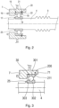
Fig. 2 ] Lafigure 2 illustre un agrandissement d'une zone de montage d'un arbre principal sur un carter de l'unité d'entraînement, selon le premier mode de réalisation de l'invention ; - [
Fig. 3 ] Lafigure 3 illustre un agrandissement d'une zone de montage d'un arbre principal sur un carter de l'unité d'entraînement, selon un deuxième mode de réalisation de l'invention ; - [
Fig. 4 ] Lafigure 4 illustre un roulement d'une unité d'entraînement d'un véhicule, selon un troisième mode de réalisation de l'invention ; - [
Fig. 5 ] Lafigure 5 illustre une unité d'entraînement d'un véhicule, selon un quatrième mode de réalisation de l'invention. - [
Fig. 6 ] Lafigure 6 illustre une unité d'entraînement d'un véhicule, selon un cinquième mode de réalisation de l'invention. - Sur la
figure 1 est illustrée une unité d'entraînement 1 d'un véhicule destiné plus particulièrement, bien que de manière non exclusive, à un engin de déplacement personnel motorisé selon un premier mode de réalisation de l'invention. Cette unité d'entraînement 1 comporte une machine électrique 2, un carter 3, un arbre principal 4, un arbre intermédiaire 5 et un différentiel 11. Le différentiel 11 permet de répartir le couple entre deux demi-arbres de sortie (non représentés sur lafigure 1 ). Le carter 3 comporte une première coquille 6 et une deuxième coquille 7. La première coquille 6 et la deuxième coquille 7 sont reliées fixement l'une à l'autre de manière à délimiter un espace 8. La deuxième coquille 7 est reliée à la machine électrique 2 par un premier côté et est reliée à la première coquille 6 par un deuxième côté opposé au premier côté. La deuxième coquille 7 peut être une partie d'un couvercle protecteur de la machine électrique 2. - L'arbre principal 4 est entraîné directement par la machine électrique 2. Dans un exemple non illustré, la machine électrique 2 présente un arbre de rotor avec une première portion d'extrémité qui est montée autour d'une deuxième portion d'extrémité de l'arbre principal 4 (non illustré). Ou bien dans un autre exemple, l'arbre principal 4 présente une troisième portion d'extrémité qui est montée autour d'une quatrième portion d'extrémité de l'arbre de rotor (non illustré).
- L'arbre intermédiaire 5 est relié à l'arbre principal 4 par engrènement de l'arbre principal 4 et de l'arbre intermédiaire 5 l'un avec l'autre. Pour cela, l'arbre principal 4 comporte une première denture 9 et l'arbre intermédiaire 5 présente une deuxième denture 10. L'arbre principal 4 et l'arbre intermédiaire 5 coopèrent par engrènement de la première denture 9 et de la deuxième denture 10 l'une avec l'autre.
- L'arbre intermédiaire 5 est destiné à coopérer également avec le différentiel 11. Pour cela, l'arbre intermédiaire 5 présente une troisième denture 12 et le différentiel 11 présente une quatrième denture 13. L'arbre intermédiaire 5 et le différentiel 11 coopèrent l'un avec l'autre par engrènement de la troisième denture 12 et de la quatrième denture 13 l'une avec l'autre.
- La première denture 9 et la troisième denture 12 sont formées directement sur l'arbre principal 4 et sur l'arbre intermédiaire 5 respectivement. Tandis que la deuxième denture 10 et la quatrième denture 13 sont formées chacune par une roue dentée rapportée.
- Selon l'exemple de réalisation
figure 1 , l'arbre principal 4, l'arbre intermédiaire 5 et le différentiel 11 sont montés sur la deuxième coquille 7 par l'intermédiaire respectivement d'un premier roulement 15, d'un deuxième roulement 26 et d'un troisième roulement 27. - L'arbre principal 4, l'arbre intermédiaire 5 et le différentiel 11 sont également montés sur la première coquille 6 par l'intermédiaire respectivement d'un quatrième roulement 14, d'un cinquième roulement 28 et d'un sixième roulement 29.
- Le premier roulement 15 est destiné à être positionné directement au contact de l'arbre principal 4. Cependant, en variante non illustrée comme précédemment mentionné, lorsque l'arbre de rotor est monté sur l'arbre principal 4, le premier roulement 15 est monté indirectement sur l'arbre principal 4 par l'intermédiaire de l'arbre de rotor (non illustré).
- Le premier roulement 15 présente une bague externe 16, une bague interne 17 et des billes telles que 18 disposées entre la bague externe 16 et la bague interne 17,
figure 2 . La bague externe 16 est apte à être montée sur la deuxième coquille 7. La bague interne 17 est apte à être montée directement sur l'arbre principal 4 ou bien indirectement sur l'arbre principal 4 par l'intermédiaire de l'arbre de rotor (non illustré). - La bague externe 16 présente une première gorge périphérique 19 et la deuxième coquille 7 présente une deuxième gorge périphérique 20. La bague externe 16 et la deuxième coquille 7 sont positionnées l'une par rapport à l'autre de telle manière à ce que la première gorge périphérique 19 et la deuxième gorge périphérique 20 sont positionnées l'une en regard de l'autre pour former un logement 22 dans lequel est inséré un circlips 21.
- La bague interne 17 est montée sur l'arbre principal 4 tout en étant en appui axial contre une protubérance 25. Cette protubérance peut être comme illustré une excroissance de l'arbre principal 4 ou bien un anneau rapporté (non illustré) ou bien un autre circlips (non illustré).
- En variante
figure 3 , est illustré un deuxième mode de réalisation avec un premier roulement 30 présentant une bague externe 301, une bague interne 302 et des billes 303 disposées entre la bague externe 301 et la bague interne 302. La bague externe 301 est montée sur la deuxième coquille 7 tandis que la bague interne 302 est montée sur l'arbre principal 4. Une troisième gorge périphérique 200 est formée seulement par la deuxième coquille 7. Cette gorge périphérique 200 est apte à recevoir un circlips 211. Ainsi, la bague externe 161 est positionnée axialement en appui par un premier côté directement contre la deuxième coquille 7 et par un deuxième côté opposé au premier côté indirectement contre la deuxième coquille 7 par l'intermédiaire du circlips 211. Le circlips 211 est alors coincé à l'intérieur de la gorge périphérique 200 entre la bague externe 301 et une butée 71 formée par la deuxième coquille 7. - Dans une autre variante
figure 4 , est illustré un troisième mode de réalisation de l'invention avec un premier roulement 23 présentant une bague externe 231, une bague interne 232 et des billes 233 disposées entre la bague externe 231 et la bague interne 232. Une butée 212 est montée sur la deuxième coquille 7 et est formé par une vis équipée d'une tige 213 et d'une tête de vis 214. La tige 213 est vissée à la coquille 7 de telle manière que la tête de vis 214 est placée en appui contre la bague externe 231. - Des rondelles élastiques telles que 24 peuvent être disposées entre la deuxième coquille 7 et la bague externe 231 par un premier côté et entre la bague externe 231 et la tête de vis 214 par un deuxième côté.
- Le deuxième roulement 26 et le troisième roulement 27 peuvent être chacun de configuration identique à l'un des premiers roulements 15, 30 ou 23 tels que précédemment décrits.
- Le quatrième roulement 14 est un roulement à rouleaux. Un tel roulement permet de résister à de fortes charges radiales.
- Le cinquième roulement 28 et le sixième roulement 29 peuvent être chacun de configuration identique au quatrième roulement.
- La
figure 5 illustre une unité d'entraînement 100 d'un véhicule destiné plus particulièrement, bien que de manière non exclusive, à un engin de déplacement personnel motorisé selon un quatrième mode de réalisation de l'invention. Cette unité d'entraînement 100 se différentie de celle illustrée enfigure 1 en ce qu'elle présente un arbre principal 40 qui est supporté uniquement sur la deuxième coquille 7 par un roulement identique au premier roulement 15. Cette unité d'entraînement 100 se différentie également de celle illustrée enfigure 1 en ce que les sens des efforts générés par l'arbre principal 4 est inversé. - Dans le premier mode de réalisation
figure 1 , la première denture 9, la deuxième denture 10, la troisième denture 12 et la quatrième denture 13 présentent chacune une forme hélicoïdale. La première denture 9 et la deuxième denture 10 sont réalisées de telle manière à ce que lorsque l'arbre principal 4, l'arbre intermédiaire 5 et le différentiel 11 sont engrenés les uns avec les autres selon un premier sens de rotation de l'arbre principal 4, un premier effort axial E1 est généré par l'arbre principal 4, un deuxième effort axial E2 est généré par l'arbre intermédiaire 5 et un troisième effort axial E3 est généré par le différentiel 11. Le premier effort axial E1 est dirigé depuis la deuxième coquille 7 vers la première coquille 6. Le deuxième effort axial E2 est dirigé depuis la première coquille 6 vers la deuxième coquille 7. Le troisième effort E3 est dirigé depuis la deuxième coquille 7 vers la première coquille 6. Selon ce premier sens de rotation de l'arbre principal 4, les différentes charges axiales résultants des différents efforts axiaux E1, E2 et E3 sont toutes retransmises directement ou indirectement par l'intermédiaire du circlips 21 à la deuxième coquille 7. - Dans l'exemple de la
figure 5 , des efforts axiaux E1', E2' et E3' équivalents aux efforts axiaux E1, E2 et E3 sont également représentés. On pourra noter que l'unité d'entraînement 100 est configurée de telle manière à ce que seul l'effort axial E1' est inversé par rapport à l'effort axial E1 tel qu'illustré enfigure 1 . Le sens de l'effort axial de E2' et de E3' est identique au sens de l'effort axial de E2 et de E3. De la même manière que pour l'exemple enfigure 1 , les différentes charges axiales résultants des différents efforts axiaux E1', E2' et E3' sont toutes retransmises directement ou indirectement par l'intermédiaire du circlips 21 à la deuxième coquille 7. - La
figure 6 illustre une unité d'entraînement d'un véhicule motorisé selon un cinquième mode de réalisation de l'invention. Cette unité d'entraînement se différentie de celle illustrée enfigure 1 en ce qu'elle présente des premiers moyens de retenu axial et des deuxièmes moyens de retenu axial communs et réalisés par une seule et même butée 212. - Dans cet exemple, les premiers moyens de retenu axial et les deuxièmes moyens de retenu axial sont décalés axialement et supportés par une seule et même butée 212. La butée 212 comprend une plaque commune 215 pourvue de deux orifices agencés pour le passage de l'arbre principal 4 et de l'arbre intermédiaire 5.
- La butée 212 est montée sur la deuxième coquille 7 et est formé par une vis équipée d'une tige 213 et d'une tête de vis 214. La tige est vissée à la deuxième coquille 7 de telle manière que la tête de vis 214 est placée en appui contre la plaque commune 215.
- Dans cet exemple, la machine électrique 2 présente un encombrement sensiblement cylindrique, notamment défini par son diamètre extérieur d, l'axe de rotation de l'arbre intermédiaire 5 est inscrit à l'intérieur du diamètre extérieur d de la machine électrique. Egalement, la machine électrique est en appui axial sur la deuxième coquille 7, par l'intermédiaire d'une surface d'appui 2a sensiblement circulaire ayant un diamètre extérieur d, l'axe de rotation de l'arbre intermédiaire 5 est inscrit à l'intérieur du diamètre extérieur d de la surface d'appui 2a.
Claims (14)
- Unité d'entraînement (1,100) d'un dispositif de mobilité, en particulier d'un véhicule, comprenant- une machine électrique (2),- un carter comprenant une première coquille (6) et une deuxième coquille (7), la deuxième coquille étant située entre la machine électrique et la première coquille,- un arbre principal (4,40) logé dans un espace (8) délimité par la première coquille et la deuxième coquille et étant apte à être mis en rotation par l'intermédiaire de la machine électrique,- l'arbre principal étant monté sur la deuxième coquille par l'intermédiaire d'un premier roulement (15,30,23),dans laquelle le premier roulement est monté sans jeu sur la deuxième coquille par l'intermédiaire de premiers moyens de retenu axial (21,211, 212).
- Unité d'entraînement selon la revendication 1 dans laquelle les premiers moyens de retenu axial sont localisés entre le premier roulement et la deuxième coquille.
- Unité d'entraînement selon la revendication 1 ou 2, dans laquelle les premiers moyens de retenu axial sont formés par un circlips (21,211) ou une vis (212).
- Unité d'entraînement selon la revendication 3, dans laquelle le premier roulement comporte une bague externe (16) apte à être montée sur la deuxième coquille et une bague interne (17) apte à être montée sur l'arbre principal, la bague externe comporte une première gorge périphérique (19) et la deuxième coquille comporte une deuxième gorge périphérique (20), la bague externe et la deuxième coquille étant positionnées l'une par rapport à l'autre de telle manière à ce que le circlips (21) est logé à l'intérieur de la première gorge et de la deuxième gorge.
- Unité d'entraînement selon la revendication 3, dans laquelle le premier roulement comporte une bague externe (301) apte à être montée sur la deuxième coquille et une bague interne (302) apte à être montée sur l'arbre principal, la deuxième coquille comportant une butée (71), le circlips (211) étant positionné en appui contre la butée et contre la bague externe.
- Unité d'entraînement selon la revendication 3, dans laquelle le premier roulement comporte une bague externe (231) apte à être montée sur la deuxième coquille et une bague interne (232) apte à être montée sur l'arbre principal, la vis étant formée par une tige (213) et par une tête de vis (214), la tige étant vissée dans la deuxième coquille de telle sorte à ce que la bague externe soit en appui contre la tête de vis.
- Unité d'entraînement selon la revendication 6, dans laquelle au moins une rondelle élastique (24) est montée entre la deuxième coquille et la bague externe et/ou entre la bague externe et la tête de vis.
- Unité d'entraînement selon l'une des revendications 1 à 7, dans laquelle elle comporte un deuxième roulement (14) monté sur la première coquille et disposé entre l'arbre principal et la première coquille.
- Unité d'entraînement selon la revendication 8, dans laquelle le deuxième roulement est à un roulement à rouleaux.
- Unité d'entraînement selon la revendication 9, dans laquelle le deuxième roulement (14) est monté avec jeu sur la première coquille.
- Unité d'entraînement selon l'une des revendications 1 à 10, dans laquelle elle comporte un arbre intermédiaire (5) qui coopère par engrènement avec l'arbre principal, l'arbre intermédiaire étant monté sur la deuxième coquille par l'intermédiaire d'un troisième roulement (26), le troisième roulement est monté sans jeu sur la deuxième coquille par l'intermédiaire de deuxièmes moyens de retenu axial (21,211,212).
- Unité d'entraînement selon la revendication 11, dans laquelle l'arbre intermédiaire est monté sur la première coquille par l'intermédiaire d'un cinquième roulement (28), le cinquième roulement étant un roulement à rouleaux.
- Unité d'entraînement selon la revendication 11 ou la revendication 12, dans laquelle l'arbre intermédiaire est positionné sur un même encombrement radial que celui de la machine électrique.
- Unité d'entraînement selon la revendication 12 ou 13, dans laquelle elle comporte un différentiel (11) qui coopère par engrènement avec l'arbre intermédiaire, le différentiel étant monté sur la deuxième coquille par l'intermédiaire d'un quatrième roulement (27), le quatrième roulement étant monté sans jeu sur la deuxième coquille par l'intermédiaire de troisièmes moyens de retenu axial (21,211,212).
Applications Claiming Priority (1)
| Application Number | Priority Date | Filing Date | Title |
|---|---|---|---|
| FR2306918A FR3150664A1 (fr) | 2023-06-29 | 2023-06-29 | Unité d’entrainement d’un dispositif de mobilité |
Publications (1)
| Publication Number | Publication Date |
|---|---|
| EP4484796A1 true EP4484796A1 (fr) | 2025-01-01 |
Family
ID=88413264
Family Applications (1)
| Application Number | Title | Priority Date | Filing Date |
|---|---|---|---|
| EP24181703.0A Pending EP4484796A1 (fr) | 2023-06-29 | 2024-06-12 | Unité d entrainement d'un dispositif de mobilité, en particulier d'un véhicule |
Country Status (4)
| Country | Link |
|---|---|
| US (1) | US20250007353A1 (fr) |
| EP (1) | EP4484796A1 (fr) |
| CN (1) | CN119217945A (fr) |
| FR (1) | FR3150664A1 (fr) |
Citations (6)
| Publication number | Priority date | Publication date | Assignee | Title |
|---|---|---|---|---|
| JPS60189616U (ja) * | 1984-05-25 | 1985-12-16 | 自動車電機工業株式会社 | ベアリングの取付構造 |
| US4821602A (en) * | 1986-11-04 | 1989-04-18 | Toyota Jidosha Kabushiki Kaisha | Support structure of differential gear unit |
| US20070099745A1 (en) * | 2003-07-02 | 2007-05-03 | Fox Gerald P | Transmission containing helical gearing and bearing arrangement therefor |
| CN104343827A (zh) * | 2013-07-31 | 2015-02-11 | 奥迪股份公司 | 用于把轴承的轴承外圈轴向固定在孔的轴承座中的内卡环和配置结构以及用于把轴承安装在孔中的方法 |
| WO2017145812A1 (fr) * | 2016-02-25 | 2017-08-31 | Ntn株式会社 | Actionneur linéaire électrique et dispositif de freinage électrique |
| WO2021217114A1 (fr) * | 2020-04-24 | 2021-10-28 | Linamar Corporation | Boulon traversant un arbre intermédiaire d'une boîte de vitesses à axe parallèle |
-
2023
- 2023-06-29 FR FR2306918A patent/FR3150664A1/fr active Pending
-
2024
- 2024-06-12 EP EP24181703.0A patent/EP4484796A1/fr active Pending
- 2024-06-21 CN CN202410806808.2A patent/CN119217945A/zh active Pending
- 2024-06-25 US US18/752,874 patent/US20250007353A1/en active Pending
Patent Citations (6)
| Publication number | Priority date | Publication date | Assignee | Title |
|---|---|---|---|---|
| JPS60189616U (ja) * | 1984-05-25 | 1985-12-16 | 自動車電機工業株式会社 | ベアリングの取付構造 |
| US4821602A (en) * | 1986-11-04 | 1989-04-18 | Toyota Jidosha Kabushiki Kaisha | Support structure of differential gear unit |
| US20070099745A1 (en) * | 2003-07-02 | 2007-05-03 | Fox Gerald P | Transmission containing helical gearing and bearing arrangement therefor |
| CN104343827A (zh) * | 2013-07-31 | 2015-02-11 | 奥迪股份公司 | 用于把轴承的轴承外圈轴向固定在孔的轴承座中的内卡环和配置结构以及用于把轴承安装在孔中的方法 |
| WO2017145812A1 (fr) * | 2016-02-25 | 2017-08-31 | Ntn株式会社 | Actionneur linéaire électrique et dispositif de freinage électrique |
| WO2021217114A1 (fr) * | 2020-04-24 | 2021-10-28 | Linamar Corporation | Boulon traversant un arbre intermédiaire d'une boîte de vitesses à axe parallèle |
Also Published As
| Publication number | Publication date |
|---|---|
| FR3150664A1 (fr) | 2025-01-03 |
| US20250007353A1 (en) | 2025-01-02 |
| CN119217945A (zh) | 2024-12-31 |
Similar Documents
| Publication | Publication Date | Title |
|---|---|---|
| EP0415820B1 (fr) | Mécanisme réducteur pour articulation sans jeu utilisable notamment pour le réglage de diverses parties d'un siège de véhicule automobile | |
| FR3109481A1 (fr) | Motoréducteur compact | |
| FR2897826A1 (fr) | Direction pour un vehicule automobile | |
| FR2549432A1 (fr) | Ensemble de direction assistee de vehicule | |
| FR2957628A1 (fr) | Reducteur et actionneur electrique comprenant un tel reducteur | |
| EP4247657A1 (fr) | Dispositif d'entraînement électrique d'un essieu d'un vehicule | |
| EP1436526B1 (fr) | Couronne de reducteur du type a train epicycloidal notamment pour demarreur de vehicule automobile | |
| EP1436525B1 (fr) | Reducteur a train epicycloidal notamment pour demarreur de vehicule automobile et demmarreur equipe d'un tel reducteur | |
| FR2797671A1 (fr) | Engrenage differentiel bloquant | |
| EP4484796A1 (fr) | Unité d entrainement d'un dispositif de mobilité, en particulier d'un véhicule | |
| FR2837773A1 (fr) | Appareil de direction du vehicule | |
| FR2771153A1 (fr) | Reducteur epicycloidal ou cycloidal et articulation de robot equipee d'un tel reducteur | |
| FR2829813A1 (fr) | Reducteur a train epicycloidal notamment pour demarreur de vehicule automobile et demarreur equipe d'un tel reducteur | |
| WO2023099774A1 (fr) | Ensemble de propulsion, notamment pour véhicule automobile | |
| FR2667374A1 (fr) | Dispositif de transmission d'un couple d'entrainement d'une roue motrice de vehicule automobile avec un roulement et un reducteur de vitesse integres a la roue. | |
| FR2751803A1 (fr) | Demarreur de vehicule automobile a reducteur comportant un dispositif amortisseur | |
| EP2380260A1 (fr) | Dispositif de production de couple, notamment dispositif d'orientation | |
| FR2727655A1 (fr) | Groupe moto-propulseur electrique ou hydraulique pour vehicule automobile | |
| WO2025114386A1 (fr) | Dispositif de transmission de puissance entre des arbres d'entree et de sortie coaxiaux | |
| FR2922380A3 (fr) | Dispositif reducteur de vitesse comprenant un moteur accouple a un reducteur planetaire | |
| FR3155152A1 (fr) | Actionneur pour un bras robotisé à configuration améliorée | |
| FR3071889B1 (fr) | Systeme d'embrayage comportant un plateau de reaction supporte par un organe d'entree | |
| FR3144242A1 (fr) | Système de transmission de couple avec module d’adaptation du couple | |
| WO2023111261A1 (fr) | Système de transmission comportant un dispositif d'entraînement différentiel | |
| EP0546918A1 (fr) | Roulement préassemblé à éléments codeur et capteur additionnels |
Legal Events
| Date | Code | Title | Description |
|---|---|---|---|
| PUAI | Public reference made under article 153(3) epc to a published international application that has entered the european phase |
Free format text: ORIGINAL CODE: 0009012 |
|
| STAA | Information on the status of an ep patent application or granted ep patent |
Free format text: STATUS: EXAMINATION IS IN PROGRESS |
|
| 17P | Request for examination filed |
Effective date: 20240612 |
|
| AK | Designated contracting states |
Kind code of ref document: A1 Designated state(s): AL AT BE BG CH CY CZ DE DK EE ES FI FR GB GR HR HU IE IS IT LI LT LU LV MC ME MK MT NL NO PL PT RO RS SE SI SK SM TR |