EP4484757A1 - Turbomachine - Google Patents
Turbomachine Download PDFInfo
- Publication number
- EP4484757A1 EP4484757A1 EP23779073.8A EP23779073A EP4484757A1 EP 4484757 A1 EP4484757 A1 EP 4484757A1 EP 23779073 A EP23779073 A EP 23779073A EP 4484757 A1 EP4484757 A1 EP 4484757A1
- Authority
- EP
- European Patent Office
- Prior art keywords
- impeller
- fluid
- seal portion
- seal
- turbomachine
- Prior art date
- Legal status (The legal status is an assumption and is not a legal conclusion. Google has not performed a legal analysis and makes no representation as to the accuracy of the status listed.)
- Withdrawn
Links
Images



Classifications
-
- F—MECHANICAL ENGINEERING; LIGHTING; HEATING; WEAPONS; BLASTING
- F16—ENGINEERING ELEMENTS AND UNITS; GENERAL MEASURES FOR PRODUCING AND MAINTAINING EFFECTIVE FUNCTIONING OF MACHINES OR INSTALLATIONS; THERMAL INSULATION IN GENERAL
- F16J—PISTONS; CYLINDERS; SEALINGS
- F16J15/00—Sealings
- F16J15/44—Free-space packings
- F16J15/447—Labyrinth packings
-
- F—MECHANICAL ENGINEERING; LIGHTING; HEATING; WEAPONS; BLASTING
- F04—POSITIVE - DISPLACEMENT MACHINES FOR LIQUIDS; PUMPS FOR LIQUIDS OR ELASTIC FLUIDS
- F04D—NON-POSITIVE-DISPLACEMENT PUMPS
- F04D17/00—Radial-flow pumps, e.g. centrifugal pumps; Helico-centrifugal pumps
- F04D17/08—Centrifugal pumps
- F04D17/10—Centrifugal pumps for compressing or evacuating
-
- F—MECHANICAL ENGINEERING; LIGHTING; HEATING; WEAPONS; BLASTING
- F04—POSITIVE - DISPLACEMENT MACHINES FOR LIQUIDS; PUMPS FOR LIQUIDS OR ELASTIC FLUIDS
- F04D—NON-POSITIVE-DISPLACEMENT PUMPS
- F04D29/00—Details, component parts, or accessories
- F04D29/05—Shafts or bearings, or assemblies thereof, specially adapted for elastic fluid pumps
- F04D29/051—Axial thrust balancing
-
- F—MECHANICAL ENGINEERING; LIGHTING; HEATING; WEAPONS; BLASTING
- F04—POSITIVE - DISPLACEMENT MACHINES FOR LIQUIDS; PUMPS FOR LIQUIDS OR ELASTIC FLUIDS
- F04D—NON-POSITIVE-DISPLACEMENT PUMPS
- F04D29/00—Details, component parts, or accessories
- F04D29/05—Shafts or bearings, or assemblies thereof, specially adapted for elastic fluid pumps
- F04D29/053—Shafts
-
- F—MECHANICAL ENGINEERING; LIGHTING; HEATING; WEAPONS; BLASTING
- F04—POSITIVE - DISPLACEMENT MACHINES FOR LIQUIDS; PUMPS FOR LIQUIDS OR ELASTIC FLUIDS
- F04D—NON-POSITIVE-DISPLACEMENT PUMPS
- F04D29/00—Details, component parts, or accessories
- F04D29/05—Shafts or bearings, or assemblies thereof, specially adapted for elastic fluid pumps
- F04D29/056—Bearings
-
- F—MECHANICAL ENGINEERING; LIGHTING; HEATING; WEAPONS; BLASTING
- F04—POSITIVE - DISPLACEMENT MACHINES FOR LIQUIDS; PUMPS FOR LIQUIDS OR ELASTIC FLUIDS
- F04D—NON-POSITIVE-DISPLACEMENT PUMPS
- F04D29/00—Details, component parts, or accessories
- F04D29/08—Sealings
- F04D29/10—Shaft sealings
- F04D29/102—Shaft sealings especially adapted for elastic fluid pumps
-
- F—MECHANICAL ENGINEERING; LIGHTING; HEATING; WEAPONS; BLASTING
- F04—POSITIVE - DISPLACEMENT MACHINES FOR LIQUIDS; PUMPS FOR LIQUIDS OR ELASTIC FLUIDS
- F04D—NON-POSITIVE-DISPLACEMENT PUMPS
- F04D29/00—Details, component parts, or accessories
- F04D29/40—Casings; Connections of working fluid
- F04D29/42—Casings; Connections of working fluid for radial or helico-centrifugal pumps
- F04D29/4206—Casings; Connections of working fluid for radial or helico-centrifugal pumps especially adapted for elastic fluid pumps
- F04D29/4226—Fan casings
Definitions
- the present disclosure relates to a turbomachine.
- thrust force in an axial direction may be generated on an impeller. If the thrust force is great, a thrust bearing is inevitably increased in size. For this reason, various techniques have been disclosed in order to reduce the thrust force.
- a seal cylindrical portion having the same diameter as that of an airtight seal mechanism of a shroud-type impeller is integrally provided on a rotary shaft on an air outlet side of the shroud-type impeller.
- the airtight seal mechanism is provided between the outer periphery of the seal cylindrical portion and a housing. Pressure on the air outlet side acts on the entire surface of the seal cylindrical portion on the shroud-type impeller side.
- a space is formed on the motor side with respect to the seal cylindrical portion in the housing. Pressure on the air inlet side of the shroud-type impeller is introduced into the space through a communication passage formed in the housing. The pressure on the air inlet side acts on the entire surface of the seal cylindrical portion on the motor side.
- Patent Document 1 Japanese Unexamined Patent Publication No. H11-218091
- the compression device according to Patent Document 1 has a complicated structure because it is necessary to provide two or more airtight seal mechanisms for one shroud-type impeller and to provide the space and the communication passage in the housing.
- a first aspect of the present disclosure is directed to a turbomachine (1).
- the turbomachine (1) includes a rotary shaft (10), an impeller (20) provided on the rotary shaft (10), a casing (30) housing the rotary shaft (10), a prime mover (40) spaced apart from the impeller (20) in the axial direction of the rotary shaft (10) and rotating the rotary shaft (10), and a seal portion (70) sealing between the impeller (20) side and the prime mover (40) side.
- the impeller (20) has an impeller suction portion (21) into which fluid (W) is sucked, and an impeller discharge portion (22) from which the fluid (W) is discharged.
- the seal portion (70) has a rotary seal portion (71) provided on the rotary shaft (10), and a fixed seal portion (72) provided on the casing (30).
- the rotary seal portion (71) and the fixed seal portion (72) are spaced apart from each other in the radial direction of the rotary shaft (10), and extends in the axial direction.
- the rotary seal portion (71) and the fixed seal portion (72) form a leakage flow path (73) through which the fluid (W) discharged from the impeller discharge portion (22) leaks from the impeller (20) side to the prime mover (40) side.
- the maximum seal diameter (S1) of the leakage flow path (73) is greater than the inlet diameter (D1) of the impeller suction portion (21).
- thrust force (F) acting on the impeller (20) can be made close to zero simply by adjusting the maximum seal diameter (S1) of the leakage flow path (73) within the range greater than the inlet diameter (D1) of the impeller suction portion (21).
- the turbomachine (1) capable of reducing the thrust force (F) with a simple configuration can be provided.
- a second aspect of the present disclosure is an embodiment of the first aspect.
- a pressure (P3) on the prime mover (40) side is lower than the pressure (P2) of the fluid (W) discharged from the impeller discharge portion (22).
- the thrust force (F) acting on the impeller (20) can be more reliably made close to zero.
- a third aspect of the present disclosure is an embodiment of the first or second aspect.
- the seal circumferential speed (V) of the rotary seal portion (71) is 0.8 times or more the sound speed (A) of the fluid (W).
- the third aspect is advantageous in reducing leakage of the fluid (W) from the impeller (20) side to the prime mover (40) side through the leakage flow path (73).
- a fourth aspect of the present disclosure is an embodiment of the third aspect.
- the seal circumferential speed (V) is 0.8 times or more the sound speed (A1) of the fluid (W) on the impeller (20) side.
- the fourth aspect is more advantageous in reducing the leakage of the fluid (W) through the leakage flow path (73).
- a fifth aspect of the present disclosure is an embodiment of the third or fourth aspect.
- the seal circumferential speed (V) is 0.8 times or more the sound speed (A2) of the fluid (W) on the prime mover (40) side.
- the fifth aspect is more advantageous in reducing the leakage of the fluid (W) through the leakage flow path (73).
- a sixth aspect of the present disclosure is an embodiment of any one of the first to fifth aspects.
- the rotary shaft (10) is supported by a non-contact bearing (50, 60).
- the rotary shaft (10) can be supported in a non-contact manner, and therefore, the rotary shaft (10) can be rotated at a high speed and a bearing loss can be reduced.
- a seventh aspect of the present disclosure is an embodiment of any one of the first to sixth aspects.
- the leakage flow path (73) is formed in a step shape or a corrugated shape.
- the pressure loss of the fluid (W) in the leakage flow path (73) increases, and therefore, the leakage of the fluid (W) through the leakage flow path (73) can be reduced.
- An eighth aspect of the present disclosure is an embodiment of any one of the first to seventh aspects.
- the turbomachine (1) of the eighth aspect is a turbo compressor (1).
- the fluid (W) can be compressed and pressurized.
- a ninth aspect of the present disclosure is an embodiment of the eighth aspect.
- the fluid (W) is natural refrigerant including one of HFC refrigerant, HFO refrigerant, or HC refrigerant, or a refrigerant mixture including at least two of the HFC refrigerant, the HFO refrigerant, and the HC refrigerant.
- the turbo compressor (1) can be applied to a refrigeration apparatus.
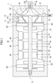
- FIG. 1 illustrates a longitudinal sectional view of a turbo compressor (1) as a turbomachine (1) according to a first embodiment of the present disclosure.
- the turbo compressor (1) is a centrifugal turbo compressor.
- the turbo compressor (1) compresses and pressurizes fluid (W).
- the fluid (W) is preferably natural refrigerant including one of HFC refrigerant, HFO refrigerant, or HC refrigerant, or a refrigerant mixture including at least two of HFC refrigerant, HFO refrigerant, and HC refrigerant.
- the HFC refrigerant includes R32, R125, R134a, R143a, and R245fa, for example.
- the HFO refrigerant includes R1234yf, R1234ze, R1233zd, R1123, and R1132(E), for example.
- the HC refrigerant includes R744, R717, R290, R600a, and R1270, for example.
- a turbo compressor (1) is applied to a refrigeration apparatus such as an air conditioner.
- the refrigeration apparatus includes a refrigerant circuit in which refrigerant circulates.
- the turbo compressor (1) compresses the refrigerant in the refrigerant circuit.
- the refrigerant circulates in the refrigerant circuit, thereby performing a vapor compression refrigeration cycle.
- the turbo compressor (1) includes a shaft (10) as a rotary shaft (10), an impeller (20), a casing (30), a motor (40) as a prime mover (40), a radial magnetic bearing (50) as a non-contact bearing (50), a thrust magnetic bearing (60) as a non-contact bearing (60), and a seal portion (70).
- a term “axial direction” refers to a direction in which the axis (O) of the shaft (10) extends.
- a term “one side” refers to the right side in FIG. 1 .
- a term “other side” refers to the left side in FIG. 1 .
- a term "radial direction” refers to a direction perpendicular to the axial direction.
- An “outer peripheral side” refers to a side farther from the axis (O) of the shaft (10) in the radial direction.
- An “inner peripheral side” refers to a side closer to the axis (O) of the shaft (10) in the radial direction.
- a “circumferential direction” refers to the direction of rotation of the shaft (10) about the axis (O).
- the impeller (20) is provided at one end portion of the shaft (10).
- the impeller (20) rotates integrally with the shaft (10).
- the impeller (20) has a substantially conical outer shape which is raised toward the one side in the axial direction.
- the impeller (20) is a closed impeller.
- the impeller (20) has a shroud (side plate) and a plurality of blades.
- the impeller (20) has an impeller suction portion (21) and an impeller discharge portion (22).
- the impeller suction portion (21) opens on the one side of the impeller (20).
- the impeller suction portion (21) faces the one side.
- the impeller suction portion (21) has a substantially circular shape as viewed in the axial direction.
- the fluid (W) is sucked into the impeller suction portion (21).
- the impeller suction portion (21) is a fluid (W) inlet of the impeller (20).
- the impeller suction portion (21) has an inlet diameter (D1) as a diameter centered on the axis (O).
- the inlet diameter (D1) may be an outer diameter including a thick portion or an inner diameter not including the thick portion.
- the impeller discharge portion (22) opens on the outer peripheral side of the impeller (20).
- the impeller discharge portion (22) faces the outer peripheral side.
- the impeller discharge portion (22) is formed by a clearance surrounded by the shroud and the plurality of blades of the impeller (20).
- the fluid (W) is discharged from the impeller discharge portion (22).
- the impeller discharge portion (22) is a fluid (W) outlet of the impeller (20).
- the impeller discharge portion (22) has an outlet diameter (D2) as a diameter centered on the axis (O).
- the outlet diameter (D2) of the impeller discharge portion (22) is greater than the inlet diameter (D1) of the impeller suction portion (21).
- the casing (30) houses the shaft (10).
- the casing (30) further houses the impeller (20), the motor (40), the radial magnetic bearing (50), the thrust magnetic bearing (60), and the seal portion (70).
- the casing (30) is formed in a cylindrical shape with both ends closed.
- the axis of the casing (30) extends horizontally coaxially with the axis (O) of the shaft (10).
- An internal space of the casing (30) is partitioned in the axial direction by a partition wall (31).
- An impeller space (32) is formed in the casing (30) on the one side with respect to the partition wall (31).
- a motor space (33) is formed in the casing (30) on the other side with respect to the partition wall (31).
- One end portion of the shaft (10) and the impeller (20) are housed in the impeller space (32).
- a portion of the shaft (10) other than the one end portion, the motor (40), the radial magnetic bearing (50), and the thrust magnetic bearing (60) are housed in the motor space (33).
- the seal portion (70) is housed on the inner peripheral side of the partition wall (31).
- a suction pipe (34) and a discharge pipe (35) are connected to the impeller space (32).
- the impeller space (32) has an outer peripheral portion forming a compression space (36).
- the suction pipe (34) guides the fluid (W) from the outside to the impeller space (32).
- the discharge pipe (35) discharges, to the outside, the fluid (W) compressed to a high pressure in the impeller space (32).
- the motor (40) is housed in the motor space (33).
- the motor (40) is spaced apart from the impeller (20) housed in the impeller space (32) in the axial direction of the shaft (10).
- the motor (40) has a rotor (41) and a stator (42).
- the rotor (41) is fixed to the shaft (10) in the motor space (33) so as to rotate integrally with the shaft (10).
- the stator (42) is fixed to the inner peripheral surface of the casing (30) in the motor space (33).
- the outer peripheral surface of the rotor (41) and the inner peripheral surface of the stator (42) face each other in the radial direction with a predetermined gap therebetween.
- the motor (40) is, for example, a permanent magnet synchronous motor.
- the motor (40) rotates the shaft (10).
- the radial magnetic bearing (50) applies, as an electromagnet, electromagnetic force to the shaft (10) in the radial direction, thereby supporting the shaft (10) in the radial direction such that the radial magnetic bearing (50) supports the shaft (10) with respect to the casing (30) in a non-contact manner.
- the two radial magnetic bearings (50) are arranged side by side in the axial direction of the shaft (10).
- the two radial magnetic bearings (50) are spaced apart from each other with the motor (40) interposed therebetween.
- the radial magnetic bearing (50) has a rotor (51) and a stator (52).
- the rotor (51) is fixed to the shaft (10) in the motor space (33) so as to rotate integrally with the shaft (10).
- the stator (52) is fixed to the inner peripheral surface of the casing (30) in the motor space (33).
- the outer peripheral surface of the rotor (51) and the inner peripheral surface of the stator (52) face each other in the radial direction with a predetermined gap therebetween.
- the thrust magnetic bearing (60) applies, as an electromagnet, electromagnetic force to the shaft (10) in the axia1 direction, thereby supporting the shaft (10) in the axial direction such that the thrust magnetic bearing (60) supports the shaft (10) with respect to the casing (30) in a non-contact manner.
- the two thrust magnetic bearings (60) are arranged side by side in the axial direction of the shaft (10).
- the two thrust magnetic bearings (60) are spaced apart from each other with the motor (40) interposed therebetween.
- the thrust magnetic bearing (60) includes a rotor (61) and a stator (62).
- the rotor (61) is fixed to the shaft (10) in the motor space (33) so as to rotate integrally with the shaft (10).
- the stator (62) is fixed to the inner peripheral surface of the casing (30) in the motor space (33).
- the rotor (61) and the stator (62) face each other in the axial direction with a predetermined gap therebetween.
- the stator (62) is arranged outside the rotor (61) in the axial direction.
- the stator (62) In the thrust magnetic bearing (60) on the one side, the stator (62) is located on the one side of the rotor (61). The thrust magnetic bearing (60) on the one side applies electromagnetic force to the one side of the shaft (10). In the thrust magnetic bearing (60) on the other side, the stator (62) is located on the other side of the rotor (61). The thrust magnetic bearing (60) on the other side applies electromagnetic force to the other side of the shaft (10).
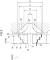
- FIG. 2 is an enlarged view of a portion II in FIG. 1 , which illustrates the seal portion (70) in closeup.
- the seal portion (70) is disposed on the inner peripheral side of the partition wall (31) in the casing (30).
- the one side with respect to the partition wall (31) is referred to as an "impeller (20) side.”
- the other side with respect to the partition wall (31) is referred to as a "motor (40) side.”
- the seal portion (70) seals between the impeller space (32) on the impeller side with respect to the partition wall (31) and the motor space (33) on the motor (40) side (prime mover (40) side) with respect to the partition wall (31).
- the seal portion (70) has a rotary seal portion (71) and a fixed seal portion (72).
- the rotary seal portion (71) is provided on the shaft (10) on the inner peripheral side of the partition wall (31).
- the rotary seal portion (71) rotates integrally with the shaft (10).
- the fixed seal portion (72) is provided on the casing (30). Specifically, the fixed seal portion (72) is fixed to the inner peripheral surface of the partition wall (31) in the casing (30).
- the rotary seal portion (71) is formed in a substantially cylindrical shape.
- the rotary seal portion (71) extends in the axial direction of the shaft (10).
- the fixed seal portion (72) is formed in a substantially cylindrical shape.
- the fixed seal portion (72) extends in the axial direction of the shaft (10).
- the rotary seal portion (71) and the fixed seal portion (72) are spaced apart from each other in the radial direction of the shaft (10) with a predetermined gap therebetween.
- the rotary seal portion (71) and the fixed seal portion (72) form a leakage flow path (73).
- the leakage flow path (73) is formed in a clearance between the rotary seal portion (71) and the fixed seal portion (72) in the radial direction.
- the fluid (W) discharged from the impeller discharge portion (22) of the impeller (20) leaks from the impeller space (32) on the impeller side to the motor space (33) on the motor (40) side (prime mover (40) side) through the leakage flow path (73).
- the leakage flow path (73) is formed in a step shape. Specifically, the outer peripheral surface of the rotary seal portion (71) is provided with a step portion (74). The inner peripheral surface of the fixed seal portion (72) is provided with a step portion (74). The step portion (74) on the rotary seal portion (71) side and the step portion (74) on the fixed seal portion (72) side correspond to each other.
- the diameter [mm] (diameter centered on the axis (O)) of the leakage flow path (73) is smaller on the motor (40) side than on the impeller (20) side due to the presence of the step portion (74).
- the diameter of the leakage flow path (73) is substantially equal to the outer diameter of the rotary seal portion (71) and the inner diameter of the fixed seal portion (72).
- the leakage flow path (73) has the maximum seal diameter (S 1) [mm] at an end portion (one end portion) on the impeller (20) side, and has the minimum seal diameter (S2) [mm] at an end portion (other end portion) on the motor (40) side.
- the maximum seal diameter (S 1) of the leakage flow path (73) is the inlet diameter (D1) of the impeller suction portion (21) or more. Specifically, the maximum seal diameter (S 1) is greater than the inlet diameter (D 1).
- the maximum seal diameter (S 1) of the leakage flow path (73) is the outlet diameter (D2) of the impeller discharge portion (22) or less. Specifically, the maximum seal diameter (S 1) is smaller than the outlet diameter (D2).
- the minimum seal diameter (S2) of the leakage flow path (73) is the inlet diameter (D1) of the impeller suction portion (21) or more. Specifically, the minimum seal diameter (S2) is greater than the inlet diameter (D 1).
- the minimum seal diameter (S2) of the leakage flow path (73) is the outlet diameter (D2) of the impeller discharge portion (22) or less. Specifically, the minimum seal diameter (S2) is smaller than the outlet diameter (D2).
- FIG. 3 schematically illustrates thrust force (F) acting on the impeller (20).
- the shape of the rotary seal portion (71) is simplified.
- a discharge pressure (P2) which is the pressure of the fluid (W) discharged from the impeller discharge portion (22) is higher than a suction pressure (P1) which is the pressure of the fluid (W) sucked into the impeller suction portion (21) (Discharge Pressure (P2) > Suction Pressure (P1)).
- a motor space pressure (P3) which is a pressure in the motor space (33) on the motor (40) side (prime mover (40) side) is lower than the discharge pressure (P2) which is the pressure of the fluid (W) discharged from the impeller discharge portion (22) (Motor Space Pressure (P3) ⁇ Discharge Pressure (P2)).
- the motor space pressure (P3) is substantially equal to the suction pressure (P1) (Motor Space Pressure (P3) ⁇ Suction Pressure (P1)).
- the motor space pressure (P3) is adjusted by controlling the pressure of the refrigerant for cooling the motor (40).
- a pressure (P(x)) between the impeller suction portion (21) and the impeller discharge portion (22) is the function of a radial distance (x) from the axis (O).
- the pressure P(x) is the suction pressure (P1) or more and the discharge pressure (P2) or less (Suction Pressure (P1) ⁇ Pressure P(x) ⁇ Discharge Pressure (P2)).
- a first thrust force (F1) acting on the motor (40) side (other side) is obtained by Expression 1 below.
- F1 P1 ⁇ ⁇ 4 D1 2 + ⁇ D 1 2 D2 2 2 ⁇ xP x dx
- F2 P2 ⁇ ⁇ 4 D2 2 ⁇ S1 2 + P3 ⁇ ⁇ 4 S1 2 ⁇ P2 ⁇ ⁇ 4 D2 2 ⁇ S1 2 + P1 ⁇ ⁇ 4 S1 2
- the thrust force (F) can be theoretically reduced to zero by setting the maximum seal diameter (S 1) within the range of Inlet Diameter (D1) ⁇ Maximum Seal Diameter (S1) ⁇ Outlet Diameter (D2).
- the seal circumferential speed (V) [m/s] of the rotary seal portion (71) is obtained by Expression 9 below using the maximum seal diameter (S 1) [mm] of the leakage flow path (73) and the number of rotations (C) [rpm] of the shaft (10).
- the number of rotations (C) of the shaft (10) is substantially equal to the number of rotations (C) of the motor (40).
- the number of rotations (C) [rpm] includes the maximum number of rotations, the rated number of rotations, and the number of rotations in normal operation, for example.
- V ⁇ ⁇ S1 ⁇ C 60 ⁇ 1000
- a Mach number (V/A) [-] is obtained by dividing the seal circumferential speed (V) of the rotary seal portion (71) by the sound speed (A) [m/s] of the fluid (W).
- the sound speed (A) is obtained by Expression 10 below using an average molecular weight (M), a specific heat ratio (k), a gas constant (R), and the temperature (T) of the fluid (W).
- M average molecular weight
- k specific heat ratio
- R gas constant
- T temperature of the fluid
- the gas constant (R) is basically invariant.
- W type of fluid
- M average molecular weight
- k specific heat ratio
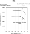
- FIGS. 4 and 5 illustrate a relationship between the Mach number (V/A) [-] of the rotary seal portion (71) and the leakage flow rate [m/s] of the fluid (W) in the leakage flow path (73).
- FIG. 4 illustrates the relationship between the Mach number (V/A1) [-] of the rotary seal portion (71) and the leakage flow rate [m/s] of the fluid (W) in the leakage flow path (73) at the sound speed [A1] of the fluid (W) on the impeller (20) side (high-pressure side).
- V/A2 [-] of the rotary seal portion (71) illustrates the relationship between the Mach number (V/A2) [-] of the rotary seal portion (71) and the leakage flow rate [m/s] of the fluid (W) in the leakage flow path (73) at the sound speed [A2] of the fluid (W) on the motor (40) side.
- the leakage flow rate [m/s] starts decreasing when the Mach number (V/A1) [-] reaches 0.8 or more, further decreases when the Mach number (V/A1) [-] reaches 0.9 or more, and significantly decreases when the Mach number (V/A1) [-] reaches 1.0 or more.
- the leakage flow rate [m/s] starts decreasing when the Mach number (V/A2) [-] reaches 0.8 or more, further decreases when the Mach number (V/A2) [-] reaches 0.9 or more, and significantly decreases when the Mach number (V/A2) [-] reaches 1.0 or more.
- the temperature in the vicinity of the impeller suction portion (21) in the impeller space (32) is about 25 [°C] to 50 [°C]
- the temperature in the vicinity of the impeller discharge portion (22) in the impeller space (32) is about 35 [°C] to 90 [°C]
- the temperature in the motor space (33) is about 20 [°C] to 70 [°C].
- the seal differential pressure is 0.15 [MPa]
- the number of rotations (C) is changed between 50000 [rpm] and 110000 [rpm].
- the temperature in the vicinity of the impeller suction portion (21) in the impeller space (32) is about 25 [°C] to 55 [°C]
- the temperature in the vicinity of the impeller discharge portion (22) in the impeller space (32) is about 50 [°C] to 110 [°C]
- the temperature in the motor space (33) is about minus 10 [°C] to plus 70 [°C].
- the seal differential pressure is 0.35 [MPa]
- the number of rotations (C) is changed between 80000 [rpm] and 125000 [rpm].
- Mach Number (V/A1) Leakage Flow Rate [m/s] is 0.54:0.0001507, 0.92:0.0001476, 1.03:0.0001452, and 1.07:0.0001256.
- the relationship between the Mach number (V/A2) and the leakage flow rate [m/s] in the motor space (33) is as follows: Mach Number (V/A2) : Leakage Flow Rate [m/s] is 0.42:0.0001507, 0.81:0.0001476, 0.92:0.0001452, and 0.95:0.0001256.
- Mach Number (V/A1) Leakage Flow Rate [m/s] is 0.92:0.0002202, 0.96:0.0002169, 1.04:0.0002165, 1.11:0.0002028, and 1.14:0.0001952.
- Mach Number (V/A2) Leakage Flow Rate [m/s] is 0.78:0.0002202, 0.82:0.0002169, 0.88:0.0002165, 0.98:0.0002028, and 0.99:0.0001952.
- the seal circumferential speed (V) of the rotary seal portion (71) is 0.8 times or more the sound speed (A) of the fluid (W) (i.e., the Mach number (V/A) is 0.8 or more).
- the seal circumferential speed (V) of the rotary seal portion (71) is 0.8 times or more the sound speed (A1) of the fluid (W) on the impeller (20) side (high-pressure side) (i.e., the Mach number (V/A1) in the impeller space (32) is 0.8 or more).
- the seal circumferential speed (V) of the rotary seal portion (71) is 0.8 times or more the sound speed (A2) of the fluid (W) on the motor (40) side (prime mover (40) side: low-pressure side) (i.e., the Mach number (V/A2) in the motor space (33) is 0.8 or more).
- the thrust force (F) acting on the impeller (20) can be made close to zero simply by adjusting the maximum seal diameter (S1) of the leakage flow path (73) within the range greater than the inlet diameter (D1) of the impeller suction portion (21).
- the turbomachine (1) capable of reducing the thrust force (F) with a simple configuration can be provided.
- the thrust magnetic bearing (60) can be reduced in size by reduction in the thrust force (F). Further, a complicated mechanism for reducing the thrust force (F) is not required, and therefore, the configuration of the turbomachine (1) can be simplified and the axial length of the shaft (10) can be reduced. By reducing the axial length of the shaft (10), the eigenfrequency of the rotating body including the shaft (10) increases, and therefore, the shaft (10) can be rotated at a high speed.
- the seal circumferential speed (V) of the rotary seal portion (71) is 0.8 times or more the sound speed (A) of the fluid (W) (i.e., if the Mach number (V/A) is 0.8 or more)
- the seal circumferential speed (V) (Mach number (V/A)) reaches the transonic range, and the frictional resistance of the fluid (W) increases. This is advantageous in reducing the leakage of the fluid (W) from the impeller (20) side to the motor (40) side through the leakage flow path (73).
- the seal circumferential speed (V) of the rotary seal portion (71) is 0.8 times or more the sound speed (A1) of the fluid (W) on the impeller (20) side and 0.8 times or more the sound speed (A2) of the fluid (W) on the motor (40) side, which is more advantageous in reducing the leakage of the fluid (W) through the leakage flow path (73).
- the shaft (10) can be supported in a non-contact manner by the radial magnetic bearing (50) and the thrust magnetic bearing (60), the shaft (10) can be rotated at a high speed and a bearing loss can be reduced.
- the high-speed rotation of the shaft (10) is advantageous in increasing the seal circumferential speed (V) of the rotary seal portion (71).
- the step-like leakage flow path (73) increases the pressure loss of the fluid (W) in the leakage flow path (73), and therefore, the leakage of the fluid (W) through the leakage flow path (73) can be reduced.
- the turbomachine (1) is applied as the turbo compressor (1), and therefore, the fluid (W) can be compressed and pressurized.
- the fluid (W) is applied as the refrigerant, and therefore, the turbo compressor (1) can be applied to the refrigeration apparatus.
- FIG. 6 is a view according to a second embodiment, which corresponds to FIG. 2 , and illustrates the seal portion (70) in closeup.
- the leakage flow path (73) is not formed in the step shape.
- the diameter of the leakage flow path (73) is constant regardless of a position in the axial direction. In other words, the maximum seal diameter (S 1) of the leakage flow path (73) and the minimum seal diameter (S2) of the leakage flow path (73) are equal to each other.
- the leakage flow path (73) is formed in a labyrinth shape.
- the leakage flow path (73) is formed in a corrugated shape.
- the inner peripheral surface of the fixed seal portion (72) is provided with grooves (75) extending in the circumferential direction and arranged in the axial direction.
- the corrugated leakage flow path (73) increases the pressure loss of the fluid (W) in the leakage flow path (73), and therefore, the leakage of the fluid (W) through the leakage flow path (73) can be reduced.
- the impeller (20) may be an open impeller instead of the closed impeller. Even in a case where the impeller (20) is the open impeller, the thrust force (F) acting on the impeller (20) can be calculated by the expressions above.
- the minimum seal diameter (S2) of the leakage flow path (73) may be smaller than the inlet diameter (D1) of the impeller suction portion (21).
- the shaft (10) may be supported in a non-contact manner by an air bearing as the non-contact bearing (50, 60).
- an air bearing for example, a spiral groove bearing or a foil bearing may be applied.
- the shaft (10) may be supported by a sliding bearing or a rolling bearing.
- the turbomachine (1) may be applied as a pump (e.g., centrifugal pump) instead of the turbo compressor (1).
- liquid may be applied as the fluid (W).
- step shape (step portion (74)) of the leakage flow path (73) in the first embodiment and the corrugated shape (grooves (75)) of the leakage flow path (73) in the second embodiment may be combined with each other.
- the rotary seal portion (71) may be formed integrally with the shaft (10).
- the fixed seal portion (72) may be formed integrally with the casing (30).
- the axis (O) of the shaft (10) may extend in the vertical direction.
- the thrust force (F) but also gravitation needs to be considered as a load acting on the impeller (20) in the axial direction.
- the prime mover (40) is not limited to the motor (40), and for example, may be an engine.
Landscapes
- Engineering & Computer Science (AREA)
- General Engineering & Computer Science (AREA)
- Mechanical Engineering (AREA)
- Structures Of Non-Positive Displacement Pumps (AREA)
- Magnetic Bearings And Hydrostatic Bearings (AREA)
- Sealing Using Fluids, Sealing Without Contact, And Removal Of Oil (AREA)
Abstract
Description
- The present disclosure relates to a turbomachine.
- In a turbomachine such as a turbo compressor or a pump, thrust force in an axial direction may be generated on an impeller. If the thrust force is great, a thrust bearing is inevitably increased in size. For this reason, various techniques have been disclosed in order to reduce the thrust force.
- For example, in a compression device according to
Patent Document 1, a seal cylindrical portion having the same diameter as that of an airtight seal mechanism of a shroud-type impeller is integrally provided on a rotary shaft on an air outlet side of the shroud-type impeller. The airtight seal mechanism is provided between the outer periphery of the seal cylindrical portion and a housing. Pressure on the air outlet side acts on the entire surface of the seal cylindrical portion on the shroud-type impeller side. - A space is formed on the motor side with respect to the seal cylindrical portion in the housing. Pressure on the air inlet side of the shroud-type impeller is introduced into the space through a communication passage formed in the housing. The pressure on the air inlet side acts on the entire surface of the seal cylindrical portion on the motor side.
- Thus, the pressure on the air outlet side, which acts on the shroud-type impeller and the rotary shaft, is cancelled, and generation of the thrust force is reduced.
- Patent Document 1:
Japanese Unexamined Patent Publication No. H11-218091 - The compression device according to
Patent Document 1 has a complicated structure because it is necessary to provide two or more airtight seal mechanisms for one shroud-type impeller and to provide the space and the communication passage in the housing. - It is an object of the present disclosure to provide a turbomachine capable of reducing thrust force with a simple configuration.
- A first aspect of the present disclosure is directed to a turbomachine (1). The turbomachine (1) includes a rotary shaft (10), an impeller (20) provided on the rotary shaft (10), a casing (30) housing the rotary shaft (10), a prime mover (40) spaced apart from the impeller (20) in the axial direction of the rotary shaft (10) and rotating the rotary shaft (10), and a seal portion (70) sealing between the impeller (20) side and the prime mover (40) side. The impeller (20) has an impeller suction portion (21) into which fluid (W) is sucked, and an impeller discharge portion (22) from which the fluid (W) is discharged. The seal portion (70) has a rotary seal portion (71) provided on the rotary shaft (10), and a fixed seal portion (72) provided on the casing (30). The rotary seal portion (71) and the fixed seal portion (72) are spaced apart from each other in the radial direction of the rotary shaft (10), and extends in the axial direction. The rotary seal portion (71) and the fixed seal portion (72) form a leakage flow path (73) through which the fluid (W) discharged from the impeller discharge portion (22) leaks from the impeller (20) side to the prime mover (40) side. The maximum seal diameter (S1) of the leakage flow path (73) is greater than the inlet diameter (D1) of the impeller suction portion (21).
- In the first aspect, thrust force (F) acting on the impeller (20) can be made close to zero simply by adjusting the maximum seal diameter (S1) of the leakage flow path (73) within the range greater than the inlet diameter (D1) of the impeller suction portion (21). Thus, the turbomachine (1) capable of reducing the thrust force (F) with a simple configuration can be provided.
- A second aspect of the present disclosure is an embodiment of the first aspect. In the turbomachine (1) of the second aspect, a pressure (P3) on the prime mover (40) side is lower than the pressure (P2) of the fluid (W) discharged from the impeller discharge portion (22).
- In the second aspect, the thrust force (F) acting on the impeller (20) can be more reliably made close to zero.
- A third aspect of the present disclosure is an embodiment of the first or second aspect. In the turbomachine (1) of the third aspect, the seal circumferential speed (V) of the rotary seal portion (71) is 0.8 times or more the sound speed (A) of the fluid (W).
- The third aspect is advantageous in reducing leakage of the fluid (W) from the impeller (20) side to the prime mover (40) side through the leakage flow path (73).
- A fourth aspect of the present disclosure is an embodiment of the third aspect. In the turbomachine (1) of the fourth aspect, the seal circumferential speed (V) is 0.8 times or more the sound speed (A1) of the fluid (W) on the impeller (20) side.
- The fourth aspect is more advantageous in reducing the leakage of the fluid (W) through the leakage flow path (73).
- A fifth aspect of the present disclosure is an embodiment of the third or fourth aspect. In the turbomachine (1) of the fifth aspect, the seal circumferential speed (V) is 0.8 times or more the sound speed (A2) of the fluid (W) on the prime mover (40) side.
- The fifth aspect is more advantageous in reducing the leakage of the fluid (W) through the leakage flow path (73).
- A sixth aspect of the present disclosure is an embodiment of any one of the first to fifth aspects. In the turbomachine (1) of the sixth aspect, the rotary shaft (10) is supported by a non-contact bearing (50, 60).
- In the sixth aspect, the rotary shaft (10) can be supported in a non-contact manner, and therefore, the rotary shaft (10) can be rotated at a high speed and a bearing loss can be reduced.
- A seventh aspect of the present disclosure is an embodiment of any one of the first to sixth aspects. In the turbomachine (1) of the seventh aspect, the leakage flow path (73) is formed in a step shape or a corrugated shape.
- In the seventh aspect, the pressure loss of the fluid (W) in the leakage flow path (73) increases, and therefore, the leakage of the fluid (W) through the leakage flow path (73) can be reduced.
- An eighth aspect of the present disclosure is an embodiment of any one of the first to seventh aspects. The turbomachine (1) of the eighth aspect is a turbo compressor (1).
- In the eighth aspect, the fluid (W) can be compressed and pressurized.
- A ninth aspect of the present disclosure is an embodiment of the eighth aspect. In the turbomachine (1) of the ninth aspect, the fluid (W) is natural refrigerant including one of HFC refrigerant, HFO refrigerant, or HC refrigerant, or a refrigerant mixture including at least two of the HFC refrigerant, the HFO refrigerant, and the HC refrigerant.
- In the ninth aspect, the turbo compressor (1) can be applied to a refrigeration apparatus.
-
-
FIG. 1 illustrates a longitudinal sectional view of a turbo compressor (1) according to a first embodiment of the present disclosure. -
FIG. 2 is an enlarged view of a portion II inFIG. 1 , which illustrates a seal portion (70) in closeup. -
FIG. 3 schematically illustrates thrust force (F) acting on an impeller (20). -
FIG. 4 illustrates a relationship between the Mach number (V/A1) of a rotary seal portion (71) and the leakage flow rate of fluid (W) in a leakage flow path (73) on the impeller (20) side. -
FIG. 5 illustrates the relationship between the Mach number (V/A2) of the rotary seal portion (71) and the leakage flow rate of the fluid (W) in the leakage flow path (73) on the motor (40) side. -
FIG. 6 is a view according to a second embodiment, which corresponds toFIG. 2 , and illustrates the seal portion (70) in closeup. -
FIG. 1 illustrates a longitudinal sectional view of a turbo compressor (1) as a turbomachine (1) according to a first embodiment of the present disclosure. The turbo compressor (1) is a centrifugal turbo compressor. The turbo compressor (1) compresses and pressurizes fluid (W). - The fluid (W) is preferably natural refrigerant including one of HFC refrigerant, HFO refrigerant, or HC refrigerant, or a refrigerant mixture including at least two of HFC refrigerant, HFO refrigerant, and HC refrigerant.
- The HFC refrigerant includes R32, R125, R134a, R143a, and R245fa, for example. The HFO refrigerant includes R1234yf, R1234ze, R1233zd, R1123, and R1132(E), for example. The HC refrigerant includes R744, R717, R290, R600a, and R1270, for example.
- A turbo compressor (1) is applied to a refrigeration apparatus such as an air conditioner. The refrigeration apparatus includes a refrigerant circuit in which refrigerant circulates. The turbo compressor (1) compresses the refrigerant in the refrigerant circuit. The refrigerant circulates in the refrigerant circuit, thereby performing a vapor compression refrigeration cycle.
- The turbo compressor (1) includes a shaft (10) as a rotary shaft (10), an impeller (20), a casing (30), a motor (40) as a prime mover (40), a radial magnetic bearing (50) as a non-contact bearing (50), a thrust magnetic bearing (60) as a non-contact bearing (60), and a seal portion (70).
- The axis (O) of the shaft (10) extends in the horizontal direction. In the following description, a term "axial direction" refers to a direction in which the axis (O) of the shaft (10) extends. Regarding the axial direction, a term "one side" refers to the right side in
FIG. 1 . Regarding the axial direction, a term "other side" refers to the left side inFIG. 1 . - A term "radial direction" refers to a direction perpendicular to the axial direction. An "outer peripheral side" refers to a side farther from the axis (O) of the shaft (10) in the radial direction. An "inner peripheral side" refers to a side closer to the axis (O) of the shaft (10) in the radial direction. A "circumferential direction" refers to the direction of rotation of the shaft (10) about the axis (O).
- The impeller (20) is provided at one end portion of the shaft (10). The impeller (20) rotates integrally with the shaft (10). The impeller (20) has a substantially conical outer shape which is raised toward the one side in the axial direction. The impeller (20) is a closed impeller. The impeller (20) has a shroud (side plate) and a plurality of blades.
- The impeller (20) has an impeller suction portion (21) and an impeller discharge portion (22). The impeller suction portion (21) opens on the one side of the impeller (20). The impeller suction portion (21) faces the one side. The impeller suction portion (21) has a substantially circular shape as viewed in the axial direction. The fluid (W) is sucked into the impeller suction portion (21). In other words, the impeller suction portion (21) is a fluid (W) inlet of the impeller (20). The impeller suction portion (21) has an inlet diameter (D1) as a diameter centered on the axis (O). The inlet diameter (D1) may be an outer diameter including a thick portion or an inner diameter not including the thick portion.
- The impeller discharge portion (22) opens on the outer peripheral side of the impeller (20). The impeller discharge portion (22) faces the outer peripheral side. There are a plurality of impeller discharge portions (22). The impeller discharge portion (22) is formed by a clearance surrounded by the shroud and the plurality of blades of the impeller (20). The fluid (W) is discharged from the impeller discharge portion (22). In other words, the impeller discharge portion (22) is a fluid (W) outlet of the impeller (20). The impeller discharge portion (22) has an outlet diameter (D2) as a diameter centered on the axis (O). The outlet diameter (D2) of the impeller discharge portion (22) is greater than the inlet diameter (D1) of the impeller suction portion (21).
- The casing (30) houses the shaft (10). The casing (30) further houses the impeller (20), the motor (40), the radial magnetic bearing (50), the thrust magnetic bearing (60), and the seal portion (70). The casing (30) is formed in a cylindrical shape with both ends closed. The axis of the casing (30) extends horizontally coaxially with the axis (O) of the shaft (10).
- An internal space of the casing (30) is partitioned in the axial direction by a partition wall (31). An impeller space (32) is formed in the casing (30) on the one side with respect to the partition wall (31). A motor space (33) is formed in the casing (30) on the other side with respect to the partition wall (31).
- One end portion of the shaft (10) and the impeller (20) are housed in the impeller space (32). A portion of the shaft (10) other than the one end portion, the motor (40), the radial magnetic bearing (50), and the thrust magnetic bearing (60) are housed in the motor space (33). The seal portion (70) is housed on the inner peripheral side of the partition wall (31).
- A suction pipe (34) and a discharge pipe (35) are connected to the impeller space (32). The impeller space (32) has an outer peripheral portion forming a compression space (36). The suction pipe (34) guides the fluid (W) from the outside to the impeller space (32). The discharge pipe (35) discharges, to the outside, the fluid (W) compressed to a high pressure in the impeller space (32).
- As described above, the motor (40) is housed in the motor space (33). In other words, the motor (40) is spaced apart from the impeller (20) housed in the impeller space (32) in the axial direction of the shaft (10). The motor (40) has a rotor (41) and a stator (42). The rotor (41) is fixed to the shaft (10) in the motor space (33) so as to rotate integrally with the shaft (10). The stator (42) is fixed to the inner peripheral surface of the casing (30) in the motor space (33). The outer peripheral surface of the rotor (41) and the inner peripheral surface of the stator (42) face each other in the radial direction with a predetermined gap therebetween. The motor (40) is, for example, a permanent magnet synchronous motor. The motor (40) rotates the shaft (10).
- The radial magnetic bearing (50) applies, as an electromagnet, electromagnetic force to the shaft (10) in the radial direction, thereby supporting the shaft (10) in the radial direction such that the radial magnetic bearing (50) supports the shaft (10) with respect to the casing (30) in a non-contact manner. There are two radial magnetic bearings (50). The two radial magnetic bearings (50) are arranged side by side in the axial direction of the shaft (10). The two radial magnetic bearings (50) are spaced apart from each other with the motor (40) interposed therebetween. The radial magnetic bearing (50) has a rotor (51) and a stator (52). The rotor (51) is fixed to the shaft (10) in the motor space (33) so as to rotate integrally with the shaft (10). The stator (52) is fixed to the inner peripheral surface of the casing (30) in the motor space (33). The outer peripheral surface of the rotor (51) and the inner peripheral surface of the stator (52) face each other in the radial direction with a predetermined gap therebetween.
- The thrust magnetic bearing (60) applies, as an electromagnet, electromagnetic force to the shaft (10) in the axia1 direction, thereby supporting the shaft (10) in the axial direction such that the thrust magnetic bearing (60) supports the shaft (10) with respect to the casing (30) in a non-contact manner. There are two thrust magnetic bearings (60). The two thrust magnetic bearings (60) are arranged side by side in the axial direction of the shaft (10). The two thrust magnetic bearings (60) are spaced apart from each other with the motor (40) interposed therebetween. The thrust magnetic bearing (60) includes a rotor (61) and a stator (62). The rotor (61) is fixed to the shaft (10) in the motor space (33) so as to rotate integrally with the shaft (10). The stator (62) is fixed to the inner peripheral surface of the casing (30) in the motor space (33). The rotor (61) and the stator (62) face each other in the axial direction with a predetermined gap therebetween. The stator (62) is arranged outside the rotor (61) in the axial direction.
- In the thrust magnetic bearing (60) on the one side, the stator (62) is located on the one side of the rotor (61). The thrust magnetic bearing (60) on the one side applies electromagnetic force to the one side of the shaft (10). In the thrust magnetic bearing (60) on the other side, the stator (62) is located on the other side of the rotor (61). The thrust magnetic bearing (60) on the other side applies electromagnetic force to the other side of the shaft (10).
-
FIG. 2 is an enlarged view of a portion II inFIG. 1 , which illustrates the seal portion (70) in closeup. As described above, the seal portion (70) is disposed on the inner peripheral side of the partition wall (31) in the casing (30). Here, the one side with respect to the partition wall (31) is referred to as an "impeller (20) side." The other side with respect to the partition wall (31) is referred to as a "motor (40) side." The seal portion (70) seals between the impeller space (32) on the impeller side with respect to the partition wall (31) and the motor space (33) on the motor (40) side (prime mover (40) side) with respect to the partition wall (31). - The seal portion (70) has a rotary seal portion (71) and a fixed seal portion (72). The rotary seal portion (71) is provided on the shaft (10) on the inner peripheral side of the partition wall (31). The rotary seal portion (71) rotates integrally with the shaft (10). The fixed seal portion (72) is provided on the casing (30). Specifically, the fixed seal portion (72) is fixed to the inner peripheral surface of the partition wall (31) in the casing (30).
- The rotary seal portion (71) is formed in a substantially cylindrical shape. The rotary seal portion (71) extends in the axial direction of the shaft (10). The fixed seal portion (72) is formed in a substantially cylindrical shape. The fixed seal portion (72) extends in the axial direction of the shaft (10).
- The rotary seal portion (71) and the fixed seal portion (72) are spaced apart from each other in the radial direction of the shaft (10) with a predetermined gap therebetween. The rotary seal portion (71) and the fixed seal portion (72) form a leakage flow path (73). The leakage flow path (73) is formed in a clearance between the rotary seal portion (71) and the fixed seal portion (72) in the radial direction. The fluid (W) discharged from the impeller discharge portion (22) of the impeller (20) leaks from the impeller space (32) on the impeller side to the motor space (33) on the motor (40) side (prime mover (40) side) through the leakage flow path (73).
- The leakage flow path (73) is formed in a step shape. Specifically, the outer peripheral surface of the rotary seal portion (71) is provided with a step portion (74). The inner peripheral surface of the fixed seal portion (72) is provided with a step portion (74). The step portion (74) on the rotary seal portion (71) side and the step portion (74) on the fixed seal portion (72) side correspond to each other.
- The diameter [mm] (diameter centered on the axis (O)) of the leakage flow path (73) is smaller on the motor (40) side than on the impeller (20) side due to the presence of the step portion (74). The diameter of the leakage flow path (73) is substantially equal to the outer diameter of the rotary seal portion (71) and the inner diameter of the fixed seal portion (72). The leakage flow path (73) has the maximum seal diameter (S 1) [mm] at an end portion (one end portion) on the impeller (20) side, and has the minimum seal diameter (S2) [mm] at an end portion (other end portion) on the motor (40) side.
- The maximum seal diameter (S 1) of the leakage flow path (73) is the inlet diameter (D1) of the impeller suction portion (21) or more. Specifically, the maximum seal diameter (S 1) is greater than the inlet diameter (D 1). The maximum seal diameter (S 1) of the leakage flow path (73) is the outlet diameter (D2) of the impeller discharge portion (22) or less. Specifically, the maximum seal diameter (S 1) is smaller than the outlet diameter (D2).
- The minimum seal diameter (S2) of the leakage flow path (73) is the inlet diameter (D1) of the impeller suction portion (21) or more. Specifically, the minimum seal diameter (S2) is greater than the inlet diameter (D 1). The minimum seal diameter (S2) of the leakage flow path (73) is the outlet diameter (D2) of the impeller discharge portion (22) or less. Specifically, the minimum seal diameter (S2) is smaller than the outlet diameter (D2).
-
FIG. 3 schematically illustrates thrust force (F) acting on the impeller (20). The shape of the rotary seal portion (71) is simplified. A discharge pressure (P2) which is the pressure of the fluid (W) discharged from the impeller discharge portion (22) is higher than a suction pressure (P1) which is the pressure of the fluid (W) sucked into the impeller suction portion (21) (Discharge Pressure (P2) > Suction Pressure (P1)). - A motor space pressure (P3) which is a pressure in the motor space (33) on the motor (40) side (prime mover (40) side) is lower than the discharge pressure (P2) which is the pressure of the fluid (W) discharged from the impeller discharge portion (22) (Motor Space Pressure (P3) < Discharge Pressure (P2)). The motor space pressure (P3) is substantially equal to the suction pressure (P1) (Motor Space Pressure (P3) ≈ Suction Pressure (P1)). The motor space pressure (P3) is adjusted by controlling the pressure of the refrigerant for cooling the motor (40).
- A pressure (P(x)) between the impeller suction portion (21) and the impeller discharge portion (22) is the function of a radial distance (x) from the axis (O). The pressure P(x) is the suction pressure (P1) or more and the discharge pressure (P2) or less (Suction Pressure (P1) ≤ Pressure P(x) ≤ Discharge Pressure (P2)).
- A first thrust force (F1) acting on the motor (40) side (other side) is obtained by
Expression 1 below.
- A second thrust force (F2) acting on the impeller (20) side (one side) is obtained by
Expression 2 below.
- The total thrust force (F) when the motor (40) side (other side) is positive is obtained by Expression 3 below.

- Since Suction Pressure (P1) ≤ Pressure P(x) ≤ Discharge Pressure (P2), Expression 4 below is obtained.

- When Expression 5 is substituted into Expression 3, Expression 6 is obtained.


- In Expression 6, when Maximum Seal Diameter (S1) = Outlet Diameter (D2), the total thrust force (F) is zero.
- On the other hand, when Expression 7 is substituted into Expression 3, Expression 8 is obtained.


- In Expression 8, when Maximum Seal Diameter (S1) = Inlet Diameter (D1), the total thrust force (F) is zero.
- Thus, the thrust force (F) can be theoretically reduced to zero by setting the maximum seal diameter (S 1) within the range of Inlet Diameter (D1) ≤ Maximum Seal Diameter (S1) ≤ Outlet Diameter (D2).
- The seal circumferential speed (V) [m/s] of the rotary seal portion (71) is obtained by Expression 9 below using the maximum seal diameter (S 1) [mm] of the leakage flow path (73) and the number of rotations (C) [rpm] of the shaft (10). The number of rotations (C) of the shaft (10) is substantially equal to the number of rotations (C) of the motor (40). The number of rotations (C) [rpm] includes the maximum number of rotations, the rated number of rotations, and the number of rotations in normal operation, for example.

- A Mach number (V/A) [-] is obtained by dividing the seal circumferential speed (V) of the rotary seal portion (71) by the sound speed (A) [m/s] of the fluid (W).
- The sound speed (A) is obtained by
Expression 10 below using an average molecular weight (M), a specific heat ratio (k), a gas constant (R), and the temperature (T) of the fluid (W).
- The gas constant (R) is basically invariant. When the type of fluid (W) is determined, the average molecular weight (M) and the specific heat ratio (k) are also determined.
-
FIGS. 4 and5 illustrate a relationship between the Mach number (V/A) [-] of the rotary seal portion (71) and the leakage flow rate [m/s] of the fluid (W) in the leakage flow path (73). Specifically,FIG. 4 illustrates the relationship between the Mach number (V/A1) [-] of the rotary seal portion (71) and the leakage flow rate [m/s] of the fluid (W) in the leakage flow path (73) at the sound speed [A1] of the fluid (W) on the impeller (20) side (high-pressure side).FIG. 5 illustrates the relationship between the Mach number (V/A2) [-] of the rotary seal portion (71) and the leakage flow rate [m/s] of the fluid (W) in the leakage flow path (73) at the sound speed [A2] of the fluid (W) on the motor (40) side. - When the Mach number (V/A) [-] reaches 0.8 or more, the leakage flow rate [m/s] starts decreasing. When the Mach number (V/A) [-] reaches 0.9 or more, the leakage flow rate [m/s] further decreases. When the Mach number (V/A) [-] reaches 1.0 or more, the leakage flow rate [m/s] significantly decreases.
- Specifically, as illustrated in
FIG. 4 , at both seal differential pressures (differential pressure between the impeller space (32) and the motor space (33)) of 0.15 [MPa] and 0.35 [MPa] in a case where the sound speed [A1] of the fluid (W) on the impeller (20) side (high-pressure side) is used as a reference, the leakage flow rate [m/s] starts decreasing when the Mach number (V/A1) [-] reaches 0.8 or more, further decreases when the Mach number (V/A1) [-] reaches 0.9 or more, and significantly decreases when the Mach number (V/A1) [-] reaches 1.0 or more. - Similarly, as illustrated in
FIG. 5 , at both seal differential pressures (differential pressure between the impeller space (32) and the motor space (33)) of 0.15 [MPa] and 0.35 [MPa] in a case where the sound speed [A2] of the fluid (W) on the motor (40) side (low-pressure side) is used as a reference, the leakage flow rate [m/s] starts decreasing when the Mach number (V/A2) [-] reaches 0.8 or more, further decreases when the Mach number (V/A2) [-] reaches 0.9 or more, and significantly decreases when the Mach number (V/A2) [-] reaches 1.0 or more. - When the Mach number (V/A) [-] of the rotary seal portion (71) reaches 0.8 or more, the Mach number reaches a transonic range. Thus, it is considered that when the Mach number (V/A) [-] of the rotary seal portion (71) reaches 0.8 or more, the frictional resistance of the fluid (W) increases, thereby reducing the leakage flow rate [m/s] of the fluid (W) in the leakage flow path (73).
- The graphs of
FIGS. 4 and5 are obtained under the following conditions: Inlet Diameter (D1) = 16 mm, Outlet Diameter (D2) = 38 mm, Maximum Seal Diameter (S1) = 28 mm, Minimum Seal Diameter (S2) = 24 mm, and Fluid (W) = R1234yf. The motor space pressure (P3) is substantially equal to the suction pressure (P1). - In a case where the seal differential pressure is 0.15 [MPa], the temperature in the vicinity of the impeller suction portion (21) in the impeller space (32) is about 25 [°C] to 50 [°C], the temperature in the vicinity of the impeller discharge portion (22) in the impeller space (32) is about 35 [°C] to 90 [°C], and the temperature in the motor space (33) is about 20 [°C] to 70 [°C]. In a case where the seal differential pressure is 0.15 [MPa], the number of rotations (C) is changed between 50000 [rpm] and 110000 [rpm].
- In a case where the seal differential pressure is 0.35 [MPa], the temperature in the vicinity of the impeller suction portion (21) in the impeller space (32) is about 25 [°C] to 55 [°C], the temperature in the vicinity of the impeller discharge portion (22) in the impeller space (32) is about 50 [°C] to 110 [°C], and the temperature in the motor space (33) is about minus 10 [°C] to plus 70 [°C]. In a case where the seal differential pressure is 0.35 [MPa], the number of rotations (C) is changed between 80000 [rpm] and 125000 [rpm].
- In a case where the seal differential pressure is 0.15 [MPa], the relationship between the Mach number (V/A1) and the leakage flow rate [m/s] in the impeller space (32) is as follows: Mach Number (V/A1) : Leakage Flow Rate [m/s] is 0.54:0.0001507, 0.92:0.0001476, 1.03:0.0001452, and 1.07:0.0001256.
- In a case where the seal differential pressure is 0.15 [MPa], the relationship between the Mach number (V/A2) and the leakage flow rate [m/s] in the motor space (33) is as follows: Mach Number (V/A2) : Leakage Flow Rate [m/s] is 0.42:0.0001507, 0.81:0.0001476, 0.92:0.0001452, and 0.95:0.0001256.
- In a case where the seal differential pressure is 0.35 [MPa], the relationship between the Mach number (V/A1) and the leakage flow rate [m/s] in the impeller space (32) is as follows: Mach Number (V/A1) : Leakage Flow Rate [m/s] is 0.92:0.0002202, 0.96:0.0002169, 1.04:0.0002165, 1.11:0.0002028, and 1.14:0.0001952.
- In a case where the seal differential pressure is 0.35 [MPa], the relationship between the Mach number (V/A2) and the leakage flow rate [m/s] in the motor space (33) is as follows: Mach Number (V/A2) : Leakage Flow Rate [m/s] is 0.78:0.0002202, 0.82:0.0002169, 0.88:0.0002165, 0.98:0.0002028, and 0.99:0.0001952.
- In this embodiment, the seal circumferential speed (V) of the rotary seal portion (71) is 0.8 times or more the sound speed (A) of the fluid (W) (i.e., the Mach number (V/A) is 0.8 or more). Specifically, the seal circumferential speed (V) of the rotary seal portion (71) is 0.8 times or more the sound speed (A1) of the fluid (W) on the impeller (20) side (high-pressure side) (i.e., the Mach number (V/A1) in the impeller space (32) is 0.8 or more). The seal circumferential speed (V) of the rotary seal portion (71) is 0.8 times or more the sound speed (A2) of the fluid (W) on the motor (40) side (prime mover (40) side: low-pressure side) (i.e., the Mach number (V/A2) in the motor space (33) is 0.8 or more).
- The thrust force (F) acting on the impeller (20) can be made close to zero simply by adjusting the maximum seal diameter (S1) of the leakage flow path (73) within the range greater than the inlet diameter (D1) of the impeller suction portion (21). Thus, the turbomachine (1) capable of reducing the thrust force (F) with a simple configuration can be provided.
- In particular, the thrust magnetic bearing (60) can be reduced in size by reduction in the thrust force (F). Further, a complicated mechanism for reducing the thrust force (F) is not required, and therefore, the configuration of the turbomachine (1) can be simplified and the axial length of the shaft (10) can be reduced. By reducing the axial length of the shaft (10), the eigenfrequency of the rotating body including the shaft (10) increases, and therefore, the shaft (10) can be rotated at a high speed.
- By making the motor space pressure (P3) smaller than the discharge pressure (P2), the thrust force (F) acting on the impeller (20) can be made closer to zero more reliably (see
Expression 2 and Expression 3). - If the seal circumferential speed (V) of the rotary seal portion (71) is 0.8 times or more the sound speed (A) of the fluid (W) (i.e., if the Mach number (V/A) is 0.8 or more), the seal circumferential speed (V) (Mach number (V/A)) reaches the transonic range, and the frictional resistance of the fluid (W) increases. This is advantageous in reducing the leakage of the fluid (W) from the impeller (20) side to the motor (40) side through the leakage flow path (73).
- In particular, the seal circumferential speed (V) of the rotary seal portion (71) is 0.8 times or more the sound speed (A1) of the fluid (W) on the impeller (20) side and 0.8 times or more the sound speed (A2) of the fluid (W) on the motor (40) side, which is more advantageous in reducing the leakage of the fluid (W) through the leakage flow path (73).
- Since the shaft (10) can be supported in a non-contact manner by the radial magnetic bearing (50) and the thrust magnetic bearing (60), the shaft (10) can be rotated at a high speed and a bearing loss can be reduced. The high-speed rotation of the shaft (10) is advantageous in increasing the seal circumferential speed (V) of the rotary seal portion (71).
- The step-like leakage flow path (73) increases the pressure loss of the fluid (W) in the leakage flow path (73), and therefore, the leakage of the fluid (W) through the leakage flow path (73) can be reduced.
- The turbomachine (1) is applied as the turbo compressor (1), and therefore, the fluid (W) can be compressed and pressurized.
- The fluid (W) is applied as the refrigerant, and therefore, the turbo compressor (1) can be applied to the refrigeration apparatus.
-
FIG. 6 is a view according to a second embodiment, which corresponds toFIG. 2 , and illustrates the seal portion (70) in closeup. The leakage flow path (73) is not formed in the step shape. The diameter of the leakage flow path (73) is constant regardless of a position in the axial direction. In other words, the maximum seal diameter (S 1) of the leakage flow path (73) and the minimum seal diameter (S2) of the leakage flow path (73) are equal to each other. - The leakage flow path (73) is formed in a labyrinth shape. In other words, the leakage flow path (73) is formed in a corrugated shape. Specifically, the inner peripheral surface of the fixed seal portion (72) is provided with grooves (75) extending in the circumferential direction and arranged in the axial direction.
- The corrugated leakage flow path (73) increases the pressure loss of the fluid (W) in the leakage flow path (73), and therefore, the leakage of the fluid (W) through the leakage flow path (73) can be reduced.
- The impeller (20) may be an open impeller instead of the closed impeller. Even in a case where the impeller (20) is the open impeller, the thrust force (F) acting on the impeller (20) can be calculated by the expressions above.
- The minimum seal diameter (S2) of the leakage flow path (73) may be smaller than the inlet diameter (D1) of the impeller suction portion (21).
- The shaft (10) may be supported in a non-contact manner by an air bearing as the non-contact bearing (50, 60). As the air bearing, for example, a spiral groove bearing or a foil bearing may be applied. The shaft (10) may be supported by a sliding bearing or a rolling bearing.
- The turbomachine (1) may be applied as a pump (e.g., centrifugal pump) instead of the turbo compressor (1). In this case, liquid may be applied as the fluid (W).
- The step shape (step portion (74)) of the leakage flow path (73) in the first embodiment and the corrugated shape (grooves (75)) of the leakage flow path (73) in the second embodiment may be combined with each other.
- The rotary seal portion (71) may be formed integrally with the shaft (10). The fixed seal portion (72) may be formed integrally with the casing (30).
- The axis (O) of the shaft (10) may extend in the vertical direction. In this case, not only the thrust force (F) but also gravitation needs to be considered as a load acting on the impeller (20) in the axial direction.
- The prime mover (40) is not limited to the motor (40), and for example, may be an engine.
- While the embodiments and variations have been described above, it will be understood that various changes in form and details can be made without departing from the spirit and scope of the claims. The elements according to the embodiments, the variations thereof, and the other embodiments may be combined and replaced with each other.
-
- W
- Fluid
- D1
- Inlet Diameter
- D2
- Outlet Diameter
- S1
- Maximum Seal Diameter
- S2
- Minimum Seal Diameter
- P1
- Suction Pressure
- P2
- Discharge Pressure (Pressure)
- P3
- Motor Space Pressure (Pressure)
- F
- Thrust Force
- V
- Seal Circumferential Speed
- A
- Sound Speed
- A1
- Sound Speed
- A2
- Sound Speed
- C
- Number of Rotations
- 1
- Turbo Compressor (Turbomachine)
- 10
- Shaft (Rotary Shaft)
- 20
- Impeller
- 21
- Impeller Suction Portion
- 22
- Impeller Discharge Portion
- 30
- Casing
- 32
- Impeller Space
- 33
- Motor Space
- 40
- Motor (Prime Mover)
- 50
- Radial Magnetic Bearing (Non-Contact Bearing)
- 60
- Thrust Magnetic Bearing (Non-Contact Bearing)
- 70
- Sealing Portion
- 71
- Rotary Seal Portion
- 72
- Fixed Seal Portion
- 73
- Leakage Flow Path
- 74
- Step Portion
- 75
- Groove
Claims (9)
- A turbomachine (1) comprising:a rotary shaft (10);an impeller (20) provided on the rotary shaft (10);a casing (30) housing the rotary shaft (10);a prime mover (40) spaced apart from the impeller (20) in an axial direction of the rotary shaft (10) and rotating the rotary shaft (10); anda seal portion (70) sealing between an impeller (20) side and a prime mover (40) side,the impeller (20) havingan impeller suction portion (21) into which fluid (W) is sucked, andan impeller discharge portion (22) from which the fluid (W) is discharged,the seal portion (70) havinga rotary seal portion (71) provided on the rotary shaft (10), anda fixed seal portion (72) provided on the casing (30),the rotary seal portion (71) and the fixed seal portion (72) being spaced apart from each other in a radial direction of the rotary shaft (10) and extending in the axial direction,the rotary seal portion (71) and the fixed seal portion (72) forming a leakage flow path (73) through which the fluid (W) discharged from the impeller discharge portion (22) leaks from the impeller (20) side to the prime mover (40) side,a maximum seal diameter (S 1) of the leakage flow path (73) being greater than an inlet diameter (D1) of the impeller suction portion (21).
- The turbomachine (1) of claim 1, wherein
a pressure (P3) on the prime mover (40) side is lower than a pressure (P2) of the fluid (W) discharged from the impeller discharge portion (22). - The turbomachine (1) of claim 1 or 2, wherein
a seal circumferential speed (V) of the rotary seal portion (71) is 0.8 times or more a sound speed (A) of the fluid (W). - The turbomachine (1) of claim 3, wherein
the seal circumferential speed (V) is 0.8 times or more the sound speed (A1) of the fluid (W) on the impeller (20) side. - The turbomachine (1) of claim 3 or 4, wherein
the seal circumferential speed (V) is 0.8 times or more the sound speed (A2) of the fluid (W) on the prime mover (40) side. - The turbomachine (1) of any one of claims 1 to 5, wherein
the rotary shaft (10) is supported by a non-contact bearing (50, 60). - The turbomachine (1) of any one of claims 1 to 6, wherein
the leakage flow path (73) is formed in a step shape or a corrugated shape. - The turbomachine (1) of any one of claims 1 to 7, wherein
the turbomachine (1) is a turbo compressor (1). - The turbomachine (1) of claim 8, wherein
the fluid (W) is natural refrigerant including one of HFC refrigerant, HFO refrigerant, or HC refrigerant, or a refrigerant mixture including at least two of the HFC refrigerant, the HFO refrigerant, and the HC refrigerant.
Applications Claiming Priority (2)
| Application Number | Priority Date | Filing Date | Title |
|---|---|---|---|
| JP2022056699A JP2023148588A (en) | 2022-03-30 | 2022-03-30 | turbo machinery |
| PCT/JP2023/006563 WO2023189043A1 (en) | 2022-03-30 | 2023-02-22 | Turbomachine |
Publications (2)
| Publication Number | Publication Date |
|---|---|
| EP4484757A1 true EP4484757A1 (en) | 2025-01-01 |
| EP4484757A4 EP4484757A4 (en) | 2025-05-28 |
Family
ID=88200472
Family Applications (1)
| Application Number | Title | Priority Date | Filing Date |
|---|---|---|---|
| EP23779073.8A Withdrawn EP4484757A4 (en) | 2022-03-30 | 2023-02-22 | TURBOMACHINE |
Country Status (5)
| Country | Link |
|---|---|
| US (1) | US20250020135A1 (en) |
| EP (1) | EP4484757A4 (en) |
| JP (1) | JP2023148588A (en) |
| CN (1) | CN118946730A (en) |
| WO (1) | WO2023189043A1 (en) |
Families Citing this family (1)
| Publication number | Priority date | Publication date | Assignee | Title |
|---|---|---|---|---|
| DE102024115122A1 (en) * | 2024-05-29 | 2025-12-04 | Ebm-Papst Mulfingen Gmbh & Co. Kg | Non-contact dynamic seal for sealing a radial gap |
Family Cites Families (11)
| Publication number | Priority date | Publication date | Assignee | Title |
|---|---|---|---|---|
| JP3143986B2 (en) * | 1991-10-14 | 2001-03-07 | 株式会社日立製作所 | Single shaft multi-stage centrifugal compressor |
| JPH11218091A (en) | 1998-02-02 | 1999-08-10 | Shimadzu Corp | Compression device |
| CN101297118B (en) * | 2005-09-19 | 2011-09-28 | 英格索尔-兰德公司 | Stationary sealing rings for centrifugal compressors |
| JP5600542B2 (en) * | 2010-09-29 | 2014-10-01 | 株式会社神戸製鋼所 | Rotating machinery shaft seal device |
| ITFI20130204A1 (en) * | 2013-09-03 | 2015-03-04 | Nuovo Pignone Srl | "FAN-COOLED ELECTRICAL MACHINE WITH AXIAL THRUST COMPENSATION" |
| US20170227012A1 (en) * | 2014-09-08 | 2017-08-10 | Mitsubishi Heavy Industries Compressor Corporation | Rotary machine |
| DE102017212821A1 (en) * | 2017-07-26 | 2019-01-31 | Robert Bosch Gmbh | Turbomachine, in particular for a fuel cell system |
| JP7074442B2 (en) * | 2017-09-15 | 2022-05-24 | 三菱重工コンプレッサ株式会社 | Compressor |
| TWI696761B (en) * | 2018-11-14 | 2020-06-21 | 財團法人工業技術研究院 | Magnetic bearing centrifugal compressor and controlling method thereof |
| CN113474580B (en) * | 2019-02-25 | 2024-10-29 | 丹佛斯公司 | Abradable labyrinth seal for refrigeration compressor |
| JP6978703B2 (en) * | 2020-03-31 | 2021-12-08 | ダイキン工業株式会社 | Centrifugal compressor |
-
2022
- 2022-03-30 JP JP2022056699A patent/JP2023148588A/en active Pending
-
2023
- 2023-02-22 EP EP23779073.8A patent/EP4484757A4/en not_active Withdrawn
- 2023-02-22 WO PCT/JP2023/006563 patent/WO2023189043A1/en not_active Ceased
- 2023-02-22 CN CN202380029596.5A patent/CN118946730A/en not_active Withdrawn
-
2024
- 2024-09-30 US US18/900,928 patent/US20250020135A1/en not_active Abandoned
Also Published As
| Publication number | Publication date |
|---|---|
| JP2023148588A (en) | 2023-10-13 |
| WO2023189043A1 (en) | 2023-10-05 |
| EP4484757A4 (en) | 2025-05-28 |
| US20250020135A1 (en) | 2025-01-16 |
| CN118946730A (en) | 2024-11-12 |
Similar Documents
| Publication | Publication Date | Title |
|---|---|---|
| CN113557365B (en) | Foil bearing system and compressor including the same | |
| EP2154379B1 (en) | Rotary fluid machine comprising a sealing device | |
| EP1553304A2 (en) | Turbo compressor | |
| US10584709B2 (en) | Electrically heated balance piston seal | |
| CN111295520B (en) | Centrifugal compressor with sealed bearing | |
| EP3845765A1 (en) | Compressor system | |
| US20250020135A1 (en) | Turbomachine | |
| EP1926915B1 (en) | Stationary seal ring for a centrifugal compressor | |
| JP2021089072A (en) | Journal and thrust gas bearing | |
| EP3565955A1 (en) | Reverse cycle machine provided with a turbine | |
| WO2016160414A1 (en) | Balance piston with a sealing member | |
| US11703055B2 (en) | Rotary compressor including a bearing containing an asymmetrical pocket to improve compressor efficiency | |
| KR20220159795A (en) | Turbo Compressor | |
| EP2093525B1 (en) | A hermetic type compressor | |
| US12448979B2 (en) | Electric turbo compressor | |
| WO2016160480A1 (en) | Heat shield for pressure casing | |
| CN214465075U (en) | Compressor structure and compressor that lubricated effect is good | |
| GB2366333A (en) | Multi-stage/regenerative centrifugal compressor | |
| CN223203279U (en) | Centrifugal compressor | |
| EP4477891A1 (en) | Centrifugal compressor and refrigeration device | |
| EP4538541A1 (en) | Centrifugal compressor | |
| WO2013141753A1 (en) | Centrifugal impeller assembly | |
| WO2020129326A1 (en) | Turbo compressor and refrigeration cycle device | |
| EP4461966A1 (en) | Rotary fluid machine | |
| JP7598046B2 (en) | Turbo fluid machinery and refrigeration equipment |
Legal Events
| Date | Code | Title | Description |
|---|---|---|---|
| STAA | Information on the status of an ep patent application or granted ep patent |
Free format text: STATUS: THE INTERNATIONAL PUBLICATION HAS BEEN MADE |
|
| PUAI | Public reference made under article 153(3) epc to a published international application that has entered the european phase |
Free format text: ORIGINAL CODE: 0009012 |
|
| STAA | Information on the status of an ep patent application or granted ep patent |
Free format text: STATUS: REQUEST FOR EXAMINATION WAS MADE |
|
| 17P | Request for examination filed |
Effective date: 20240924 |
|
| AK | Designated contracting states |
Kind code of ref document: A1 Designated state(s): AL AT BE BG CH CY CZ DE DK EE ES FI FR GB GR HR HU IE IS IT LI LT LU LV MC ME MK MT NL NO PL PT RO RS SE SI SK SM TR |
|
| A4 | Supplementary search report drawn up and despatched |
Effective date: 20250428 |
|
| RIC1 | Information provided on ipc code assigned before grant |
Ipc: F04D 17/10 20060101ALN20250422BHEP Ipc: F16J 15/447 20060101ALI20250422BHEP Ipc: F16C 32/04 20060101ALI20250422BHEP Ipc: F04D 29/28 20060101ALI20250422BHEP Ipc: F04D 29/10 20060101ALI20250422BHEP Ipc: F04D 29/058 20060101ALI20250422BHEP Ipc: F04D 29/051 20060101AFI20250422BHEP |
|
| DAV | Request for validation of the european patent (deleted) | ||
| DAX | Request for extension of the european patent (deleted) | ||
| P01 | Opt-out of the competence of the unified patent court (upc) registered |
Free format text: CASE NUMBER: UPC_APP_3799_4484757/2025 Effective date: 20250820 |
|
| STAA | Information on the status of an ep patent application or granted ep patent |
Free format text: STATUS: THE APPLICATION IS DEEMED TO BE WITHDRAWN |
|
| 18D | Application deemed to be withdrawn |
Effective date: 20251118 |