EP4484751A1 - Verdichter und vorrichtung zum steuern eines fluidmassenstroms für einen verdichter - Google Patents
Verdichter und vorrichtung zum steuern eines fluidmassenstroms für einen verdichter Download PDFInfo
- Publication number
- EP4484751A1 EP4484751A1 EP24180197.6A EP24180197A EP4484751A1 EP 4484751 A1 EP4484751 A1 EP 4484751A1 EP 24180197 A EP24180197 A EP 24180197A EP 4484751 A1 EP4484751 A1 EP 4484751A1
- Authority
- EP
- European Patent Office
- Prior art keywords
- closure element
- housing
- fluid
- level
- pressure
- Prior art date
- Legal status (The legal status is an assumption and is not a legal conclusion. Google has not performed a legal analysis and makes no representation as to the accuracy of the status listed.)
- Pending
Links
Images



Classifications
-
- F—MECHANICAL ENGINEERING; LIGHTING; HEATING; WEAPONS; BLASTING
- F04—POSITIVE - DISPLACEMENT MACHINES FOR LIQUIDS; PUMPS FOR LIQUIDS OR ELASTIC FLUIDS
- F04C—ROTARY-PISTON, OR OSCILLATING-PISTON, POSITIVE-DISPLACEMENT MACHINES FOR LIQUIDS; ROTARY-PISTON, OR OSCILLATING-PISTON, POSITIVE-DISPLACEMENT PUMPS
- F04C18/00—Rotary-piston pumps specially adapted for elastic fluids
- F04C18/02—Rotary-piston pumps specially adapted for elastic fluids of arcuate-engagement type, i.e. with circular translatory movement of co-operating members, each member having the same number of teeth or tooth-equivalents
- F04C18/0207—Rotary-piston pumps specially adapted for elastic fluids of arcuate-engagement type, i.e. with circular translatory movement of co-operating members, each member having the same number of teeth or tooth-equivalents both members having co-operating elements in spiral form
- F04C18/0215—Rotary-piston pumps specially adapted for elastic fluids of arcuate-engagement type, i.e. with circular translatory movement of co-operating members, each member having the same number of teeth or tooth-equivalents both members having co-operating elements in spiral form where only one member is moving
-
- B—PERFORMING OPERATIONS; TRANSPORTING
- B60—VEHICLES IN GENERAL
- B60H—ARRANGEMENTS OF HEATING, COOLING, VENTILATING OR OTHER AIR-TREATING DEVICES SPECIALLY ADAPTED FOR PASSENGER OR GOODS SPACES OF VEHICLES
- B60H1/00—Heating, cooling or ventilating devices
- B60H1/32—Cooling devices
- B60H1/3204—Cooling devices using compression
- B60H1/3223—Cooling devices using compression characterised by the arrangement or type of the compressor
-
- F—MECHANICAL ENGINEERING; LIGHTING; HEATING; WEAPONS; BLASTING
- F04—POSITIVE - DISPLACEMENT MACHINES FOR LIQUIDS; PUMPS FOR LIQUIDS OR ELASTIC FLUIDS
- F04C—ROTARY-PISTON, OR OSCILLATING-PISTON, POSITIVE-DISPLACEMENT MACHINES FOR LIQUIDS; ROTARY-PISTON, OR OSCILLATING-PISTON, POSITIVE-DISPLACEMENT PUMPS
- F04C18/00—Rotary-piston pumps specially adapted for elastic fluids
- F04C18/02—Rotary-piston pumps specially adapted for elastic fluids of arcuate-engagement type, i.e. with circular translatory movement of co-operating members, each member having the same number of teeth or tooth-equivalents
- F04C18/0207—Rotary-piston pumps specially adapted for elastic fluids of arcuate-engagement type, i.e. with circular translatory movement of co-operating members, each member having the same number of teeth or tooth-equivalents both members having co-operating elements in spiral form
- F04C18/0246—Details concerning the involute wraps or their base, e.g. geometry
-
- F—MECHANICAL ENGINEERING; LIGHTING; HEATING; WEAPONS; BLASTING
- F04—POSITIVE - DISPLACEMENT MACHINES FOR LIQUIDS; PUMPS FOR LIQUIDS OR ELASTIC FLUIDS
- F04C—ROTARY-PISTON, OR OSCILLATING-PISTON, POSITIVE-DISPLACEMENT MACHINES FOR LIQUIDS; ROTARY-PISTON, OR OSCILLATING-PISTON, POSITIVE-DISPLACEMENT PUMPS
- F04C27/00—Sealing arrangements in rotary-piston pumps specially adapted for elastic fluids
-
- F—MECHANICAL ENGINEERING; LIGHTING; HEATING; WEAPONS; BLASTING
- F04—POSITIVE - DISPLACEMENT MACHINES FOR LIQUIDS; PUMPS FOR LIQUIDS OR ELASTIC FLUIDS
- F04C—ROTARY-PISTON, OR OSCILLATING-PISTON, POSITIVE-DISPLACEMENT MACHINES FOR LIQUIDS; ROTARY-PISTON, OR OSCILLATING-PISTON, POSITIVE-DISPLACEMENT PUMPS
- F04C27/00—Sealing arrangements in rotary-piston pumps specially adapted for elastic fluids
- F04C27/001—Radial sealings for working fluid
-
- F—MECHANICAL ENGINEERING; LIGHTING; HEATING; WEAPONS; BLASTING
- F04—POSITIVE - DISPLACEMENT MACHINES FOR LIQUIDS; PUMPS FOR LIQUIDS OR ELASTIC FLUIDS
- F04C—ROTARY-PISTON, OR OSCILLATING-PISTON, POSITIVE-DISPLACEMENT MACHINES FOR LIQUIDS; ROTARY-PISTON, OR OSCILLATING-PISTON, POSITIVE-DISPLACEMENT PUMPS
- F04C28/00—Control of, monitoring of, or safety arrangements for, pumps or pumping installations specially adapted for elastic fluids
- F04C28/10—Control of, monitoring of, or safety arrangements for, pumps or pumping installations specially adapted for elastic fluids characterised by changing the positions of the inlet or outlet openings with respect to the working chamber
- F04C28/12—Control of, monitoring of, or safety arrangements for, pumps or pumping installations specially adapted for elastic fluids characterised by changing the positions of the inlet or outlet openings with respect to the working chamber using sliding valves
-
- F—MECHANICAL ENGINEERING; LIGHTING; HEATING; WEAPONS; BLASTING
- F04—POSITIVE - DISPLACEMENT MACHINES FOR LIQUIDS; PUMPS FOR LIQUIDS OR ELASTIC FLUIDS
- F04C—ROTARY-PISTON, OR OSCILLATING-PISTON, POSITIVE-DISPLACEMENT MACHINES FOR LIQUIDS; ROTARY-PISTON, OR OSCILLATING-PISTON, POSITIVE-DISPLACEMENT PUMPS
- F04C28/00—Control of, monitoring of, or safety arrangements for, pumps or pumping installations specially adapted for elastic fluids
- F04C28/24—Control of, monitoring of, or safety arrangements for, pumps or pumping installations specially adapted for elastic fluids characterised by using valves controlling pressure or flow rate, e.g. discharge valves or unloading valves
-
- F—MECHANICAL ENGINEERING; LIGHTING; HEATING; WEAPONS; BLASTING
- F04—POSITIVE - DISPLACEMENT MACHINES FOR LIQUIDS; PUMPS FOR LIQUIDS OR ELASTIC FLUIDS
- F04C—ROTARY-PISTON, OR OSCILLATING-PISTON, POSITIVE-DISPLACEMENT MACHINES FOR LIQUIDS; ROTARY-PISTON, OR OSCILLATING-PISTON, POSITIVE-DISPLACEMENT PUMPS
- F04C29/00—Component parts, details or accessories of pumps or pumping installations, not provided for in groups F04C18/00 - F04C28/00
- F04C29/0021—Systems for the equilibration of forces acting on the pump
- F04C29/0028—Internal leakage control
-
- F—MECHANICAL ENGINEERING; LIGHTING; HEATING; WEAPONS; BLASTING
- F04—POSITIVE - DISPLACEMENT MACHINES FOR LIQUIDS; PUMPS FOR LIQUIDS OR ELASTIC FLUIDS
- F04C—ROTARY-PISTON, OR OSCILLATING-PISTON, POSITIVE-DISPLACEMENT MACHINES FOR LIQUIDS; ROTARY-PISTON, OR OSCILLATING-PISTON, POSITIVE-DISPLACEMENT PUMPS
- F04C29/00—Component parts, details or accessories of pumps or pumping installations, not provided for in groups F04C18/00 - F04C28/00
- F04C29/02—Lubrication; Lubricant separation
-
- F—MECHANICAL ENGINEERING; LIGHTING; HEATING; WEAPONS; BLASTING
- F04—POSITIVE - DISPLACEMENT MACHINES FOR LIQUIDS; PUMPS FOR LIQUIDS OR ELASTIC FLUIDS
- F04C—ROTARY-PISTON, OR OSCILLATING-PISTON, POSITIVE-DISPLACEMENT MACHINES FOR LIQUIDS; ROTARY-PISTON, OR OSCILLATING-PISTON, POSITIVE-DISPLACEMENT PUMPS
- F04C29/00—Component parts, details or accessories of pumps or pumping installations, not provided for in groups F04C18/00 - F04C28/00
- F04C29/02—Lubrication; Lubricant separation
- F04C29/028—Means for improving or restricting lubricant flow
-
- F—MECHANICAL ENGINEERING; LIGHTING; HEATING; WEAPONS; BLASTING
- F04—POSITIVE - DISPLACEMENT MACHINES FOR LIQUIDS; PUMPS FOR LIQUIDS OR ELASTIC FLUIDS
- F04C—ROTARY-PISTON, OR OSCILLATING-PISTON, POSITIVE-DISPLACEMENT MACHINES FOR LIQUIDS; ROTARY-PISTON, OR OSCILLATING-PISTON, POSITIVE-DISPLACEMENT PUMPS
- F04C29/00—Component parts, details or accessories of pumps or pumping installations, not provided for in groups F04C18/00 - F04C28/00
- F04C29/04—Heating; Cooling; Heat insulation
-
- F—MECHANICAL ENGINEERING; LIGHTING; HEATING; WEAPONS; BLASTING
- F16—ENGINEERING ELEMENTS AND UNITS; GENERAL MEASURES FOR PRODUCING AND MAINTAINING EFFECTIVE FUNCTIONING OF MACHINES OR INSTALLATIONS; THERMAL INSULATION IN GENERAL
- F16K—VALVES; TAPS; COCKS; ACTUATING-FLOATS; DEVICES FOR VENTING OR AERATING
- F16K15/00—Check valves
- F16K15/02—Check valves with guided rigid valve members
- F16K15/025—Check valves with guided rigid valve members the valve being loaded by a spring
-
- G—PHYSICS
- G05—CONTROLLING; REGULATING
- G05D—SYSTEMS FOR CONTROLLING OR REGULATING NON-ELECTRIC VARIABLES
- G05D7/00—Control of flow
- G05D7/01—Control of flow without auxiliary power
- G05D7/0126—Control of flow without auxiliary power the sensing element being a piston or plunger associated with one or more springs
-
- F—MECHANICAL ENGINEERING; LIGHTING; HEATING; WEAPONS; BLASTING
- F04—POSITIVE - DISPLACEMENT MACHINES FOR LIQUIDS; PUMPS FOR LIQUIDS OR ELASTIC FLUIDS
- F04C—ROTARY-PISTON, OR OSCILLATING-PISTON, POSITIVE-DISPLACEMENT MACHINES FOR LIQUIDS; ROTARY-PISTON, OR OSCILLATING-PISTON, POSITIVE-DISPLACEMENT PUMPS
- F04C2240/00—Components
- F04C2240/30—Casings or housings
-
- F—MECHANICAL ENGINEERING; LIGHTING; HEATING; WEAPONS; BLASTING
- F04—POSITIVE - DISPLACEMENT MACHINES FOR LIQUIDS; PUMPS FOR LIQUIDS OR ELASTIC FLUIDS
- F04C—ROTARY-PISTON, OR OSCILLATING-PISTON, POSITIVE-DISPLACEMENT MACHINES FOR LIQUIDS; ROTARY-PISTON, OR OSCILLATING-PISTON, POSITIVE-DISPLACEMENT PUMPS
- F04C2270/00—Control; Monitoring or safety arrangements
- F04C2270/20—Flow
-
- F—MECHANICAL ENGINEERING; LIGHTING; HEATING; WEAPONS; BLASTING
- F04—POSITIVE - DISPLACEMENT MACHINES FOR LIQUIDS; PUMPS FOR LIQUIDS OR ELASTIC FLUIDS
- F04C—ROTARY-PISTON, OR OSCILLATING-PISTON, POSITIVE-DISPLACEMENT MACHINES FOR LIQUIDS; ROTARY-PISTON, OR OSCILLATING-PISTON, POSITIVE-DISPLACEMENT PUMPS
- F04C2270/00—Control; Monitoring or safety arrangements
- F04C2270/58—Valve parameters
- F04C2270/585—Controlled or regulated
-
- F—MECHANICAL ENGINEERING; LIGHTING; HEATING; WEAPONS; BLASTING
- F04—POSITIVE - DISPLACEMENT MACHINES FOR LIQUIDS; PUMPS FOR LIQUIDS OR ELASTIC FLUIDS
- F04C—ROTARY-PISTON, OR OSCILLATING-PISTON, POSITIVE-DISPLACEMENT MACHINES FOR LIQUIDS; ROTARY-PISTON, OR OSCILLATING-PISTON, POSITIVE-DISPLACEMENT PUMPS
- F04C27/00—Sealing arrangements in rotary-piston pumps specially adapted for elastic fluids
- F04C27/005—Axial sealings for working fluid
Definitions
- the invention relates to a device for controlling a fluid mass flow as a control flow for a device for compressing a gaseous fluid, in particular a control valve for a scroll compressor.
- the device for controlling the control mass flow has a housing with fluid connections subjected to different pressure levels and a closure element that can be moved translationally along a longitudinal axis within the housing and has active surfaces assigned to the fluid connections.
- the closure element is designed to regulate a flow cross-section of a flow path extending between a first fluid connection and a second fluid connection.
- Compressors known from the state of the art for mobile applications, in particular for air conditioning systems of motor vehicles, for conveying refrigerant through a refrigerant circuit, also referred to as refrigerant compressors, are often designed as piston compressors with variable displacement or as a scroll compressor.
- the compressors are either driven by a pulley or electrically.
- conventional scroll compressors have an immobile, stationary spiral with a disk-shaped base plate and a spiral wall extending from one side of the base plate, as well as a movable, orbiting spiral, also with a disk-shaped base plate and a spiral wall extending from the front of the base plate.
- the base plates are arranged in such a way that the spiral walls interlock in the axial direction.
- the fixed spiral and the orbiting spiral work together.
- the orbiting spiral is moved by means of an eccentric drive on a circular path in such a way that the spiral walls touch at several points and several consecutive, closed working spaces are formed between the walls and the base plates.
- the volumes of adjacent working spaces are of different sizes.
- the volumes and positions of the working spaces are changed in such a way that the volumes of the working spaces become increasingly smaller towards the center of the spiral walls and a gaseous fluid enclosed within the working spaces is compressed.
- the fluid compressed in this way is released from the compression mechanism through at least one outlet.
- the associated increase in pressure in adjacent working spaces causes a force acting on the orbiting spiral, predominantly in the axial direction, which also acts off-center on the orbiting spiral and thus generates a tipping moment.
- gaps should be formed between the fixed spiral and the orbiting Spiral should be minimal, which is also ensured in conjunction with a pressing of the orbiting spiral against the fixed spiral.
- the scroll compressors belonging to the state of the art have a wall arranged inside the housing and firmly connected to the housing, which is designed to delimit a counter-pressure area and is therefore also referred to as a counter-wall. Due to the counter-pressure prevailing within the counter-pressure area formed between the counter-wall and the orbiting spiral, in particular a rear side of the base plate of the orbiting spiral, also referred to as the counter-pressure chamber, the orbiting spiral is pressed with a force acting in the axial direction against the fixed spiral, which is fixed to the housing just like the counter-wall. The pressure force acting in the axial direction is regulated by the counter-pressure prevailing within the counter-pressure area, also referred to as the contact pressure.
- the level of the contact pressure is an intermediate pressure or medium pressure between the levels of the high pressure as the outlet pressure and the low pressure as the suction pressure of the compressor.
- the value of the contact pressure must be set in such a way that, on the one hand, the axial sealing surfaces between the orbiting spiral and the fixed spiral are closed and, on the other hand, excessive friction between the fixed spiral and the orbiting spiral, which causes wear, is avoided.
- the areas of the compressor subjected to high pressure and counter pressure as well as to counter pressure and low pressure can each be connected to one another via flow channels with integrated expansion devices.
- Conventional expansion devices are each designed as nozzles. at least one expansion device may also be designed as a spring-loaded mechanical control valve.
- a control flow control valve for scroll compressors in air conditioning systems for motor vehicles has a housing and a closure element arranged within the housing for adjusting the control flow.
- the housing is designed with fluid connections for the high pressure, the counter pressure and the suction pressure as well as the ambient pressure.
- the closure element for the control flow has active surfaces assigned to the respective fluid connections. A force resulting from the pressures applied to the closure element acts on the closure element in such a way that a control flow generating counter pressure flows from an area subjected to fluid at high pressure to an area subjected to fluid at suction pressure.
- a fluid-tight area subjected to ambient pressure is formed, which is sealed by means of a sheet metal membrane welded to the metal closure element or a vulcanized membrane.
- a spring element for generating an additional force acting on the closure element is also arranged within the housing.
- the balance of forces on the closure element and the position of the closure element to achieve a required control curve of the back pressure depending on the high pressure and the suction pressure or low pressure is influenced by the pressures applied to the active surfaces as well as the flow through a passage opening released by the closure element.
- the control flow control valve has two elastomer membranes, which are formed on the low pressure side and the counter pressure side.
- the elasticity of the elastomer membrane enables axial mobility of the closure element within the housing.
- the elastomer membranes limit an area of the control flow control valve in the axial direction, which, due to a connection to the ambient pressure, has an atmospheric pressure that is independent of the low pressure and the counter pressure.
- the elastomer membranes form a fluid-tight and pressure-tight barrier between the low pressure side and the counter pressure side. The fluid-tight connection of the elastomer membrane is ensured by vulcanization to the surrounding housing or the closure element.
- the sealing seat In order to adjust the device, especially the closure element, to the appropriate operating point and to achieve a high level of reproducibility, the sealing seat must be stamped.
- stamping a defined force is applied to the closure element using a press, so that a corresponding sealing seat is formed on the housing by plastic deformation of the material.
- the stamping process usually consists of an iteration of stamping steps and tests until a desired pressure level is set, and is used, for example, according to the DE 10 2016 105 302 A1 for setting a distance between the closure element and the Elastomer membranes to eliminate stresses in the elastomer membrane caused by deflection.
- the object of the invention is to provide a device for controlling a fluid mass flow as a control current for a device for compressing a gaseous fluid, in particular to ensure trouble-free operation with a maximum service life of the device for compressing the fluid.
- the device should have a minimum number of individual components and be structurally simple to implement, also in order to minimize the assembly effort and costs during assembly.
- the device should be designed to be fluid-tight in order to prevent leakage or the escape of fluid into the environment and thus the loss of fluid from a system.
- the object is achieved by a device according to the invention for controlling a fluid mass flow as a control flow for a device for compressing a gaseous fluid from a low pressure level to a high pressure level.
- the device for controlling a fluid mass flow has a housing with fluid connections subjected to different pressure levels and a closure element arranged within the housing so as to be translationally movable along a longitudinal axis and having active surfaces assigned to the fluid connections.
- the closure element is designed in such a way that it regulates a flow cross-section of a flow path extending between a first fluid connection and a second fluid connection.
- the device has a receiving element for receiving the closure element.
- a primary segment is fully enclosed by the receiving element as a first section of the closure element and a secondary segment is fully enclosed by the housing as a second section of the closure element.
- the receiving element is fully enclosed by the housing.
- the secondary segment of the closure element is sealed to the housing via at least one first sealing element and the primary segment of the closure element is sealed to the receiving element via at least one second sealing element and the receiving element is sealed to the housing via at least one third sealing element in a fluid-tight and pressure-tight manner.
- the closure element is advantageously formed in one piece with the primary segment and the secondary segment as a coherent unit.
- the closure element and the receiving element can each be a metallic or a non-metallic component.
- the sealing elements are preferably each formed as an O-ring seal.
- the first fluid connection of the housing is supplied with the fluid at a level of a counter pressure and the second fluid connection of the housing is supplied with the fluid at the level of high pressure, while a third fluid connection of the housing is supplied with the fluid at the level of low pressure.
- the level of the counter pressure represents an intermediate pressure level between the level of low pressure and the level of high pressure of the fluid.
- a fourth fluid connection of the housing is preferably supplied with a level of ambient pressure, in particular the ambient air.
- the closure element is cylindrical, in particular circular cylindrical, with Sections of different outer diameters so that the closure element has gradations between adjacent sections.
- closure element forms a sealing seat with the receiving element on a first end face, in particular an end face of the primary segment.
- a volume delimited by the housing and a second end face of the closure element distal to the first end face, in particular an end face of the secondary segment, is preferably subjected to the level of the ambient pressure, in particular to ambient air, and is connected to the environment via the fourth fluid connection of the housing.
- the primary segment of the closure element is designed with a primary segment diameter and the secondary segment of the closure element is designed with at least two sections, each with different outer diameters.
- the primary segment diameter and the outer diameter of the secondary segment of the closure element can also differ from one another.
- a volume delimited by the housing, the receiving element and the closure element with an annular active surface with a first outer diameter of the closure element and the primary segment diameter of the closure element as the inner diameter is subjected to the fluid at the level of low pressure and is connected to the third fluid connection of the housing.
- a volume delimited by the housing and the closure element with a circular ring-shaped effective surface with the first outer diameter of the closure element and a second outer diameter of the closure element as the inner diameter is advantageously filled with the fluid at the level of the back pressure and connected to the first fluid connection of the housing.
- a first fluid connection is formed within the housing, which extends from the first fluid connection to the volume delimited by the housing and the closure element with the annular active surface with the first outer diameter of the closure element and the second outer diameter of the closure element as the inner diameter.
- a second fluid connection can also be provided within the housing, which extends from the first fluid connection to the volume delimited by the housing and the closure element with the annular active surface with the first outer diameter of the closure element and the primary segment diameter of the closure element as the inner diameter, or to the third fluid connection of the housing.
- the second fluid connection is advantageously designed with an expansion element, in particular a throttle element.
- the device for controlling the fluid mass flow as a control flow is advantageously configured such that the translational movement of the closure element within the housing and the receiving element is based exclusively on pressures acting on the active surfaces of the closure element and thus on compressive forces.
- the defined compressive forces or piston forces cause the movement of the closure element within sliding sealing elements, in particular those designed as O-rings.
- a device for compressing a gaseous fluid from a low pressure level to a high pressure level, in particular a scroll compressor for compressing a refrigerant.
- the fluid to be compressed is in an intake area at the low pressure level and the compressed fluid in a high pressure area, specifically at an outlet of the compression device, at the high pressure level.
- the compression device has a housing with a counter wall and a compression mechanism with an immovable, fixed spiral and a movable, orbiting spiral driven by an eccentric drive.
- the housing with the counter wall and the orbiting spiral together enclose a counter pressure chamber, at least in some areas.
- a flow path extending from the high pressure area to the counter pressure chamber is formed.
- a device according to the invention for controlling a fluid mass flow is formed within the flow path extending between the high-pressure region and the counter-pressure chamber.
- the advantageous embodiment of the invention enables the use of the device for compressing the gaseous fluid with the device for controlling a fluid mass flow as a compressor in a refrigerant circuit of an air conditioning system of a motor vehicle.
- the compressor can be electrically or mechanically driven.
- the compression mechanism is driven by means of an electric motor or a pulley.
- the device according to the invention for controlling a fluid mass flow as a control current for a device for compressing a gaseous fluid from a low-pressure level to a high-pressure level can therefore be designed as a control flow control valve, in particular of a scroll compressor of a refrigerant circuit of an air conditioning system of a motor vehicle.
- FIG. 1 is a schematic diagram of a device 1' for controlling a fluid mass flow as a control current, also referred to as a control current control valve, for a device for compressing a gaseous fluid from a level of a suction pressure to a level of a high pressure with a radial ambient pressurization from the prior art.
- a control current control valve for a device for compressing a gaseous fluid from a level of a suction pressure to a level of a high pressure with a radial ambient pressurization from the prior art.
- the device 1' has a housing 2 ⁇ with various fluid connections 2a', 2b', 2c', 2d'.
- a closure element 3' is arranged so as to be translationally movable along a longitudinal axis 3a, which corresponds to an axis of symmetry of the closure element 3'.
- the device 1' is designed with a flow path which extends from a first fluid connection 2a' to a second fluid connection 2b' and whose flow cross-section can be regulated by means of the closure element 3'.
- a control flow of the fluid is regulated by means of the closure element 3' from a level of high pressure at the second fluid connection 2b' to a level of counter pressure at the first fluid connection 2a'.
- the housing 2' has a third fluid connection 2c' with the fluid at a level of the suction pressure of the device for compressing the fluid, also referred to as the low pressure level, and a fourth fluid connection 2d' with a level of the ambient pressure.
- the third fluid connection 2c' and the fourth fluid connection 2d' do not form a flow path.
- the third fluid connection 2c' and the fourth fluid connection 2d' serve to transfer the levels of the suction pressure and the ambient pressure to corresponding active surfaces of the closure element 3'.
- Membrane sealing elements 4' are arranged between the closure element 3' and the housing 2', which delimit a region of the device 1' in the direction of the longitudinal axis 3a and seal the device 1' from the ambient pressure.
- the region delimited by the membrane sealing elements 4' has an atmospheric pressure that is independent of the low pressure and the counterpressure due to a connection to the level of the ambient pressure.
- the membrane sealing elements 4' in combination form a fluid-tight and pressure-tight barrier between the low-pressure side connected to the third fluid connection 2c' and the counterpressure side connected to the first fluid connection 2a'.
- the membrane sealing elements 4' formed between the closure element 3' and the housing 2' each as a welded sheet metal membrane or a vulcanized membrane, there is a high risk of leakage and thus the danger that fluid will flow out into the environment via the fourth fluid connection 2d'.
- the device 1' has four potential leakage paths for the fluid into the environment.
- the membrane sealing elements 4' each made of an elastomer, are vulcanized onto the closure element 3'.
- a Fig. 1 In the closed position of the device 1' shown, the closure element 3' rests against a sealing seat 6 formed on the housing 2' with a sealing seat diameter d1.
- the sealing seat 6 is formed between the first fluid connection 2a' and the second fluid connection 2b ⁇ .
- the flow path extending between the fluid connections 2a ⁇ , 2b' is closed.
- the regulated, narrow sealing seat 6 generates a flow resistance which causes a pressure loss of the fluid.
- the device 1' also has a spring element 5', which is arranged to act on the closure element 3' with a spring force directed opposite to the closed position of the closure element 3'.
- the spring element 5' is therefore designed to open the device 1', in particular the flow path extending between the first fluid connection 2a' and the second fluid connection 2b', when the forces acting on the closure element 3' due to the different pressures are balanced.
- the closure element 3' rests against the sealing seat 6 with a free end face of a primary segment 3-1' aligned in the direction of the longitudinal axis 3a, closing the flow path extending between the first fluid connection 2a' and the second fluid connection 2b'.
- the primary segment 3-1' of the closure element 3' interacts with the sealing seat 6 and the second fluid connection 2b'.
- the closure element 3' is geometrically designed such that a primary segment diameter d2, the sealing seat diameter d1, a first effective diameter d3 ⁇ of the level of the suction pressure to the level of the ambient pressure and a second effective diameter d4' of the level of the counterpressure to the level of the ambient pressure are configured such that a resulting force acts on the closure element 3' depending on the respective pressure levels present and thus controls the control flow of the fluid from the second fluid connection 2b' to the first fluid connection 2a'.
- the closure element 3' is brought into the corresponding position by a force balance.
- the device 1' is also designed with a first fluid connection 7, which extends from the first fluid connection 2a' to a closure element 3', in particular an effective surface with the second effective diameter d4' of the level of the counter pressure to the level of the ambient pressure, and the volume enclosed by the housing 2 ⁇ in order to include the level of the counterpressure accordingly in the balance of forces on the closure element 3'.
- a second fluid connection 8 is provided, which connects the first fluid connection 2a' to the third fluid connection 2c' and extends between the first fluid connection 2a' and a volume enclosed by the closure element 3', in particular an effective surface with the first effective diameter d3 ⁇ of the level of the suction pressure to the level of the ambient pressure, and the housing 2 ⁇ .
- An expansion element 9, specifically a throttle element or a throttle, is arranged within the second fluid connection 8.
- the primary segment 3-1' of the closure element 3' is sealed to the housing 2' by means of a sealing element 10 ⁇ designed as an O-ring.
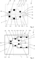
- FIG. 2 and 3 is a schematic diagram of a device 1 according to the invention for controlling a fluid mass flow as a control current for a device for compressing a gaseous fluid from the level of the suction pressure to the level of the high pressure with an axial ambient pressure application on a front side of a piston-shaped closure element 3 within a housing 2, while the device 1 according to the invention in Fig. 4 with the closure element 3 and a receiving element 11 in a perspective view and in Fig. 5 in a plan view of the receiving element 11 without the housing 2.
- the in comparison to the in Fig. 1 Components identical to those of the prior art device 1' shown are each provided with the same reference numerals.
- the device 1 has the housing 2 with various fluid connections 2a, 2b, 2c, 2d.
- the fluid connections 2a, 2b, 2c, 2d are also to be understood as flow channels formed in the components of the device 1.
- the closure element 3 and the Fig. 2 not shown Receiving element 11 for the closure element 3 is integrated within the housing 2.
- the closure element 3 is designed with a primary segment 3-1 inside the receiving element 11 and with a secondary segment 3-2 inside the housing 2.
- the closure element 3 is arranged with the primary segment 3-1 inside the receiving element 11 and the receiving element 11 inside the housing 2, while the closure element 3 is arranged with the secondary segment 3-2 inside the housing 2.
- the closure element 3 is formed integrally with the primary segment 3-1 and the secondary segment 3-2 in the shape of a cylinder, in particular a circular cylinder, with sections of different outer diameters.
- the device 1 has the flow path extending between the first fluid connection 2a at the level of the counter pressure and the second fluid connection 2b at the level of the high pressure of the device for compressing the gaseous fluid, the flow cross section of which can be regulated by the movement of the closure element 3.
- the control flow of the fluid is regulated by the closure element 3.
- the closure element 3 is located according to the Fig. 2 and 3 with the free first end face aligned in the direction of the longitudinal axis 3a, closes the flow path extending between the first fluid connection 2a and the second fluid connection 2b at a sealing seat 6.
- the sealing seat 6 is in Receiving element 11 of the device 1.
- the closure element 3 interacts with the sealing seat 6 and the second fluid connection 2b.
- the housing 2 also has the third fluid connection 2c with the fluid at the level of the suction pressure or the low pressure of the device for compressing the fluid, as well as the fourth fluid connection 2d with the level of the ambient pressure.
- the third fluid connection 2c and the fourth fluid connection 2d serve only to transfer the levels of the suction pressure and the ambient pressure to corresponding active surfaces of the closure element 3.
- first sealing elements 10-1 are arranged between the closure element 3 and the housing 2
- a second sealing element 10-2 is arranged between the closure element 3 and the receiving element 11
- third sealing elements 10-3 are arranged between the receiving element 11 and the housing 2, which each delimit volumes of the device 1 subjected to different pressures in the direction of the longitudinal axis 3a and seal them off from one another.
- the piston-shaped closure element 3 is subjected to ambient pressure on a second end face distal to the first end face aligned with the sealing seat 6.
- a volume delimited by the housing 2 and the second end face of the closure element 3 is subjected to the level of ambient pressure.
- the volume connected to the environment via the fourth fluid connection 2d thus has a pressure level that is independent of the level of low pressure and the level of counter pressure.
- the closure element 3 is geometrically designed such that the primary segment diameter d2, the sealing seat diameter d1, a first outer diameter d3 of the level of the suction pressure to the level of the counter pressure and a second outer diameter d4 of the level of the counter pressure to the level of the ambient pressure are configured such that a resulting force acts on the closure element 3 depending on the respective pressures applied and thus controls the control flow of the fluid from the second fluid connection 2b to the first fluid connection 2a.
- the closure element 3 is brought into the corresponding position by a force balance.
- the primary segment diameter d2 and the outer diameters d3, d4 of the closure element 3 are each configured such that the resulting level of the counter pressure is sufficient in particular for the required pressure of an orbiting spiral on a fixed spiral of a compression mechanism of a scroll compressor as a device for compressing a gaseous fluid.
- the device 1 is according to the Fig. 2 and 3 also formed with the first fluid connection 7, which extends from the first fluid connection 2a to a volume enclosed by the closure element 3, in particular an active surface with the first outer diameter d3 of the level of the back pressure to the level of the suction pressure, and the housing 2, in order to include the level of the back pressure in the balance of forces on the closure element 3.
- the second fluid connection 8 is provided, which connects the first fluid connection 2a to the third fluid connection 2c and extends between the first fluid connection 2a and a volume enclosed by the closure element 3, in particular an active surface with the first outer diameter d3 of the level of the suction pressure to the level of the back pressure, and the housing 2.
- the expansion element 9 is arranged within the second fluid connection 8.
- the volume enclosed by the closure element 3, in particular the second end face with the effective surface with the second outer diameter d4 and the housing 2, and connected to the fourth fluid connection 2d and thus subjected to the level of the ambient pressure, serves to reduce the effective surface of the counterpressure acting in the closed position of the closure element 3.
- the level of high pressure prevailing in the second fluid connection 2b and the reduced level of counterpressure prevailing at the sealing seat 6 through the sealing gap formed between the closure element 3 and the receiving element 11 also act against the closed position of the closure element 3.
- the first sealing elements 10-1 designed as O-rings each form a fluid-tight and pressure-tight barrier between the volumes subjected to the level of the ambient pressure and the level of the counterpressure and between the volumes subjected to the level of the counterpressure and the level of the suction pressure, while the second sealing element 10-2 designed as an O-ring forms a fluid-tight and pressure-tight barrier between the volume subjected to the level of the suction pressure and the first fluid connection 2a.
- the first sealing element 10-1 provided between the volumes subjected to the level of the ambient pressure and the level of the counterpressure is designed to seal the device 1 from the environment.
- a device for compressing a gaseous fluid in particular an electrically driven compressor 20, specifically a scroll compressor, with an integrated device 1 for controlling a fluid mass flow as a control flow is shown in a lateral sectional view.
- the compressor 20 is designed with a compression mechanism 21 and an electric motor 22 for driving the compression mechanism 21.
- the housing 2 is formed from housing elements, in particular for accommodating the compression mechanism 21 and for accommodating the electric motor 22, and preferably from a metal, for example from aluminum.
- the electric motor 22 has a stator 22a with a substantially hollow cylindrical stator core and coils wound on the stator core as well as a rotor 22b arranged within the stator 22a.
- the rotor 22b is set in a rotational movement when electrical energy is supplied to the coils of the stator 22a.
- the rotor 22b is arranged coaxially within the stator 22a and rotatable about a rotation axis 23.
- a drive shaft 24 can be formed integrally with the rotor 22b or as a separate element.
- the orbiting spiral 21b of the compression mechanism 21, in which the gaseous fluid, specifically a refrigerant, is compressed, is driven via the drive shaft 24 connected to the rotor 22b of the electric motor 22.
- the fluid compressed to the high pressure level when flowing through the compression mechanism 21 is discharged through at least one outlet 25 from the compression mechanism 21 into a region of the high pressure level 20b of the compressor 20.
- the compressor 20 also has a wall arranged within the housing 2 and firmly connected to the housing 2, which is designed as a boundary of a region of the level of the back pressure 20a of the compressor 20, also known as the back pressure region, and is therefore also referred to as the counter wall 26.
- the counter wall 26 Within the space between the counter wall 26 and the orbiting spiral 21b, in particular a In the area of the level of the back pressure 20a formed on the back of a base plate of the orbiting spiral 21b, the fluid is at the level of the back pressure, which is also the level of the contact pressure as an intermediate pressure between the levels of the high pressure as the outlet pressure and the low pressure as the suction pressure of the compressor 20.
- the fluid has the level of the low pressure in an area of the level of the low pressure 20c of the compressor 20, in which the electric motor 22 is also arranged.
- the ambient pressure prevails outside the housing 2 of the compressor 20, so that the environment is also referred to as the area of the level of the ambient pressure 20d of the compressor 20.
- the device 1 for controlling a fluid mass flow is preferably integrated within a cavity of the housing 2 of the device for compressing a gaseous fluid, in particular the compressor 20.
- the first sealing elements 10-1 are arranged between the closure element 3 and the housing 2 and the second sealing element 10-2 is arranged between the closure element 3 and the receiving element 11, while pressure chambers formed between the receiving element 11 and the housing 2 are sealed from one another by the third sealing elements 10-3 formed as O-rings.
- the receiving element 11 of the closure element 3 of the device 1 is sealed from the housing 2 via the third sealing elements 10-3.
- the third sealing elements 10-3 each form a fluid-tight and pressure-tight barrier between volumes subjected to the level of suction pressure and the level of high pressure, in particular between the area of the level of low pressure 20c and the area of the level of high pressure 20b of the compressor 20, and between volumes subjected to the level of high pressure and the level of counterpressure, in particular between the area of the level of high pressure 20b and the area of the level of counterpressure 20a of the compressor 20.
- the areas of the level of counterpressure 20a are connected to one another via the first fluid connection 7.
Landscapes
- Engineering & Computer Science (AREA)
- General Engineering & Computer Science (AREA)
- Mechanical Engineering (AREA)
- Physics & Mathematics (AREA)
- Fluid Mechanics (AREA)
- General Physics & Mathematics (AREA)
- Automation & Control Theory (AREA)
- Thermal Sciences (AREA)
- Rotary Pumps (AREA)
- Control Of Fluid Pressure (AREA)
Abstract
Vorrichtung (1) zum Steuern eines Fluidmassenstroms für einen Verdichter von einem Niveau eines Niederdrucks auf ein Niveau eines Hochdrucks mit einem Gehäuse (2) mit auf unterschiedlichen Druckniveaus beaufschlagten Fluidanschlüssen (2a, 2b, 2c, 2d) und einem innerhalb des Gehäuses (2) entlang einer Längsachse (3a) translatorisch bewegbar angeordneten Verschlusselement (3) mit den Fluidanschlüssen (2a, 2b, 2c, 2d) zugeordneten Wirkflächen. Das Verschlusselement (3) ist derart ausgebildet, einen Strömungsquerschnitt eines sich zwischen einem ersten Fluidanschluss (2a) und einem zweiten Fluidanschluss (2b) erstreckenden Strömungspfades zu regeln. Die Vorrichtung (1) weist ein Aufnahmeelement (11) zur Aufnahme des Verschlusselements (3) auf. Ein Primärsegment (3-1) als ein erster Abschnitt des Verschlusselements (3) vom Aufnahmeelement (11) und ein Sekundärsegment (3-2) als ein zweiter Abschnitt des Verschlusselements (3) vom Gehäuse (2) sowie das Aufnahmeelement (11) vom Gehäuse (2) sind jeweils vollumfänglich umschlossen angeordnet. Zudem sind das Sekundärsegment (3-2) über mindestens ein erstes Dichtelement (10-1) zum Gehäuse (2) und das Primärsegment (3-1) des Verschlusselements (3) über mindestens ein zweites Dichtelement (10-2) zum Aufnahmeelement (11) sowie das Aufnahmeelement (11) über mindestens ein drittes Dichtelement (10-3) zum Gehäuse (2) jeweils fluiddicht und druckdicht abgedichtet.
Description
- Die Erfindung betrifft eine Vorrichtung zum Steuern eines Fluidmassenstroms als Steuerstrom für eine Vorrichtung zum Verdichten eines gasförmigen Fluids, insbesondere ein Regelventil für einen Scrollverdichter. Die Vorrichtung zum Steuern des Steuermassenstroms weist ein Gehäuse mit auf unterschiedlichen Druckniveaus beaufschlagten Fluidanschlüssen und ein innerhalb des Gehäuses entlang einer Längsachse translatorisch bewegbares Verschlusselement mit den Fluidanschlüssen zugeordneten Wirkflächen auf. Das Verschlusselement ist derart ausgebildet, einen Strömungsquerschnitt eines sich zwischen einem ersten Fluidanschluss und einem zweiten Fluidanschluss erstreckenden Strömungspfades zu regeln.
- Die Erfindung betrifft zudem eine Vorrichtung zum Verdichten eines gasförmigen Fluids, insbesondere einen Scrollverdichter zum Verdichten eines Kältemittels, welche ein Gehäuse mit einer Gegenwandung und einen Verdichtungsmechanismus mit einer unbeweglichen, feststehenden Spirale sowie einer über einen Exzenterantrieb angetriebenen beweglichen, orbitierenden Spirale aufweist. Der Scrollverdichter wird auch als Spiralverdichter bezeichnet.
- Aus dem Stand der Technik bekannte Verdichter für mobile Anwendungen, insbesondere für Klimatisierungssysteme von Kraftfahrzeugen, zum Fördern von Kältemittel durch einen Kältemittelkreislauf, auch als Kältemittelverdichter bezeichnet, werden unabhängig vom Kältemittel oft als Kolbenverdichter mit variablem Hubvolumen oder als Scrollverdichter ausgebildet. Die Verdichter werden dabei entweder über eine Riemenscheibe oder elektrisch angetrieben.
- Herkömmliche Scrollverdichter weisen neben einem Gehäuse, eine unbewegliche, feststehende Spirale mit einer scheibenförmigen Grundplatte und einer sich von einer Seite der Grundplatte erstreckenden, spiralförmigen Wandung sowie eine bewegliche, orbitierende Spirale ebenfalls mit einer scheibenförmigen Grundplatte und einer sich von einer Vorderseite der Grundplatte erstreckenden, spiralförmigen Wandung auf. Dabei sind die Grundplatten derart zueinander angeordnet, dass die spiralförmigen Wandungen in axialer Richtung ineinandergreifen.
- Die feststehende Spirale und die orbitierende Spirale wirken zusammen. Dabei wird die orbitierende Spirale mittels eines Exzenterantriebs auf einer kreisförmigen Bahn derart bewegt, dass sich die spiralförmigen Wandungen an mehreren Stellen berühren und zwischen den Wandungen und den Grundplatten mehrere aufeinanderfolgende, abgeschlossene Arbeitsräume ausgebildet sind. Die Volumina benachbart angeordneter Arbeitsräume sind unterschiedlich groß. Infolge der Bewegung der orbitierenden Spirale relativ zur feststehenden Spirale werden die Volumina und die Positionen der Arbeitsräume derart verändert, dass die Volumina der Arbeitsräume zur Mitte der spiralförmigen Wandungen hin zunehmend kleiner werden und ein innerhalb der Arbeitsräume eingeschlossenes gasförmiges Fluid verdichtet wird. Das derart verdichtete Fluid wird durch mindestens einen Auslass aus dem Verdichtungsmechanismus ausgelassen. Der damit verbundene Anstieg des Drucks in benachbart angeordneten Arbeitsräumen verursacht eine auf die orbitierende Spirale, vorwiegend in axialer Richtung, wirkende Kraft, welche zudem außermittig auf die orbitierende Spirale einwirkt und derart ein Kippmoment erzeugt.
- Zudem sollten für eine ausreichende innere Dichtheit in axialer Richtung ausgebildete Spalte zwischen der feststehenden Spirale und der orbitierenden Spirale minimal sein, was auch in Verbindung mit einem Anpressen der orbitierenden Spirale an die feststehende Spirale gewährleistet wird.
- Die zum Stand der Technik gehörenden Scrollverdichter weisen dabei eine innerhalb des Gehäuses angeordnete und fest mit dem Gehäuse verbundene Wandung auf, welche als Begrenzung eines Gegendruckbereichs ausgebildet ist und folglich auch als Gegenwandung bezeichnet wird. Aufgrund des innerhalb des zwischen der Gegenwandung und der orbitierenden Spirale, insbesondere einer Rückseite der Grundplatte der orbitierenden Spirale, ausgebildeten Gegendruckbereichs, auch als Gegendruckkammer bezeichnet, vorherrschenden Gegendrucks wird die orbitierende Spirale mit einer in axialer Richtung wirkenden Kraft gegen die, ebenso wie die Gegenwandung am Gehäuse fixierte, feststehende Spirale gedrückt. Die in der axialen Richtung wirkende Druckkraft wird durch den innerhalb des Gegendruckbereichs vorherrschenden Gegendruck, auch als Anpressdruck bezeichnet, geregelt. Dabei liegt das Niveau des Anpressdrucks als ein Zwischendruck beziehungsweise Mitteldruck zwischen den Niveaus des Hochdrucks als Auslassdruck und des Niederdrucks als Saugdruck des Verdichters. Der Wert des Anpressdrucks ist derart einzustellen, dass einerseits die axialen Dichtflächen zwischen orbitierender Spirale und feststehender Spirale geschlossen sind und anderseits eine übermäßige, Verschleiß verursachende Reibung zwischen der feststehenden Spirale und der orbitierenden Spirale vermieden wird.
- Die mit Hochdruck und Gegendruck sowie mit Gegendruck und Niederdruck beaufschlagten Bereiche des Verdichters können jeweils über Strömungskanäle mit integrierten Expansionsvorrichtungen miteinander verbunden sein. Durch die Strömungskanäle strömt ein sehr begrenzter Massenstrom des im Verdichter verdichteten Fluids beziehungsweise eines Gemisches aus dem Fluid und Öl als Schmiermittel des Verdichters, welcher auch als Steuermassenstrom bezeichnet wird. Herkömmliche Expansionsvorrichtungen sind jeweils als Düsen ausgebildet. Dabei kann zumindest eine Expansionsvorrichtung auch als ein federbelastetes mechanisches Regelventil ausgebildet sein.
- Aus der
DE 10 2016 105 302 A1 geht ein Steuerstromregelventil für Spiralverdichter in Klimatisierungssystemen für Kraftfahrzeuge hervor. Das Steuerstromregelventil weist ein Gehäuse und ein innerhalb des Gehäuses angeordnetes Verschlusselement zum Einstellen des Steuerstroms auf. Das Gehäuse ist mit Fluidanschlüssen für den Hochdruck, den Gegendruck und den Saugdruck sowie den Umgebungsdruck ausgebildet. Das Verschlusselement für den Steuerstrom weist den jeweiligen Fluidanschlüssen zugeordnete Wirkflächen auf. Dabei wirkt eine aus den am Verschlusselement anliegenden Drücken resultierende Kraft auf das Verschlusselement derart ein, dass von einem mit Fluid auf Hochdruck beaufschlagten Bereich zu einem mit Fluid auf Saugdruck beaufschlagten Bereich ein Gegendruck erzeugender Steuerstrom strömt. Zudem ist ein fluiddichter, mit Umgebungsdruck beaufschlagter Bereich ausgebildet, welcher mittels einer an das metallische Verschlusselement angeschweißten Blechmembran oder anvulkanisierten Membran abgedichtet ist. Innerhalb des Gehäuses ist zudem ein Federelement zum Erzeugen einer zusätzlichen, auf das Verschlusselement wirkenden Kraft angeordnet. - Das Kräftegleichgewicht am Verschlusselement und die Stellung des Verschlusselements zum Erreichen einer erforderlichen Regelkurve des Gegendrucks abhängig von dem Hochdruck und dem Saugdruck beziehungsweise Niederdruck, wird durch die an den Wirkflächen anliegenden Drücke sowie den Durchfluss durch eine vom Verschlusselement freigegebene Durchlassöffnung beeinflusst.
- Das Steuerstromregelventil weist zwei Elastomermembrane auf, welche auf der Niederdruckseite und der Gegendruckseite ausgebildet sind. Die Elastizität der Elastomermembrane ermöglicht eine axiale Beweglichkeit des Verschlusselements innerhalb des Gehäuses. Die Elastomermembrane begrenzen einen Bereich des Steuerstromregelventils in axialer Richtung, welcher aufgrund einer Verbindung zum Umgebungsdruck einen vom Niederdruck und vom Gegendruck unabhängigen atmosphärischen Druck aufweist. Mit den Elastomermembranen ist zwischen der Niederdruckseite und der Gegendruckseite eine fluiddichte und druckdichte Barriere ausgebildet. Die fluiddichte Anbindung der Elastomermembrane wird durch Anvulkanisieren an dem umliegenden Gehäuse oder dem Verschlusselement gewährleistet.
- Die aus dem Stand der Technik bekannten Vorrichtungen zum Steuern eines Fluidmassenstroms als Steuerstrom, insbesondere für eine Vorrichtung zum Verdichten eines gasförmigen Fluids, weisen eine große Anzahl, in einer komplexen Struktur miteinander verbundene Komponenten auf, was eine hohe Komplexität bei der Montage mit einer hohen Anzahl an Montageschritten und damit hohe Montagekosten verursacht. So sind beispielsweise mehrere Dichtungen erforderlich, um verschiedene Druckstufen voneinander zu trennen. Zudem birgt die große Anzahl der Komponenten eine hohe Gefahr an Fehlern während des Montageprozesses. Des Weiteren ist beispielsweise das Anvulkanisieren der Membrane aus einem Elastomer an Metall sehr aufwändig und komplex sowie insbesondere für Hochdruckanwendungen, wie bei Systemen für Kohlenstoffdioxid als Fluid, ungeeignet. Das Abdichten mit anvulkanisierten Membranen bewirkt zudem eine hohe Permeationsfläche, was über eine Gesamtbetriebsdauer zu einem sehr hohen Austritt des Fluids in die Umgebung und damit einem sehr hohen Verlust des Fluids führen kann.
- Um die Vorrichtung, speziell das Verschlusselement, auf den entsprechenden Arbeitspunkt einzustellen und eine hohe Reproduzierbarkeit zu erreichen, ist der Dichtsitz zu prägen. Dabei wird beim Prägen mittels einer Presse eine definierte Kraft auf das Verschlusselement aufgebracht, sodass sich am Gehäuse durch plastische Verformung des Materials ein entsprechender Dichtsitz ausbildet. Der Prägevorgang besteht meist aus einer Iteration von Prägeschritten und Testen, bis ein gewünschtes Druckniveau eingeregelt wird, und dient beispielsweise gemäß der
DE 10 2016 105 302 A1 zum Einstellen einer Distanz zwischen dem Verschlusselement und den Elastomermembranen, um durch Auslengung auftretende Spannungen der Elastomermembrane zu eliminieren. - Die Aufgabe der Erfindung besteht im Bereitstellen einer Vorrichtung zum Steuern eines Fluidmassenstroms als Steuerstrom für eine Vorrichtung zum Verdichten eines gasförmigen Fluids, insbesondere um einen störungsfreien Betrieb mit maximaler Lebensdauer der Vorrichtung zum Verdichten des Fluids zu gewährleisten. Die Vorrichtung soll eine minimale Anzahl an Einzelkomponenten aufweisen und konstruktiv einfach realisierbar sein, auch, um den Montageaufwand und die Kosten bei der Montage zu minimeren. Die Vorrichtung soll fluiddicht ausgebildet sein, um die Leckage beziehungsweise den Austritt von Fluid in die Umgebung und damit den Verlust an Fluid aus einem System zu verhindern.
- Die Aufgabe wird durch die Gegenstände mit den Merkmalen der selbstständigen Patentansprüche gelöst. Weiterbildungen sind in den abhängigen Patentansprüchen angegeben.
- Die Aufgabe wird durch eine erfindungsgemäße Vorrichtung zum Steuern eines Fluidmassenstroms als ein Steuerstrom für eine Vorrichtung zum Verdichten eines gasförmigen Fluids von einem Niveau eines Niederdrucks auf ein Niveau eines Hochdrucks gelöst. Die Vorrichtung zum Steuern eines Fluidmassenstroms weist ein Gehäuse mit auf unterschiedlichen Druckniveaus beaufschlagten Fluidanschlüssen und ein innerhalb des Gehäuses entlang einer Längsachse translatorisch bewegbar angeordnetes Verschlusselement mit den Fluidanschlüssen zugeordneten Wirkflächen auf. Das Verschlusselement ist dabei derart ausgebildet, einen Strömungsquerschnitt eines sich zwischen einem ersten Fluidanschluss und einem zweiten Fluidanschluss erstreckenden Strömungspfades zu regeln.
- Nach der Konzeption der Erfindung weist die Vorrichtung ein Aufnahmeelement zur Aufnahme des Verschlusselements auf. Ein Primärsegment ist als ein erster Abschnitt des Verschlusselements vom Aufnahmeelement und ein Sekundärsegment ist als ein zweiter Abschnitt des Verschlusselements vom Gehäuse jeweils vollumfänglich umschlossen. Zudem ist das Aufnahmeelement vom Gehäuse vollumfänglich umschlossen. Dabei sind das Sekundärsegment des Verschlusselements über mindestens ein erstes Dichtelement zum Gehäuse und das Primärsegment des Verschlusselements über mindestens ein zweites Dichtelement zum Aufnahmeelement sowie das Aufnahmeelement über mindestens ein drittes Dichtelement zum Gehäuse jeweils fluiddicht und druckdicht abgedichtet.
- Das Verschlusselement ist mit dem Primärsegment und dem Sekundärsegment vorteilhaft als eine zusammenhängende Einheit einstückig ausgebildet. Das Verschlusselement und das Aufnahmeelement können dabei jeweils eine metallische oder eine nichtmetallische Komponente sein. Die Dichtelemente sind vorzugsweise jeweils als eine O-Ring-Dichtung ausgebildet.
- Nach einer Weiterbildung der Erfindung sind der erste Fluidanschluss des Gehäuses mit dem Fluid auf einem Niveau eines Gegendrucks und der zweite Fluidanschluss des Gehäuses mit dem Fluid auf dem Niveau des Hochdrucks beaufschlagt, während ein dritter Fluidanschluss des Gehäuses mit dem Fluid auf dem Niveau des Niederdrucks beaufschlagt ist. Dabei stellt das Niveau des Gegendrucks ein Zwischendruckniveau zwischen dem Niveau des Niederdrucks und dem Niveau des Hochdrucks des Fluids dar. Ein vierter Fluidanschluss des Gehäuses ist vorzugsweise mit einem Niveau des Umgebungsdrucks, insbesondere der Umgebungsluft, beaufschlagt.
- Nach einer bevorzugten Ausgestaltung der Erfindung ist das Verschlusselement zylinderförmig, insbesondere kreiszylinderförmig, mit Abschnitten unterschiedlicher Außendurchmesser ausgebildet, sodass das Verschlusselement zwischen benachbarten Abschnitten Abstufungen aufweist.
- Ein Vorteil der Erfindung besteht darin, dass das Verschlusselement an einer ersten Stirnseite, insbesondere einer Stirnseite des Primärsegments, mit dem Aufnahmeelement einen Dichtsitz ausbildet.
- Ein vom Gehäuse und einer zur ersten Stirnseite distalen zweiten Stirnseite des Verschlusselements, insbesondere einer Stirnseite des Sekundärsegments, begrenztes Volumen ist vorzugsweise mit dem Niveau des Umgebungsdrucks, insbesondere mit Umgebungsluft, beaufschlagt und über den vierten Fluidanschluss des Gehäuses mit der Umgebung verbunden.
- Nach einer vorteilhaften Ausgestaltung der Erfindung sind das Primärsegment des Verschlusselements mit einem Primärsegmentdurchmesser und das Sekundärsegment des Verschlusselements mit mindestens zwei Abschnitten mit jeweils unterschiedlichen Außendurchmessern ausgebildet. Dabei können sich jeweils auch der Primärsegmentdurchmesser und die Außendurchmesser des Sekundärsegments des Verschlusselements voneinander unterscheiden.
- Nach einer weiteren bevorzugten Ausgestaltung der Erfindung ist ein von dem Gehäuse, dem Aufnahmeelement und dem Verschlusselement mit einer kreisringförmigen Wirkfläche mit einem ersten Außendurchmesser des Verschlusselements und dem Primärsegmentdurchmesser des Verschlusselements als Innendurchmesser begrenztes Volumen mit dem Fluid auf dem Niveau des Niederdrucks beaufschlagt und mit dem dritten Fluidanschluss des Gehäuses verbunden.
- Des Weiteren ist vorteilhaft ein von dem Gehäuse und dem Verschlusselement mit einer kreisringförmigen Wirkfläche mit dem ersten Außendurchmesser des Verschlusselements und einem zweiten Außendurchmesser des Verschlusselements als Innendurchmesser begrenztes Volumen mit dem Fluid auf dem Niveau des Gegendrucks beaufschlagt und mit dem ersten Fluidanschluss des Gehäuses verbunden.
- Nach einer Weiterbildung der Erfindung ist innerhalb des Gehäuses eine erste Fluidverbindung ausgebildet, welche sich vom ersten Fluidanschluss bis zum von dem Gehäuse und dem Verschlusselement mit der kreisringförmigen Wirkfläche mit dem ersten Außendurchmesser des Verschlusselements und dem zweiten Außendurchmesser des Verschlusselements als Innendurchmesser begrenzten Volumen erstreckt.
- Innerhalb des Gehäuses kann zudem eine zweite Fluidverbindung vorgesehen sein, welche sich vom ersten Fluidanschluss zum von dem Gehäuse und dem Verschlusselement mit der kreisringförmigen Wirkfläche mit dem ersten Außendurchmesser des Verschlusselements und dem Primärsegmentdurchmesser des Verschlusselements als Innendurchmesser begrenzten Volumen beziehungsweise zum dritten Fluidanschluss des Gehäuses erstreckt. Die zweite Fluidverbindung ist vorteilhaft mit einem Expansionselement, insbesondere einem Drosselorgan, ausgebildet.
- Die Vorrichtung zum Steuern des Fluidmassenstroms als Steuerstrom ist vorteilhaft derart konfiguriert, dass die translatorische Bewegung des Verschlusselements innerhalb des Gehäuses und des Aufnahmeelements ausschließlich auf an den Wirkflächen des Verschlusselements wirkenden Drücken und damit auf Druckkräften basiert. Die definierten Druckkräfte beziehungsweise Kolbenkräfte verursachen die Bewegung des Verschlusselements innerhalb gleitend dichtender, insbesondere als O-Ringe ausgebildeter Dichtelemente.
- Die Aufgabe wird auch durch eine erfindungsgemäße Vorrichtung zum Verdichten eines gasförmigen Fluids von einem Niveau eines Niederdrucks auf ein Niveau eines Hochdrucks, insbesondere einen Scrollverdichter zum Verdichten eines Kältemittels, gelöst. Dabei liegt das zu verdichtende Fluid in einem Ansaugbereich auf dem Niveau des Niederdrucks und das verdichtete Fluid in einem Hochdruckbereich, speziell an einem Auslass der Vorrichtung zum Verdichten, auf dem Niveau des Hochdrucks vor. Die Vorrichtung zum Verdichten weist ein Gehäuse mit einer Gegenwandung und einen Verdichtungsmechanismus mit einer unbeweglichen, feststehenden Spirale sowie einer über einen Exzenterantrieb angetriebenen beweglichen, orbitierenden Spirale auf. Das Gehäuse mit der Gegenwandung und die orbitierende Spirale umschließen zumindest bereichsweise gemeinsam eine Gegendruckkammer. Zudem ist ein sich vom Hochdruckbereich zur Gegendruckkammer erstreckender Strömungspfad ausgebildet.
- Nach der Konzeption der Erfindung ist innerhalb des sich zwischen dem Hochdruckbereich und der Gegendruckkammer erstreckenden Strömungspfades eine erfindungsgemäße Vorrichtung zum Steuern eines Fluidmassenstroms ausgebildet.
- Die vorteilhafte Ausgestaltung der Erfindung ermöglicht die Verwendung der Vorrichtung zum Verdichten des gasförmigen Fluids mit der Vorrichtung zum Steuern eines Fluidmassenstroms als Verdichter in einem Kältemittelkreislauf eines Klimatisierungssystems eines Kraftfahrzeugs. Der Verdichter kann dabei elektrisch oder mechanisch angetrieben ausgebildet sein. Dabei wird der Verdichtungsmechanismus mittels eines Elektromotors oder einer Riemenscheibe angetrieben.
- Die erfindungsgemäße Vorrichtung zum Steuern eines Fluidmassenstroms als Steuerstrom für eine Vorrichtung zum Verdichten eines gasförmigen Fluids von einem Niveau eines Niederdrucks auf ein Niveau eines Hochdrucks kann folglich als ein Steuerstromregelventil, insbesondere eines Scrollverdichters eines Kältemittelkreislaufs eines Klimatisierungssystems eines Kraftfahrzeugs, ausgebildet sein.
- Die erfindungsgemäße Vorrichtung zum Steuern eines Fluidmassenstroms und die Vorrichtung zum Verdichten eines gasförmigen Fluids mit der erfindungsgemäßen Vorrichtung zum Steuern eines Fluidmassenstroms weisen zusammenfassend weitere diverse Vorteile auf:
- minimale Anzahl an Einzelkomponenten und einfache Konstruktion, dadurch minimaler Montageaufwand, Fertigungsaufwand und Wartungsaufwand sowie minimale Montagekosten, Fertigungskosten und Wartungskosten,
- beispielsweise wird das im Vergleich zum Stand der Technik in der Vorrichtung vorgesehene Federelement nicht benötigt und der Dichtsitz ist ohne einen zusätzlichen Formgebungsschritt in das Aufnahmeelement integriert, sowie
- maximale Funktionssicherheit und Dichtheit durch minimale Anzahl potentieller Leckagepfade zur Umgebung - es ist lediglich eine Dichtstelle zur Umgebung vorhanden, dadurch minimaler Kältemittelaustritt aus der Vorrichtung zum Verdichten.
- Weitere Einzelheiten, Merkmale und Vorteile der Erfindung ergeben sich aus der nachfolgenden Beschreibung eines Ausführungsbeispiels mit Bezugnahme auf die zugehörigen Zeichnungen. Es zeigen:
- Fig. 1:
- ein Prinzipschaltbild einer Vorrichtung zum Steuern eines Fluidmassenstroms als Steuerstrom für eine Vorrichtung zum Verdichten eines gasförmigen Fluids mit einer radialen Umgebungsdruckbeaufschlagung aus dem Stand der Technik,
- Fig. 2 und 3:
- jeweils ein Prinzipschaltbild einer erfindungsgemäßen Vorrichtung zum Steuern eines Fluidmassenstroms als Steuerstrom für eine Vorrichtung zum Verdichten eines gasförmigen Fluids,
- Fig. 4:
- die erfindungsgemäße Vorrichtung mit einem Verschlusselement und einem Aufnahmeelement in einer perspektivischen Darstellung und
- Fig. 5:
- die Vorrichtung aus
Fig. 4 in einer Draufsicht sowie - Fig. 6:
- eine Vorrichtung zum Verdichten eines gasförmigen Fluids mit integrierter Vorrichtung zum Steuern eines Fluidmassenstroms als Steuerstrom in einer seitlichen Schnittdarstellung.
- Aus
Fig. 1 geht ein Prinzipschaltbild einer Vorrichtung 1' zum Steuern eines Fluidmassenstroms als Steuerstrom, auch als Steuerstromregelventil bezeichnet, für eine Vorrichtung zum Verdichten eines gasförmigen Fluids von einem Niveau eines Saugdrucks auf ein Niveau eines Hochdrucks mit einer radialen Umgebungsdruckbeaufschlagung aus dem Stand der Technik hervor. - Die Vorrichtung 1' weist ein Gehäuse 2` mit verschiedenen Fluidanschlüssen 2a', 2b', 2c', 2d' auf. Innerhalb des Gehäuses 2` ist ein Verschlusselement 3' entlang einer Längsachse 3a, welche einer Symmetrieachse des Verschlusselements 3' entspricht, translatorisch bewegbar angeordnet. Die Vorrichtung 1' ist mit einem Strömungspfad ausgebildet, welcher sich von einem ersten Fluidanschluss 2a' bis zu einem zweiten Fluidanschluss 2b' erstreckt und dessen Strömungsquerschnitt mittels des Verschlusselements 3` regelbar ist. Dabei wird mittels des Verschlusselements 3' ein Steuerstrom des Fluids von einem Niveau des Hochdrucks am zweiten Fluidanschluss 2b` auf ein Niveau eines Gegendrucks am ersten Fluidanschluss 2a' geregelt.
- Zudem weist das Gehäuse 2` einen dritten Fluidanschluss 2c' mit dem Fluid auf einem Niveau des Saugdrucks der Vorrichtung zum Verdichten des Fluids, auch als Niveau des Niederdrucks bezeichnet, sowie einen vierten Fluidanschluss 2d' mit einem Niveau des Umgebungsdrucks auf. Dabei bilden der dritte Fluidanschluss 2c' und der vierte Fluidanschluss 2d' jeweils keinen Strömungspfad aus. Der dritte Fluidanschluss 2c' und der vierte Fluidanschluss 2d' dienen dem Übertragen der Niveaus des Saugdrucks und des Umgebungsdrucks auf entsprechende Wirkflächen des Verschlusselements 3'.
- Zwischen dem Verschlusselement 3' und dem Gehäuse 2` sind Membrandichtelemente 4' angeordnet, welche einen Bereich der Vorrichtung 1' in Richtung der Längsachse 3a begrenzen und die Vorrichtung 1' zum Umgebungsdruck abdichten. Der von den Membrandichtelementen 4' begrenzte Bereich weist aufgrund einer Verbindung zum Niveau des Umgebungsdrucks einen vom Niederdruck und vom Gegendruck unabhängigen atmosphärischen Druck auf. Die Membrandichtelemente 4' bilden in Kombination eine fluiddichte und druckdichte Barriere zwischen der mit dem dritten Fluidanschluss 2c' verbundenen Niederdruckseite und der mit dem ersten Fluidanschluss 2a' verbundenen Gegendruckseite aus.
- Aufgrund der zwischen dem Verschlusselement 3' und dem Gehäuse 2` jeweils als eine geschweißte Blechmembran oder eine anvulkanisierte Membran ausgebildeten Membrandichtelemente 4' besteht ein hohes Risiko an Leckage und damit die Gefahr, dass Fluid über den vierten Fluidanschluss 2d' in die Umgebung ausströmt. Die Vorrichtung 1' weist dabei vier potenzielle Leckagepfade für das Fluid in die Umgebung auf. Die jeweils aus einem Elastomer ausgebildeten Membrandichtelemente 4' sind am Verschlusselement 3' anvulkanisiert.
- In einer in
Fig. 1 gezeigten Schließstellung der Vorrichtung 1' liegt das Verschlusselement 3' an einem am Gehäuse 2' ausgebildeten Dichtsitz 6 mit einem Dichtsitzdurchmesser d1 an. Der Dichtsitz 6 ist zwischen dem ersten Fluidanschluss 2a' und dem zweiten Fluidanschluss 2b` ausgebildet. Der sich zwischen den Fluidanschlüssen 2a`, 2b' erstreckende Strömungspfad ist geschlossen. Bei einer von der Schließstellung abweichenden Stellung der Vorrichtung 1' strömt das Fluid vom zweiten Fluidanschluss 2b' zum ersten Fluidanschluss 2a' durch den Strömungspfad. Dabei wird mit dem geregelten, engen Dichtsitz 6 ein Strömungswiderstand erzeugt, welcher einen Druckverlust des Fluids bewirkt. - Die Vorrichtung 1' weist zudem ein Federelement 5' auf, welches mit einer entgegen der Schließstellung des Verschlusselements 3' ausgerichteten Federkraft auf das Verschlusselement 3' einwirkend angeordnet ist. Das Federelement 5' ist folglich für ein Öffnen der Vorrichtung 1', insbesondere des sich zwischen dem ersten Fluidanschluss 2a' und dem zweiten Fluidanschluss 2b` erstreckenden Strömungspfades, ausgebildet, wenn die auf das Verschlusselement 3' aufgrund der unterschiedlichen Drücke einwirkenden Kräfte ausgeglichen sind.
- Das Verschlusselement 3` liegt mit einer in Richtung der Längsachse 3a ausgerichteten freien Stirnseite eines Primärsegments 3-1' den sich zwischen dem ersten Fluidanschluss 2a' und dem zweiten Fluidanschluss 2b` erstreckenden Strömungspfad verschließend am Dichtsitz 6 an. Das Primärsegment 3-1' des Verschlusselements 3' wirkt mit dem Dichtsitz 6 und dem zweiten Fluidanschluss 2b` zusammen.
- Das Verschlusselement 3' ist geometrisch derart ausgebildet, dass ein Primärsegmentdurchmesser d2, der Dichtsitzdurchmesser d1, ein erster Wirkdurchmesser d3` des Niveaus des Saugdrucks zum Niveau des Umgebungsdrucks und ein zweiter Wirkdurchmesser d4' des Niveaus des Gegendrucks zum Niveau des Umgebungsdrucks derart konfiguriert sind, dass eine resultierende Kraft abhängig von den jeweils anliegenden Druckniveaus auf das Verschlusselement 3' einwirkt und damit den Steuerstrom des Fluids vom zweiten Fluidanschluss 2b' zum ersten Fluidanschluss 2a' steuert. Durch ein Kräftegleichgewicht wird das Verschlusselement 3' jeweils in die entsprechende Position verbracht.
- Die Vorrichtung 1' ist zudem mit einer ersten Fluidverbindung 7 ausgebildet, welche sich vom ersten Fluidanschluss 2a' bis zu einem vom Verschlusselement 3', insbesondere einer Wirkfläche mit dem zweiten Wirkdurchmesser d4' des Niveaus des Gegendrucks zum Niveau des Umgebungsdrucks, und dem Gehäuse 2` umschlossenen Volumen erstreckt, um das Niveau des Gegendrucks entsprechend in das Kräftegleichgewicht am Verschlusselement 3' einzubeziehen. Zudem ist eine zweite Fluidverbindung 8 vorgesehen, welche den ersten Fluidanschluss 2a' mit dem dritten Fluidanschluss 2c' verbindet und sich zwischen dem ersten Fluidanschluss 2a' und einem vom Verschlusselement 3', insbesondere einer Wirkfläche mit dem ersten Wirkdurchmesser d3` des Niveaus des Saugdrucks zum Niveau des Umgebungsdrucks, und dem Gehäuse 2` umschlossenen Volumen erstreckt. Innerhalb der zweiten Fluidverbindung 8 ist ein Expansionselement 9, speziell ein Drosselelement beziehungsweise eine Drossel, angeordnet.
- Das Primärsegment 3-1' des Verschlusselements 3' ist mittels eines als O-Ring ausgebildeten Dichtelements 10` zum Gehäuse 2' abgedichtet.
- In den
Fig. 2 und 3 ist jeweils ein Prinzipschaltbild einer erfindungsgemäßen Vorrichtung 1 zum Steuern eines Fluidmassenstroms als Steuerstrom für eine Vorrichtung zum Verdichten eines gasförmigen Fluids vom Niveau des Saugdrucks auf das Niveau des Hochdrucks mit einer axialen Umgebungsdruckbeaufschlagung an einer Stirnseite eines kolbenförmigen Verschlusselements 3 innerhalb eines Gehäuses 2 gezeigt, während die erfindungsgemäße Vorrichtung 1 inFig. 4 mit dem Verschlusselement 3 und einem Aufnahmeelement 11 in einer perspektivischen Darstellung und inFig. 5 in einer Draufsicht auf das Aufnahmeelement 11 jeweils ohne das Gehäuse 2 gezeigt ist. Die im Vergleich zur inFig. 1 dargestellten Vorrichtung 1' aus dem Stand der Technik gleichen Komponenten sind jeweils mit gleichen Bezugszeichen versehen. - Die Vorrichtung 1 weist das Gehäuse 2 mit verschiedenen Fluidanschlüssen 2a, 2b, 2c, 2d auf. Unter den Fluidanschlüssen 2a, 2b, 2c, 2d sind ebenso in den Komponenten der Vorrichtung 1 ausgebildete Strömungskanäle zu verstehen. Das Verschlusselement 3 und das in
Fig. 2 nicht dargestellte Aufnahmeelement 11 für das Verschlusselement 3 sind innerhalb des Gehäuses 2 integriert. - Das jeweils bereichsweise innerhalb des Gehäuses 2 und des Aufnahmeelements 11 angeordnete Verschlusselement 3 ist entlang der Längsachse 3a als Symmetrieachse des Verschlusselements 3 translatorisch bewegbar. Das Verschlusselement 3 ist mit einem Primärsegment 3-1 innerhalb des Aufnahmeelements 11 und mit einem Sekundärsegment 3-2 innerhalb des Gehäuses 2 geführt ausgebildet. Dabei ist das Verschlusselement 3 mit dem Primärsegment 3-1 innerhalb des Aufnahmeelements 11 und das Aufnahmeelement 11 innerhalb des Gehäuses 2 angeordnet, während das Verschlusselement 3 mit dem Sekundärsegment 3-2 innerhalb des Gehäuses 2 angeordnet ist.
- Das Verschlusselement 3 ist mit dem Primärsegment 3-1 und dem Sekundärsegment 3-2 einstückig in der Form eines Zylinders, insbesondere eines Kreiszylinders, mit Abschnitten unterschiedlicher Außendurchmesser ausgebildet.
- Die Vorrichtung 1 weist den sich zwischen dem ersten Fluidanschluss 2a auf Niveau des Gegendrucks und dem zweiten Fluidanschluss 2b auf Niveau des Hochdrucks der Vorrichtung zum Verdichten des gasförmigen Fluids erstreckenden Strömungspfad auf, dessen Strömungsquerschnitt mit der Bewegung des Verschlusselements 3 regelbar ist. Mit dem Verschlusselement 3 wird der Steuerstrom des Fluids geregelt.
- Das Verschlusselement 3 liegt gemäß der
Fig. 2 und 3 mit der in Richtung der Längsachse 3a ausgerichteten freien ersten Stirnseite den sich zwischen dem ersten Fluidanschluss 2a und dem zweiten Fluidanschluss 2b erstreckenden Strömungspfad verschließend an einem Dichtsitz 6 an. Der Dichtsitz 6 ist im Aufnahmeelement 11 der Vorrichtung 1 ausgebildet. Das Verschlusselement 3 wirkt mit dem Dichtsitz 6 und dem zweiten Fluidanschluss 2b zusammen. - Das Gehäuse 2 weist ebenso den dritten Fluidanschluss 2c mit dem Fluid auf Niveau des Saugdrucks beziehungsweise des Niederdrucks der Vorrichtung zum Verdichten des Fluids sowie den vierten Fluidanschluss 2d mit dem Niveau des Umgebungsdrucks auf. Der dritte Fluidanschluss 2c und der vierte Fluidanschluss 2d dienen lediglich dem Übertragen der Niveaus des Saugdrucks und des Umgebungsdrucks auf entsprechende Wirkflächen des Verschlusselements 3.
- Zwischen dem Verschlusselement 3 und dem Gehäuse 2 sind zwei erste Dichtelemente 10-1, zwischen dem Verschlusselement 3 und dem Aufnahmeelement 11 ist ein zweites Dichtelement 10-2 und zwischen dem Aufnahmeelement 11 und dem Gehäuse 2 sind dritte Dichtelemente 10-3 angeordnet, welche jeweils mit unterschiedlichen Drücken beaufschlagte Volumina der Vorrichtung 1 in Richtung der Längsachse 3a begrenzen und zueinander abdichten.
- Das kolbenförmige Verschlusselement 3 ist an einer zur ersten, zum Dichtsitz 6 ausgerichteten Stirnseite distalen zweiten Stirnseite mit Umgebungsdruck beaufschlagt. Dabei ist ein durch das Gehäuse 2 und die zweite Stirnseite des Verschlusselements 3 begrenztes Volumen mit Niveau des Umgebungsdrucks beaufschlagt. Das über den vierten Fluidanschluss 2d mit der Umgebung verbundene Volumen weist damit ein vom Niveau des Niederdrucks und vom Niveau des Gegendrucks unabhängiges Druckniveau auf.
- In der in den
Fig. 2 und 3 dargestellten Schließstellung der Vorrichtung 1 liegt das Verschlusselement 3 jeweils an dem am Aufnahmeelement 11 ausgebildeten Dichtsitz 6 mit dem Dichtsitzdurchmesser d1 an. Der sich zwischen dem ersten Fluidanschluss 2a und dem zweiten Fluidanschluss 2b erstreckende Strömungspfad ist geschlossen. - Das Verschlusselement 3 ist geometrisch derart ausgebildet, dass der Primärsegmentdurchmesser d2, der Dichtsitzdurchmesser d1, ein erster Außendurchmesser d3 des Niveaus des Saugdrucks zum Niveau des Gegendrucks und ein zweiter Außendurchmesser d4 des Niveaus des Gegendrucks zum Niveau des Umgebungsdrucks derart konfiguriert sind, dass eine resultierende Kraft abhängig von den jeweils anliegenden Drücken auf das Verschlusselement 3 einwirkt und damit den Steuerstrom des Fluids vom zweiten Fluidanschluss 2b zum ersten Fluidanschluss 2a steuert. Durch ein Kräftegleichgewicht wird das Verschlusselement 3 jeweils in die entsprechende Position verbracht. Der Primärsegmentdurchmesser d2 und die Außendurchmesser d3, d4 des Verschlusselements 3 sind jeweils derart konfiguriert, dass das sich einstellende Niveau des Gegendrucks insbesondere dem benötigten Andruck einer orbitierenden Spirale an eine feststehende Spirale eines Verdichtungsmechanismus eines Scrollverdichters als eine Vorrichtung zum Verdichten eines gasförmigen Fluids genügt.
- Die Vorrichtung 1 ist gemäß der
Fig. 2 und 3 zudem mit der ersten Fluidverbindung 7 ausgebildet, welche sich vom ersten Fluidanschluss 2a bis zu einem vom Verschlusselement 3, insbesondere einer Wirkfläche mit dem ersten Außendurchmesser d3 des Niveaus des Gegendrucks zum Niveau des Saugdrucks, und dem Gehäuse 2 umschlossenen Volumen erstreckt, um das Niveau des Gegendrucks entsprechend in das Kräftegleichgewicht am Verschlusselement 3 einzubeziehen. Zudem ist die zweite Fluidverbindung 8 vorgesehen, welche den ersten Fluidanschluss 2a mit dem dritten Fluidanschluss 2c verbindet und sich zwischen dem ersten Fluidanschluss 2a und einem vom Verschlusselement 3, insbesondere einer Wirkfläche mit dem ersten Außendurchmesser d3 des Niveaus des Saugdrucks zum Niveau des Gegendrucks, und dem Gehäuse 2 umschlossenen Volumen erstreckt. Innerhalb der zweiten Fluidverbindung 8 ist das Expansionselement 9 angeordnet. - Das vom Verschlusselement 3, insbesondere der zweiten Stirnseite mit der Wirkfläche mit dem zweiten Außendurchmesser d4 und dem Gehäuse 2 umschlossene sowie mit dem vierten Fluidanschluss 2d verbundene und damit mit Niveau des Umgebungsdrucks beaufschlagte Volumen dient dem Reduzieren der Wirkfläche des in Schließstellung des Verschlusselements 3 wirkenden Gegendrucks.
- An der ersten Stirnseite des Verschlusselements 3 wirkt zudem entgegen der Schließstellung des Verschlusselements 3 das im zweiten Fluidanschluss 2b vorherrschende Niveau des Hochdrucks und das am Dichtsitz 6 durch zwischen dem Verschlusselement 3 und dem Aufnahmeelement 11 ausgebildeten Dichtspalt vorherrschende reduzierte Niveau des Gegendrucks.
- Die als O-Ringe ausgebildeten ersten Dichtelemente 10-1 bilden jeweils eine fluiddichte und druckdichte Barriere zwischen dem mit Niveau des Umgebungsdrucks und Niveau des Gegendrucks beaufschlagten Volumina sowie zwischen dem mit Niveau des Gegendrucks und Niveau des Saugdrucks beaufschlagten Volumina, während das als O-Ring ausgebildete zweite Dichtelement 10-2 eine fluiddichte und druckdichte Barriere zwischen dem mit Niveau des Saugdrucks beaufschlagten Volumen und dem ersten Fluidanschluss 2a bildet. Damit ist lediglich das zwischen den mit Niveau des Umgebungsdrucks und Niveau des Gegendrucks beaufschlagten Volumina vorgesehene erste Dichtelement 10-1 als Abdichtung der Vorrichtung 1 zur Umgebung ausgebildet.
- In
Fig. 6 ist eine Vorrichtung zum Verdichten eines gasförmigen Fluids, insbesondere ein elektrisch angetriebener Verdichter 20, speziell ein Scrollverdichter, mit integrierter Vorrichtung 1 zum Steuern eines Fluidmassenstroms als Steuerstrom in einer seitlichen Schnittdarstellung gezeigt. Der Verdichter 20 ist mit einem Verdichtungsmechanismus 21 und einem Elektromotor 22 zum Antreiben des Verdichtungsmechanismus 21 ausgebildet. - Der mit einer feststehenden Spirale 21a und einer orbitierenden Spirale 21b ausgebildete Verdichtungsmechanismus 21 sowie der Elektromotor 22 sind innerhalb eines vom Gehäuse 2 umschlossenen Volumens angeordnet. Dabei ist das Gehäuse 2 aus Gehäuseelementen, insbesondere zur Aufnahme des Verdichtungsmechanismus 21 und zur Aufnahme des Elektromotors 22 sowie vorzugsweise aus einem Metall, beispielsweise aus einem Aluminium, ausgebildet.
- Der Elektromotor 22 weist einen Stator 22a mit einem im Wesentlichen hohlzylinderförmigen Statorkern und auf dem Statorkern aufgewickelte Spulen sowie einen innerhalb des Stators 22a angeordneten Rotor 22b auf. Der Rotor 22b wird in eine Rotationsbewegung versetzt, wenn den Spulen des Stators 22a elektrische Energie zugeführt wird. Der Rotor 22b ist koaxial innerhalb des Stators 22a und um eine Rotationsachse 23 drehbar angeordnet. Eine Antriebswelle 24 kann integral mit dem Rotor 22b oder als ein separates Element ausgebildet sein.
- Die orbitierende Spirale 21b des Verdichtungsmechanismus 21, in welchem das gasförmige Fluid, speziell ein Kältemittel, verdichtet wird, wird über die mit dem Rotor 22b des Elektromotors 22 verbundene Antriebswelle 24 angetrieben. Das beim Durchströmen des Verdichtungsmechanismus 21 auf das Niveau des Hochdrucks verdichtete Fluid wird durch mindestens einen Auslass 25 aus dem Verdichtungsmechanismus 21 in einen Bereich des Niveaus des Hochdrucks 20b des Verdichters 20 ausgelassen.
- Der Verdichter 20 weist zudem eine innerhalb des Gehäuses 2 angeordnete und fest mit dem Gehäuse 2 verbundene Wandung auf, welche als Begrenzung eines Bereichs des Niveaus des Gegendrucks 20a des Verdichters 20, auch als Gegendruckbereich bekannt, ausgebildet ist und folglich auch als Gegenwandung 26 bezeichnet wird. Innerhalb des zwischen der Gegenwandung 26 und der orbitierenden Spirale 21b, insbesondere einer Rückseite einer Grundplatte der orbitierenden Spirale 21b, ausgebildeten Bereichs des Niveaus des Gegendrucks 20a liegt das Fluid auf dem Niveau des Gegendrucks vor, welches auch als Niveau des Anpressdrucks als ein Zwischendruck zwischen den Niveaus des Hochdrucks als Auslassdruck und des Niederdrucks als Saugdruck des Verdichters 20 liegt. Dabei weist das Fluid in einem Bereich des Niveaus des Niederdrucks 20c des Verdichters 20, in welchem auch der Elektromotor 22 angeordnet ist, das Niveau des Niederdrucks auf. Außerhalb des Gehäuses 2 des Verdichters 20 herrscht der Umgebungsdruck, sodass die Umgebung auch als Bereich des Niveaus des Umgebungsdrucks 20d des Verdichters 20 bezeichnet wird.
- Die Vorrichtung 1 zum Steuern eines Fluidmassenstroms ist vorzugsweise innerhalb einer Kavität des Gehäuses 2 der Vorrichtung zum Verdichten eines gasförmigen Fluids, insbesondere des Verdichters 20, integriert. Dabei sind zwischen dem Verschlusselement 3 und dem Gehäuse 2 die ersten Dichtelemente 10-1 sowie zwischen dem Verschlusselement 3 und dem Aufnahmeelement 11 das zweite Dichtelement 10-2 angeordnet, während zwischen dem Aufnahmeelement 11 und dem Gehäuse 2 ausgebildete Druckräume mit den als O-Ringen ausgebildeten dritten Dichtelementen 10-3 zueinander abgedichtet sind. Das Aufnahmeelement 11 des Verschlusselements 3 der Vorrichtung 1 ist über die dritten Dichtelemente 10-3 zum Gehäuse 2 abgedichtet. Dabei bilden die dritten Dichtelemente 10-3 jeweils eine fluiddichte und druckdichte Barriere zwischen mit Niveau des Saugdrucks und Niveau des Hochdrucks beaufschlagten Volumina, insbesondere zwischen dem Bereich des Niveaus des Niederdrucks 20c und dem Bereich des Niveaus des Hochdrucks 20b des Verdichters 20, sowie zwischen mit Niveau des Hochdrucks und Niveau des Gegendrucks beaufschlagten Volumina, insbesondere zwischen dem Bereich des Niveaus des Hochdrucks 20b und dem Bereich des Niveaus des Gegendrucks 20a des Verdichters 20. Über die erste Fluidverbindung 7 sind jeweils die Bereiche des Niveaus des Gegendrucks 20a miteinander verbunden.
-
- 1, 1'
- Vorrichtung
- 2, 2'
- Gehäuse
- 2a, 2a'
- erster Fluidanschluss auf Niveau des Gegendrucks
- 2b, 2b'
- zweiter Fluidanschluss auf Niveau des Hochdrucks
- 2c, 2c'
- dritter Fluidanschluss auf Niveau des Niederdrucks/Saugdrucks
- 2d, 2d`
- vierter Fluidanschluss auf Niveau des Umgebungsdrucks
- 3, 3'
- Verschlusselement
- 3a
- Längsachse
- 3-1, 3-1'
- Primärsegment des Verschlusselements 3, 3'
- 3-2
- Sekundärsegment des Verschlusselements 3
- 4'
- Membrandichtelement
- 5`
- Federelement
- 6
- Dichtsitz
- 7
- erste Fluidverbindung
- 8
- zweite Fluidverbindung
- 9
- Expansionselement
- 10-1
- erstes Dichtelement
- 10-2
- zweites Dichtelement
- 10-3
- drittes Dichtelement
- 10`
- Dichtelement
- 11
- Aufnahmeelement
- 20
- Verdichter
- 20a
- Bereich des Niveaus des Gegendrucks
- 20b
- Bereich des Niveaus des Hochdrucks
- 20c
- Bereich des Niveaus des Niederdrucks/Saugdrucks
- 20d
- Bereich des Niveaus des Umgebungsdrucks
- 21
- Verdichtungsmechanismus
- 21a
- feststehende Spirale
- 21b
- orbitierende Spirale
- 22
- Elektromotor
- 22a
- Stator
- 22b
- Rotor
- 23
- Rotationsachse
- 24
- Antriebswelle
- 25
- Auslass
- 26
- Gegenwandung
- d1
- Dichtsitzdurchmesser
- d2
- Primärsegmentdurchmesser
- d3
- erster Außendurchmesser
- d3'
- erster Wirkdurchmesser
- d4
- zweiter Außendurchmesser
- d4`
- zweiter Wirkdurchmesser
Claims (17)
- Vorrichtung (1) zum Steuern eines Fluidmassenstroms für eine Vorrichtung zum Verdichten eines gasförmigen Fluids von einem Niveau eines Niederdrucks auf ein Niveau eines Hochdrucks, aufweisend ein Gehäuse (2) mit auf unterschiedlichen Druckniveaus beaufschlagten Fluidanschlüssen (2a, 2b, 2c, 2d) und ein innerhalb des Gehäuses (2) entlang einer Längsachse (3a) translatorisch bewegbar angeordnetes Verschlusselement (3) mit den Fluidanschlüssen (2a, 2b, 2c, 2d) zugeordneten Wirkflächen, wobei das Verschlusselement (3) derart ausgebildet ist, einen Strömungsquerschnitt eines sich zwischen einem ersten Fluidanschluss (2a) und einem zweiten Fluidanschluss (2b) erstreckend ausgebildeten Strömungspfades zu regeln, dadurch gekennzeichnet, dass die Vorrichtung (1) ein Aufnahmeelement (11) zur Aufnahme des Verschlusselements (3) aufweist, wobei ein Primärsegment (3-1) als ein erster Abschnitt des Verschlusselements (3) vom Aufnahmeelement (11) und ein Sekundärsegment (3-2) als ein zweiter Abschnitt des Verschlusselements (3) vom Gehäuse (2) sowie das Aufnahmeelement (11) vom Gehäuse (2) jeweils vollumfänglich umschlossen angeordnet sind, wobei das Sekundärsegment (3-2) des Verschlusselements (3) über mindestens ein erstes Dichtelement (10-1) zum Gehäuse (2) und das Primärsegment (3-1) des Verschlusselements (3) über mindestens ein zweites Dichtelement (10-2) zum Aufnahmeelement (11) sowie das Aufnahmeelement (11) über mindestens ein drittes Dichtelement (10-3) zum Gehäuse (2) jeweils fluiddicht und druckdicht abgedichtet sind.
- Vorrichtung (1) nach Anspruch 1, dadurch gekennzeichnet, dass das Verschlusselement (3) mit dem Primärsegment (3-1) und dem Sekundärsegment (3-2) einstückig ausgebildet ist.
- Vorrichtung (1) nach Anspruch 1 oder 2, dadurch gekennzeichnet, dass die Dichtelemente (10-1, 10-2, 10-3) jeweils als eine O-Ring-Dichtung ausgebildet sind.
- Vorrichtung (1) nach einem der Ansprüche 1 bis 3, dadurch gekennzeichnet, dass der erste Fluidanschluss (2a) des Gehäuses (2) mit dem Fluid auf einem Niveau eines Gegendrucks und der zweite Fluidanschluss (2b) des Gehäuses (2) mit dem Fluid auf dem Niveau des Hochdrucks beaufschlagt ausgebildet sind.
- Vorrichtung (1) nach einem der Ansprüche 1 bis 4, dadurch gekennzeichnet, dass ein dritter Fluidanschluss (2c) des Gehäuses (2) mit dem Fluid auf dem Niveau des Niederdrucks beaufschlagt ausgebildet ist.
- Vorrichtung (1) nach einem der Ansprüche 1 bis 5, dadurch gekennzeichnet, dass ein vierter Fluidanschluss (2d) des Gehäuses (2) mit einem Niveau des Umgebungsdrucks beaufschlagt ausgebildet ist.
- Vorrichtung (1) nach einem der Ansprüche 1 bis 6, dadurch gekennzeichnet, dass das Verschlusselement (3) zylinderförmig, insbesondere kreiszylinderförmig, mit Abschnitten unterschiedlicher Außendurchmesser ausgebildet ist.
- Vorrichtung (1) nach Anspruch 7, dadurch gekennzeichnet, dass das Verschlusselement (3) an einer ersten Stirnseite mit dem Aufnahmeelement (11) einen Dichtsitz (6) ausbildet.
- Vorrichtung (1) nach Anspruch 8, dadurch gekennzeichnet, dass ein vom Gehäuse (2) und einer zur ersten Stirnseite distalen zweiten Stirnseite des Verschlusselements (3) begrenztes Volumen mit einem Niveau des Umgebungsdrucks beaufschlagt und über einen vierten Fluidanschluss (2d) des Gehäuses (2) mit der Umgebung verbunden ausgebildet ist.
- Vorrichtung (1) nach einem der Ansprüche 7 bis 9, dadurch gekennzeichnet, dass das Primärsegment (3-1) des Verschlusselements (3) mit einem Primärsegmentdurchmesser (d2) und das Sekundärsegment (3-2) des Verschlusselements (3) mit mindestens zwei Abschnitten mit jeweils unterschiedlichen Außendurchmessern (d3, d4) ausgebildet sind.
- Vorrichtung (1) nach Anspruch 10, dadurch gekennzeichnet, dass ein von dem Gehäuse (2), dem Aufnahmeelement (11) und dem Verschlusselement (3) mit einer kreisringförmigen Wirkfläche mit einem ersten Außendurchmesser (d3) des Verschlusselements (3) und dem Primärsegmentdurchmesser (d2) des Verschlusselements (3) als Innendurchmesser begrenztes Volumen mit dem Fluid auf dem Niveau des Niederdrucks beaufschlagt und mit einem dritten Fluidanschluss (2c) des Gehäuses (2) verbunden ausgebildet ist.
- Vorrichtung (1) nach Anspruch 10 oder 11, dadurch gekennzeichnet, dass ein von dem Gehäuse (2) und dem Verschlusselement (3) mit einer kreisringförmigen Wirkfläche mit einem ersten Außendurchmesser (d3) des Verschlusselements (3) und einem zweiten Außendurchmesser (d4) des Verschlusselements (3) als Innendurchmesser begrenztes Volumen mit dem Fluid auf dem Niveau des Gegendrucks beaufschlagt und mit dem ersten Fluidanschluss (2a) des Gehäuses (2) verbunden ausgebildet ist.
- Vorrichtung (1) nach Anspruch 12, dadurch gekennzeichnet, dass eine erste Fluidverbindung (7) ausgebildet ist, welche sich vom ersten Fluidanschluss (2a) bis zum von dem Gehäuse (2) und dem Verschlusselement (3) mit der kreisringförmigen Wirkfläche mit dem ersten Außendurchmesser (d3) des Verschlusselements (3) und dem zweiten Außendurchmesser (d4) des Verschlusselements (3) als Innendurchmesser begrenzten Volumen erstreckt.
- Vorrichtung (1) nach einem der Ansprüche 11 bis 13, dadurch gekennzeichnet, dass eine zweite Fluidverbindung (8) ausgebildet ist, welche sich vom ersten Fluidanschluss (2a) zum von dem Gehäuse (2) und dem Verschlusselement (3) mit der kreisringförmigen Wirkfläche mit dem ersten Außendurchmesser (d3) des Verschlusselements (3) und dem Primärsegmentdurchmesser (d2) des Verschlusselements (3) als Innendurchmesser begrenzten Volumen erstreckt.
- Vorrichtung (1) nach Anspruch 14, dadurch gekennzeichnet, dass innerhalb der zweiten Fluidverbindung (8) ein Expansionselement (9), insbesondere ein Drosselorgan, angeordnet ist.
- Vorrichtung zum Verdichten eines gasförmigen Fluids von einem Niveau eines Niederdrucks auf ein Niveau eines Hochdrucks, insbesondere ein Verdichter (20), speziell ein Scrollverdichter, aufweisend ein Gehäuse (2) mit einer Gegenwandung (26) und einen Verdichtungsmechanismus (21) mit einer unbeweglichen, feststehenden Spirale (21a) sowie einer über einen Exzenterantrieb angetriebenen beweglichen, orbitierenden Spirale (21b), wobei das Gehäuse (2) mit der Gegenwandung (26) und die orbitierende Spirale (21b) eine Gegendruckkammer zumindest bereichsweise umschließend ausgebildet sind und ein sich vom Hochdruckbereich zur Gegendruckkammer erstreckender Strömungspfad ausgebildet ist, dadurch gekennzeichnet, dass innerhalb des sich zwischen dem Hochdruckbereich und der Gegendruckkammer erstreckenden Strömungspfades eine Vorrichtung (1) zum Steuern eines Fluidmassenstroms nach einem der Ansprüche 1 bis 15 ausgebildet ist.
- Verwendung einer Vorrichtung zum Verdichten eines gasförmigen Fluids mit der Vorrichtung (1) zum Steuern eines Fluidmassenstroms nach Anspruch 16 in einem Kältemittelkreislauf eines Klimatisierungssystems eines Kraftfahrzeugs.
Applications Claiming Priority (2)
| Application Number | Priority Date | Filing Date | Title |
|---|---|---|---|
| DE102023116123 | 2023-06-20 | ||
| DE102024109919.4A DE102024109919A1 (de) | 2023-06-20 | 2024-04-10 | Vorrichtung zum Steuern eines Fluidmassenstroms für eine Vorrichtung zum Verdichten eines gasförmigen Fluids sowie Vorrichtung zum Verdichten eines gasförmigen Fluids |
Publications (1)
| Publication Number | Publication Date |
|---|---|
| EP4484751A1 true EP4484751A1 (de) | 2025-01-01 |
Family
ID=91431375
Family Applications (1)
| Application Number | Title | Priority Date | Filing Date |
|---|---|---|---|
| EP24180197.6A Pending EP4484751A1 (de) | 2023-06-20 | 2024-06-05 | Verdichter und vorrichtung zum steuern eines fluidmassenstroms für einen verdichter |
Country Status (4)
| Country | Link |
|---|---|
| US (1) | US12292051B2 (de) |
| EP (1) | EP4484751A1 (de) |
| KR (1) | KR20240177709A (de) |
| CN (1) | CN119163598A (de) |
Families Citing this family (1)
| Publication number | Priority date | Publication date | Assignee | Title |
|---|---|---|---|---|
| DE102024129639A1 (de) * | 2023-12-06 | 2025-06-12 | Hanon Systems | Vorrichtung zum Steuern eines Fluidmassenstroms für eine Vorrichtung zum Verdichten eines gasförmigen Fluids sowie Vorrichtung zum Verdichten eines gasförmigen Fluids |
Citations (3)
| Publication number | Priority date | Publication date | Assignee | Title |
|---|---|---|---|---|
| US20100158710A1 (en) * | 2008-12-24 | 2010-06-24 | Kabushiki Kaisha Toyota Jidoshokki | Scroll compressor |
| DE102016105302A1 (de) | 2016-03-22 | 2017-09-28 | Hanon Systems | Steuerstromregelventil, insbesondere für Scrollverdichter in Fahrzeugklimaanlagen oder Wärmepumpen |
| DE102021122949A1 (de) * | 2021-09-06 | 2023-03-09 | Hanon Systems | Gegendruckventil für Spiralverdichter |
Family Cites Families (3)
| Publication number | Priority date | Publication date | Assignee | Title |
|---|---|---|---|---|
| DK171356B1 (da) * | 1994-09-23 | 1996-09-16 | Frese Armatur | Ventil til et anlæg med et varmebærende medie |
| US9678513B2 (en) * | 2015-04-06 | 2017-06-13 | Tescom Corporation | Fluid regulating unit |
| JP6167417B2 (ja) * | 2015-10-30 | 2017-07-26 | 三菱重工サーマルシステムズ株式会社 | スクロール圧縮機及び空気調和装置 |
-
2024
- 2024-05-31 KR KR1020240071234A patent/KR20240177709A/ko active Pending
- 2024-06-05 EP EP24180197.6A patent/EP4484751A1/de active Pending
- 2024-06-19 CN CN202410792798.1A patent/CN119163598A/zh active Pending
- 2024-06-20 US US18/748,321 patent/US12292051B2/en active Active
Patent Citations (3)
| Publication number | Priority date | Publication date | Assignee | Title |
|---|---|---|---|---|
| US20100158710A1 (en) * | 2008-12-24 | 2010-06-24 | Kabushiki Kaisha Toyota Jidoshokki | Scroll compressor |
| DE102016105302A1 (de) | 2016-03-22 | 2017-09-28 | Hanon Systems | Steuerstromregelventil, insbesondere für Scrollverdichter in Fahrzeugklimaanlagen oder Wärmepumpen |
| DE102021122949A1 (de) * | 2021-09-06 | 2023-03-09 | Hanon Systems | Gegendruckventil für Spiralverdichter |
Also Published As
| Publication number | Publication date |
|---|---|
| KR20240177709A (ko) | 2024-12-27 |
| US20240426301A1 (en) | 2024-12-26 |
| US12292051B2 (en) | 2025-05-06 |
| CN119163598A (zh) | 2024-12-20 |
Similar Documents
| Publication | Publication Date | Title |
|---|---|---|
| DE102016105302B4 (de) | Steuerstromregelventil, insbesondere für Spiralverdichter in Fahrzeugklimaanlagen oder Wärmepumpen | |
| DE19603109C2 (de) | Kolben-Kältemittelkompressor mit verbesserter Dichtfunktion | |
| DE102008005820A1 (de) | Motor-Pumpenaggregat | |
| DE102020126241B4 (de) | Membrananordnung mit um den Membrankörper umlaufendem Ring sowie Sitzanordnung und Pumpenanordnung | |
| EP4484751A1 (de) | Verdichter und vorrichtung zum steuern eines fluidmassenstroms für einen verdichter | |
| DE10306006A1 (de) | Hydraulikmodul | |
| DE102019200507A1 (de) | Scrollverdichter für eine Fahrzeugklimaanlage | |
| EP4155542B1 (de) | Hochdruckverdichter und system mit einem hochdruckverdichter | |
| DE102024109919A1 (de) | Vorrichtung zum Steuern eines Fluidmassenstroms für eine Vorrichtung zum Verdichten eines gasförmigen Fluids sowie Vorrichtung zum Verdichten eines gasförmigen Fluids | |
| DE102021122949A1 (de) | Gegendruckventil für Spiralverdichter | |
| DE102024129639A1 (de) | Vorrichtung zum Steuern eines Fluidmassenstroms für eine Vorrichtung zum Verdichten eines gasförmigen Fluids sowie Vorrichtung zum Verdichten eines gasförmigen Fluids | |
| DE3812487C2 (de) | Flügelzellenverdichter mit variabler Förderleistung | |
| DE102017102645B4 (de) | Kältemittel-Scrollverdichter für die Verwendung innerhalb einer Wärmepumpe | |
| DE102022126765A1 (de) | Vorrichtung zum Verdichten eines gasförmigen Fluids sowie Verfahren zum Betreiben der Vorrichtung | |
| DE19921951A1 (de) | Piezobetätigte Kolbenpumpe | |
| EP1208321A1 (de) | Ventil zum steuern von flüssigkeiten | |
| EP2499367B1 (de) | Verdichter mit einer ventilanordnung | |
| DE10342422B4 (de) | Tauchkolbenverdichter für Kältemittel | |
| DE102023103497A1 (de) | Vorrichtung zum Verdichten eines gasförmigen Fluids | |
| EP4423393B1 (de) | Auslassventil für einen kompressor | |
| DE102024202261A1 (de) | Membranpumpe | |
| DE102016226118A1 (de) | Spiralverdichter | |
| DE4238376A1 (de) | Kolbenpumpe | |
| DE102024202264A1 (de) | Kolbenkompressor | |
| EP0803649A2 (de) | Druckregelventil |
Legal Events
| Date | Code | Title | Description |
|---|---|---|---|
| PUAI | Public reference made under article 153(3) epc to a published international application that has entered the european phase |
Free format text: ORIGINAL CODE: 0009012 |
|
| STAA | Information on the status of an ep patent application or granted ep patent |
Free format text: STATUS: THE APPLICATION HAS BEEN PUBLISHED |
|
| AK | Designated contracting states |
Kind code of ref document: A1 Designated state(s): AL AT BE BG CH CY CZ DE DK EE ES FI FR GB GR HR HU IE IS IT LI LT LU LV MC ME MK MT NL NO PL PT RO RS SE SI SK SM TR |
|
| STAA | Information on the status of an ep patent application or granted ep patent |
Free format text: STATUS: REQUEST FOR EXAMINATION WAS MADE |
|
| 17P | Request for examination filed |
Effective date: 20250630 |