EP4484750A1 - Fluid machine and heat exchange equipment - Google Patents
Fluid machine and heat exchange equipment Download PDFInfo
- Publication number
- EP4484750A1 EP4484750A1 EP22943600.1A EP22943600A EP4484750A1 EP 4484750 A1 EP4484750 A1 EP 4484750A1 EP 22943600 A EP22943600 A EP 22943600A EP 4484750 A1 EP4484750 A1 EP 4484750A1
- Authority
- EP
- European Patent Office
- Prior art keywords
- cylinder sleeve
- exhaust
- axial
- fluid machine
- cavity
- Prior art date
- Legal status (The legal status is an assumption and is not a legal conclusion. Google has not performed a legal analysis and makes no representation as to the accuracy of the status listed.)
- Granted
Links
Images














Classifications
-
- F—MECHANICAL ENGINEERING; LIGHTING; HEATING; WEAPONS; BLASTING
- F04—POSITIVE - DISPLACEMENT MACHINES FOR LIQUIDS; PUMPS FOR LIQUIDS OR ELASTIC FLUIDS
- F04C—ROTARY-PISTON, OR OSCILLATING-PISTON, POSITIVE-DISPLACEMENT MACHINES FOR LIQUIDS; ROTARY-PISTON, OR OSCILLATING-PISTON, POSITIVE-DISPLACEMENT PUMPS
- F04C29/00—Component parts, details or accessories of pumps or pumping installations, not provided for in groups F04C18/00 - F04C28/00
- F04C29/12—Arrangements for admission or discharge of the working fluid, e.g. constructional features of the inlet or outlet
-
- F—MECHANICAL ENGINEERING; LIGHTING; HEATING; WEAPONS; BLASTING
- F04—POSITIVE - DISPLACEMENT MACHINES FOR LIQUIDS; PUMPS FOR LIQUIDS OR ELASTIC FLUIDS
- F04C—ROTARY-PISTON, OR OSCILLATING-PISTON, POSITIVE-DISPLACEMENT MACHINES FOR LIQUIDS; ROTARY-PISTON, OR OSCILLATING-PISTON, POSITIVE-DISPLACEMENT PUMPS
- F04C18/00—Rotary-piston pumps specially adapted for elastic fluids
-
- F—MECHANICAL ENGINEERING; LIGHTING; HEATING; WEAPONS; BLASTING
- F04—POSITIVE - DISPLACEMENT MACHINES FOR LIQUIDS; PUMPS FOR LIQUIDS OR ELASTIC FLUIDS
- F04C—ROTARY-PISTON, OR OSCILLATING-PISTON, POSITIVE-DISPLACEMENT MACHINES FOR LIQUIDS; ROTARY-PISTON, OR OSCILLATING-PISTON, POSITIVE-DISPLACEMENT PUMPS
- F04C18/00—Rotary-piston pumps specially adapted for elastic fluids
- F04C18/30—Rotary-piston pumps specially adapted for elastic fluids having the characteristics covered by two or more of groups F04C18/02, F04C18/08, F04C18/22, F04C18/24, F04C18/48, or having the characteristics covered by one of these groups together with some other type of movement between co-operating members
- F04C18/34—Rotary-piston pumps specially adapted for elastic fluids having the characteristics covered by two or more of groups F04C18/02, F04C18/08, F04C18/22, F04C18/24, F04C18/48, or having the characteristics covered by one of these groups together with some other type of movement between co-operating members having the movement defined in group F04C18/08 or F04C18/22 and relative reciprocation between the co-operating members
- F04C18/356—Rotary-piston pumps specially adapted for elastic fluids having the characteristics covered by two or more of groups F04C18/02, F04C18/08, F04C18/22, F04C18/24, F04C18/48, or having the characteristics covered by one of these groups together with some other type of movement between co-operating members having the movement defined in group F04C18/08 or F04C18/22 and relative reciprocation between the co-operating members with vanes reciprocating with respect to the outer member
-
- F—MECHANICAL ENGINEERING; LIGHTING; HEATING; WEAPONS; BLASTING
- F04—POSITIVE - DISPLACEMENT MACHINES FOR LIQUIDS; PUMPS FOR LIQUIDS OR ELASTIC FLUIDS
- F04C—ROTARY-PISTON, OR OSCILLATING-PISTON, POSITIVE-DISPLACEMENT MACHINES FOR LIQUIDS; ROTARY-PISTON, OR OSCILLATING-PISTON, POSITIVE-DISPLACEMENT PUMPS
- F04C29/00—Component parts, details or accessories of pumps or pumping installations, not provided for in groups F04C18/00 - F04C28/00
-
- F—MECHANICAL ENGINEERING; LIGHTING; HEATING; WEAPONS; BLASTING
- F04—POSITIVE - DISPLACEMENT MACHINES FOR LIQUIDS; PUMPS FOR LIQUIDS OR ELASTIC FLUIDS
- F04C—ROTARY-PISTON, OR OSCILLATING-PISTON, POSITIVE-DISPLACEMENT MACHINES FOR LIQUIDS; ROTARY-PISTON, OR OSCILLATING-PISTON, POSITIVE-DISPLACEMENT PUMPS
- F04C2220/00—Application
- F04C2220/10—Vacuum
-
- F—MECHANICAL ENGINEERING; LIGHTING; HEATING; WEAPONS; BLASTING
- F04—POSITIVE - DISPLACEMENT MACHINES FOR LIQUIDS; PUMPS FOR LIQUIDS OR ELASTIC FLUIDS
- F04C—ROTARY-PISTON, OR OSCILLATING-PISTON, POSITIVE-DISPLACEMENT MACHINES FOR LIQUIDS; ROTARY-PISTON, OR OSCILLATING-PISTON, POSITIVE-DISPLACEMENT PUMPS
- F04C2270/00—Control; Monitoring or safety arrangements
- F04C2270/78—Warnings
Definitions
- the present invention relates to the technical field of heat exchange systems, in particular to a fluid machine and a heat exchange apparatus.
- a fluid machine in the related art includes a compressor, an expander, etc, and includes the compressor herein, for example.
- the air-conditioning industry has been oriented towards high efficiency and low noise as per the national energy conservation and environment protection policy and the requirements of consumers for air-conditioning comfort.
- the compressor the heart of an air conditioner, has a direct impact on the energy efficiency and noise level of the air conditioner.
- a rolling rotor compressor the prevailing household air-conditioning compressor, has been fairly mature after nearly a century of development, with limited optimization space due to its structural principle.
- a main objective of the invention is to provide a fluid machine and a heat exchange apparatus.
- a fluid machine is provided.
- the fluid machine includes a crankshaft, a cylinder sleeve, a cross groove structure, slide blocks, and two flanges.
- the crankshaft is provided with two eccentric portions in an axial direction of the crankshaft.
- the crankshaft and the cylinder sleeve are arranged in an eccentric manner with a fixed eccentric distance.
- the cross groove structure is rotatably arranged in the cylinder sleeve, the cross groove structure has two limiting channels, the two limiting channels are sequentially arranged in the axial direction of the crankshaft, and an extension direction of the limiting channels is perpendicular to the axial direction of the crankshaft.
- the slide blocks has through holes, two slide blocks are provided, the two eccentric portions correspondingly extend into the two through holes of the two slide blocks, the two slide blocks are correspondingly slidably arranged in the two limiting channels to form a volume-variable cavity, the volume-variable cavity is located in a slide direction of the slide blocks, and the crankshaft rotates to drive the slide blocks to interact with the cross groove structure while reciprocating in the limiting channels in a sliding manner, such that the cross groove structure and the slide blocks rotate in the cylinder sleeve.
- the two flanges are arranged at two axial ends of the cylinder sleeve respectively, at least one flange of the two flanges is provided with a first axial exhaust hole, and at least one flange of the two flanges is provided with a second axial exhaust hole.
- An inclined notch is provided at an edge of an inner circle of at least one of the two axial ends of the cylinder sleeve, the inclined notch is in communication with the first axial exhaust hole, at least one exhaust port is provided on a side wall surface of the cylinder sleeve, and the exhaust port is in communication with the second axial exhaust hole.
- first axial exhaust hole and the second axial exhaust hole in the same flange are on a same radius of the flange, and the second axial exhaust hole is located on an outer peripheral side of the first axial exhaust hole.
- the flange at one end of the cylinder sleeve having the inclined notch is provided with the first axial exhaust hole, and the inclined notch is arranged opposite the first axial exhaust hole.
- a geometric center line of the first axial exhaust hole passes through a geometric center of the inclined notch.
- a projection of each slide block in a slide direction of the slide block is a part of a semicircle; and/or, an axial projection of each slide block in the through hole has two relatively parallel straight line segments and an arc segment connecting ends of the two straight line segments, and the exhaust port is arranged at a position in an angle range of (arccos (2R/B) - 2 * arccos (2R/B)) in a circumferential direction of the cylinder sleeve, where R is a radius of an inner circle of the cylinder sleeve, and B is a distance between the two relatively parallel straight line segments of the axial projection of the slide block in the through hole.
- an exhaust cavity is provided in an outer wall of the cylinder sleeve, the exhaust port is in communication with the exhaust cavity from an inner wall of the cylinder sleeve, the fluid machine further includes an exhaust valve assembly, and the exhaust valve assembly is arranged in the exhaust cavity and corresponds to the exhaust port.
- a communication hole is further provided in an axial end surface of the cylinder sleeve, the communication hole is in communication with the exhaust cavity, and the communication hole is in communication with the second axial exhaust hole.
- a distance between a plane where one end of the exhaust port in communication with the exhaust cavity and an axis of the cylinder sleeve is K, a radius of an inner circle of the cylinder sleeve is R, and 1 mm ⁇ K - R ⁇ 5 mm.
- a cavity sectional area of the exhaust cavity in an axial direction of the cylinder sleeve is S3
- a height of the exhaust cavity in the axial direction of the cylinder sleeve is N
- a displacement of the fluid machine is V
- an exhaust cavity is provided in an outer wall of the cylinder sleeve, a boss structure is arranged on a cavity wall surface of the exhaust cavity, and the exhaust port penetrates from an inner wall of the cylinder sleeve to the boss structure and is in communication with the exhaust cavity.
- a thickness of the boss structure in an extension direction of the exhaust port is M, and 0.05 mm ⁇ M ⁇ 3 mm.
- an area of a hole section of the exhaust port is S1
- a volume of the single volume-variable cavity is V1
- an inclined direction of the inclined notch extends from an end surface of one axial end of the cylinder sleeve to an axis of the cylinder sleeve, an included angle between the inclined notch and the end surface of the cylinder sleeve is ⁇ , and 15° ⁇ ⁇ ⁇ 60°.
- an equivalent diameter of a circle in which the inclined notch is located is D
- a volume of the single volume-variable cavity is V1
- a longitudinal section of the inclined notch through a diameter of the cylinder sleeve coincides with a longitudinal section of the exhaust port through the diameter of the cylinder sleeve.
- an area of a hole section of the first axial exhaust port is S4, a volume of the single volume-variable cavity is V1, and 750 ⁇ V1/S4 ⁇ 3300; and/or an area of a hole section of the second axial exhaust port is S2, a volume of the single volume-variable cavity is V1, and 50 ⁇ V1/S2 ⁇ 250.
- the exhaust cavity penetrates to an outer wall surface of the cylinder sleeve
- the fluid machine further includes an exhaust cover plate
- the exhaust cover plate is connected to the cylinder sleeve and seals the exhaust cavity
- a phase difference of a first included angle A exists between the two eccentric portions, eccentric amounts of the two eccentric portions are equal, a phase difference of a second included angle B exists between the extension directions of the two limiting channels, and the first angle A is twice of the second angle B.
- the first included angle A is 160°-200°
- the second included angle B is 80°-100°
- each slide block has a pressing surface, facing an end of the limiting channel, and a projected area S slide block of the pressing surface in the slide direction of the slide block and an area S exhaust of the exhaust port of the cylinder sleeve satisfy that a value of S slide block /S exhaust is 8-25.
- a heat exchange apparatus includes a fluid machine.
- the fluid machine is the above fluid machine.
- the drawings include the following reference numerals: 10. crankshaft; 11. eccentric portion; 12. shaft portion; 20. cylinder sleeve; 21. radial suction hole; 22. exhaust port; 23. suction cavity; 24. suction communication cavity; 25. exhaust cavity; 26. communication hole; 27. inclined notch; 29. boss structure; 30. cross groove structure; 31. limiting channel; 311. volume-variable cavity; 32. central hole; 40. slide block; 41. through hole; 42. pressing surface; 50, flange; 511. first axial exhaust hole; 512. second axial exhaust hole; 52. upper flange; 53. lower flange; 70. exhaust cover plate; 80. liquid separator component; 81. housing assembly; 82. motor assembly; 83. pump assembly; 84. upper cover assembly; and 85. lower cover assembly.
- a mechanism principle of operation of a compressor is proposed based on a cross slide block mechanism, that is, a cylinder is eccentrically arranged with respect to a drive shaft with a point O 1 as a cylinder center, a point O 2 as a drive shaft center, and a point O 3 as a slide block center.
- the slide block center O 3 moves circularly on a circle having a diameter of O 1 O 2 .
- the cylinder center O 1 and the drive shaft center O 2 serve as two rotation centers of a motion mechanism. Moreover, a midpoint O 0 of a line segment O 1 O 2 serves as a virtual center of the slide block center O 3 , such that the slide block reciprocates relative to the cylinder and also reciprocates relative to the drive shaft.
- a motion mechanism with O 0 as the drive shaft center is provided, that is, the cylinder center O 1 and the drive shaft center O 0 serve as two rotation centers of the motion mechanism.
- the drive shaft has an eccentric portion, the slide block is arranged coaxial with the eccentric portion, and assembly eccentricity of the drive shaft and the cylinder is equal to eccentricity of the eccentric portion, such that the slide block center O 3 moves circularly around the drive shaft center O 0 with O 1 O 0 as a radius.
- the operating mechanism includes a cylinder, a limiting groove structure, a slide block and a drive shaft.
- the limiting groove structure is rotatably arranged in the cylinder.
- the cylinder and the limiting groove structure are coaxially arranged, that is, the cylinder center O 1 is also a center of the limiting groove structure.
- the slide block reciprocates relative to the limiting groove structure.
- the slide block is assembled coaxial with the eccentric portion of the drive shaft.
- the slide block moves circularly around a shaft portion of the drive shaft.
- a specific motion process is as follows: the drive shaft rotates to drive the slide block to revolve around a center of the shaft portion of the drive shaft, the slide block rotates relative to the eccentric portion at the same time, and the slide block reciprocates in a limiting groove of the limiting groove structure and pushes the limiting groove structure to rotate.
- a resultant force of a drive force of the drive shaft passes through the center of the limiting groove structure, that is, torque applied to the limiting groove structure is zero.
- the limiting groove structure cannot rotate. In this case, the motion mechanism is at a dead point position, and the slide block cannot be driven to rotate.
- the present application provides a brand-new mechanism principle of a cross groove structure with two limiting channels and double slide blocks, and constructs a brand-new compressor based on the principle.
- the compressor has the characteristics of high energy efficiency and low noise.
- the compressor is taken as an example to specifically introduce a fluid machine based on the cross groove structure with two limiting channels and double slide blocks.
- the present application provides a fluid machine, a heat exchange apparatus, and an operation method of the fluid machine.
- the heat exchange apparatus includes the following fluid machine.
- the fluid machine is operated through the following operation method.
- the fluid machine in the examples of the present application includes a crankshaft 10, a cylinder sleeve 20, a cross groove structure 30, and slide blocks 40.
- the crankshaft 10 is provided with two eccentric portions 11 in an axial direction of the crankshaft. A phase difference of a first included angle A is provided between the two eccentric portions 11, and eccentricity of the two eccentric portions 11 is equal.
- the crankshaft 10 and the cylinder sleeve 20 are arranged in an eccentric manner with a fixed eccentric distance.
- the cross groove structure 30 is rotatably arranged in the cylinder sleeve 20.
- the cross groove structure 30 has two limiting channels 31. The two limiting channels 31 are sequentially arranged in the axial direction of the crankshaft 10.
- An extension direction of the limiting channels 31 is perpendicular to the axial direction of the crankshaft 10.
- a phase difference of a second included angle B is provided between extension directions of the two limiting channels 31.
- the first included angle A is twice of the second included angle B.
- the slide blocks 40 has through holes 41.
- Two slide blocks 40 are provided.
- the two eccentric portions 11 correspondingly extend into the two through holes 41 of the two slide blocks 40.
- the two slide blocks 40 are correspondingly slidably arranged in the two limiting channels 31 to form a volume-variable cavity 311.
- the volume-variable cavity 311 is located in a slide direction of the slide blocks 40.
- the crankshaft 10 rotates to drive the slide blocks 40 to interact with the cross groove structure 30 while reciprocating in the limiting channels 31 in a sliding manner, such that the cross groove structure 30 and the slide blocks 40 rotate in the cylinder sleeve 20.
- the cross groove structure 30 has two limiting channels 31 and correspondingly providing two slide blocks 40
- the two eccentric portions 11 of the crankshaft correspondingly extend into the two through holes 41 of the two slide blocks 40.
- the two slide blocks 40 are slidably arranged in the two limiting channels 31 correspondingly to form the volume-variable cavity 311.
- the first included angle A between the two eccentric portions 11 is twice of the second included angle B between the extension directions of the two limiting channels 31, when one of the two slide blocks 40 is at the dead center position, that is, drive torque of the eccentric portion 11 corresponding to the slide block 40 at the dead center position is 0, the slide block 40 at the dead center position cannot continue to rotate, at this time, driving torque of the other eccentric portion 11 of the two eccentric portion 11 driving the corresponding slide block 40 has a maximum value, and it is guaranteed that the eccentric portion 11 having the maximum driving torque can normally drive the corresponding slide block 40 to rotate, such that the slide block 40 drives the cross groove structure 30 to rotate, and further drives the slide block 40 at the dead point position to continue rotating by means of the cross groove structure 30. Stable operation of the fluid machine is achieved, the dead point position of the motion mechanism is avoided, motion reliability of the fluid machine is improved, and operation reliability of the heat exchange apparatus is guaranteed.
- the fluid machine provided in the examples of the present application can operate stably, that is, the compressor is guaranteed to have higher energy efficiency and lower noise, operation reliability of the heat exchange apparatus is guaranteed.
- neither the first included angle A nor the second included angle B is zero.
- crankshaft 10 rotates around an axis O 0 of the crankshaft 10.
- the cross groove structure 30 revolves around the axis O 0 of the crankshaft 10, and the axis O 0 of the crankshaft 10 and an axis O 1 of the cross groove structure 30 are arranged in an eccentric manner with a fixed distance.
- the first slide block 40 moves circularly around the axis O 0 of the crankshaft 10, a distance between a center O 3 of the first slide block 40 and the axis O 0 of the crankshaft 10 is equal to eccentricity of the first eccentric portion 11 corresponding to the crankshaft 10, and the eccentricity is equal to an eccentric distance between the axis O 0 of the crankshaft 10 and the axis O1 of the cross groove structure 30.
- the crankshaft 10 rotates to drive the first slide block 40 to move circularly, and the first slide block 40 interacts with the cross groove structure 30 and reciprocates in the limiting channel 31 of the cross groove structure 30 in a sliding manner.
- the second slide block 40 moves circularly around the axis O 0 of the crankshaft 10, a distance between a center O 4 of the second slide block 40 and the axis O 0 of the crankshaft 10 is equal to eccentricity of the second eccentric portion 11 corresponding to the crankshaft 10, and the eccentricity is equal to an eccentric distance between the axis O 0 of the crankshaft 10 and the axis O 1 of the cross groove structure 30.
- the crankshaft 10 rotates to drive the second slide block 40 to move circularly, and the second slide block 40 interacts with the cross groove structure 30 and reciprocates in the limiting channel 31 of the cross groove structure 30 in a sliding manner.
- the fluid machine operating according to the above method forms a cross slide block mechanism.
- the operation method adopts a cross slide block mechanism principle.
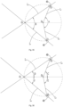
- the two eccentric portions 11 of the crankshaft 10 serve as a first connecting rod L 1 and a second connecting rod L 2 respectively.
- the two limiting channels 31 of the cross groove structure 30 serve as a third connecting rod L 3 and a fourth connecting rod L 4 respectively. Lengths of the first connecting rod L 1 and the second connecting rod L 2 are equal (please refer to Fig. 35 ).
- a first included angle A is formed between the first connecting rod L 1 and the second connecting rod L 2 .
- a second included angle B is formed between the third connecting rod L 3 and the fourth connecting rod L 4 .
- the first included angle A is twice of the second included angle B.
- a connecting line between the axis O 0 of the crankshaft 10 and the axis O 1 of the cross groove structure 30 is a connecting line O 0 O 1 .
- a third included angle C is formed between the first connecting rod L 1 and the connecting line O 0 O 1 .
- a fourth included angle D is formed between the third connecting rod L 3 and the connecting line O 0 O 1 .
- the third included angle C is twice of the fourth included angle D.
- a fifth included angle E is formed between the second connecting rod L 2 and the connecting line O 0 O 1 .
- a sixth included angle F is formed between the fourth connecting rod L 4 and the connecting line O 0 O 1 .
- the fifth included angle E is twice of the sixth included angle F.
- a sum of the third included angle C and the fifth included angle E is the first included angle A
- a sum of the fourth included angle D and the sixth included angle F is the second included angle B.
- the operation method further includes that a rotation angular velocity of the slide blocks 40 relative to the eccentric portions 11 is the same as a revolution angular velocity of the slide blocks 40 around the axis O 0 of the crankshaft 10, and a revolution angular velocity of the cross groove structure 30 around the axis O 0 of the crankshaft 10 is the same as the rotation angular velocity of the slide blocks 40 relative to the eccentric portions 11.
- the axis O 0 of the crankshaft 10 corresponds to a rotation center of the first connecting rod L 1 and the second connecting rod L 2
- the axis O 1 of the cross groove structure 30 corresponds to a rotation center of the third connecting rod L 3 and the fourth connecting rod L 4
- the two eccentric portions 11 of the crankshaft 10 serve as the first connecting rod L 1 and the second connecting rod L 2 respectively
- the two limiting channels 31 of the cross groove structure 30 serve as the third connecting rod L 3 and the fourth connecting rod L 4 respectively.
- the lengths of the first connecting rod L 1 and the second connecting rod L 2 are equal.
- the eccentric portions 11 on the crankshaft 10 drive the corresponding slide blocks 40 to revolve around the axis O 0 of the crankshaft 10, and meanwhile, the slide blocks 40 can rotate relative to the eccentric portions 11 and have a same relative rotation speed. Since the first slide block 40 and the second slide block 40 reciprocate in the two corresponding limiting channels 31 respectively and drive the cross groove structure 30 to move circularly, the motion directions of the two slide blocks 40 always have a phase difference of the second included angle B due to limitation of the two limiting channels 31 of the cross groove structure 30.
- the eccentric portion 11 for driving the other slide block 40 When one of the two slide blocks 40 is at the dead center position, the eccentric portion 11 for driving the other slide block 40 has the largest driving torque, and the eccentric portion 11 with the largest driving torque can normally drive the corresponding slide block 40 to rotate, such that the slide block 40 drives the cross groove structure 30 to rotate, and further drives the slide block 40 at the dead point position to continue rotating through the cross groove structure 30. Therefore, stable operation of the fluid machine is achieved, the dead point position of the motion mechanism is avoided, motion reliability of the fluid machine is improved, and operation reliability of the heat exchange apparatus is guaranteed.
- a maximum moment arm of the driving torque of the eccentric portion 11 is 2e.
- a motion track of the slide block 40 is a circle, and the circle has the axis O 0 of the crankshaft 10 as a center and the line O 0 O 1 as a radius.
- crankshaft 10 rotates twice to complete four suction and exhaust processes.
- the present application provides a fluid machine, and a heat exchange apparatus.
- the heat exchange apparatus includes a fluid machine.
- the fluid machine is the fluid machine described above and described below.
- a fluid machine further includes a flange 50.
- the flange 50 is arranged at an axial end of a cylinder sleeve 20.
- a crankshaft 10 and the flange 50 are concentrically arranged.
- a cross groove structure 30 and the cylinder sleeve 20 are coaxially arranged. Assembly eccentricity of the crankshaft 10 and the cross groove structure 30 is determined by a relative positional relation between the flange 50 and the cylinder sleeve 20.
- the flange 50 is fixed on the cylinder sleeve 20 by means of a fastener.
- Relative positions of an axis of the flange 50 and an axis of an inner ring of the cylinder sleeve 20 is controlled by centering of the flange 50.
- the relative positions of the axis of the flange 50 and the axis of the inner ring of the cylinder sleeve 20 determines relative positions of an axis of the crankshaft 10 and an axis of the cross groove structure 30.
- the essence of centering of the flange 50 is to make eccentricity of an eccentric portion 11 equal to assembly eccentricity of the crankshaft 10 and the cylinder sleeve 20.
- the eccentricity of the two eccentric portions 11 are equal to e.
- assembly eccentricity between the crankshaft 10 and the cylinder sleeve 20 is e (since the cross groove structure 30 and the cylinder sleeve 20 are coaxially arranged, the assembly eccentricity between the crankshaft 10 and the cross groove structure 30 is the assembly eccentricity between the crankshaft 10 and the cylinder sleeve 20).
- the flange 50 includes an upper flange 52 and a lower flange 53.
- a distance between an inner ring axis of the cylinder sleeve 20 and an inner ring axis of the lower flange 53 is e, that is, equal to the eccentricity of the eccentric portions 11.
- a first assembly clearance is provided between the crankshaft 10 and the flange 50, and the first assembly clearance has a range of 0.005 mm-0.05 mm.
- the first assembly clearance has a range of 0.01 mm-0.03 mm.
- two slide blocks 40 are arranged concentric with the two eccentric portions 11 respectively.
- the slide blocks 40 move circularly around the axis of the crankshaft 10.
- a first rotation gap is provided between a wall of a through hole 41 and the eccentric portions 11.
- the first rotation gap has a range of 0.005 mm-0.05 mm.
- a second rotation gap is provided between an outer peripheral surface of the cross groove structure 30 and an inner wall surface of the cylinder sleeve 20.
- the second rotation gap has a size of 0.005 mm-0.1 mm.
- a shaft portion 12 of the crankshaft 10 is integrally formed, and the shaft portion 12 has only one axis. In this way, one-step forming of the shaft portion 12 is facilitated, so as to reduce difficulty in manufacturing the shaft portion 12.
- the shaft portion 12 of the crankshaft 10 includes a first section and a second section connected in an axial direction of the shaft portion.
- the first section and the second section are coaxially arranged.
- the two eccentric portions 11 are arranged on the first section and the second section respectively.
- the first section is detachably connected to the second section. In this way, ease of assembly and disassembly of the crankshaft 10 is guaranteed.
- the shaft portion 12 of the crankshaft 10 and the eccentric portions 11 are integrally formed.
- one-step forming of the crankshaft 10 is facilitated, so as to reduce difficulty in manufacturing the crankshaft 10.
- the shaft portion 12 of the crankshaft 10 is detachably connected to the eccentric portions 11. In this way, installation and disassembly of the eccentric portions 11 are facilitated.
- two ends of the limiting channel 31 penetrate to an outer peripheral surface of the cross groove structure 30.
- difficulty in manufacturing the cross groove structure 30 can be reduced.
- the first included angle A is 160°-200°
- the second included angle B is 80°-100°, as long as a relation that the first included angle A is twice of the second included angle B.
- the first included angle A is 160°
- the second included angle B is 80°
- the first included angle A is 165°
- the second included angle B is 82.5°
- the first included angle A is 170°
- the second included angle B is 85°
- the first included angle A is 175°
- the second included angle B is 87.5°
- the first included angle A is 180°
- the second included angle B is 90°
- the first included angle A is 185°
- the second included angle B is 92.5°
- the first included angle A is 190°, and the second included angle B is 95°.
- the first included angle A is 195°
- the second included angle B is 97.5°
- each eccentric portion 11 has a circular arc surface.
- a central angle of the circular arc surface is 180° or above. In this way, it is guaranteed that the circular arc surfaces of the eccentric portions 11 can apply an effective drive force to the slide blocks 40, such that reliability of movement of the slide blocks 40 can be guaranteed.
- each eccentric portion 11 has a cylindrical shape.
- a proximal end of the eccentric portion 11 is flush with an outer circle of the shaft portion 12 of the crankshaft 10.
- the proximal end of the eccentric portion 11 protrudes beyond the outer circle of the shaft portion 12 of the crankshaft 10.
- the proximal end of the eccentric portion 11 is located on an inner side of the outer circle of the shaft portion 12 of the crankshaft 10.
- the slide blocks 40 include a plurality of sub-structures, and the plurality of sub-structures are spliced to define through holes 41.
- the two eccentric portions 11 are spaced in the axial direction of the crankshaft 10. In this way, in a process of assembling the crankshaft 10, the cylinder sleeve 20 and the two slide blocks 40, it is guaranteed that a separation distance between the two eccentric portions 11 can provide an assembly space for the cylinder sleeve 20, so as to guarantee convenience of assembly.
- the cross groove structure 30 has a central hole 32.
- the two limiting channels 31 are in communication through the central hole 32.
- a diameter of the central hole 32 is greater than that of the shaft portion 12 of the crankshaft 10. In this way, it is guaranteed that the crankshaft 10 can smoothly pass through the central hole 32.
- the diameter of the central hole 32 is greater than that of the eccentric portions 11. In this way, it is guaranteed that the eccentric portions 11 of the crankshaft 10 can smoothly pass through the central hole 32.
- an axial projection of each slide block 40 in the through hole 41 has two relatively parallel straight line segments and an arc segment connecting ends of the two straight line segments.
- the limiting channels 31 have a set of first slide surfaces arranged oppositely and making slide contact with the slide blocks 40.
- the slide blocks 40 have second slide surfaces matching the first slide surfaces.
- the slide blocks 40 have pressing surfaces 42 facing ends of the limiting channels 31.
- the pressing surfaces 42 serve as heads of the slide blocks 40.
- the two second slide surfaces are connected by the pressing surfaces 42.
- the pressing surfaces 42 face a volume-variable cavity 311.
- the pressing surfaces 42 are arc surfaces.
- a distance between arc centers of the arc surfaces and centers of the through holes 41 is equal to the eccentricity of the eccentric portions 11.
- the center of the through holes 41 of the slide blocks 40 is O slide block
- the distance between the arc center of each of the two arc surfaces and the center of the through holes 41 is e, that is, the eccentricity of the eccentric portions 11.
- Dotted lines X in Fig. 9 indicate circles in which the arc centers of the two arc surfaces are located.
- a radius of curvature of the arc surfaces is equal to a radius of the inner circle of the cylinder sleeve 20.
- the radius of curvature of the arc surfaces has a difference value from the radius of the inner circle of the cylinder sleeve 20 in a range of -0.05 mm-0.025 mm.
- the difference value has a range of -0.02 mm-0.02 mm.
- a projected area S slide block of each pressing surface 42 in the slide direction of the slide block 40 and an area S exhaust of a compression exhaust port 22 of the cylinder sleeve 20 satisfy a condition that a value of S slide block /S exhaust is 8-25.
- the value of S slide block /S exhaust is 12-18.
- the fluid machine shown in the example is a compressor.
- the compressor includes a liquid separator component 80, a housing assembly 81, a motor assembly 82, a pump assembly 83, an upper cover assembly 84 and a lower cover assembly 85.
- the liquid separator component 80 is arranged outside the housing assembly 81.
- the upper cover assembly 84 is assembled at an upper end of the housing assembly 81.
- the lower cover assembly 85 is assembled at a lower end of the housing assembly 81.
- Both the motor assembly 82 and the pump assembly 83 are located inside the housing assembly 81.
- the motor assembly 82 is located above the pump assembly 83, and alternatively, the motor assembly 82 is located below the pump assembly 83.
- the pump assembly 83 of the compressor includes the crankshaft 10, the cylinder sleeve 20, the cross groove structure 30, the slide blocks 40, the upper flange 52 and the lower flange 53 described above.
- the components are connected by welding, shrink fitting, or cold pressing.
- An assembly process of the entire pump assembly 83 is as follows: the lower flange 53 is fixed on the cylinder sleeve 20, the two slide blocks 40 are arranged in the corresponding two limiting channels 31 respectively, the two eccentric portions 11 of the crankshaft 10 extend into the two through holes 41 of the corresponding two slide blocks 40 respectively, then the crankshaft 10, the cross groove structure 30 and the two slide blocks 40 that are assembled are arranged in the cylinder sleeve 20, one end of the crankshaft 10 is installed on the lower flange 53, and the other end of the crankshaft 10 penetrates the upper flange 52, as shown in Figs. 2 and 3 for details.
- variable volume cavities 311 enclosed spaces defined by the slide blocks 40, the limiting channels 31, the cylinder sleeve 20 and the upper flange 52(or the lower flange 53) are the variable volume cavities 311.
- the pump assembly 83 has four variable volume cavities 311 in total. During rotation of the crankshaft 10, the crankshaft 10 rotates twice, and a single volume-variable cavity 311 completes one suction and exhaust process. For the compressor, the crankshaft 10 rotates twice, and four suction and exhaust processes are completed in total.
- variable volume cavities 311 are the enclosed spaces defined by the pressing surfaces 42 of the heads of the slide blocks 40, two side wall surfaces and bottom surfaces of the limiting channels 31, a part of an inner wall surface of the cylinder sleeve 20, and a part of a surface of the upper flange 52 facing the cylinder sleeve 20 (or a part of a surface of the lower flange 53 facing the cylinder sleeve 20).
- variable volume cavities 311 increase when the slide blocks 40 rotate clockwise from 0° to 180°.
- the variable volume cavities 311 are in communication with a suction cavity 23 of the cylinder sleeve 20.
- a volume of the variable volume cavities 311 reaches a maximum value.
- the variable volume cavities 311 are separated from the suction cavity 23, such that suction operation is completed.
- the slide blocks 40 continue to rotate clockwise from 180° to 360°, and the variable volume cavities 311 are reduced.
- the slide blocks 40 compress air in the variable volume cavities 311.
- an exhaust valve plate 61 of an exhaust valve assembly 60 is opened to start exhaust operation. After compression is completed, a next cycle is started.
- a point marked with M is taken as a reference point of relative motion of the slide blocks 40 and the crankshaft 10.
- Fig. 11 shows a process of clockwise rotation of the slide blocks 40 from 0° to 180°, an angle of rotation of the slide blocks 40 is ⁇ 1, and a corresponding angle of rotation of the crankshaft 10 is 2 ⁇ 1.
- Fig. 13 shows a process of continuous clockwise rotation of the slide blocks 40 from 180° to 360°, an angle of rotation of the slide blocks 40 is 180° + ⁇ 2, and a corresponding angle of rotation of the crankshaft 10 is 360° + 2 ⁇ 2.
- variable volume cavities 311 are in communication with the compression exhaust port 22, an angle of rotation of the slide blocks 40 is 180° + ⁇ 3, and a corresponding angle of rotation of the crankshaft 10 is 360° + 2 ⁇ 3, that is, one rotation of the slide blocks 40 corresponds to two rotations of the crankshaft 10, where ⁇ 1 ⁇ ⁇ 2 ⁇ ⁇ 3.
- the motor assembly 82 drives the crankshaft 10 to rotate.
- the two eccentric portions 11 of the crankshaft 10 drive the corresponding two slide blocks 40 to move respectively.
- the slide blocks 40 revolve around the axis of the crankshaft 10, the slide blocks 40 rotate relative to the eccentric portions 11.
- the slide blocks 40 reciprocate along the limiting channels 31, and drive the cross groove structure 30 to rotate in the cylinder sleeve 20.
- the slide blocks 40 reciprocate along the limiting channels 31 while revolving, thereby constituting a motion mode of the cross slide block mechanism.
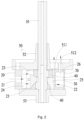
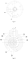
- the present application combines exhaust at an end surface of the flange 50 and exhaust at a side of the cylinder sleeve 20 to reduce the exhaust loss of the compressor, specifically as follows: As shown in Figs. 1-27 , at least one flange 50 of the two flanges 50 is provided with a first axial exhaust hole 511, and at least one flange 50 of the two flanges 50 is provided with a second axial exhaust hole 512.
- An inclined notch 27 is provided at an edge of an inner circle of at least one of the two axial ends of the cylinder sleeve 20. The inclined notch 27 is in communication with the first axial exhaust hole 511.
- At least one exhaust port 22 is provided on a side wall surface of the cylinder sleeve 20. The exhaust port 22 is in communication with the second axial exhaust hole 512.
- At least one flange 50 of the two flanges 50 is provided with the first axial exhaust hole 511, and at least one flange 50 of the two flanges 50 is provided with the second axial exhaust hole 512.
- the inclined notch 27 is provided at the edge of the inner circle of at least one of the two axial ends of the cylinder sleeve 20. The inclined notch 27 is in communication with the first axial exhaust hole 511.
- At least one exhaust port 22 is provided on the side wall surface of the cylinder sleeve 20. The exhaust port 22 is in communication with the second axial exhaust hole 512. In this way, exhaust reliability of the fluid machine is guaranteed, such that the exhaust loss of the fluid machine is reduced, and efficiency of the fluid machine is improved.
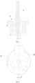
- the first axial exhaust hole 511 and the second axial exhaust hole 512 in the same flange 50 are on a same radius of the flange 50.
- the second axial exhaust hole 512 is located on an outer peripheral side of the first axial exhaust hole 511. In this way, throttle loss is reduced advantageously, thereby improving performance of the compressor. Moreover, design difficulty and manufacturing difficulty of the flanges 50 are reduced. It is easy to find out a reason and analyze it when an abnormal situation occurs later.
- the flange 50 at one end of the cylinder sleeve 20 having the inclined notch 27 is provided with the first axial exhaust hole 511, and the inclined notch 27 is arranged opposite the first axial exhaust hole 511.
- exhaust reliability of the variable volume cavities 311 in communication with the inclined notch 27 is guaranteed.
- a geometric center line of the first axial exhaust hole 511 passes through a geometric center of the inclined notch 27. In this way, exhaust loss is reduced advantageously, thereby guaranteeing that the efficiency of the compressor can be optimized.
- a projection of each slide block 40 in a slide direction of the slide block is a part of a semicircle.
- an axial projection of each slide block 40 in the through hole 41 has two relatively parallel straight line segments and an arc segment connecting ends of the two straight line segments.
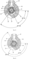
- the exhaust port 22 is arranged at a position in an angle range of (arccos (2R/B) - 2 * arccos 2R/B) in a circumferential direction of the cylinder sleeve 20.
- R is a radius of an inner circle of the cylinder sleeve 20
- B is a distance between the two relatively parallel straight line segments of the axial projection of the slide block 40 in the through hole 41.
- the angle range of ⁇ in Fig. 17 is (arccos (2R/B) - 2 * arccos 2R/B), that is, the exhaust port 22 can be arranged within the above range in the circumferential direction of the cylinder sleeve 20.
- an exhaust cavity 25 is provided in an outer wall of the cylinder sleeve 20.
- the exhaust port 22 is in communication with the exhaust cavity 25 from an inner wall of the cylinder sleeve 20.
- the fluid machine further includes an exhaust valve assembly, and the exhaust valve assembly is arranged in the exhaust cavity 25 and corresponds to the exhaust port 22.
- the exhaust cavity 25 is configured to accommodate the exhaust valve assembly, so as to effectively reduce an occupied space of the exhaust valve assembly, such that the components are reasonably arranged, and a space utilization rate of the cylinder sleeve 20 is improved.
- a communication hole 26 is further provided in an axial end surface of the cylinder sleeve 20.
- the communication hole 26 is in communication with the exhaust cavity 25.
- the communication hole 26 is in communication with the second axial exhaust hole 512. In this way, exhaust reliability of the cylinder sleeve 20 is guaranteed.
- the fluid machine further includes an exhaust cover plate 70.
- the exhaust cover plate 70 is connected to the cylinder sleeve 20 and seals the exhaust cavity 25.
- the exhaust cover plate 70 isolates the variable volume cavities 311 from an outer space of the pump assembly 83.
- the exhaust cover plate 70 is fixed on the cylinder sleeve 20 by means of a fastener.
- the fastener is a screw.
- an outer contour of exhaust cover plate 70 is adapted to an outer contour of exhaust cavity 25.
- a distance between a plane where one end of the exhaust port 22 in communication with the exhaust cavity 25 and an axis of the cylinder sleeve 20 is K
- a radius of an inner circle of the cylinder sleeve 20 is R
- 1 mm ⁇ K - R ⁇ 5 mm is 1 mm.
- a cavity sectional area of the exhaust cavity 25 in an axial direction of the cylinder sleeve 20 is S3, a height of the exhaust cavity 25 in the axial direction of the cylinder sleeve 20 is N, a displacement of the fluid machine is V, and 0.2 ⁇ (N * S3)/V ⁇ 5.
- S3 is in square millimeters, and N is in mm.
- an exhaust cavity 25 is provided in an outer wall of the cylinder sleeve 20.
- a boss structure 29 is arranged on a cavity wall surface of the exhaust cavity 25.
- the exhaust port 22 penetrates from an inner wall of the cylinder sleeve 20 to the boss structure 29 and is in communication with the exhaust cavity 25.
- the boss structure 29 is in a form of an outward convex structure.
- the arrangement of the boss structure 29 advantageously reduces an opening loss of the exhaust valve plate of the exhaust valve assembly caused by viscosity of lubricating oil.
- a thickness of the boss structure 29 in an extension direction of the exhaust port 22 is M, and 0.05 mm ⁇ M ⁇ 3 mm.
- the thickness of the cylinder sleeve wall at the exhaust port 22 is increased to guarantee sufficient strength of the cylinder sleeve wall at the exhaust port.
- the opening loss of the exhaust valve plate of the exhaust valve assembly can be reduced.
- a sectional area of a cross section of each slide block 40 in a sliding direction of the slide block is S.
- the assembly eccentricity of the cross groove structure 30 is e.
- an area of a hole section of the exhaust port 22 is S1
- a volume of the single volume-variable cavity 311 is V1
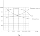
- 750 ⁇ V1/S1 ⁇ 3300 is provided.
- Coefficient of performance (COP) in Fig. 41 refers to a ratio of a cooling capacity or heating capacity of the compressor to power consumption of the compressor, and is a parameter reflecting performance and energy saving of the compressor.
- the value range of the ratio V1/S1 is a ratio of numerical values without units.
- a longitudinal section of the inclined notch 27 through a diameter of the cylinder sleeve 20 coincides with a longitudinal section of the exhaust port 22 through the diameter of the cylinder sleeve 20.
- the inclined notch 27 is arranged at a position in an angle range of (arccos (2R/B) - 2 * arccos 2R/B) in a circumferential direction of the cylinder sleeve 20.
- R is a radius of an inner circle of the cylinder sleeve 20
- B is a distance between the two relatively parallel straight line segments of the axial projection of the slide block 40 in the through hole 41.
- the angle range of ⁇ in Fig. 19 is (arccos (2R/B) - 2 * arccos 2R/B), that is, the inclined notch 27 can be arranged within the above range in the circumferential direction of the cylinder sleeve 20.
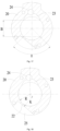
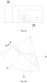
- an inclined direction of the inclined notch 27 extends from an end surface of one axial end of the cylinder sleeve 20 to an axis of the cylinder sleeve 20, an included angle between the inclined notch 27 and the end surface of the cylinder sleeve 20 is ⁇ , and 15° ⁇ ⁇ ⁇ 60°.
- the inclined notch 27 can guide air flow.
- the inclined notch 27 increases a clearance of the compressor, and then the performance of the compressor is reduced. Since air encounters resistance and loss when flowing, the included angle ⁇ between the inclined notch 27 and the end surface of the cylinder sleeve 20 can be reasonably optimized to find an optimal point between an air flow loss and increasing the clearance.
- an equivalent diameter of a circle in which the inclined notch 27 is located is D
- a volume of the single volume-variable cavity 311 is V1
- 400 ⁇ V1/D ⁇ 1000 is V1
- the unit of D is mm.
- V1/D can satisfy: 400 ⁇ V1/D ⁇ 1000.
- An optimal point is found between reducing the air flow loss and increasing the clearance.
- the value range of the ratio V1/ D is a ratio of numerical values without units.
- an area of a hole section of the first axial exhaust port 22 is S4, a volume of the single volume-variable cavity 311 is V1, and 750 ⁇ V1/S4 ⁇ 3300.
- a balance between the exhaust loss and the clearance volume is taken into account to guarantee that the COP of the compressor can be optimized.
- the value range of the ratio V1/S4 is a ratio of numerical values without units.
- an area of a hole section of the second axial exhaust port 22 is S2
- a volume of the single volume-variable cavity 311 is V1
- 50 ⁇ V1/S2 ⁇ 250 is taken into account to guarantee that the COP of the compressor can be optimized.
- the value range of the ratio V1/S2 is a ratio of numerical values without units.
- the cylinder sleeve 20 has one radial suction hole 21 and a suction cavity 23.
- the suction cavity 23 is in communication with the radial suction hole 21. In this way, it is guaranteed that a large amount of air can be stored in the suction cavity 23, such that the variable volume cavities 311 can fully suck the air, and then the compressor can suck enough air. When air suction is insufficient, the stored air can be supplied to the variable volume cavities 311 in time, so as to guarantee compression efficiency of the compressor.
- the suction cavity 23 is a cavity formed by radially hollowing out the inner wall surface of the cylinder sleeve 20.
- One suction cavity 23 may be provided, and alternatively, two suction cavities with one above the other may also be provided.
- the suction cavity 23 extends by a first preset distance around the circumferential direction of the inner wall surface of the cylinder sleeve 20 to form an arc suction cavity 23. In this way, it is guaranteed that a volume of the suction cavity 23 is large enough to store a large amount of air.
- two suction cavities 23 are provided.
- the two suction cavities 23 are spaced in the axial direction of the cylinder sleeve 20.
- the cylinder sleeve 20 further has a suction communication cavity 24.
- the two suction cavities 23 are in communication with the suction communication cavity 24, and the radial suction hole 21 is in communication with the suction cavities 23 through the suction communication cavity 24.
- the volume of the suction cavities 23 can be increased, and suction pressure pulsation is reduced.
- the suction communication cavity 24 extends by a second preset distance in the axial direction of the cylinder sleeve 20. At least one end of the suction communication cavity 24 penetrates the axial end surface of the cylinder sleeve 20. In this way, it is convenient to form the suction communication cavity 24 from the end surface of the cylinder sleeve 20, and machining convenience of the suction communication cavity 24 is guaranteed.
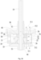
- an exhaust port 22 is provided in a side wall of the cylinder sleeve 20 close to the lower flange 53, an inclined notch 27 is formed on an inner circle of an end of the cylinder sleeve 20 facing the upper flange 52, and moreover, the upper flange 52 is provided with a first axial exhaust hole 511 and a second axial exhaust hole 512.
- the exhaust port 22 is in communication with the second axial exhaust hole 512 through the exhaust cavity 25 and the communication hole 26.
- the inclined notch 27 is in communication with the first axial exhaust hole 511.
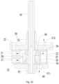
- an exhaust port 22 is provided in a side wall of a cylinder sleeve 20 close to an upper flange 52, an inclined notch 27 is formed on an inner circle of an end of the cylinder sleeve 20 facing an lower flange 53, moreover, the lower flange 53 is provided with a first axial exhaust hole 511, and the upper flange 52 is provided with a second axial exhaust hole 512.
- the exhaust port 22 is in communication with the second axial exhaust hole 512 through an exhaust cavity 25 and a communication hole 26.
- the inclined notch 27 is in communication with the first axial exhaust hole 511.
- an exhaust port 22 is provided in a side wall of a cylinder sleeve 20 close to an upper flange 52, an inclined notch 27 is formed on an inner circle of an end of the cylinder sleeve 20 facing an lower flange 53, and moreover, the lower flange 53 is provided with a first axial exhaust hole 511 and a second axial exhaust hole 512.
- the exhaust port 22 is in communication with the second axial exhaust hole 512 through an exhaust cavity 25 and a communication hole 26.
- the inclined notch 27 is in communication with the first axial exhaust hole 511.
- an exhaust port 22 is provided in a side wall of a cylinder sleeve 20 close to an upper flange 52
- an inclined notch 27 is formed on an inner circle of an end of the cylinder sleeve 20 facing the upper flange 52
- an exhaust port 22 is provided in a side wall of the cylinder sleeve 20 close to the lower flange 53
- an inclined notch 27 is formed on an inner circle of an end of the cylinder sleeve 20 facing the lower flange 53
- the upper flange 52 and the lower flange 53 are each provided with a first axial exhaust hole 511 and a second axial exhaust hole 512.
- the exhaust port 22 on an upper side of the cylinder sleeve 20 is in communication with the second axial exhaust hole 512 on the upper flange 52 through an exhaust cavity 25 and a communication hole 26, and the inclined notch 27 on an upper end surface of the cylinder sleeve 20 is in communication with the first axial exhaust hole 511 on the upper flange 52.
- the exhaust port 22 on a lower side of the cylinder sleeve 20 is in communication with the second axial exhaust hole 512 on the lower flange 53 through the exhaust chamber 25 and the communication hole 26, and the inclined notch 27 on a lower end surface of the cylinder sleeve 20 is in communication with the first axial exhaust hole 511 on the lower flange 53.
- a cylinder sleeve 20 has two radial suction holes 21, the two radial suction holes 21 are spaced in an axial direction of the cylinder sleeve 20, and the two radial suction holes 21 are respectively in communication with suction cavities 23 at corresponding sides.
- a cylinder sleeve 20 has two radial suction holes 21, the two radial suction holes 21 are spaced in an axial direction of the cylinder sleeve 20, and the two radial suction holes 21 are respectively in communication with suction cavities 23 at corresponding sides.
- a cylinder sleeve 20 has two radial suction holes 21, the two radial suction holes 21 are spaced in an axial direction of the cylinder sleeve 20, and the two radial suction holes 21 are respectively in communication with suction cavities 23 at corresponding sides.
- a cylinder sleeve 20 has two radial suction holes 21, the two radial suction holes 21 are spaced in an axial direction of the cylinder sleeve 20, and the two radial suction holes 21 are respectively in communication with suction cavities 23 at corresponding sides.
- suction may be performed by means of the flanges 50, specifically, the upper flange 52 and the lower flange 53.
- one flange 50 of the two flanges 50 may be used for suction in combination with the cylinder sleeve 20.
- the spatially-relative terms such as “on”, “above”, “on the upper surface”, and “on the upper portion” can be used herein to describe the spatial position relation between one device or feature and another device or feature as shown in the figures. It should be understood that the spatially-relative terms are intended to encompass different orientations in use or operation except for the orientation of the device described in the figures. For example, if the device in the accompanying drawings is inverted, a device described as “above another device or configuration” or “on another device or configuration” will then be located as “below another device or configuration” or “underneath another device or configuration”. Therefore, the illustrative term “above” can indicate two orientations “above” and "below". The device can also be located in other different ways (being rotated by 90 degrees or in another orientation), and the spatially-relative descriptions used herein are interpreted correspondingly.
Landscapes
- Engineering & Computer Science (AREA)
- Mechanical Engineering (AREA)
- General Engineering & Computer Science (AREA)
- Applications Or Details Of Rotary Compressors (AREA)
- Compressors, Vaccum Pumps And Other Relevant Systems (AREA)
Abstract
Description
- The present invention claims the priority to
Chinese Patent Application No. 202210565477.9, filed on May 23, 2022 - The present invention relates to the technical field of heat exchange systems, in particular to a fluid machine and a heat exchange apparatus.
- A fluid machine in the related art includes a compressor, an expander, etc, and includes the compressor herein, for example.
- The air-conditioning industry has been oriented towards high efficiency and low noise as per the national energy conservation and environment protection policy and the requirements of consumers for air-conditioning comfort. The compressor, the heart of an air conditioner, has a direct impact on the energy efficiency and noise level of the air conditioner. A rolling rotor compressor, the prevailing household air-conditioning compressor, has been fairly mature after nearly a century of development, with limited optimization space due to its structural principle.
- A main objective of the invention is to provide a fluid machine and a heat exchange apparatus. According to an aspect of the present invention, a fluid machine is provided. The fluid machine includes a crankshaft, a cylinder sleeve, a cross groove structure, slide blocks, and two flanges. The crankshaft is provided with two eccentric portions in an axial direction of the crankshaft. The crankshaft and the cylinder sleeve are arranged in an eccentric manner with a fixed eccentric distance. The cross groove structure is rotatably arranged in the cylinder sleeve, the cross groove structure has two limiting channels, the two limiting channels are sequentially arranged in the axial direction of the crankshaft, and an extension direction of the limiting channels is perpendicular to the axial direction of the crankshaft. The slide blocks has through holes, two slide blocks are provided, the two eccentric portions correspondingly extend into the two through holes of the two slide blocks, the two slide blocks are correspondingly slidably arranged in the two limiting channels to form a volume-variable cavity, the volume-variable cavity is located in a slide direction of the slide blocks, and the crankshaft rotates to drive the slide blocks to interact with the cross groove structure while reciprocating in the limiting channels in a sliding manner, such that the cross groove structure and the slide blocks rotate in the cylinder sleeve. The two flanges are arranged at two axial ends of the cylinder sleeve respectively, at least one flange of the two flanges is provided with a first axial exhaust hole, and at least one flange of the two flanges is provided with a second axial exhaust hole. An inclined notch is provided at an edge of an inner circle of at least one of the two axial ends of the cylinder sleeve, the inclined notch is in communication with the first axial exhaust hole, at least one exhaust port is provided on a side wall surface of the cylinder sleeve, and the exhaust port is in communication with the second axial exhaust hole.
- In some embodiments, the first axial exhaust hole and the second axial exhaust hole in the same flange are on a same radius of the flange, and the second axial exhaust hole is located on an outer peripheral side of the first axial exhaust hole.
- In some embodiments, the flange at one end of the cylinder sleeve having the inclined notch is provided with the first axial exhaust hole, and the inclined notch is arranged opposite the first axial exhaust hole.
- In some embodiments, a geometric center line of the first axial exhaust hole passes through a geometric center of the inclined notch.
- In some embodiments, a projection of each slide block in a slide direction of the slide block is a part of a semicircle; and/or, an axial projection of each slide block in the through hole has two relatively parallel straight line segments and an arc segment connecting ends of the two straight line segments, and the exhaust port is arranged at a position in an angle range of (arccos (2R/B) - 2 * arccos (2R/B)) in a circumferential direction of the cylinder sleeve, where R is a radius of an inner circle of the cylinder sleeve, and B is a distance between the two relatively parallel straight line segments of the axial projection of the slide block in the through hole.
- In some embodiments, an exhaust cavity is provided in an outer wall of the cylinder sleeve, the exhaust port is in communication with the exhaust cavity from an inner wall of the cylinder sleeve, the fluid machine further includes an exhaust valve assembly, and the exhaust valve assembly is arranged in the exhaust cavity and corresponds to the exhaust port. A communication hole is further provided in an axial end surface of the cylinder sleeve, the communication hole is in communication with the exhaust cavity, and the communication hole is in communication with the second axial exhaust hole.
- In some embodiments, a distance between a plane where one end of the exhaust port in communication with the exhaust cavity and an axis of the cylinder sleeve is K, a radius of an inner circle of the cylinder sleeve is R, and 1 mm ≤ K - R ≤ 5 mm.
- In some embodiments, a cavity sectional area of the exhaust cavity in an axial direction of the cylinder sleeve is S3, a height of the exhaust cavity in the axial direction of the cylinder sleeve is N, a displacement of the fluid machine is V, and 0.2 ≤ (N * S3)/V ≤ 5.
- In some embodiments, an exhaust cavity is provided in an outer wall of the cylinder sleeve, a boss structure is arranged on a cavity wall surface of the exhaust cavity, and the exhaust port penetrates from an inner wall of the cylinder sleeve to the boss structure and is in communication with the exhaust cavity.
- In some embodiments, a thickness of the boss structure in an extension direction of the exhaust port is M, and 0.05 mm ≤ M ≤ 3 mm.
- In some embodiments, an area of a hole section of the exhaust port is S1, a volume of the single volume-variable cavity is V1, and 750 ≤ V1/S1 ≤ 3300.
- In some embodiments, an inclined direction of the inclined notch extends from an end surface of one axial end of the cylinder sleeve to an axis of the cylinder sleeve, an included angle between the inclined notch and the end surface of the cylinder sleeve is α, and 15° ≤ α ≤ 60°.
- In some embodiments, an equivalent diameter of a circle in which the inclined notch is located is D, a volume of the single volume-variable cavity is V1, and 400 ≤ V1/D ≤ 1000.
- In some embodiments, a longitudinal section of the inclined notch through a diameter of the cylinder sleeve coincides with a longitudinal section of the exhaust port through the diameter of the cylinder sleeve.
- In some embodiments, an area of a hole section of the first axial exhaust port is S4, a volume of the single volume-variable cavity is V1, and 750 ≤ V1/S4 ≤ 3300; and/or an area of a hole section of the second axial exhaust port is S2, a volume of the single volume-variable cavity is V1, and 50 ≤ V1/S2 ≤ 250.
- In some embodiments, the exhaust cavity penetrates to an outer wall surface of the cylinder sleeve, the fluid machine further includes an exhaust cover plate, and the exhaust cover plate is connected to the cylinder sleeve and seals the exhaust cavity.
- In some embodiments, a phase difference of a first included angle A exists between the two eccentric portions, eccentric amounts of the two eccentric portions are equal, a phase difference of a second included angle B exists between the extension directions of the two limiting channels, and the first angle A is twice of the second angle B.
- In some embodiments, the first included angle A is 160°-200°, and the second included angle B is 80°-100°.
- In some embodiments, each slide block has a pressing surface, facing an end of the limiting channel, and a projected area Sslide block of the pressing surface in the slide direction of the slide block and an area Sexhaust of the exhaust port of the cylinder sleeve satisfy that a value of Sslide block/Sexhaust is 8-25.
- According to the other aspect of the present invention, a heat exchange apparatus is provided. The heat exchange apparatus includes a fluid machine. The fluid machine is the above fluid machine.
- In order to more clearly illustrate technical solutions in the examples of the present application or in the traditional art, a brief introduction to the accompanying drawings required for the description of the examples or the prior art will be provided below. Apparently, the accompanying drawings in the following description are merely the examples of the present application, and those of ordinary skill in the art would also be able to derive other drawings from these disclosed drawings without making creative efforts.
-
Fig. 1 illustrates a schematic diagram of an internal structure of a compressor according to Example 1 of the present application; -
Fig. 2 illustrates a schematic structural diagram of a pump assembly of the compressor inFig. 1 ; -
Fig. 3 illustrates an exploded view of the pump assembly inFig. 2 ; -
Fig. 4 illustrates a schematic structural diagram of assembling of a crankshaft, a cross groove structure and slide blocks inFig. 3 ; -
Fig. 5 illustrates a sectional schematic structural diagram of the crankshaft, the cross groove structure, and the slide blocks inFig. 4 ; -
Fig. 6 illustrates a schematic structural diagram of a shaft portion and eccentricity of two eccentric portions of the crankshaft inFig. 4 ; -
Fig. 7 illustrates a sectional schematic structural diagram of assembly eccentricity of a crankshaft and a cylinder sleeve inFig. 3 ; -
Fig. 8 illustrates a schematic structural diagram of eccentricity between a cylinder sleeve and a lower flange inFig. 3 ; -
Fig. 9 illustrates a schematic structural diagram of moving upwards of slide blocks in an axial direction of a through hole inFig. 3 ; -
Fig. 10 illustrates a schematic structural diagram of a state of the compressor inFig. 3 at the beginning of suction; -
Fig. 11 illustrates a schematic structural diagram of a state of the compressor inFig. 3 in a suction process; -
Fig. 12 illustrates a schematic structural diagram of a state of the compressor inFig. 3 at the end of suction; -
Fig. 13 illustrates a schematic structural diagram of a state of the compressor inFig. 3 during air compression; -
Fig. 14 illustrates a schematic structural diagram of a state of the compressor inFig. 3 in an exhaust process; -
Fig. 15 illustrates a schematic structural diagram of a state of the compressor inFig. 3 at the end of exhaust; -
Fig. 16 illustrates a schematic structural diagram of a cylinder sleeve inFig. 3 ; -
Fig. 17 illustrates a sectional schematic structural diagram of a cylinder sleeve inFig. 3 , in which an angle range of an exhaust port arranged in a circumferential direction of the cylinder sleeve is shown; -
Fig. 18 illustrates a sectional schematic structural diagram of a cylinder sleeve inFig. 3 , in which a schematic diagram of a relation between K and R is shown; -
Fig. 19 illustrates a sectional schematic structural diagram of a cylinder sleeve inFig. 3 , in which an angle range of an inclined notch arranged in a circumferential direction of the cylinder sleeve is shown; -
Fig. 20 illustrates a sectional schematic structural diagram of a cylinder sleeve inFig. 3 from another perspective, in which an included angle between an inclined notch and an end face of the cylinder sleeve is shown; -
Fig. 21 illustrates a schematic structural diagram of an upper flange inFig. 3 from a top view; -
Fig. 22 illustrates a sectional schematic structural diagram of the pump assembly inFig. 2 from another perspective, in which assembly eccentricity between a crankshaft and a cylinder sleeve is e; -
Fig. 23 illustrates a schematic structural diagram of an exhaust cavity side of a cylinder sleeve inFig. 3 ; -
Fig. 24 illustrates a sectional schematic structural diagram of a cylinder sleeve inFig. 2 , in which a cross groove structure, slide blocks and a crankshaft are omitted; -
Fig. 25 illustrates a schematic structural diagram of an exhaust cavity side of a cylinder sleeve according to an optional example of the present application, in which a boss structure is provided at an exhaust port; -
Fig. 26 illustrates a partial sectional schematic structural diagram of the cylinder sleeve ofFig. 25 ; -
Fig. 27 illustrates a schematic structural diagram of a cross section of a slide block inFig. 3 in a slide direction of the slide block; -
Fig. 28 illustrates a schematic structural diagram of a pump assembly according to Example 2 of the present application; -
Fig. 29 illustrates a schematic structural diagram of a pump assembly according to Example 3 of the present application; -
Fig. 30 illustrates a schematic structural diagram of a pump assembly according to Example 4 of the present application; -
Fig. 31 illustrates a schematic structural diagram of a pump assembly according to Example 5 of the present application; -
Fig. 32 illustrates a schematic structural diagram of a pump assembly according to Example 6 of the present application; -
Fig. 33 illustrates a schematic structural diagram of a pump assembly according to Example 7 of the present application; -
Fig. 34 illustrates a schematic structural diagram of a pump assembly according to Example 8 of the present application; -
Fig. 35 illustrates a schematic diagram of a mechanism principle of operation of a compressor according to an optional example of the present application; -
Fig. 36 illustrates a schematic diagram of the mechanism principle of operation of the compressor inFig. 35 ; -
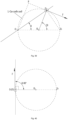
Fig. 37 illustrates a schematic diagram of a mechanism principle of operation of a compressor in the related art; -
Fig. 38 illustrates a schematic diagram of a mechanism principle of operation of a compressor improved in the related art; -
Fig. 39 illustrates a schematic diagram of the mechanism principle of operation of the compressor inFig. 38 , in which a moment arm of a drive shaft driving a slide block to rotate is shown; -
Fig. 40 illustrates a schematic diagram of the mechanism principle of operation the compressor inFig. 38 , in which a center of a limiting groove structure coincides with a center of an eccentric portion; and -
Fig. 41 illustrates a schematic diagram of change curves of an exhaust loss, a coefficient of performance (COP) and a clearance volume of a compressor with V1/S1. - The drawings include the following reference numerals:
10. crankshaft; 11. eccentric portion; 12. shaft portion; 20. cylinder sleeve; 21. radial suction hole; 22. exhaust port; 23. suction cavity; 24. suction communication cavity; 25. exhaust cavity; 26. communication hole; 27. inclined notch; 29. boss structure; 30. cross groove structure; 31. limiting channel; 311. volume-variable cavity; 32. central hole; 40. slide block; 41. through hole; 42. pressing surface; 50, flange; 511. first axial exhaust hole; 512. second axial exhaust hole; 52. upper flange; 53. lower flange; 70. exhaust cover plate; 80. liquid separator component; 81. housing assembly; 82. motor assembly; 83. pump assembly; 84. upper cover assembly; and 85. lower cover assembly. - The technical solutions in examples of the invention are clearly and completely described below with reference to the accompanying drawings in the examples of the invention. Apparently, the examples described are merely some examples rather than all examples of the invention. Based on the examples of the invention, all other examples derived by those of ordinary skill in the art without making creative efforts fall within the scope of protection of the invention.
- In the art known to inventors, as shown in
Fig. 37 , a mechanism principle of operation of a compressor is proposed based on a cross slide block mechanism, that is, a cylinder is eccentrically arranged with respect to a drive shaft with a point O1 as a cylinder center, a point O2 as a drive shaft center, and a point O3 as a slide block center. The slide block center O3 moves circularly on a circle having a diameter of O1O2. - In the above mechanism principle of operation, the cylinder center O1 and the drive shaft center O2 serve as two rotation centers of a motion mechanism. Moreover, a midpoint O0 of a line segment O1O2 serves as a virtual center of the slide block center O3, such that the slide block reciprocates relative to the cylinder and also reciprocates relative to the drive shaft.
- Since the midpoint O0 of the line segment O1O2 is a virtual center, no balance system can be set, resulting in a problem that high frequency vibration characteristics of the compressor are deteriorated. Based on the above mechanism principle of operation, as shown in
Fig. 38 , a motion mechanism with O0 as the drive shaft center is provided, that is, the cylinder center O1 and the drive shaft center O0 serve as two rotation centers of the motion mechanism. The drive shaft has an eccentric portion, the slide block is arranged coaxial with the eccentric portion, and assembly eccentricity of the drive shaft and the cylinder is equal to eccentricity of the eccentric portion, such that the slide block center O3 moves circularly around the drive shaft center O0 with O1O0 as a radius. - Correspondingly, an operating mechanism is proposed. The operating mechanism includes a cylinder, a limiting groove structure, a slide block and a drive shaft. The limiting groove structure is rotatably arranged in the cylinder. The cylinder and the limiting groove structure are coaxially arranged, that is, the cylinder center O1 is also a center of the limiting groove structure. The slide block reciprocates relative to the limiting groove structure. The slide block is assembled coaxial with the eccentric portion of the drive shaft. The slide block moves circularly around a shaft portion of the drive shaft. A specific motion process is as follows: the drive shaft rotates to drive the slide block to revolve around a center of the shaft portion of the drive shaft, the slide block rotates relative to the eccentric portion at the same time, and the slide block reciprocates in a limiting groove of the limiting groove structure and pushes the limiting groove structure to rotate.
- However, as shown in
Fig. 39 , a length of a moment arm L of the drive shaft driving the slide block to rotate is L = 2e * cosθ * cosθ, where e is eccentricity of the eccentric portion, and θ is an included angle between the connecting line O1O0 and a slide direction of the slide block in the limiting groove. - As shown in
Fig. 40 , when the cylinder center O1 (that is, a center of the limiting groove structure) coincides with a center of the eccentric portion, a resultant force of a drive force of the drive shaft passes through the center of the limiting groove structure, that is, torque applied to the limiting groove structure is zero. The limiting groove structure cannot rotate. In this case, the motion mechanism is at a dead point position, and the slide block cannot be driven to rotate. - Based on this, the present application provides a brand-new mechanism principle of a cross groove structure with two limiting channels and double slide blocks, and constructs a brand-new compressor based on the principle. The compressor has the characteristics of high energy efficiency and low noise. The compressor is taken as an example to specifically introduce a fluid machine based on the cross groove structure with two limiting channels and double slide blocks.
- In order to solve the problems of low energy efficiency and high noise of a compressor in the related art, the present application provides a fluid machine, a heat exchange apparatus, and an operation method of the fluid machine. The heat exchange apparatus includes the following fluid machine. The fluid machine is operated through the following operation method.
- The fluid machine in the examples of the present application includes a
crankshaft 10, acylinder sleeve 20, across groove structure 30, and slide blocks 40. Thecrankshaft 10 is provided with twoeccentric portions 11 in an axial direction of the crankshaft. A phase difference of a first included angle A is provided between the twoeccentric portions 11, and eccentricity of the twoeccentric portions 11 is equal. Thecrankshaft 10 and thecylinder sleeve 20 are arranged in an eccentric manner with a fixed eccentric distance. Thecross groove structure 30 is rotatably arranged in thecylinder sleeve 20. Thecross groove structure 30 has two limitingchannels 31. The two limitingchannels 31 are sequentially arranged in the axial direction of thecrankshaft 10. An extension direction of the limitingchannels 31 is perpendicular to the axial direction of thecrankshaft 10. A phase difference of a second included angle B is provided between extension directions of the two limitingchannels 31. The first included angle A is twice of the second included angle B. The slide blocks 40 has throughholes 41. Two slide blocks 40 are provided. The twoeccentric portions 11 correspondingly extend into the two throughholes 41 of the two slide blocks 40. The two slide blocks 40 are correspondingly slidably arranged in the two limitingchannels 31 to form a volume-variable cavity 311. The volume-variable cavity 311 is located in a slide direction of the slide blocks 40. Thecrankshaft 10 rotates to drive the slide blocks 40 to interact with thecross groove structure 30 while reciprocating in the limitingchannels 31 in a sliding manner, such that thecross groove structure 30 and the slide blocks 40 rotate in thecylinder sleeve 20. - By configuring a structure form that the
cross groove structure 30 has two limitingchannels 31 and correspondingly providing two slide blocks 40, the twoeccentric portions 11 of the crankshaft correspondingly extend into the two throughholes 41 of the two slide blocks 40. Moreover, the two slide blocks 40 are slidably arranged in the two limitingchannels 31 correspondingly to form the volume-variable cavity 311. Since the first included angle A between the twoeccentric portions 11 is twice of the second included angle B between the extension directions of the two limitingchannels 31, when one of the two slide blocks 40 is at the dead center position, that is, drive torque of theeccentric portion 11 corresponding to theslide block 40 at the dead center position is 0, theslide block 40 at the dead center position cannot continue to rotate, at this time, driving torque of the othereccentric portion 11 of the twoeccentric portion 11 driving thecorresponding slide block 40 has a maximum value, and it is guaranteed that theeccentric portion 11 having the maximum driving torque can normally drive the correspondingslide block 40 to rotate, such that theslide block 40 drives thecross groove structure 30 to rotate, and further drives theslide block 40 at the dead point position to continue rotating by means of thecross groove structure 30. Stable operation of the fluid machine is achieved, the dead point position of the motion mechanism is avoided, motion reliability of the fluid machine is improved, and operation reliability of the heat exchange apparatus is guaranteed. - Moreover, since the fluid machine provided in the examples of the present application can operate stably, that is, the compressor is guaranteed to have higher energy efficiency and lower noise, operation reliability of the heat exchange apparatus is guaranteed.
- In the examples of the present application, neither the first included angle A nor the second included angle B is zero.
- As shown in
Figs. 35 and 36 , during operation of the fluid machine, thecrankshaft 10 rotates around an axis O0 of thecrankshaft 10. Thecross groove structure 30 revolves around the axis O0 of thecrankshaft 10, and the axis O0 of thecrankshaft 10 and an axis O1 of thecross groove structure 30 are arranged in an eccentric manner with a fixed distance. Thefirst slide block 40 moves circularly around the axis O0 of thecrankshaft 10, a distance between a center O3 of thefirst slide block 40 and the axis O0 of thecrankshaft 10 is equal to eccentricity of the firsteccentric portion 11 corresponding to thecrankshaft 10, and the eccentricity is equal to an eccentric distance between the axis O0 of thecrankshaft 10 and the axis O1 of thecross groove structure 30. Thecrankshaft 10 rotates to drive thefirst slide block 40 to move circularly, and thefirst slide block 40 interacts with thecross groove structure 30 and reciprocates in the limitingchannel 31 of thecross groove structure 30 in a sliding manner. Thesecond slide block 40 moves circularly around the axis O0 of thecrankshaft 10, a distance between a center O4 of thesecond slide block 40 and the axis O0 of thecrankshaft 10 is equal to eccentricity of the secondeccentric portion 11 corresponding to thecrankshaft 10, and the eccentricity is equal to an eccentric distance between the axis O0 of thecrankshaft 10 and the axis O1 of thecross groove structure 30. Thecrankshaft 10 rotates to drive thesecond slide block 40 to move circularly, and thesecond slide block 40 interacts with thecross groove structure 30 and reciprocates in the limitingchannel 31 of thecross groove structure 30 in a sliding manner. - The fluid machine operating according to the above method forms a cross slide block mechanism. The operation method adopts a cross slide block mechanism principle. The two
eccentric portions 11 of thecrankshaft 10 serve as a first connecting rod L1 and a second connecting rod L2 respectively. The two limitingchannels 31 of thecross groove structure 30 serve as a third connecting rod L3 and a fourth connecting rod L4 respectively. Lengths of the first connecting rod L1 and the second connecting rod L2 are equal (please refer toFig. 35 ). - As shown in
Fig. 35 , a first included angle A is formed between the first connecting rod L1 and the second connecting rod L2. A second included angle B is formed between the third connecting rod L3 and the fourth connecting rod L4. The first included angle A is twice of the second included angle B. - As shown in
Fig. 36 , a connecting line between the axis O0 of thecrankshaft 10 and the axis O1 of thecross groove structure 30 is a connecting line O0O1. A third included angle C is formed between the first connecting rod L1 and the connecting line O0O1. Correspondingly, a fourth included angle D is formed between the third connecting rod L3 and the connecting line O0O1. The third included angle C is twice of the fourth included angle D. A fifth included angle E is formed between the second connecting rod L2 and the connecting line O0O1. Correspondingly, a sixth included angle F is formed between the fourth connecting rod L4 and the connecting line O0O1. The fifth included angle E is twice of the sixth included angle F. A sum of the third included angle C and the fifth included angle E is the first included angle A, and a sum of the fourth included angle D and the sixth included angle F is the second included angle B. - Further, the operation method further includes that a rotation angular velocity of the slide blocks 40 relative to the
eccentric portions 11 is the same as a revolution angular velocity of the slide blocks 40 around the axis O0 of thecrankshaft 10, and a revolution angular velocity of thecross groove structure 30 around the axis O0 of thecrankshaft 10 is the same as the rotation angular velocity of the slide blocks 40 relative to theeccentric portions 11. - In some embodiments, the axis O0 of the
crankshaft 10 corresponds to a rotation center of the first connecting rod L1 and the second connecting rod L2, and the axis O1 of thecross groove structure 30 corresponds to a rotation center of the third connecting rod L3 and the fourth connecting rod L4. The twoeccentric portions 11 of thecrankshaft 10 serve as the first connecting rod L1 and the second connecting rod L2 respectively, and the two limitingchannels 31 of thecross groove structure 30 serve as the third connecting rod L3 and the fourth connecting rod L4 respectively. The lengths of the first connecting rod L1 and the second connecting rod L2 are equal. In this way, when thecrankshaft 10 rotates, theeccentric portions 11 on thecrankshaft 10 drive the corresponding slide blocks 40 to revolve around the axis O0 of thecrankshaft 10, and meanwhile, the slide blocks 40 can rotate relative to theeccentric portions 11 and have a same relative rotation speed. Since thefirst slide block 40 and thesecond slide block 40 reciprocate in the two corresponding limitingchannels 31 respectively and drive thecross groove structure 30 to move circularly, the motion directions of the two slide blocks 40 always have a phase difference of the second included angle B due to limitation of the two limitingchannels 31 of thecross groove structure 30. When one of the two slide blocks 40 is at the dead center position, theeccentric portion 11 for driving theother slide block 40 has the largest driving torque, and theeccentric portion 11 with the largest driving torque can normally drive the correspondingslide block 40 to rotate, such that theslide block 40 drives thecross groove structure 30 to rotate, and further drives theslide block 40 at the dead point position to continue rotating through thecross groove structure 30. Therefore, stable operation of the fluid machine is achieved, the dead point position of the motion mechanism is avoided, motion reliability of the fluid machine is improved, and operation reliability of the heat exchange apparatus is guaranteed. - In the present application, a maximum moment arm of the driving torque of the
eccentric portion 11 is 2e. - In such a motion method, a motion track of the
slide block 40 is a circle, and the circle has the axis O0 of thecrankshaft 10 as a center and the line O0O1 as a radius. - In the present application, during rotation of the
crankshaft 10, thecrankshaft 10 rotates twice to complete four suction and exhaust processes. - In order to solve the problems of low energy efficiency and high noise of a compressor in the related art, the present application provides a fluid machine, and a heat exchange apparatus. The heat exchange apparatus includes a fluid machine. The fluid machine is the fluid machine described above and described below.
- As shown in
Figs. 1-27 , a fluid machine further includes aflange 50. Theflange 50 is arranged at an axial end of acylinder sleeve 20. Acrankshaft 10 and theflange 50 are concentrically arranged. Across groove structure 30 and thecylinder sleeve 20 are coaxially arranged. Assembly eccentricity of thecrankshaft 10 and thecross groove structure 30 is determined by a relative positional relation between theflange 50 and thecylinder sleeve 20. Theflange 50 is fixed on thecylinder sleeve 20 by means of a fastener. Relative positions of an axis of theflange 50 and an axis of an inner ring of thecylinder sleeve 20 is controlled by centering of theflange 50. The relative positions of the axis of theflange 50 and the axis of the inner ring of thecylinder sleeve 20 determines relative positions of an axis of thecrankshaft 10 and an axis of thecross groove structure 30. The essence of centering of theflange 50 is to make eccentricity of aneccentric portion 11 equal to assembly eccentricity of thecrankshaft 10 and thecylinder sleeve 20. - In some embodiments, as shown in
Fig. 6 , the eccentricity of the twoeccentric portions 11 are equal to e. As shown inFig. 7 , assembly eccentricity between thecrankshaft 10 and thecylinder sleeve 20 is e (since thecross groove structure 30 and thecylinder sleeve 20 are coaxially arranged, the assembly eccentricity between thecrankshaft 10 and thecross groove structure 30 is the assembly eccentricity between thecrankshaft 10 and the cylinder sleeve 20). Theflange 50 includes anupper flange 52 and alower flange 53. As shown inFig. 8 , a distance between an inner ring axis of thecylinder sleeve 20 and an inner ring axis of thelower flange 53 is e, that is, equal to the eccentricity of theeccentric portions 11. - In some embodiments, a first assembly clearance is provided between the
crankshaft 10 and theflange 50, and the first assembly clearance has a range of 0.005 mm-0.05 mm. - In some embodiments, the first assembly clearance has a range of 0.01 mm-0.03 mm.
- In some embodiments, two slide blocks 40 are arranged concentric with the two
eccentric portions 11 respectively. The slide blocks 40 move circularly around the axis of thecrankshaft 10. A first rotation gap is provided between a wall of a throughhole 41 and theeccentric portions 11. The first rotation gap has a range of 0.005 mm-0.05 mm. - In some embodiments, a second rotation gap is provided between an outer peripheral surface of the
cross groove structure 30 and an inner wall surface of thecylinder sleeve 20. The second rotation gap has a size of 0.005 mm-0.1 mm. - As shown in
Figs. 2-7 , ashaft portion 12 of thecrankshaft 10 is integrally formed, and theshaft portion 12 has only one axis. In this way, one-step forming of theshaft portion 12 is facilitated, so as to reduce difficulty in manufacturing theshaft portion 12. - In an example of the present application which is not shown, the
shaft portion 12 of thecrankshaft 10 includes a first section and a second section connected in an axial direction of the shaft portion. The first section and the second section are coaxially arranged. The twoeccentric portions 11 are arranged on the first section and the second section respectively. - In some embodiments, the first section is detachably connected to the second section. In this way, ease of assembly and disassembly of the
crankshaft 10 is guaranteed. - As shown in
Figs. 2-7 , theshaft portion 12 of thecrankshaft 10 and theeccentric portions 11 are integrally formed. Thus, one-step forming of thecrankshaft 10 is facilitated, so as to reduce difficulty in manufacturing thecrankshaft 10. - In an example of the present application which is not shown, the
shaft portion 12 of thecrankshaft 10 is detachably connected to theeccentric portions 11. In this way, installation and disassembly of theeccentric portions 11 are facilitated. - As shown in
Figs. 3 and 4 , two ends of the limitingchannel 31 penetrate to an outer peripheral surface of thecross groove structure 30. Thus, difficulty in manufacturing thecross groove structure 30 can be reduced. - In the present application, the first included angle A is 160°-200°, and the second included angle B is 80°-100°, as long as a relation that the first included angle A is twice of the second included angle B.
- In some embodiments, the first included angle A is 160°, and the second included angle B is 80°.
- In some embodiments, the first included angle A is 165°, and the second included angle B is 82.5°.
- In some embodiments, the first included angle A is 170°, and the second included angle B is 85°.
- In some embodiments, the first included angle A is 175°, and the second included angle B is 87.5°.
- In some embodiments, the first included angle A is 180°, and the second included angle B is 90°.
- In some embodiments, the first included angle A is 185°, and the second included angle B is 92.5°.
- In some embodiments, the first included angle A is 190°, and the second included angle B is 95°.
- In some embodiments, the first included angle A is 195°, and the second included angle B is 97.5°.
- In the present application, each
eccentric portion 11 has a circular arc surface. A central angle of the circular arc surface is 180° or above. In this way, it is guaranteed that the circular arc surfaces of theeccentric portions 11 can apply an effective drive force to the slide blocks 40, such that reliability of movement of the slide blocks 40 can be guaranteed. - As shown in
Figs. 2-7 , eacheccentric portion 11 has a cylindrical shape. - In some embodiments, a proximal end of the
eccentric portion 11 is flush with an outer circle of theshaft portion 12 of thecrankshaft 10. - In some embodiments, the proximal end of the
eccentric portion 11 protrudes beyond the outer circle of theshaft portion 12 of thecrankshaft 10. - In some embodiments, the proximal end of the
eccentric portion 11 is located on an inner side of the outer circle of theshaft portion 12 of thecrankshaft 10. - In an example of the present application which is not shown, the slide blocks 40 include a plurality of sub-structures, and the plurality of sub-structures are spliced to define through
holes 41. - As shown in
Figs. 2-7 , the twoeccentric portions 11 are spaced in the axial direction of thecrankshaft 10. In this way, in a process of assembling thecrankshaft 10, thecylinder sleeve 20 and the two slide blocks 40, it is guaranteed that a separation distance between the twoeccentric portions 11 can provide an assembly space for thecylinder sleeve 20, so as to guarantee convenience of assembly. - As shown in
Fig. 3 , thecross groove structure 30 has acentral hole 32. The two limitingchannels 31 are in communication through thecentral hole 32. A diameter of thecentral hole 32 is greater than that of theshaft portion 12 of thecrankshaft 10. In this way, it is guaranteed that thecrankshaft 10 can smoothly pass through thecentral hole 32. - In some embodiments, the diameter of the
central hole 32 is greater than that of theeccentric portions 11. In this way, it is guaranteed that theeccentric portions 11 of thecrankshaft 10 can smoothly pass through thecentral hole 32. - As shown in
Fig. 9 , an axial projection of eachslide block 40 in the throughhole 41 has two relatively parallel straight line segments and an arc segment connecting ends of the two straight line segments. The limitingchannels 31 have a set of first slide surfaces arranged oppositely and making slide contact with the slide blocks 40. The slide blocks 40 have second slide surfaces matching the first slide surfaces. The slide blocks 40 havepressing surfaces 42 facing ends of the limitingchannels 31. The pressing surfaces 42 serve as heads of the slide blocks 40. The two second slide surfaces are connected by the pressing surfaces 42. The pressing surfaces 42 face a volume-variable cavity 311. Thus, a projection of the second slide surface of eachslide block 40 in an axial direction of the throughhole 41 is a straight line segment, and a projection of thepressing surface 42 of theslide block 40 in the axial direction of the throughhole 41 is an arc segment. - Specifically, the
pressing surfaces 42 are arc surfaces. A distance between arc centers of the arc surfaces and centers of the throughholes 41 is equal to the eccentricity of theeccentric portions 11. InFig. 9 , the center of the throughholes 41 of the slide blocks 40 is Oslide block, the distance between the arc center of each of the two arc surfaces and the center of the throughholes 41 is e, that is, the eccentricity of theeccentric portions 11. Dotted lines X inFig. 9 indicate circles in which the arc centers of the two arc surfaces are located. - In some embodiments, a radius of curvature of the arc surfaces is equal to a radius of the inner circle of the
cylinder sleeve 20. - In some embodiments, the radius of curvature of the arc surfaces has a difference value from the radius of the inner circle of the
cylinder sleeve 20 in a range of -0.05 mm-0.025 mm. - In some embodiments, the difference value has a range of -0.02 mm-0.02 mm.
- In the present application, a projected area Sslide block of each
pressing surface 42 in the slide direction of theslide block 40 and an area Sexhaust of acompression exhaust port 22 of thecylinder sleeve 20 satisfy a condition that a value of Sslide block/Sexhaust is 8-25. - In some embodiments, the value of Sslide block/Sexhaust is 12-18.
- The fluid machine shown in the example is a compressor. As shown in
Fig. 1 , the compressor includes aliquid separator component 80, ahousing assembly 81, amotor assembly 82, apump assembly 83, anupper cover assembly 84 and alower cover assembly 85. Theliquid separator component 80 is arranged outside thehousing assembly 81. Theupper cover assembly 84 is assembled at an upper end of thehousing assembly 81. Thelower cover assembly 85 is assembled at a lower end of thehousing assembly 81. Both themotor assembly 82 and thepump assembly 83 are located inside thehousing assembly 81. Themotor assembly 82 is located above thepump assembly 83, and alternatively, themotor assembly 82 is located below thepump assembly 83. Thepump assembly 83 of the compressor includes thecrankshaft 10, thecylinder sleeve 20, thecross groove structure 30, the slide blocks 40, theupper flange 52 and thelower flange 53 described above. - In some embodiments, the components are connected by welding, shrink fitting, or cold pressing.
- An assembly process of the
entire pump assembly 83 is as follows: thelower flange 53 is fixed on thecylinder sleeve 20, the two slide blocks 40 are arranged in the corresponding two limitingchannels 31 respectively, the twoeccentric portions 11 of thecrankshaft 10 extend into the two throughholes 41 of the corresponding two slide blocks 40 respectively, then thecrankshaft 10, thecross groove structure 30 and the two slide blocks 40 that are assembled are arranged in thecylinder sleeve 20, one end of thecrankshaft 10 is installed on thelower flange 53, and the other end of thecrankshaft 10 penetrates theupper flange 52, as shown inFigs. 2 and3 for details. - In the example, enclosed spaces defined by the slide blocks 40, the limiting
channels 31, thecylinder sleeve 20 and the upper flange 52(or the lower flange 53) are thevariable volume cavities 311. Thepump assembly 83 has fourvariable volume cavities 311 in total. During rotation of thecrankshaft 10, thecrankshaft 10 rotates twice, and a single volume-variable cavity 311 completes one suction and exhaust process. For the compressor, thecrankshaft 10 rotates twice, and four suction and exhaust processes are completed in total. - Further, the enclosed spaces defined by the
pressing surfaces 42 of the heads of the slide blocks 40, two side wall surfaces and bottom surfaces of the limitingchannels 31, a part of an inner wall surface of thecylinder sleeve 20, and a part of a surface of theupper flange 52 facing the cylinder sleeve 20 (or a part of a surface of thelower flange 53 facing the cylinder sleeve 20) is thevariable volume cavities 311. - As shown in
Figs. 10-15 , the slide blocks 40 rotate relative to thecylinder sleeve 20 while reciprocating in the limitingchannels 31. InFigs. 10-12 , thevariable volume cavities 311 increase when the slide blocks 40 rotate clockwise from 0° to 180°. In a process of increasing of thevariable volume cavities 311, thevariable volume cavities 311 are in communication with asuction cavity 23 of thecylinder sleeve 20. When the slide blocks 40 rotate to 180°, a volume of thevariable volume cavities 311 reaches a maximum value. At this time, thevariable volume cavities 311 are separated from thesuction cavity 23, such that suction operation is completed. InFigs. 13-15 , the slide blocks 40 continue to rotate clockwise from 180° to 360°, and thevariable volume cavities 311 are reduced. The slide blocks 40 compress air in thevariable volume cavities 311. When the slide blocks 40 rotate until thevariable volume cavities 311 are in communication with thecompression exhaust port 22, and the air in thevariable volume cavities 311 reaches exhaust pressure, an exhaust valve plate 61 of anexhaust valve assembly 60 is opened to start exhaust operation. After compression is completed, a next cycle is started. - As shown in
Figs. 10-15 , a point marked with M is taken as a reference point of relative motion of the slide blocks 40 and thecrankshaft 10.Fig. 11 shows a process of clockwise rotation of the slide blocks 40 from 0° to 180°, an angle of rotation of the slide blocks 40 is θ1, and a corresponding angle of rotation of thecrankshaft 10 is 2θ1.Fig. 13 shows a process of continuous clockwise rotation of the slide blocks 40 from 180° to 360°, an angle of rotation of the slide blocks 40 is 180° + θ2, and a corresponding angle of rotation of thecrankshaft 10 is 360° + 2θ2.Fig. 14 shows a process of continuous clockwise rotation of the slide blocks 40 from 180° to 360°, thevariable volume cavities 311 are in communication with thecompression exhaust port 22, an angle of rotation of the slide blocks 40 is 180° + θ3, and a corresponding angle of rotation of thecrankshaft 10 is 360° + 2θ3, that is, one rotation of the slide blocks 40 corresponds to two rotations of thecrankshaft 10, where θ1 < θ2 < θ3. - Operation of the compressor is described in detail below.
- As shown in
Fig. 1 , themotor assembly 82 drives thecrankshaft 10 to rotate. The twoeccentric portions 11 of thecrankshaft 10 drive the corresponding twoslide blocks 40 to move respectively. While the slide blocks 40 revolve around the axis of thecrankshaft 10, the slide blocks 40 rotate relative to theeccentric portions 11. The slide blocks 40 reciprocate along the limitingchannels 31, and drive thecross groove structure 30 to rotate in thecylinder sleeve 20. The slide blocks 40 reciprocate along the limitingchannels 31 while revolving, thereby constituting a motion mode of the cross slide block mechanism. - For the problem of how to reduce an exhaust loss, the present application combines exhaust at an end surface of the
flange 50 and exhaust at a side of thecylinder sleeve 20 to reduce the exhaust loss of the compressor, specifically as follows:
As shown inFigs. 1-27 , at least oneflange 50 of the twoflanges 50 is provided with a firstaxial exhaust hole 511, and at least oneflange 50 of the twoflanges 50 is provided with a secondaxial exhaust hole 512. Aninclined notch 27 is provided at an edge of an inner circle of at least one of the two axial ends of thecylinder sleeve 20. Theinclined notch 27 is in communication with the firstaxial exhaust hole 511. At least oneexhaust port 22 is provided on a side wall surface of thecylinder sleeve 20. Theexhaust port 22 is in communication with the secondaxial exhaust hole 512. - At least one
flange 50 of the twoflanges 50 is provided with the firstaxial exhaust hole 511, and at least oneflange 50 of the twoflanges 50 is provided with the secondaxial exhaust hole 512. Moreover, theinclined notch 27 is provided at the edge of the inner circle of at least one of the two axial ends of thecylinder sleeve 20. Theinclined notch 27 is in communication with the firstaxial exhaust hole 511. At least oneexhaust port 22 is provided on the side wall surface of thecylinder sleeve 20. Theexhaust port 22 is in communication with the secondaxial exhaust hole 512. In this way, exhaust reliability of the fluid machine is guaranteed, such that the exhaust loss of the fluid machine is reduced, and efficiency of the fluid machine is improved. - As shown in
Figs. 2 and21 , the firstaxial exhaust hole 511 and the secondaxial exhaust hole 512 in thesame flange 50 are on a same radius of theflange 50. The secondaxial exhaust hole 512 is located on an outer peripheral side of the firstaxial exhaust hole 511. In this way, throttle loss is reduced advantageously, thereby improving performance of the compressor. Moreover, design difficulty and manufacturing difficulty of theflanges 50 are reduced. It is easy to find out a reason and analyze it when an abnormal situation occurs later. - As shown in
Figs. 2 and16 , theflange 50 at one end of thecylinder sleeve 20 having theinclined notch 27 is provided with the firstaxial exhaust hole 511, and theinclined notch 27 is arranged opposite the firstaxial exhaust hole 511. Thus, exhaust reliability of thevariable volume cavities 311 in communication with theinclined notch 27 is guaranteed. - Further, a geometric center line of the first
axial exhaust hole 511 passes through a geometric center of theinclined notch 27. In this way, exhaust loss is reduced advantageously, thereby guaranteeing that the efficiency of the compressor can be optimized. - In some embodiments, a projection of each
slide block 40 in a slide direction of the slide block is a part of a semicircle. - As shown in
Figs. 2 ,9 and17 , an axial projection of eachslide block 40 in the throughhole 41 has two relatively parallel straight line segments and an arc segment connecting ends of the two straight line segments. Theexhaust port 22 is arranged at a position in an angle range of (arccos (2R/B) - 2 * arccos 2R/B) in a circumferential direction of thecylinder sleeve 20. R is a radius of an inner circle of thecylinder sleeve 20, and B is a distance between the two relatively parallel straight line segments of the axial projection of theslide block 40 in the throughhole 41. In this way, by reasonably optimizing the position of theexhaust port 22 arranged in the circumferential direction of thecylinder sleeve 20, overcompression or undercompression of the compressor can be avoided. The angle range of θ inFig. 17 is (arccos (2R/B) - 2 * arccos 2R/B), that is, theexhaust port 22 can be arranged within the above range in the circumferential direction of thecylinder sleeve 20. - As shown in
Figs. 10-18 , anexhaust cavity 25 is provided in an outer wall of thecylinder sleeve 20. Theexhaust port 22 is in communication with theexhaust cavity 25 from an inner wall of thecylinder sleeve 20. The fluid machine further includes an exhaust valve assembly, and the exhaust valve assembly is arranged in theexhaust cavity 25 and corresponds to theexhaust port 22. In this way, theexhaust cavity 25 is configured to accommodate the exhaust valve assembly, so as to effectively reduce an occupied space of the exhaust valve assembly, such that the components are reasonably arranged, and a space utilization rate of thecylinder sleeve 20 is improved. - As shown in
Figs. 10-18 , acommunication hole 26 is further provided in an axial end surface of thecylinder sleeve 20. Thecommunication hole 26 is in communication with theexhaust cavity 25. Thecommunication hole 26 is in communication with the secondaxial exhaust hole 512. In this way, exhaust reliability of thecylinder sleeve 20 is guaranteed. - Further, as shown in
Fig. 2 , theexhaust cavity 25 penetrates to an outer wall surface of thecylinder sleeve 20. The fluid machine further includes anexhaust cover plate 70. Theexhaust cover plate 70 is connected to thecylinder sleeve 20 and seals theexhaust cavity 25. Thus, theexhaust cover plate 70 isolates thevariable volume cavities 311 from an outer space of thepump assembly 83. - In some embodiments, the
exhaust cover plate 70 is fixed on thecylinder sleeve 20 by means of a fastener. - In some embodiments, the fastener is a screw.
- In some embodiments, an outer contour of
exhaust cover plate 70 is adapted to an outer contour ofexhaust cavity 25. - As shown in
Fig. 18 , a distance between a plane where one end of theexhaust port 22 in communication with theexhaust cavity 25 and an axis of thecylinder sleeve 20 is K, a radius of an inner circle of thecylinder sleeve 20 is R, and 1 mm ≤ K - R ≤ 5 mm. In this way, by reasonably optimizing a value range of K - R, reliability requirements on the compressor are satisfied. On one hand, a situation that a cylinder sleeve wall at theexhaust port 22 is too thin due to too small K - R, resulting in insufficient strength of the cylinder sleeve wall at theexhaust port 22, and the cylinder sleeve wall at theexhaust port 22 is likely to be broken due to subsequent high-frequency impact of the valve plate in the exhaust valve assembly is avoided. On the other hand, a situation that the cylinder sleeve wall at theexhaust port 22 is too thick due to excessive K - R, although the strength of the cylinder sleeve wall at theexhaust port 22 can satisfy the requirements, and the clearance volume is increased, resulting in an increase in energy efficiency reduction of the compressor is avoided. - As shown in
Figs. 23 and 24 , a cavity sectional area of theexhaust cavity 25 in an axial direction of thecylinder sleeve 20 is S3, a height of theexhaust cavity 25 in the axial direction of thecylinder sleeve 20 is N, a displacement of the fluid machine is V, and 0.2 ≤ (N * S3)/V ≤ 5. In this way, it is guaranteed that theexhaust cavity 25 can reduce exhaust noise and an oil circulation rate during high-speed operation of the compressor by reasonably optimizing a range of a ratio of the volume of theexhaust cavity 25 to the displacement V of the compressor (fluid machine). S3 is in square millimeters, and N is in mm. - In the example, another optional example is also shown. As shown in
Figs. 25 and 26 , anexhaust cavity 25 is provided in an outer wall of thecylinder sleeve 20. Aboss structure 29 is arranged on a cavity wall surface of theexhaust cavity 25. Theexhaust port 22 penetrates from an inner wall of thecylinder sleeve 20 to theboss structure 29 and is in communication with theexhaust cavity 25. In this way, theboss structure 29 is in a form of an outward convex structure. The arrangement of theboss structure 29 advantageously reduces an opening loss of the exhaust valve plate of the exhaust valve assembly caused by viscosity of lubricating oil. - Further, as shown in
Fig. 26 , a thickness of theboss structure 29 in an extension direction of theexhaust port 22 is M, and 0.05 mm ≤ M ≤ 3 mm. In this way, on one hand, the thickness of the cylinder sleeve wall at theexhaust port 22 is increased to guarantee sufficient strength of the cylinder sleeve wall at the exhaust port. On the other hand, the opening loss of the exhaust valve plate of the exhaust valve assembly can be reduced. - In the present application, as shown in
Fig. 27 , a sectional area of a cross section of eachslide block 40 in a sliding direction of the slide block is S. as shown inFig. 22 , the assembly eccentricity of thecross groove structure 30 is e. According to the operation principle of the compressor, it can be obtained that the volume of the single volume-variable cavity 311 is V1 = 4eS, a working volume of the entire compressor is V, and V= 4V1 =16eS, that is, the displacement V of the compressor is 16eS in cubic millimeter. - In the present application, as shown in
Figs. 23 and41 , an area of a hole section of theexhaust port 22 is S1, a volume of the single volume-variable cavity 311 is V1, and 750 ≤ V1/S1 ≤ 3300. In this way, by reasonably optimizing a ratio range of the volume V1 of the single volume-variable cavity 311 to the area S1 of the hole section of theexhaust port 22, it is guaranteed that the area S1 of the hole section of theexhaust port 22 falls within a reasonable range, a situation that the exhaust loss is increased due to a large exhaust rate caused by the toosmall exhaust port 22 is avoided, and a large clearance volume (seeFig. 41 ) caused by the toolarge exhaust port 22 is also avoided. The unit of V1 is cubic millimeter, and the unit of S1 is square millimeter. - Coefficient of performance (COP) in
Fig. 41 refers to a ratio of a cooling capacity or heating capacity of the compressor to power consumption of the compressor, and is a parameter reflecting performance and energy saving of the compressor. - In the present application, the value range of the ratio V1/S1 is a ratio of numerical values without units.
- As shown in
Figs. 2 and19 , a longitudinal section of theinclined notch 27 through a diameter of thecylinder sleeve 20 coincides with a longitudinal section of theexhaust port 22 through the diameter of thecylinder sleeve 20. Specifically, as shown inFig. 19 , theinclined notch 27 is arranged at a position in an angle range of (arccos (2R/B) - 2 * arccos 2R/B) in a circumferential direction of thecylinder sleeve 20. R is a radius of an inner circle of thecylinder sleeve 20, and B is a distance between the two relatively parallel straight line segments of the axial projection of theslide block 40 in the throughhole 41. In this way, by reasonably optimizing the position of theinclined notch 27 arranged in the circumferential direction of thecylinder sleeve 20, overcompression or undercompression of the compressor can be avoided. The angle range of β inFig. 19 is (arccos (2R/B) - 2 * arccos 2R/B), that is, theinclined notch 27 can be arranged within the above range in the circumferential direction of thecylinder sleeve 20. - As shown in
Fig. 20 , an inclined direction of theinclined notch 27 extends from an end surface of one axial end of thecylinder sleeve 20 to an axis of thecylinder sleeve 20, an included angle between theinclined notch 27 and the end surface of thecylinder sleeve 20 is α, and 15° ≤ α ≤ 60°. In this way, the exhaust loss is reduced advantageously, thereby improving the performance of the compressor. Furthermore, theinclined notch 27 can guide air flow. However, theinclined notch 27 increases a clearance of the compressor, and then the performance of the compressor is reduced. Since air encounters resistance and loss when flowing, the included angle α between theinclined notch 27 and the end surface of thecylinder sleeve 20 can be reasonably optimized to find an optimal point between an air flow loss and increasing the clearance. - As shown in
Fig. 20 , an equivalent diameter of a circle in which theinclined notch 27 is located is D, a volume of the single volume-variable cavity 311 is V1, and 400 ≤ V1/D ≤ 1000. The unit of D is mm. In this way, the exhaust noise is reduced advantageously as much as possible. By reasonably optimizing the equivalent diameter D of the circle where theinclined notch 27 is located, a value of V1/D can satisfy: 400 ≤ V1/D ≤ 1000. An optimal point is found between reducing the air flow loss and increasing the clearance. - In the present application, the value range of the ratio V1/ D is a ratio of numerical values without units.
- As shown in
Fig. 21 , an area of a hole section of the firstaxial exhaust port 22 is S4, a volume of the single volume-variable cavity 311 is V1, and 750 ≤ V1/S4 ≤ 3300. In this way, a balance between the exhaust loss and the clearance volume is taken into account to guarantee that the COP of the compressor can be optimized. - In the present application, the value range of the ratio V1/S4 is a ratio of numerical values without units.
- As shown in
Fig. 21 , an area of a hole section of the secondaxial exhaust port 22 is S2, a volume of the single volume-variable cavity 311 is V1, and 50 ≤ V1/S2 ≤ 250. In this way, a balance between the exhaust loss and the clearance volume is taken into account to guarantee that the COP of the compressor can be optimized. - In the present application, the value range of the ratio V1/S2 is a ratio of numerical values without units.
- As shown in
Figs. 2 ,10-20 ,22 and24 , thecylinder sleeve 20 has oneradial suction hole 21 and asuction cavity 23. Thesuction cavity 23 is in communication with theradial suction hole 21. In this way, it is guaranteed that a large amount of air can be stored in thesuction cavity 23, such that thevariable volume cavities 311 can fully suck the air, and then the compressor can suck enough air. When air suction is insufficient, the stored air can be supplied to thevariable volume cavities 311 in time, so as to guarantee compression efficiency of the compressor. - In some embodiments, the
suction cavity 23 is a cavity formed by radially hollowing out the inner wall surface of thecylinder sleeve 20. Onesuction cavity 23 may be provided, and alternatively, two suction cavities with one above the other may also be provided. - Specifically, the
suction cavity 23 extends by a first preset distance around the circumferential direction of the inner wall surface of thecylinder sleeve 20 to form anarc suction cavity 23. In this way, it is guaranteed that a volume of thesuction cavity 23 is large enough to store a large amount of air. - As shown in
Figs. 2 ,10-20 ,22 and24 , twosuction cavities 23 are provided. The twosuction cavities 23 are spaced in the axial direction of thecylinder sleeve 20. Thecylinder sleeve 20 further has asuction communication cavity 24. The twosuction cavities 23 are in communication with thesuction communication cavity 24, and theradial suction hole 21 is in communication with thesuction cavities 23 through thesuction communication cavity 24. Thus, the volume of thesuction cavities 23 can be increased, and suction pressure pulsation is reduced. - Further, as shown in
Fig. 2 , thesuction communication cavity 24 extends by a second preset distance in the axial direction of thecylinder sleeve 20. At least one end of thesuction communication cavity 24 penetrates the axial end surface of thecylinder sleeve 20. In this way, it is convenient to form thesuction communication cavity 24 from the end surface of thecylinder sleeve 20, and machining convenience of thesuction communication cavity 24 is guaranteed. - In the example, as shown in
Fig. 2 , anexhaust port 22 is provided in a side wall of thecylinder sleeve 20 close to thelower flange 53, aninclined notch 27 is formed on an inner circle of an end of thecylinder sleeve 20 facing theupper flange 52, and moreover, theupper flange 52 is provided with a firstaxial exhaust hole 511 and a secondaxial exhaust hole 512. Theexhaust port 22 is in communication with the secondaxial exhaust hole 512 through theexhaust cavity 25 and thecommunication hole 26. Theinclined notch 27 is in communication with the firstaxial exhaust hole 511. - Differences between the example and Example 1 lie in that, as shown in
Fig. 28 , anexhaust port 22 is provided in a side wall of acylinder sleeve 20 close to anupper flange 52, aninclined notch 27 is formed on an inner circle of an end of thecylinder sleeve 20 facing anlower flange 53, moreover, thelower flange 53 is provided with a firstaxial exhaust hole 511, and theupper flange 52 is provided with a secondaxial exhaust hole 512. Theexhaust port 22 is in communication with the secondaxial exhaust hole 512 through anexhaust cavity 25 and acommunication hole 26. Theinclined notch 27 is in communication with the firstaxial exhaust hole 511. - Differences between the example and Example 1 lie in that, as shown in
Fig. 29 , anexhaust port 22 is provided in a side wall of acylinder sleeve 20 close to anupper flange 52, aninclined notch 27 is formed on an inner circle of an end of thecylinder sleeve 20 facing anlower flange 53, and moreover, thelower flange 53 is provided with a firstaxial exhaust hole 511 and a secondaxial exhaust hole 512. Theexhaust port 22 is in communication with the secondaxial exhaust hole 512 through anexhaust cavity 25 and acommunication hole 26. Theinclined notch 27 is in communication with the firstaxial exhaust hole 511. - Differences between the example and Example 1 lie in that, as shown in
Fig. 30 , anexhaust port 22 is provided in a side wall of acylinder sleeve 20 close to anupper flange 52, aninclined notch 27 is formed on an inner circle of an end of thecylinder sleeve 20 facing theupper flange 52, anexhaust port 22 is provided in a side wall of thecylinder sleeve 20 close to thelower flange 53, aninclined notch 27 is formed on an inner circle of an end of thecylinder sleeve 20 facing thelower flange 53, and moreover, theupper flange 52 and thelower flange 53 are each provided with a firstaxial exhaust hole 511 and a secondaxial exhaust hole 512. Theexhaust port 22 on an upper side of thecylinder sleeve 20 is in communication with the secondaxial exhaust hole 512 on theupper flange 52 through anexhaust cavity 25 and acommunication hole 26, and theinclined notch 27 on an upper end surface of thecylinder sleeve 20 is in communication with the firstaxial exhaust hole 511 on theupper flange 52. Theexhaust port 22 on a lower side of thecylinder sleeve 20 is in communication with the secondaxial exhaust hole 512 on thelower flange 53 through theexhaust chamber 25 and thecommunication hole 26, and theinclined notch 27 on a lower end surface of thecylinder sleeve 20 is in communication with the firstaxial exhaust hole 511 on thelower flange 53. - Differences between the example and Example 1 lie in that, as shown in
Fig. 31 , acylinder sleeve 20 has two radial suction holes 21, the two radial suction holes 21 are spaced in an axial direction of thecylinder sleeve 20, and the two radial suction holes 21 are respectively in communication withsuction cavities 23 at corresponding sides. - Differences between the example and Example 2 lie in that, as shown in
Fig. 32 , acylinder sleeve 20 has two radial suction holes 21, the two radial suction holes 21 are spaced in an axial direction of thecylinder sleeve 20, and the two radial suction holes 21 are respectively in communication withsuction cavities 23 at corresponding sides. - Differences between the example and Example 3 lie in that, as shown in
Fig. 33 , acylinder sleeve 20 has two radial suction holes 21, the two radial suction holes 21 are spaced in an axial direction of thecylinder sleeve 20, and the two radial suction holes 21 are respectively in communication withsuction cavities 23 at corresponding sides. - Differences between the example and Example 4 lie in that, as shown in
Fig. 34 , acylinder sleeve 20 has two radial suction holes 21, the two radial suction holes 21 are spaced in an axial direction of thecylinder sleeve 20, and the two radial suction holes 21 are respectively in communication withsuction cavities 23 at corresponding sides. - Certainly, in an example not shown in the drawings of the present application, suction may be performed by means of the
flanges 50, specifically, theupper flange 52 and thelower flange 53. Alternatively, oneflange 50 of the twoflanges 50 may be used for suction in combination with thecylinder sleeve 20. - It should be noted that the terms used herein are for the purpose of describing detailed embodiments merely and are not intended to limit the illustrative embodiments in accordance with the present application. As used herein, the singular form is also intended to include the plural form unless clearly indicated otherwise in the context. Moreover, it should also be understood that the terms "encompass" and/or "comprise" and "include" used in the description specify the presence of features, steps, operations, devices, assemblies, and/or their combinations.
- The relative arrangement of components and steps, numerical expressions, and numerical values set forth in these examples do not limit the scope of the present application unless specifically stated otherwise. Moreover, it should be understood that the dimensions of all portions shown in the accompanying drawings are not drawn to actual scale for ease of description. Techniques, methods, and apparatuses known to those of ordinary skill in the art may not be discussed in detail, but where appropriate, should be deemed as part of the granted description. In all instances shown and discussed herein, any particular value should be interpreted as merely being illustrative instead of being restrictive. Therefore, other instances in the illustrative examples can have different values. It should be noted that similar numerals and letters denote similar items in the following accompanying drawings. Thus, once a certain item is defined in one accompanying drawing, it is not required to be discussed further in subsequent accompanying drawings.
- For ease of description, the spatially-relative terms such as "on", "above", "on the upper surface", and "on the upper portion" can be used herein to describe the spatial position relation between one device or feature and another device or feature as shown in the figures. It should be understood that the spatially-relative terms are intended to encompass different orientations in use or operation except for the orientation of the device described in the figures. For example, if the device in the accompanying drawings is inverted, a device described as "above another device or configuration" or "on another device or configuration" will then be located as "below another device or configuration" or "underneath another device or configuration". Therefore, the illustrative term "above" can indicate two orientations "above" and "below". The device can also be located in other different ways (being rotated by 90 degrees or in another orientation), and the spatially-relative descriptions used herein are interpreted correspondingly.
- It should be noted that the terms used herein are for the purpose of describing detailed embodiments merely and are not intended to limit the illustrative embodiments in accordance with the present application. As used herein, the singular is intended to include the plural unless the context clearly dictates. Furthermore, it is to be understood that the terms "include" and/or "comprise" used in this specification specify the presence of features, steps, works, devices, components, and/or their combinations.
- The terms "first", "second" and so forth, in the specification and claims of the present application and in the above-mentioned drawings, are used to distinguish between similar objects, instead of necessarily describing a particular order or sequential order. It should be understood that the data used in this way may be interchanged where appropriate, such that the embodiments of the present application described herein can be implemented in other sequences than those illustrated or described herein.
- All technical features in the above examples can be combined with one another randomly. In order to make the description concise, not all possible combinations of all the technical features in the above examples are described. However, as long as there is no contradiction between the combinations of these technical features, the combinations should be deemed as falling within the scope of description in the description.
- The above examples merely express several embodiments of the present application, and their descriptions are specific and detailed, but should not be interpreted as limiting the scope of the present application patent. It should be noted that those of ordinary skill in the art can also make several variations and improvements without departing from the concept of the present application, and these variations and improvements fall within the scope of protection of the present application. Therefore, the scope of protection of the present application patent should be defined by the appended claims.
Claims (20)
- A fluid machine, comprising:a crankshaft (10), wherein the crankshaft (10) is provided with two eccentric portions (11) in an axial direction of the crankshaft;a cylinder sleeve (20), wherein the crankshaft (10) and the cylinder sleeve (20) are disposed in an eccentric manner with a fixed eccentric distance;a cross groove structure (30), wherein the cross groove structure (30) is rotatably disposed in the cylinder sleeve (20), the cross groove structure (30) has two limiting channels (31), the two limiting channels (31) are sequentially disposed in the axial direction of the crankshaft (10), and an extension direction of the limiting channels (31) is perpendicular to the axial direction of the crankshaft (10);slide blocks (40), wherein each of the slide blocks (40) has a through hole (41), two slide blocks (40) are provided, the two eccentric portions (11) correspondingly extend into two through holes (41) of the two slide blocks (40), the two slide blocks (40) are correspondingly slidably disposed in the two limiting channels (31) to form a volume-variable cavity (311), the volume-variable cavity (311) is located in a slide direction of the slide blocks (40), and the crankshaft (10) rotates to drive the two slide blocks (40) to interact with the cross groove structure (30) while reciprocating in the two limiting channels (31) in a sliding manner, such that the cross groove structure (30) and the slide blocks (40) rotate in the cylinder sleeve (20); andtwo flanges (50), wherein the two flanges (50) are disposed at two axial ends of the cylinder sleeve (20) respectively, at least one flange (50) of the two flanges (50) is provided with a first axial exhaust hole (511), and at least one flange (50) of the two flanges (50) is provided with a second axial exhaust hole (512); whereinan inclined notch (27) is provided at an edge of an inner circle of at least one of the two axial ends of the cylinder sleeve (20), the inclined notch (27) is in communication with the first axial exhaust hole (511), at least one exhaust port (22) is provided on a side wall surface of the cylinder sleeve (20), and the exhaust port (22) is in communication with the second axial exhaust hole (512).
- The fluid machine according to claim 1, wherein the first axial exhaust hole (511) and the second axial exhaust hole (512) in a flange (50) are on a same radius of the flange (50), and the second axial exhaust hole (512) is located on an outer peripheral side of the first axial exhaust hole (511).
- The fluid machine according to claim 1, wherein a flange (50) at one end of the cylinder sleeve (20) having the inclined notch (27) is provided with the first axial exhaust hole (511), and the inclined notch (27) is disposed opposite the first axial exhaust hole (511).
- The fluid machine according to claim 3, wherein a geometric center line of the first axial exhaust hole (511) passes through a geometric center of the inclined notch (27).
- The fluid machine according to claim 1, whereina projection of the each of the slide blocks (40) in a slide direction of the each of the slide blocks is a part of a semicircle; and/or,an axial projection of the each of the slide block (40) in the through hole (41) has two relatively parallel straight line segments and an arc segment connecting ends of the two straight line segments, andthe exhaust port (22) is disposed at a position in an angle range of (arccos (2R/B) - 2 * arccos (2R/B)) in a circumferential direction of the cylinder sleeve (20), wherein R is a radius of an inner circle of the cylinder sleeve (20), and B is a distance between the two relatively parallel straight line segments of the axial projection of the each of the slide blocks (40) in the through hole (41).
- The fluid machine according to claim 1, whereinan exhaust cavity (25) is provided in an outer wall of the cylinder sleeve (20), the exhaust port (22) is in communication with the exhaust cavity (25) from an inner wall of the cylinder sleeve (20), the fluid machine further comprises an exhaust valve assembly, and the exhaust valve assembly is disposed in the exhaust cavity (25) and corresponds to the exhaust port (22); anda communication hole (26) is further provided in an axial end surface of the cylinder sleeve (20), the communication hole (26) is in communication with the exhaust cavity (25), and the communication hole (26) is in communication with the second axial exhaust hole (512).
- The fluid machine according to claim 6, wherein a distance between a plane where one end of the exhaust port (22) in communication with the exhaust cavity (25) and an axis of the cylinder sleeve (20) is K, a radius of an inner circle of the cylinder sleeve (20) is R, and 1 mm ≤ K - R ≤ 5 mm.
- The fluid machine according to claim 6, wherein a cavity sectional area of the exhaust cavity (25) in an axial direction of the cylinder sleeve (20) is S3, a height of the exhaust cavity (25) in the axial direction of the cylinder sleeve (20) is N, a displacement of the fluid machine is V, and 0.2 ≤ (N * S3)/V ≤ 5.
- The fluid machine according to claim 1, wherein an exhaust cavity (25) is provided in an outer wall of the cylinder sleeve (20), a boss structure (29) is disposed on a cavity wall surface of the exhaust cavity (25), and the exhaust port (22) penetrates from an inner wall of the cylinder sleeve (20) to the boss structure (29) and is in communication with the exhaust cavity (25).
- The fluid machine according to claim 9, wherein a thickness of the boss structure (29) in an extension direction of the exhaust port (22) is M, and 0.05 mm ≤ M ≤ 3 mm.
- The fluid machine according to claim 1, wherein an area of a hole section of the exhaust port (22) is S1, a volume of the volume-variable cavity (311) is V1, and 750 ≤ V1/S1 ≤ 3300.
- The fluid machine according to claim 1, wherein an inclined direction of the inclined notch (27) extends from an end surface of one axial end of the cylinder sleeve (20) to an axis of the cylinder sleeve (20), an included angle between the inclined notch (27) and the end surface of the cylinder sleeve (20) is α, and 15° ≤ α ≤ 60°.
- The fluid machine according to claim 1, wherein an equivalent diameter of a circle in which the inclined notch (27) is located is D, a volume of the volume-variable cavity (311) is V1, and 400 ≤ V1/D ≤ 1000.
- The fluid machine according to claim 1, wherein a longitudinal section of the inclined notch (27) through a diameter of the cylinder sleeve (20) coincides with a longitudinal section of the exhaust port (22) through the diameter of the cylinder sleeve (20).
- The fluid machine according to claim 1, whereinan area of a hole section of the first axial exhaust port (22) is S4, a volume of the single volume-variable cavity (311) is V1, and 750 ≤ V1/S4 ≤ 3300; and/oran area of a hole section of the second axial exhaust port (22) is S2, a volume of the single volume-variable cavity (311) is V1, and 50 ≤ V1/S2 ≤ 250.
- The fluid machine according to claim 6, wherein the exhaust cavity (25) penetrates to an outer wall surface of the cylinder sleeve (20), the fluid machine further comprises an exhaust cover plate (70), and the exhaust cover plate (70) is connected with the cylinder sleeve (20) and seals the exhaust cavity (25).
- The fluid machine according to any one of claims 1-16, wherein a phase difference of a first included angle (A) exists between the two eccentric portions (11), eccentric amounts of the two eccentric portions (11) are equal, a phase difference of a second included angle (B) exists between the extension directions of the two limiting channels (31), and the first angle (A) is twice of the second angle (B).
- The fluid machine according to claim 17, wherein the first included angle (A) is 160°-200°, and the second included angle (B) is 80°-100°.
- The fluid machine according to any one of claims 1-18, wherein the each of the slide blocks (40) has a pressing surface (42) facing an end of the limiting channel (31), and a projected area Sslide block of the pressing surface (42) in the slide direction of the slide blocks (40) and an area Sexhaust of the exhaust port (22) of the cylinder sleeve (20) satisfy that a value of Sslide block/Sexhaust is 8-25.
- A heat exchange apparatus, comprising a fluid machine, wherein the fluid machine is the fluid machine according to any one of claims 1-19.
Applications Claiming Priority (2)
| Application Number | Priority Date | Filing Date | Title |
|---|---|---|---|
| CN202210565477.9A CN117145768B (en) | 2022-05-23 | 2022-05-23 | Fluid machine and heat exchange device |
| PCT/CN2022/140989 WO2023226415A1 (en) | 2022-05-23 | 2022-12-22 | Fluid machine and heat exchange equipment |
Publications (3)
| Publication Number | Publication Date |
|---|---|
| EP4484750A1 true EP4484750A1 (en) | 2025-01-01 |
| EP4484750A4 EP4484750A4 (en) | 2025-06-25 |
| EP4484750B1 EP4484750B1 (en) | 2026-03-11 |
Family
ID=88901348
Family Applications (1)
| Application Number | Title | Priority Date | Filing Date |
|---|---|---|---|
| EP22943600.1A Active EP4484750B1 (en) | 2022-05-23 | 2022-12-22 | Fluid machine and heat exchange equipment |
Country Status (3)
| Country | Link |
|---|---|
| EP (1) | EP4484750B1 (en) |
| CN (1) | CN117145768B (en) |
| WO (1) | WO2023226415A1 (en) |
Families Citing this family (1)
| Publication number | Priority date | Publication date | Assignee | Title |
|---|---|---|---|---|
| CN119267231B (en) * | 2024-12-09 | 2025-11-07 | 珠海格力电器股份有限公司 | Cylinder body, cylinder, compressor and air conditioner |
Family Cites Families (13)
| Publication number | Priority date | Publication date | Assignee | Title |
|---|---|---|---|---|
| FR1133014A (en) * | 1955-06-30 | 1957-03-20 | Low pressure compressor-pulsator for fluids | |
| JPS59155580A (en) * | 1983-02-25 | 1984-09-04 | Hitachi Ltd | Capacity control type compressor |
| JPH07197895A (en) * | 1993-12-08 | 1995-08-01 | Samsung Electronics Co Ltd | Rotary compressor |
| JP2000320475A (en) * | 1999-05-12 | 2000-11-21 | Hitachi Ltd | Positive displacement fluid machine |
| KR100516506B1 (en) * | 2004-12-11 | 2005-09-26 | (주)힘틀 | Rotary pump |
| RU2470184C2 (en) * | 2008-01-29 | 2012-12-20 | Дафын Фынтай Флуид Машинери Технолоджи Ко., Лтд. | Rotary compressor |
| CN106704181B (en) * | 2015-08-07 | 2018-12-07 | 珠海格力电器股份有限公司 | Fluid machine, heat exchange device and operation method of fluid machine |
| CN106704183B (en) * | 2015-08-07 | 2019-03-29 | 珠海格力电器股份有限公司 | Fluid machine, heat exchange device and operation method of fluid machine |
| CN106438359B (en) * | 2015-08-07 | 2019-01-08 | 珠海格力电器股份有限公司 | Compressor, heat exchange device and operation method of compressor |
| CN106704182B (en) * | 2015-08-07 | 2019-03-29 | 珠海格力电器股份有限公司 | Fluid machine, heat exchange device and operation method of fluid machine |
| CN111963435B (en) * | 2020-07-24 | 2022-08-05 | 珠海格力电器股份有限公司 | Compressor and air conditioner |
| CN214944962U (en) * | 2021-04-12 | 2021-11-30 | 松下·万宝(广州)压缩机有限公司 | Single-cylinder double-piston compressor pump body and compressor |
| CN216111264U (en) * | 2021-06-17 | 2022-03-22 | 松下·万宝(广州)压缩机有限公司 | Single-cylinder double-suction exhaust compressor pump body and compressor |
-
2022
- 2022-05-23 CN CN202210565477.9A patent/CN117145768B/en active Active
- 2022-12-22 WO PCT/CN2022/140989 patent/WO2023226415A1/en not_active Ceased
- 2022-12-22 EP EP22943600.1A patent/EP4484750B1/en active Active
Also Published As
| Publication number | Publication date |
|---|---|
| EP4484750B1 (en) | 2026-03-11 |
| EP4484750A4 (en) | 2025-06-25 |
| WO2023226415A1 (en) | 2023-11-30 |
| CN117145768B (en) | 2025-11-28 |
| CN117145768A (en) | 2023-12-01 |
Similar Documents
| Publication | Publication Date | Title |
|---|---|---|
| CN117145772B (en) | Fluid machinery and heat exchange equipment | |
| EP3333428B1 (en) | Fluid machinery, heat exchange equipment, and operating method for fluid machinery | |
| CN117145773B (en) | Fluid machinery and heat exchange equipment | |
| CN117145769B (en) | Fluid machine and heat exchange device | |
| CN117145765B (en) | Fluid machinery and heat exchange equipment | |
| CN117145767B (en) | Fluid machinery and heat exchange equipment | |
| CN116241470A (en) | Fluid machinery, heat exchange equipment and operating method of fluid machinery | |
| EP4484750B1 (en) | Fluid machine and heat exchange equipment | |
| EP4446588B1 (en) | Fluid machinery, heat exchange apparatus, and operation method for fluid machinery | |
| CN117145770B (en) | Fluid machinery and heat exchange equipment | |
| CN117145766B (en) | Fluid machinery and heat exchange equipment | |
| WO2023103876A1 (en) | Fluid machinery and heat exchange device | |
| CN117145771B (en) | Fluid machinery and heat exchange equipment | |
| CN116241465B (en) | Fluid machine, heat exchange device and method for operating a fluid machine | |
| US12392342B2 (en) | Fluid machinery, heat exchange apparatus and operation method for fluid machinery | |
| CN116241467B (en) | Fluid machine and heat exchange device with bearing | |
| CN116241468A (en) | Fluid machinery and heat exchange equipment with bearings | |
| WO2023103871A1 (en) | Fluid machine and heat exchange device | |
| CN116241469A (en) | Fluid machinery and heat exchange equipment with bearings | |
| CN122061974A (en) | Fluid machine and heat exchange device with bearing | |
| CN116292303A (en) | Fluid machine and heat exchange device with bearing |
Legal Events
| Date | Code | Title | Description |
|---|---|---|---|
| STAA | Information on the status of an ep patent application or granted ep patent |
Free format text: STATUS: THE INTERNATIONAL PUBLICATION HAS BEEN MADE |
|
| PUAI | Public reference made under article 153(3) epc to a published international application that has entered the european phase |
Free format text: ORIGINAL CODE: 0009012 |
|
| STAA | Information on the status of an ep patent application or granted ep patent |
Free format text: STATUS: REQUEST FOR EXAMINATION WAS MADE |
|
| 17P | Request for examination filed |
Effective date: 20240924 |
|
| AK | Designated contracting states |
Kind code of ref document: A1 Designated state(s): AL AT BE BG CH CY CZ DE DK EE ES FI FR GB GR HR HU IE IS IT LI LT LU LV MC ME MK MT NL NO PL PT RO RS SE SI SK SM TR |
|
| REG | Reference to a national code |
Ref country code: DE Ref legal event code: R079 Free format text: PREVIOUS MAIN CLASS: F04C0018000000 Ipc: F04C0029120000 Ref country code: DE Ref legal event code: R079 Ref document number: 602022032374 Country of ref document: DE Free format text: PREVIOUS MAIN CLASS: F04C0018000000 Ipc: F04C0029120000 |
|
| A4 | Supplementary search report drawn up and despatched |
Effective date: 20250523 |
|
| RIC1 | Information provided on ipc code assigned before grant |
Ipc: F04C 18/356 20060101ALI20250519BHEP Ipc: F04C 29/12 20060101AFI20250519BHEP |
|
| DAV | Request for validation of the european patent (deleted) | ||
| DAX | Request for extension of the european patent (deleted) | ||
| GRAP | Despatch of communication of intention to grant a patent |
Free format text: ORIGINAL CODE: EPIDOSNIGR1 |
|
| STAA | Information on the status of an ep patent application or granted ep patent |
Free format text: STATUS: GRANT OF PATENT IS INTENDED |
|
| RIC1 | Information provided on ipc code assigned before grant |
Ipc: F04C 29/12 20060101AFI20251118BHEP Ipc: F04C 18/356 20060101ALI20251118BHEP |
|
| INTG | Intention to grant announced |
Effective date: 20251126 |
|
| GRAS | Grant fee paid |
Free format text: ORIGINAL CODE: EPIDOSNIGR3 |
|
| P01 | Opt-out of the competence of the unified patent court (upc) registered |
Free format text: CASE NUMBER: UPC_APP_0019778_4484750/2025 Effective date: 20251231 |
|
| GRAA | (expected) grant |
Free format text: ORIGINAL CODE: 0009210 |
|
| STAA | Information on the status of an ep patent application or granted ep patent |
Free format text: STATUS: THE PATENT HAS BEEN GRANTED |
|
| AK | Designated contracting states |
Kind code of ref document: B1 Designated state(s): AL AT BE BG CH CY CZ DE DK EE ES FI FR GB GR HR HU IE IS IT LI LT LU LV MC ME MK MT NL NO PL PT RO RS SE SI SK SM TR |
|
| REG | Reference to a national code |
Ref country code: CH Ref legal event code: F10 Free format text: ST27 STATUS EVENT CODE: U-0-0-F10-F00 (AS PROVIDED BY THE NATIONAL OFFICE) Effective date: 20260311 Ref country code: GB Ref legal event code: FG4D |
|
| REG | Reference to a national code |
Ref country code: DE Ref legal event code: R096 Ref document number: 602022032374 Country of ref document: DE |
|
| REG | Reference to a national code |
Ref country code: IE Ref legal event code: FG4D |