EP4484742A1 - Electricity production system using the energy developed by sea waves - Google Patents
Electricity production system using the energy developed by sea waves Download PDFInfo
- Publication number
- EP4484742A1 EP4484742A1 EP24020184.8A EP24020184A EP4484742A1 EP 4484742 A1 EP4484742 A1 EP 4484742A1 EP 24020184 A EP24020184 A EP 24020184A EP 4484742 A1 EP4484742 A1 EP 4484742A1
- Authority
- EP
- European Patent Office
- Prior art keywords
- wheel
- production system
- electricity production
- energy
- propeller
- Prior art date
- Legal status (The legal status is an assumption and is not a legal conclusion. Google has not performed a legal analysis and makes no representation as to the accuracy of the status listed.)
- Granted
Links
Images




Classifications
-
- F—MECHANICAL ENGINEERING; LIGHTING; HEATING; WEAPONS; BLASTING
- F03—MACHINES OR ENGINES FOR LIQUIDS; WIND, SPRING, OR WEIGHT MOTORS; PRODUCING MECHANICAL POWER OR A REACTIVE PROPULSIVE THRUST, NOT OTHERWISE PROVIDED FOR
- F03B—MACHINES OR ENGINES FOR LIQUIDS
- F03B13/00—Adaptations of machines or engines for special use; Combinations of machines or engines with driving or driven apparatus; Power stations or aggregates
- F03B13/12—Adaptations of machines or engines for special use; Combinations of machines or engines with driving or driven apparatus; Power stations or aggregates characterised by using wave or tide energy
- F03B13/14—Adaptations of machines or engines for special use; Combinations of machines or engines with driving or driven apparatus; Power stations or aggregates characterised by using wave or tide energy using wave energy
- F03B13/16—Adaptations of machines or engines for special use; Combinations of machines or engines with driving or driven apparatus; Power stations or aggregates characterised by using wave or tide energy using wave energy using the relative movement between a wave-operated member, i.e. a "wom" and another member, i.e. a reaction member or "rem"
- F03B13/18—Adaptations of machines or engines for special use; Combinations of machines or engines with driving or driven apparatus; Power stations or aggregates characterised by using wave or tide energy using wave energy using the relative movement between a wave-operated member, i.e. a "wom" and another member, i.e. a reaction member or "rem" where the other member, i.e. rem is fixed, at least at one point, with respect to the sea bed or shore
- F03B13/1805—Adaptations of machines or engines for special use; Combinations of machines or engines with driving or driven apparatus; Power stations or aggregates characterised by using wave or tide energy using wave energy using the relative movement between a wave-operated member, i.e. a "wom" and another member, i.e. a reaction member or "rem" where the other member, i.e. rem is fixed, at least at one point, with respect to the sea bed or shore and the wom is hinged to the rem
-
- F—MECHANICAL ENGINEERING; LIGHTING; HEATING; WEAPONS; BLASTING
- F03—MACHINES OR ENGINES FOR LIQUIDS; WIND, SPRING, OR WEIGHT MOTORS; PRODUCING MECHANICAL POWER OR A REACTIVE PROPULSIVE THRUST, NOT OTHERWISE PROVIDED FOR
- F03B—MACHINES OR ENGINES FOR LIQUIDS
- F03B13/00—Adaptations of machines or engines for special use; Combinations of machines or engines with driving or driven apparatus; Power stations or aggregates
- F03B13/12—Adaptations of machines or engines for special use; Combinations of machines or engines with driving or driven apparatus; Power stations or aggregates characterised by using wave or tide energy
- F03B13/14—Adaptations of machines or engines for special use; Combinations of machines or engines with driving or driven apparatus; Power stations or aggregates characterised by using wave or tide energy using wave energy
- F03B13/16—Adaptations of machines or engines for special use; Combinations of machines or engines with driving or driven apparatus; Power stations or aggregates characterised by using wave or tide energy using wave energy using the relative movement between a wave-operated member, i.e. a "wom" and another member, i.e. a reaction member or "rem"
- F03B13/18—Adaptations of machines or engines for special use; Combinations of machines or engines with driving or driven apparatus; Power stations or aggregates characterised by using wave or tide energy using wave energy using the relative movement between a wave-operated member, i.e. a "wom" and another member, i.e. a reaction member or "rem" where the other member, i.e. rem is fixed, at least at one point, with respect to the sea bed or shore
- F03B13/1805—Adaptations of machines or engines for special use; Combinations of machines or engines with driving or driven apparatus; Power stations or aggregates characterised by using wave or tide energy using wave energy using the relative movement between a wave-operated member, i.e. a "wom" and another member, i.e. a reaction member or "rem" where the other member, i.e. rem is fixed, at least at one point, with respect to the sea bed or shore and the wom is hinged to the rem
- F03B13/181—Adaptations of machines or engines for special use; Combinations of machines or engines with driving or driven apparatus; Power stations or aggregates characterised by using wave or tide energy using wave energy using the relative movement between a wave-operated member, i.e. a "wom" and another member, i.e. a reaction member or "rem" where the other member, i.e. rem is fixed, at least at one point, with respect to the sea bed or shore and the wom is hinged to the rem for limited rotation
- F03B13/1815—Adaptations of machines or engines for special use; Combinations of machines or engines with driving or driven apparatus; Power stations or aggregates characterised by using wave or tide energy using wave energy using the relative movement between a wave-operated member, i.e. a "wom" and another member, i.e. a reaction member or "rem" where the other member, i.e. rem is fixed, at least at one point, with respect to the sea bed or shore and the wom is hinged to the rem for limited rotation with an up-and-down movement
-
- F—MECHANICAL ENGINEERING; LIGHTING; HEATING; WEAPONS; BLASTING
- F03—MACHINES OR ENGINES FOR LIQUIDS; WIND, SPRING, OR WEIGHT MOTORS; PRODUCING MECHANICAL POWER OR A REACTIVE PROPULSIVE THRUST, NOT OTHERWISE PROVIDED FOR
- F03B—MACHINES OR ENGINES FOR LIQUIDS
- F03B13/00—Adaptations of machines or engines for special use; Combinations of machines or engines with driving or driven apparatus; Power stations or aggregates
- F03B13/12—Adaptations of machines or engines for special use; Combinations of machines or engines with driving or driven apparatus; Power stations or aggregates characterised by using wave or tide energy
- F03B13/14—Adaptations of machines or engines for special use; Combinations of machines or engines with driving or driven apparatus; Power stations or aggregates characterised by using wave or tide energy using wave energy
- F03B13/16—Adaptations of machines or engines for special use; Combinations of machines or engines with driving or driven apparatus; Power stations or aggregates characterised by using wave or tide energy using wave energy using the relative movement between a wave-operated member, i.e. a "wom" and another member, i.e. a reaction member or "rem"
- F03B13/18—Adaptations of machines or engines for special use; Combinations of machines or engines with driving or driven apparatus; Power stations or aggregates characterised by using wave or tide energy using wave energy using the relative movement between a wave-operated member, i.e. a "wom" and another member, i.e. a reaction member or "rem" where the other member, i.e. rem is fixed, at least at one point, with respect to the sea bed or shore
- F03B13/1805—Adaptations of machines or engines for special use; Combinations of machines or engines with driving or driven apparatus; Power stations or aggregates characterised by using wave or tide energy using wave energy using the relative movement between a wave-operated member, i.e. a "wom" and another member, i.e. a reaction member or "rem" where the other member, i.e. rem is fixed, at least at one point, with respect to the sea bed or shore and the wom is hinged to the rem
- F03B13/1825—Adaptations of machines or engines for special use; Combinations of machines or engines with driving or driven apparatus; Power stations or aggregates characterised by using wave or tide energy using wave energy using the relative movement between a wave-operated member, i.e. a "wom" and another member, i.e. a reaction member or "rem" where the other member, i.e. rem is fixed, at least at one point, with respect to the sea bed or shore and the wom is hinged to the rem for 360° rotation
- F03B13/1835—Adaptations of machines or engines for special use; Combinations of machines or engines with driving or driven apparatus; Power stations or aggregates characterised by using wave or tide energy using wave energy using the relative movement between a wave-operated member, i.e. a "wom" and another member, i.e. a reaction member or "rem" where the other member, i.e. rem is fixed, at least at one point, with respect to the sea bed or shore and the wom is hinged to the rem for 360° rotation of an endless-belt type wom
-
- F—MECHANICAL ENGINEERING; LIGHTING; HEATING; WEAPONS; BLASTING
- F05—INDEXING SCHEMES RELATING TO ENGINES OR PUMPS IN VARIOUS SUBCLASSES OF CLASSES F01-F04
- F05B—INDEXING SCHEME RELATING TO WIND, SPRING, WEIGHT, INERTIA OR LIKE MOTORS, TO MACHINES OR ENGINES FOR LIQUIDS COVERED BY SUBCLASSES F03B, F03D AND F03G
- F05B2240/00—Components
- F05B2240/90—Mounting on supporting structures or systems
- F05B2240/91—Mounting on supporting structures or systems on a stationary structure
-
- F—MECHANICAL ENGINEERING; LIGHTING; HEATING; WEAPONS; BLASTING
- F05—INDEXING SCHEMES RELATING TO ENGINES OR PUMPS IN VARIOUS SUBCLASSES OF CLASSES F01-F04
- F05B—INDEXING SCHEME RELATING TO WIND, SPRING, WEIGHT, INERTIA OR LIKE MOTORS, TO MACHINES OR ENGINES FOR LIQUIDS COVERED BY SUBCLASSES F03B, F03D AND F03G
- F05B2240/00—Components
- F05B2240/90—Mounting on supporting structures or systems
- F05B2240/95—Mounting on supporting structures or systems offshore
-
- F—MECHANICAL ENGINEERING; LIGHTING; HEATING; WEAPONS; BLASTING
- F05—INDEXING SCHEMES RELATING TO ENGINES OR PUMPS IN VARIOUS SUBCLASSES OF CLASSES F01-F04
- F05B—INDEXING SCHEME RELATING TO WIND, SPRING, WEIGHT, INERTIA OR LIKE MOTORS, TO MACHINES OR ENGINES FOR LIQUIDS COVERED BY SUBCLASSES F03B, F03D AND F03G
- F05B2260/00—Function
- F05B2260/40—Transmission of power
- F05B2260/406—Transmission of power through hydraulic systems
-
- F—MECHANICAL ENGINEERING; LIGHTING; HEATING; WEAPONS; BLASTING
- F05—INDEXING SCHEMES RELATING TO ENGINES OR PUMPS IN VARIOUS SUBCLASSES OF CLASSES F01-F04
- F05B—INDEXING SCHEME RELATING TO WIND, SPRING, WEIGHT, INERTIA OR LIKE MOTORS, TO MACHINES OR ENGINES FOR LIQUIDS COVERED BY SUBCLASSES F03B, F03D AND F03G
- F05B2260/00—Function
- F05B2260/42—Storage of energy
- F05B2260/422—Storage of energy in the form of potential energy, e.g. pressurized or pumped fluid
-
- Y—GENERAL TAGGING OF NEW TECHNOLOGICAL DEVELOPMENTS; GENERAL TAGGING OF CROSS-SECTIONAL TECHNOLOGIES SPANNING OVER SEVERAL SECTIONS OF THE IPC; TECHNICAL SUBJECTS COVERED BY FORMER USPC CROSS-REFERENCE ART COLLECTIONS [XRACs] AND DIGESTS
- Y02—TECHNOLOGIES OR APPLICATIONS FOR MITIGATION OR ADAPTATION AGAINST CLIMATE CHANGE
- Y02E—REDUCTION OF GREENHOUSE GAS [GHG] EMISSIONS, RELATED TO ENERGY GENERATION, TRANSMISSION OR DISTRIBUTION
- Y02E10/00—Energy generation through renewable energy sources
- Y02E10/30—Energy from the sea, e.g. using wave energy or salinity gradient
Definitions
- the present invention refers to an electrical energy production system that uses the energy developed by sea waves.
- Still other applications are based on air containers inflating and deflating under the wave effect and moving the turbines; still other applications are based on floats using the wave amplitude; the motion floats move hydraulic pistons which activate turbines with pressurized liquid. By placing a plurality of these devices in series it is possible to obtain millions of power watts.
- the international patent application published with n. WO 2007/030841 A1 describes an apparatus for generating electrical energy from sea waves, wherein the apparatus includes: - a pin support having a first portion anchorable to the seabed and a second portion on which a pin mechanism is supported ; - an arm rotatably supported by the pivot mechanism wherein the arm is divided into two portions of unequal length by the pivot mechanism; - a float mounted on a terminal portion of the arm; - a pump actuator connected to the other end of the boom so that, when the boom is pushed up and down due to the action of sea waves on the float, water is pumped by a pump operatively connected to the actuator in response to wave action; and - turbine means for using the water pumped by the pump for the production of electricity.
- the European patent application no. EP 2071181 A1 describes an apparatus for transforming the wave motion energy into another type of usable energy; the apparatus comprises a float having an orifice in the centre, in this orifice there is arranged a rigid pipe firmly hydraulically fixed connected at one of its ends to a flexible tube, and at the other end to a check valve at the end immersed in the water bed. From the opposite end of the pipe, which joins hydraulically to the rigid pipe, the pipe terminates in a water tank located on dry ground and above mean sea level.
- US Patent Application No. US 2017/016425 A1 describes a power generation system including a floating body, a transmission device, a transport tank, an upper container and a power generating assembly.
- the drive device is driven by a sea force or a buoyant force through the floating body to raise the transport tank to a first position, which is close to the upper container, or to lower the transport tank to a second position, which is at a lower level than the electric motor to recycle solid particles.
- the present invention refers to an electrical energy production system such as that one indicated in claim 1.
- an electrical energy production system capable of using the energy created by a wave motion
- said system includes: a ) a first section suitable for transforming the energy of said wave motion into mechanical energy, b) a second section suitable for accumulating said mechanical energy in the form of potential energy, and c) a third section which includes a device suitable for producing a reduction of called potential energy in electrical energy,
- This first section includes:
- said second section includes:
- Said third section includes at least one generator capable of being connected to said lowering wheel.
- the system of the present invention allows electricity to be generated in a simple and ecological way, as no significant quantities of carbon dioxide are emitted.
- said container reaches the water level and fills with water in a so-called “rest” phase; subsequently, said container “loaded with water” is gradually raised to a height of the order of many tens of metres, in the so-called “working” phase, following an energy impulse supplied by the waves to the device capable of transforming said vertical linear movement of said at least one shaft into a rotary movement. Subsequently, the container is sent downhill, under control, with the action of gravity, until it completely descends into the water, in order to activate the electric generators.
- the energy necessary to lift the water is obtained from the Archimedean thrust coming from a thruster, under the action of the waves.
- said thruster is a closed box, of material and weight determined in equilibrium by the forces so that it can float.
- said "water-filled" container has the shape of a cube, for example with dimensions of 4m x 4m x 4m, providing a mass of 64,000kg or a gravitational force of 640,000N. For a positioning in the 10 meter high tower, this force collects potential energy of 6,400,000 Joules or a power of 6,400,000 W(J/sec).
- said container can be sized so as to have a lower water content and be brought higher over time. In this way, the efforts of the mechanical structures for energy transfer are lightened. The structure can be created to have many smaller containers and synchronize the work phases.
- said container like the propeller, has a spherical, parallelepiped, octagonal, oval, cylindrical shape, etc.
- said container can be replaced by a common weight such as those used as counterweights on construction sites, or with waste materials, or with iron, whose specific weight of 7,780kg/m3 is very advantageous compared to that of water, which is approximately 1,000kg/m3.
- a common weight such as those used as counterweights on construction sites, or with waste materials, or with iron, whose specific weight of 7,780kg/m3 is very advantageous compared to that of water, which is approximately 1,000kg/m3.
- the system further comprises at least one constant velocity joint placed between said thruster and said at least one shaft.
- the constant velocity joint is a device for transmitting motion between two shafts which allows the transmission to be maintained, regardless of the angle of inclination between the shafts themselves.
- the constant velocity joint can freely transmit the movement to the shaft which will therefore have the necessary precision and will not be able to go outside certain limits.
- the system further comprises at least one guide suitable for engaging with said at least one shaft so as to allow each of said at least one shaft to move along a corresponding one of said at least one guide with a vertical linear pulsating movement, alternately up or down.
- said device suitable for transforming said vertical linear movement of said at least one shaft into a rotary movement comprises a semi-compass.
- said device suitable for transforming said vertical linear movement of said at least one shaft into a rotary movement comprises a rack and at least one toothed wheel which interacts with said rack.
- said rack is dimensionally extended.
- the rack can interact with many gear wheels of different sizes.
- the system can take the shape of many trees.
- said half-wheel (5) comprises a first half-wheel keyed coaxially on a main kinematic axis and a second half-wheel keyed on a secondary kinematic axis, in which said first half-wheel is suitable for rotate in two directions of rotation and said second half-wheel is capable of rotating along only one direction.
- the first half-wheel is able to rotate respectively along two directions of rotation, the first for forceful holding and the second for easy release.
- the second half-wheel is capable of rotating along a single direction of rotation in the direction of the desired motion, with return blocked.
- each of said first and second half-wheels are provided with teeth in the shape of saw teeth.
- suitable springs are present to push said pins.
- the system of the present invention also includes at least two towers (also called “stations”), designed to contain further mechanical parts suitable for carrying out the transmission of motion in said system.
- said at least one tower is suitable for containing a system rotating on multiple axes in the same direction, coaxially coupled to each other by means of joints.
- said towers can be at least in blocks of at least two, preferably at least four; however, the towers can be replicated in any number.
- two of said towers are arranged so that said thruster and said shaft fixed to said thruster are interposed between said two towers.
- one of said two towers is intended to house the mechanical structure intended for collecting the energy due to the uphill wave motion and the other of said two towers is intended to house the mechanical structure intended for collecting the energy due to the descending wave motion.
- each of said towers is several tens of meters high, for example 100 meters, as in the case of wind turbine poles, to obtain accumulated powers of considerable size.
- the height of these towers is established in relation to the amount of energy to be managed.
- system of the present invention further comprises at least one generator speed modifier.
- the system of the present invention also includes at least one optical sensor and a strap equipped with a hole integral with said thruster, in which said hole is made according to a sequence recognizable by said optical sensor integral with the fixed structure.
- the optical sensor is able to interpret this sequence and, consequently, is able to determine the direction of the movement, the amplitude of the movement, and therefore determine whether the movement is up or down.
- the system of the present invention further comprises at least one microprocessor suitable for operating the mechanical elements of the system.
- said microprocessor is able to receive the data detected by said optical sensor, integral with the fixed structure, such as, for example, temperature, wind, wave level, etc. Consequently, by comparing the data detected with that of the data set in the programming, said microprocessor is able to provide for the management and control of the actuators, such as for example joints, brakes, speed, electro-controls and commands, safety assessments.
- the system of the present invention also includes at least one remote station capable of interacting with said microprocessor via a digital connection, for example via Internet connectivity.
- the system of the present invention further comprises at least one safety container, arranged below said thruster and integral with it.
- the system of the present invention also includes at least one motorized door or valve activated/deactivated by said microprocessor which regulates the flooding of said safety container based on the data detected by said optical sensor.
- system of the present invention further comprises at least one hydraulic pump, operated by said microprocessor.
- the system of the present invention further includes shock absorbers which interact with the movement of said thruster.
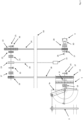
- a first embodiment of the system of the present invention in which there is a first section A suitable for transforming the energy of said wave motion into mechanical energy, a second section B designed to accumulate mechanical energy in the form of potential energy, and a third section C which allows the potential energy to be transformed into electrical energy.
- a thruster 1 also called “body”
- body also called "body”
- constant velocity joint 2
- shaft 3
- semi-compass 4a
- semi-wheel 5
- the thruster 1 is partially immersed in the water, and is capable of receiving a vertical thrust upwards from the wave motion; the shaft 3 is fixed to the propeller 1 and is able to slide along special guides 6 (shown in detail in Fig. 7 ) with a linear pulsating movement vertically, alternatively upwards or downwards.
- the propeller 1 can slide vertically inside shaped cases or poles that delimit its movement.
- the constant velocity joint 2 (indicated in Fig. 1 ) allows the transmission of the movement of the shaft 3 on two non-aligned axes; consequently, the shaft 3 transmits a vertical mechanical movement to the semi-compass 4a which is able to transform the vertical linear movement into a rotary movement.
- the movement of the semi-compass 4a activates the semi-wheel 5, as indicated in Fig. 7 .
- Fig. 1 also shows the second section B of the system in which there are (shown in detail in Fig. 2 ): the semi-wheel 5 operated by the semi-compass 4a which also determines a partial rotation of the main kinematic axis 11, which is coaxial with the secondary kinematic axis 14; the container 15, suitable for containing inside it water taken from said wave mode; the transmission wheel 13 driven by the half-wheel 5; the driven transmission receiving wheel 16, driven by the transmission wheel 13 through the movement of the transmission toothed belt 18; a lifting wheel 19 of the container 15 connected to the driven wheel 16 via the first joint 17 and connected to the water container 15 via the steel cable or toothed transmission belt 20; a lowering wheel 22 of the container 15, connected to the lifting wheel 19 via the second joint 21 and connected to the generator 9 via the toothed belt 24.
- the first joint 17 and the second joint 21 work alternatively.
- Fig. 2 also shows a first brake 35, positioned between the first joint 17 and the lifting wheel 19, useful in case of emergency or for attenuating excess rotations and to avoid return rotations; a device 23, placed between the second joint 21 and the lowering wheel 22, capable of modifying the speed of the system, according to the needs of the generator; a second brake 36, for attenuating the movement of the lowering wheel 22 and for contributing to the required fall speed.
- a first brake 35 positioned between the first joint 17 and the lifting wheel 19, useful in case of emergency or for attenuating excess rotations and to avoid return rotations
- a second brake 36 for attenuating the movement of the lowering wheel 22 and for contributing to the required fall speed.
- sections A and B shown in Fig. 1 and 2 therefore allow, following the impulses of the movement of the shaft 3, of variable intensity and duration, which activate the semi-compass 4a and, consequently, activate the semi-compass - wheel 5 which generates the rotating movement of the secondary kinematic axis 14 and the movement of the toothed transmission belt 18, to allow, in a first phase, the lifting of the container 15 above sea level 50 and up to a height determined for a specific period of time in order to provide an accumulation of said potential energy in the second section B of the system.
- the first joint 17 which had allowed the container 15 loaded with water to be raised is deactivated, and the second joint 21 is instead activated, so as to let the container 15 fall in a controlled manner. with its lowering until it completely descends into the water to transmit the potential energy from the second section B of the system to the third section C of the system.
- Fig. 1 also shows the third section C of the system in which there are (shown in detail in Fig. 2 ): the generator 9, its axis 26, the brake 27, the joint 28 and the device 30 capable of modifying the speed of the generator 9 and to control the mechanical output.
- Section C is therefore able to transform the potential energy coming from section B into electrical energy (in the typical forms of wind turbines), in particular following the lowering of the loaded container 15 after it had been raised to a suitable height for an appropriate period of time useful for storing potential energy.
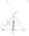
- Fig. 3 shows in detail the semi-compass 4a shown in Fig. 2 , in which the shaft crosspiece 3, a connecting rod 38, a crank 39, and a fixed rotation point 40 are schematically visible.
- the semi-compass 4th allows partial subsequent rotations; in particular, a rotation of 10° is shown in Fig. 3 .
- Fig. 4 shows in detail a portion of section A of the system, in which the semi-compass 4a in the possible extreme positions 41,42 keyed onto the main kinematic axis 11 and two semi-cogwheels 5a,5b coupled laterally with sawtooth recesses 12 which work on the pins 34.
- the first half-cogwheel 5a is provided on the axis of use, called the main kinematic axis 11, and the second half-cogwheel 5b is provided on the secondary kinematic axis 14, coaxial to the main kinematic axis 11.
- the first half-toothed wheel 5a is capable of rotating along two directions of rotation respectively, the first for forceful holding and the second for easy release. Conversely, the half-toothed wheel 5b is capable of rotating only in the direction of the desired motion, with return blocked.
- the transmission wheel 13 or the secondary kinematic axis 14 are toothed and with a retaining spring constitute a ratchet, to allow motion in one direction only and avoid return forces.
- the brake 29 assists in the rotation of the transmission wheel 13 coaxial to the secondary kinematic axis 14.
- Fig. 3 also shows the transmission wheel 13 keyed onto the secondary kinematic axis 14, the cable or traction belt 18, integral with the transmission wheel 13, and the brake 29 on the secondary kinematic axis 14. The teeth and spring of the ratchet are not shown.
- the "sawtooth" toothing of the half-wheels 5 12 provides a “robust” coupling in the direction of rotation and a “slippery” coupling in the opposite direction; this mechanism allows the movement of the shaft 3 to be used both upwards and, by reversing the teeth 12, downwards.
- Fig. 5 further shows in detail the part of section A of Fig. 1 in which the semi-compass 4a and the semi-wheel 5 are present, the latter formed by the female semi-cogwheel 5a keyed onto the main axis 11 and by the male semi-cogwheel 5b keyed onto the secondary axis 14.
- the controlled elastic joint 44 reduces the rigidity of the pulsations and provides, if necessary, for safety disconnection in the event of very rough seas or inactivity of the system (due to maintenance, malfunctions, etc.).
- a thrust spring 8 pushes the male half-gear wheel 5b on the secondary axis 14 towards the female half-gear wheel 5a on the main kinematic axis 11, to obtain an effective coupling.
- the transmission wheel 13 is used, keyed onto the secondary kinematic axis 14 facing a toothed transmission belt or chain 18, as shown in Fig. 6 . In this way, the transmission of the movement to another mechanism can take place. Brake 29 is also shown.
- Fig. 6 shows an embodiment in which a right semi-wheel 5c and a left semi-wheel 5d are simultaneously present, to use the upward and downward movements of the semi-compass 4a.
- Fig. 6 the inversion of the teeth 12 for coupling the two half-wheels 5c and 5d is evident.
- Fig. 7 shows an embodiment in which multiple transmission wheels 13 are assembled in coaxial mode on the same main kinematic axis 11 (each keyed onto its own transmission belt 18 on the secondary kinematic axis 14), to obtain multiple axes secondary kinematics and multiple transmission wheels 13 in the two directions of rotation (high sea and low sea).
- the lateral toothed half-wheel 5 is provided with straight and inverted slots, suitable for the two male half-wheels 5b. This application simplifies the structure of the half-wheels 5.
- the lateral toothed half-wheel 5 has slots on the two sides and is keyed to the main kinematic axis 11, while the two male half-wheels 5b are keyed to the corresponding kinematic axis secondary 14.
- the two male half-wheels 5b rotate in the opposite direction.
- the teeth and spring blocking the reverse rotation to the desired one, in the shape of the ratchet, are not shown in the drawings.
- Fig. 8 shows another embodiment of the system of the present invention, in which at least three different situations can be distinguished: case a) is the one described in the previous figures 1 and 2 , in which there is only one transmission wheel 13 (and its corresponding toothed transmission belt 18 which drives a corresponding driven wheel 16) which manages a single container 15 for water, via a single lifting wheel 19, which reaches a single generator 9 via a single driving wheel lowering 22.
- two towers 7a,7b are also visible, arranged so that the thruster 1 and the shaft 3 fixed to the thruster 1 are placed between the two towers 7a,7b. At least one of the two towers 7a, 7b contains mechanical parts useful for carrying out the transmission of motion in the system of the present invention.
- the tower 7b shown on the right in Figs. 1 and 8 can be intended for the mechanical structure managed by a right mono-rotating gear wheel 5, while the tower 7a shown on the left can be intended for the mechanical structure managed by the rotation of a gear wheel 5 left single rotary. In this way, energy collection is obtained both for the upward and downward motion of the wave.
- the towers 7a,7b can be multiple due to the forces that the propeller 1 imposes on the shaft 3 and the energy transformation mechanisms, so that the overall electrical production can reach many tens or hundreds of Megawatts.
- the towers 7a,7b it is necessary for the towers 7a,7b to have a significant height in order to have a significant gravitational potential energy directly proportional to it, which measured in Joules is expressed: weight, force in Newton x height in metres.
- the heights of the towers are typically several tens of meters, in relation to the amount of energy to be managed.
- the system can also include the presence of multiple trees 3.
- the container 5 for sea water can have, for example, dimensions equal to 4m x 4m x 4m, with a mass of 64,000kg, or a gravitational force of 640,000N. For positioning in a 10 meter high tower, this force collects potential energy of 6,400,000 Joules or a power of 6,400,000 W(J/sec).
- the container 5 can be replaced by a common weight such as those used as counterweights on construction sites, or with waste materials, or with iron whose specific weight of 7,780kg/m3 is very advantageous compared to that of water of around 1,000kg/ m3.
- the propeller 1 is raised by 0.5m compared to the initial basic position, there is a movement of the semi-compass 4a of approximately 10° (as shown in Fig. 3 ). This movement allows a consequent movement of the transmission wheel 13 by 36 times.
- the container 5 can be sized for a lower water content which is brought higher over time, obtaining the same result. This solution makes it possible to lighten the efforts of the mechanical energy transfer structures.
- the structure can be created by providing multiple smaller 5 containers, synchronizing the work phases.
- thruster 1 can be sized differently and the system can be made easier.
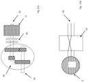
- Fig. 9 shows a detail of the propeller/body 1 of the system of the present invention in which an optical sensor 31 and a strip 32 equipped with holes 33 are visible, where the sensor 31 is integral with the fixed support structure and the strip 32 is integral with the propeller 1.
- the series of holes 33 of the strip 32 is made according to a sequence recognizable by the optical sensor 31 which, by interpreting the sequence, is able to determine the direction and amplitude of the movement of the propeller 1, uphill or downhill.
- the data detected by the optical sensor 31 is transmitted to a central processor, which will be able to control the management of the system, as well as determining the position of the speed change and any brake.
- the "perforated strip 32 - optical sensor 33 reading system” also provides knowledge of the state of the sea, due to its ability to establish the level 50, direction and speed of change. Additional sensors can detect other environmental parameters, such as temperature, wind direction and speed, etc. they will help the overall management by the microprocessor. Furthermore, a digital disk with multiple coded tracks is connected to each axis, for the real-time supply of each management and control movement, transmitted to the microprocessor.
- the microprocessor through a suitable interface, exchanges data sent and received from a remote computer that acts as a control center, via Internet connectivity. Every movement or other data is therefore under remote control for functionality, efficiency, safety and maintenance checks.
- this communication can take place with the current 802.11ac WiFi standard.
- a router with SIM can be inserted that allows connection to the internet.
- the remote control and management unit, the UCR communicates with the plurality of Router devices with SIM in the Systems, or in the stations, to receive and communicate data via the Internet network and/or via a telephone data network connected to the central electronic card U, or a router for each station field.
- the UMTS Universal Mobile Telecommunications System
- Fig. 9 also shows the presence of a sub-box 43 integral with the thruster/box 1 which allows a part of the sub-box 43 itself to be flooded for safety, to counteract the violent forces of the water when the sea is very strong.
- the flooding is carried out using a central microprocessor based on the data detected by the sensors on the force of the sea, acting on a motorized door or valve 45. Once the dangers have been overcome, the initial situation of the device's activity is restored, emptying the sub-caisson 43 by means of a hydraulic pump (not shown in the figures), managed by the microprocessor.
- FIG 10 schematically shows an embodiment of the electric generator 9 of the system of the present invention.
- power electronic components such as, for example, an AC:DC converter 46 which transforms what the generator 9 is capable of producing, with non-stable and non-usable natural frequencies and inconsistent amplitudes, charging capacitor 47 into DC voltage levels.
- a DC:AC converter 48 is used to obtain the required alternating voltages and frequencies, a transformer 49 and a connection line 51.
- the generator 9 used in the system of the present invention can also be a wind generator, an aero-generator, or a synchronous generator for powers in the order of MW.
- Synchronism refers to the rotation speed of the rotor with respect to the stator.
- the wound-type rotor is powered externally and the stator is connected to the electricity grid.
- a transformer brings the voltage to the appropriate levels.
- the power applied to the rotation axis is not always constant, but depends on the availability of the waves.
- the voltage induced in the stator i.e. the magnetic flux
- the output power of the generator is regulated.
- a device capable of modifying the speed is used.
- Fig. 11a shows in detail the speed adaptation device 30 of the generator 9 shown in Fig. 2 with respect to the induced kinematic axis 26; the joint or inserter 28 and the axis 52 of the generator 9 are shown.
- the two poles of the line 54 of the generator 9 are exchanged, as shown in Fig. 11b , by means of an electronic power block 53 controlled by the microprocessor.
- Fig. 12 shows a second alternative embodiment in which, instead of the semi-compass 4a shown in Figs. 1-8 , a rack 4b and a plurality of toothed wheels integral with the rack 4b are shown.
- the rack 4b performs the same function as the semi-compass 4a seen above, i.e. it acts as a device 4 capable of transforming the vertical linear movement of the shaft 3 into a rotary movement.
- the rack 4b can be dimensionally extended to be able to act with many toothed wheels of different sizes.
- Fig. 12 shows in detail the guides 6 along which the propeller 1 slides; furthermore, the shock absorbers 55 necessary to limit the movement of the propeller 1 itself are present.
- the system of the present invention shown above has significant advantages in respecting the environment.
- the towers or stations do not supply themselves with energy products, they do not pollute, they do not emit CO2 or waste, but their production eliminates pollution from traditional generation of equivalent production capacity, being a substitute for it.
- the life of the system is far greater than traditional production stations, in particular due to the use of electric batteries which produce serious problems with the supply of materials, maintenance and disposal.
- the end of life of the system described does not produce residues of polluting products.
- the materials are reusable.
- the system described is positioned "offshore” (i.e. offshore, far from the coast) and is generically presented either as a submerged system or as a fixed structure or as floating equipment.
- the offshore system eliminates the direct visual impact, certainly less than the visual impact caused by the installation of wind poles.
- the system is easily controllable and has no particularly dangerous system parts for the safety of operators, as the system or station can be "switched off", or even partially deactivated, for all maintenance operations.
- the positioning of the system can also be useful as a weather/marine monitoring point.
- the system of the present invention can specifically provide the energy necessary for water desalination applications. This characterization is useful for on-site generation of the much needed energy.
- the system described can easily provide energy with zero raw material costs.
Landscapes
- Engineering & Computer Science (AREA)
- Chemical & Material Sciences (AREA)
- Combustion & Propulsion (AREA)
- Mechanical Engineering (AREA)
- General Engineering & Computer Science (AREA)
- Other Liquid Machine Or Engine Such As Wave Power Use (AREA)
Abstract
Description
- The present invention refers to an electrical energy production system that uses the energy developed by sea waves.
- Nowadays, many techniques for using the sea wave motion to produce energy in different ways are known.
- For example, it is possible to recreate a water drop using basins higher than sea level and narrow passages in the water path, which under the wave pressure allow the water itself to rise to fill the basin. This system allows energy production like classic hydroelectric basins. The limit of this system is that it has very large basins but at very modest heights, leading to non-optimal turbines movement to obtain satisfactory results.
- Other applications are based on the wave motion entering an artefact such as, for example, a water column, and creates motion in an air column activating the turbines.
- Still other applications are based on air containers inflating and deflating under the wave effect and moving the turbines; still other applications are based on floats using the wave amplitude; the motion floats move hydraulic pistons which activate turbines with pressurized liquid. By placing a plurality of these devices in series it is possible to obtain millions of power watts.
- Other systems use pillars anchored to the seabed, equipped with an air chamber subject to compression-decompression cycles, due to the overlying water, formed by a box structure with a large hat covering (of the order of tens of meters high and several meters wide), with the capacity to produce megawatts of power. The main problem of these systems is that the wave motion is at low frequency, while the activation of the electric generators requires higher frequencies.
- Other systems are based on semi-submerged containers containing gyroscopes. The container movement causes the gyroscope movement (with gyroscopic precession) which activates the generators. These applications also require a lot of space. They generate modest quantities of energy, typically 30-40kw with production peaks of 0.2 MW.
- Other systems use marine currents with marine generators similar to wind poles. The application is submerged at different depths, to better intercept the currents; the turbines are therefore moved by the water kinetic force.
- Most of the plants described are offshore and are generally presented either as submerged plants or as fixed structures or as floating equipment.
- However, in order to generate energy in large quantities, the known in the art systems have the disadvantage of requiring a rather complex implementation.
- Furthermore, the known in the art systems are not ecologically advantageous, as they involve high quantities of carbon dioxide production.
- The international patent application published with n.
WO 2007/030841 A1 describes an apparatus for generating electrical energy from sea waves, wherein the apparatus includes: - a pin support having a first portion anchorable to the seabed and a second portion on which a pin mechanism is supported ; - an arm rotatably supported by the pivot mechanism wherein the arm is divided into two portions of unequal length by the pivot mechanism; - a float mounted on a terminal portion of the arm; - a pump actuator connected to the other end of the boom so that, when the boom is pushed up and down due to the action of sea waves on the float, water is pumped by a pump operatively connected to the actuator in response to wave action; and - turbine means for using the water pumped by the pump for the production of electricity. - The European patent application no.
EP 2071181 A1 describes an apparatus for transforming the wave motion energy into another type of usable energy; the apparatus comprises a float having an orifice in the centre, in this orifice there is arranged a rigid pipe firmly hydraulically fixed connected at one of its ends to a flexible tube, and at the other end to a check valve at the end immersed in the water bed. From the opposite end of the pipe, which joins hydraulically to the rigid pipe, the pipe terminates in a water tank located on dry ground and above mean sea level. - US Patent Application No.
US 2017/016425 A1 describes a power generation system including a floating body, a transmission device, a transport tank, an upper container and a power generating assembly. The drive device is driven by a sea force or a buoyant force through the floating body to raise the transport tank to a first position, which is close to the upper container, or to lower the transport tank to a second position, which is at a lower level than the electric motor to recycle solid particles. - Therefore, the Applicant faced the technical problem of how to create an electricity production system using sea waves in a simple, economically and commercially advantageous way, while respecting the environment.
- The present invention refers to an electrical energy production system such as that one indicated in
claim 1. - The Applicant of the present application has in fact surprisingly found that the technical problem encountered above can be solved effectively and reliably by means of an electrical energy production system capable of using the energy created by a wave motion, in which said system includes: a ) a first section suitable for transforming the energy of said wave motion into mechanical energy, b) a second section suitable for accumulating said mechanical energy in the form of potential energy, and c) a third section which includes a device suitable for producing a reduction of called potential energy in electrical energy,
- This first section includes:
- i) a propeller semi-immersed in water capable of receiving a vertical thrust upwards from said wave motion,
- ii) at least one shaft fixed to said thruster, capable of moving with a vertical linear pulsating movement, alternatively upwards or downwards,
- iii) at least one device capable of transforming said vertical linear movement of said at least one shaft into a rotary movement,
- iv) at least one half-wheel suitable for engaging with said device suitable for transforming said vertical linear movement of said at least one shaft into a rotary movement.
- Furthermore, said second section includes:
- v) at least one container capable of containing water taken from said waveform;
- vi) at least one transmission wheel capable of being driven by said half-wheel,
- vii) at least one driven wheel connected to said drive wheel;
- viii) at least one container lifting wheel integral with said at least one towed wheel,
- ix) at least a first joint suitable for connecting said towed wheel with said lifting wheel so as to allow the lifting of said container up to a specific height for a specific period of time in order to provide an accumulation of said potential energy in said second section of the system;
- x) at least one container lowering wheel, connected to said towed wheel;
- xi) at least a second joint suitable for connecting said lifting wheel with said lowering wheel so as to allow the lowering of said container until it is completely lowered into the water to transmit said potential energy from said second section of the system to said third section of the system.
- Said third section includes at least one generator capable of being connected to said lowering wheel.
- In this way, the system of the present invention allows electricity to be generated in a simple and ecological way, as no significant quantities of carbon dioxide are emitted.
- In fact, said container reaches the water level and fills with water in a so-called "rest" phase; subsequently, said container "loaded with water" is gradually raised to a height of the order of many tens of metres, in the so-called "working" phase, following an energy impulse supplied by the waves to the device capable of transforming said vertical linear movement of said at least one shaft into a rotary movement. Subsequently, the container is sent downhill, under control, with the action of gravity, until it completely descends into the water, in order to activate the electric generators.
- The energy necessary to lift the water is obtained from the Archimedean thrust coming from a thruster, under the action of the waves.
- According to a preferred embodiment, said thruster is a closed box, of material and weight determined in equilibrium by the forces so that it can float.
- According to a preferred embodiment, said "water-filled" container has the shape of a cube, for example with dimensions of 4m x 4m x 4m, providing a mass of 64,000kg or a gravitational force of 640,000N. For a positioning in the 10 meter high tower, this force collects potential energy of 6,400,000 Joules or a power of 6,400,000 W(J/sec). In other embodiments, said container can be sized so as to have a lower water content and be brought higher over time. In this way, the efforts of the mechanical structures for energy transfer are lightened. The structure can be created to have many smaller containers and synchronize the work phases.
- According to other preferred embodiments, said container, like the propeller, has a spherical, parallelepiped, octagonal, oval, cylindrical shape, etc.
- According to an alternative embodiment, said container can be replaced by a common weight such as those used as counterweights on construction sites, or with waste materials, or with iron, whose specific weight of 7,780kg/m3 is very advantageous compared to that of water, which is approximately 1,000kg/m3.
- According to a preferred embodiment, the system further comprises at least one constant velocity joint placed between said thruster and said at least one shaft.
- In this way it is possible to obtain the transmission of movement on two non-aligned axes. In fact, the constant velocity joint is a device for transmitting motion between two shafts which allows the transmission to be maintained, regardless of the angle of inclination between the shafts themselves. In particular, considering that the engine maintains some degrees of freedom, the constant velocity joint can freely transmit the movement to the shaft which will therefore have the necessary precision and will not be able to go outside certain limits.
- According to a preferred embodiment, the system further comprises at least one guide suitable for engaging with said at least one shaft so as to allow each of said at least one shaft to move along a corresponding one of said at least one guide with a vertical linear pulsating movement, alternately up or down.
- According to a preferred embodiment, said device suitable for transforming said vertical linear movement of said at least one shaft into a rotary movement comprises a semi-compass.
- In this way, thanks to the presence of the semi-compass, the linear vertical movement forces of variable dimensions are transferred into fractional rotation movement forces on axles and wheels, limited, but proportionate to the intensity of the forces. In fact, the impulses of the movement of the shaft, of variable intensity and duration, thanks to the action of the semi-compass, produce the rotating movement of the transmission belt.
- According to a preferred alternative embodiment, said device suitable for transforming said vertical linear movement of said at least one shaft into a rotary movement comprises a rack and at least one toothed wheel which interacts with said rack.
- According to a preferred embodiment, said rack is dimensionally extended.
- In this way, the rack can interact with many gear wheels of different sizes. The system can take the shape of many trees.
- According to a preferred embodiment, said half-wheel (5) comprises a first half-wheel keyed coaxially on a main kinematic axis and a second half-wheel keyed on a secondary kinematic axis, in which said first half-wheel is suitable for rotate in two directions of rotation and said second half-wheel is capable of rotating along only one direction.
- In this way, it is possible to exploit both vertical movements, alternatively upwards and downwards, of the at least one thruster shaft which move the semi-compass and impart a rotation of the main kinematic axis in two possible directions: the first half-wheel is able to rotate respectively along two directions of rotation, the first for forceful holding and the second for easy release. Conversely, the second half-wheel is capable of rotating along a single direction of rotation in the direction of the desired motion, with return blocked.
- According to a preferred embodiment, each of said first and second half-wheels are provided with teeth in the shape of saw teeth.
- In this way, by reversing the shape of the saw teeth of the half-geared wheels, it is possible to choose the appropriate direction of rotation.
- According to a preferred embodiment, there are pins on which said saw teeth engage.
- According to a preferred embodiment, suitable springs are present to push said pins.
- In this way, thanks to the thrust exerted on the pins, it is possible to reverse the direction of the saw teeth.
- According to a preferred embodiment, the system of the present invention also includes at least two towers (also called "stations"), designed to contain further mechanical parts suitable for carrying out the transmission of motion in said system.
- According to a preferred embodiment, said at least one tower is suitable for containing a system rotating on multiple axes in the same direction, coaxially coupled to each other by means of joints.
- In this way the joints allow the rotation of the axles and the wheels keyed into them.
- According to a preferred embodiment, said towers can be at least in blocks of at least two, preferably at least four; however, the towers can be replicated in any number.
- In this way, the overall electrical production can reach many tens or hundreds of Megawatts.
- According to a preferred embodiment, two of said towers are arranged so that said thruster and said shaft fixed to said thruster are interposed between said two towers.
- In this way, one of said two towers is intended to house the mechanical structure intended for collecting the energy due to the uphill wave motion and the other of said two towers is intended to house the mechanical structure intended for collecting the energy due to the descending wave motion.
- According to a preferred embodiment, each of said towers is several tens of meters high, for example 100 meters, as in the case of wind turbine poles, to obtain accumulated powers of considerable size.
- The height of these towers is established in relation to the amount of energy to be managed.
- In this way, a significant gravitational potential energy is obtained directly proportional to it, typically measured in Joules, expressed as weight force in Newtons x height in meters.
- According to a preferred embodiment, the system of the present invention further comprises at least one generator speed modifier.
- In this way, the generator is allowed to work in optimal conditions.
- According to a preferred embodiment, the system of the present invention also includes at least one optical sensor and a strap equipped with a hole integral with said thruster, in which said hole is made according to a sequence recognizable by said optical sensor integral with the fixed structure.
- In this way, the optical sensor is able to interpret this sequence and, consequently, is able to determine the direction of the movement, the amplitude of the movement, and therefore determine whether the movement is up or down.
- According to a preferred embodiment, the system of the present invention further comprises at least one microprocessor suitable for operating the mechanical elements of the system.
- In this way, said microprocessor is able to receive the data detected by said optical sensor, integral with the fixed structure, such as, for example, temperature, wind, wave level, etc. Consequently, by comparing the data detected with that of the data set in the programming, said microprocessor is able to provide for the management and control of the actuators, such as for example joints, brakes, speed, electro-controls and commands, safety assessments.
- According to a preferred embodiment, the system of the present invention also includes at least one remote station capable of interacting with said microprocessor via a digital connection, for example via Internet connectivity.
- According to a preferred embodiment, the system of the present invention further comprises at least one safety container, arranged below said thruster and integral with it.
- In this way, when the sea wave motion is very strong, said safety container floods, safeguarding the system from exaggerated forces.
- According to a preferred embodiment, the system of the present invention also includes at least one motorized door or valve activated/deactivated by said microprocessor which regulates the flooding of said safety container based on the data detected by said optical sensor.
- According to a preferred embodiment, the system of the present invention further comprises at least one hydraulic pump, operated by said microprocessor.
- In this way, once the very strong wave motion situation is over, said safety container is emptied via said hydraulic pump, restoring the initial situation.
- According to a preferred embodiment, the system of the present invention further includes shock absorbers which interact with the movement of said thruster.
- At this node, the movement of the thruster itself is limited.
- Further characteristics and advantages of the present invention will be better highlighted by examining the following detailed description of preferred, but not exclusive, embodiments, illustrated for indicative and non-limiting purposes only with the support of the attached drawings. In particular, in such drawings:
-
Fig. 1 is an overall schematic view of an embodiment of the system according to a first aspect of the present invention; -
Fig. 2 shows sections B and C ofFig. 1 in detail; -
Fig. 3 shows a detail of the semi-compass shown inFig. 1 and2 ; -
Fig. 4 shows a detail of the action of the semi-compass on the traction wheel; -
Fig. 5 shows in further detail the part of section A ofFig. 1 in which the semi-compass and the semi-wheel are present; -
Fig. 6 shows an embodiment in which a right half-wheel and a left half-wheel are simultaneously present; -
Fig. 7 shows an embodiment in which multiple transmission wheels are assembled coaxially on the same main kinematic axis; -
Fig. 8 is an overall schematic view of a further embodiment of the system of the present invention; -
Fig. 9 shows a detail of the propeller/body of the system of the present invention; -
Fig. 10 schematically shows an embodiment of the generator of the system of the present invention; -
Fig. 11a and 11b show in detail a device for adapting to the speed of the generator inFig. 2 ; -
Fig. 12 shows a detail of an embodiment of the system of the present invention which includes a rack. - The following detailed description refers to particular embodiments of the system of the present invention, without limiting its content.
- With reference to
Fig. 1 , and in detail toFig. 2 , a first embodiment of the system of the present invention is described, in which there is a first section A suitable for transforming the energy of said wave motion into mechanical energy, a second section B designed to accumulate mechanical energy in the form of potential energy, and a third section C which allows the potential energy to be transformed into electrical energy. - In the first section A there is a thruster 1 (also called "body"), a constant velocity joint 2, a
shaft 3, a semi-compass 4a, and asemi-wheel 5. - In particular, the
thruster 1 is partially immersed in the water, and is capable of receiving a vertical thrust upwards from the wave motion; theshaft 3 is fixed to thepropeller 1 and is able to slide along special guides 6 (shown in detail inFig. 7 ) with a linear pulsating movement vertically, alternatively upwards or downwards. Thepropeller 1 can slide vertically inside shaped cases or poles that delimit its movement. - The constant velocity joint 2 (indicated in
Fig. 1 ) allows the transmission of the movement of theshaft 3 on two non-aligned axes; consequently, theshaft 3 transmits a vertical mechanical movement to the semi-compass 4a which is able to transform the vertical linear movement into a rotary movement. The movement of the semi-compass 4a activates thesemi-wheel 5, as indicated inFig. 7 . -
Fig. 1 also shows the second section B of the system in which there are (shown in detail inFig. 2 ): the semi-wheel 5 operated by the semi-compass 4a which also determines a partial rotation of the mainkinematic axis 11, which is coaxial with the secondarykinematic axis 14; thecontainer 15, suitable for containing inside it water taken from said wave mode; thetransmission wheel 13 driven by the half-wheel 5; the driventransmission receiving wheel 16, driven by thetransmission wheel 13 through the movement of the transmissiontoothed belt 18; alifting wheel 19 of thecontainer 15 connected to the drivenwheel 16 via the first joint 17 and connected to thewater container 15 via the steel cable ortoothed transmission belt 20; a loweringwheel 22 of thecontainer 15, connected to thelifting wheel 19 via the second joint 21 and connected to thegenerator 9 via thetoothed belt 24. The first joint 17 and the second joint 21 work alternatively. The first closed in the lift of 15 and the second closed in the descent of 15. -
Fig. 2 also shows afirst brake 35, positioned between the first joint 17 and thelifting wheel 19, useful in case of emergency or for attenuating excess rotations and to avoid return rotations; adevice 23, placed between the second joint 21 and the loweringwheel 22, capable of modifying the speed of the system, according to the needs of the generator; asecond brake 36, for attenuating the movement of the loweringwheel 22 and for contributing to the required fall speed. - The elements present in sections A and B shown in
Fig. 1 and2 therefore allow, following the impulses of the movement of theshaft 3, of variable intensity and duration, which activate the semi-compass 4a and, consequently, activate the semi-compass -wheel 5 which generates the rotating movement of the secondarykinematic axis 14 and the movement of thetoothed transmission belt 18, to allow, in a first phase, the lifting of thecontainer 15 abovesea level 50 and up to a height determined for a specific period of time in order to provide an accumulation of said potential energy in the second section B of the system. Subsequently, in a second phase, when necessary, the first joint 17 which had allowed thecontainer 15 loaded with water to be raised is deactivated, and the second joint 21 is instead activated, so as to let thecontainer 15 fall in a controlled manner. with its lowering until it completely descends into the water to transmit the potential energy from the second section B of the system to the third section C of the system. -
Fig. 1 also shows the third section C of the system in which there are (shown in detail inFig. 2 ): thegenerator 9, itsaxis 26, thebrake 27, the joint 28 and thedevice 30 capable of modifying the speed of thegenerator 9 and to control the mechanical output. Section C is therefore able to transform the potential energy coming from section B into electrical energy (in the typical forms of wind turbines), in particular following the lowering of the loadedcontainer 15 after it had been raised to a suitable height for an appropriate period of time useful for storing potential energy. -
Fig. 3 shows in detail the semi-compass 4a shown inFig. 2 , in which theshaft crosspiece 3, a connectingrod 38, acrank 39, and afixed rotation point 40 are schematically visible. The semi-compass 4th allows partial subsequent rotations; in particular, a rotation of 10° is shown inFig. 3 . -
Fig. 4 shows in detail a portion of section A of the system, in which the semi-compass 4a in the possibleextreme positions kinematic axis 11 and two semi-cogwheels 5a,5b coupled laterally withsawtooth recesses 12 which work on thepins 34. The first half-cogwheel 5a is provided on the axis of use, called the mainkinematic axis 11, and the second half-cogwheel 5b is provided on the secondarykinematic axis 14, coaxial to the mainkinematic axis 11. - The first half-
toothed wheel 5a is capable of rotating along two directions of rotation respectively, the first for forceful holding and the second for easy release. Conversely, the half-toothed wheel 5b is capable of rotating only in the direction of the desired motion, with return blocked. Thetransmission wheel 13 or the secondarykinematic axis 14 are toothed and with a retaining spring constitute a ratchet, to allow motion in one direction only and avoid return forces. Thebrake 29 assists in the rotation of thetransmission wheel 13 coaxial to the secondarykinematic axis 14. From the action of the semi-compass 4a onwards, the choice of the appropriate direction of rotation occurs by inverting the shape of thesaw teeth 12 of thesemi-toothed wheels pins 34 pushed bysprings 8.Fig. 3 also shows thetransmission wheel 13 keyed onto the secondarykinematic axis 14, the cable ortraction belt 18, integral with thetransmission wheel 13, and thebrake 29 on the secondarykinematic axis 14. The teeth and spring of the ratchet are not shown. - The "sawtooth" toothing of the half-
wheels 5 12 provides a "robust" coupling in the direction of rotation and a "slippery" coupling in the opposite direction; this mechanism allows the movement of theshaft 3 to be used both upwards and, by reversing theteeth 12, downwards. -
Fig. 5 further shows in detail the part of section A ofFig. 1 in which the semi-compass 4a and thesemi-wheel 5 are present, the latter formed by thefemale semi-cogwheel 5a keyed onto themain axis 11 and by themale semi-cogwheel 5b keyed onto thesecondary axis 14. The controlled elastic joint 44 reduces the rigidity of the pulsations and provides, if necessary, for safety disconnection in the event of very rough seas or inactivity of the system (due to maintenance, malfunctions, etc.). Athrust spring 8 pushes the male half-gear wheel 5b on thesecondary axis 14 towards the female half-gear wheel 5a on the mainkinematic axis 11, to obtain an effective coupling. To transmit the motion, thetransmission wheel 13 is used, keyed onto the secondarykinematic axis 14 facing a toothed transmission belt orchain 18, as shown inFig. 6 . In this way, the transmission of the movement to another mechanism can take place.Brake 29 is also shown. -
Fig. 6 shows an embodiment in which aright semi-wheel 5c and a left semi-wheel 5d are simultaneously present, to use the upward and downward movements of the semi-compass 4a. InFig. 6 the inversion of theteeth 12 for coupling the two half-wheels -
Fig. 7 shows an embodiment in whichmultiple transmission wheels 13 are assembled in coaxial mode on the same main kinematic axis 11 (each keyed onto itsown transmission belt 18 on the secondary kinematic axis 14), to obtain multiple axes secondary kinematics andmultiple transmission wheels 13 in the two directions of rotation (high sea and low sea). In particular, the lateral toothed half-wheel 5 is provided with straight and inverted slots, suitable for the two male half-wheels 5b. This application simplifies the structure of the half-wheels 5. It is observed that the lateral toothed half-wheel 5 has slots on the two sides and is keyed to the mainkinematic axis 11, while the two male half-wheels 5b are keyed to the corresponding kinematic axis secondary 14. The two male half-wheels 5b rotate in the opposite direction. The teeth and spring blocking the reverse rotation to the desired one, in the shape of the ratchet, are not shown in the drawings. -
Fig. 8 shows another embodiment of the system of the present invention, in which at least three different situations can be distinguished: case a) is the one described in the previousfigures 1 and2 , in which there is only one transmission wheel 13 (and its correspondingtoothed transmission belt 18 which drives a corresponding driven wheel 16) which manages asingle container 15 for water, via asingle lifting wheel 19, which reaches asingle generator 9 via a single driving wheel lowering 22. In case b) with just one transmission wheel 13 (and with its corresponding transmission toothed belt 18) three towedwheels 16 are activated which transmit motion to threeseparate lifting wheels 19 to manage threecontainers 15 for the water, then transmitting the motion to three distinct loweringwheels 22 of thecontainer 15, to reach threedistinct generators 9 via correspondingtoothed belts 24. In case c) there are three transmission wheels 13 (each integral with a corresponding belt toothed transmission 18), each of which manages adifferent container 15 for water (for a total of three containers), each of which reaches asingle generator 9. The joints present allow you to select whichtransmission wheel 13 to enable. - In
Fig. 1 and8 , twotowers thruster 1 and theshaft 3 fixed to thethruster 1 are placed between the twotowers towers - The
tower 7b shown on the right inFigs. 1 and8 can be intended for the mechanical structure managed by a right mono-rotatinggear wheel 5, while thetower 7a shown on the left can be intended for the mechanical structure managed by the rotation of agear wheel 5 left single rotary. In this way, energy collection is obtained both for the upward and downward motion of the wave. - The
towers propeller 1 imposes on theshaft 3 and the energy transformation mechanisms, so that the overall electrical production can reach many tens or hundreds of Megawatts. - It is necessary for the
towers - The system can also include the presence of
multiple trees 3. - The
container 5 for sea water can have, for example, dimensions equal to 4m x 4m x 4m, with a mass of 64,000kg, or a gravitational force of 640,000N. For positioning in a 10 meter high tower, this force collects potential energy of 6,400,000 Joules or a power of 6,400,000 W(J/sec). - The
container 5 can be replaced by a common weight such as those used as counterweights on construction sites, or with waste materials, or with iron whose specific weight of 7,780kg/m3 is very advantageous compared to that of water of around 1,000kg/ m3. - For a principle evaluation, following the hypothesis in the chosen sea, of a recurring theoretical wave per minute, there are 60 waves per hour and 1,440 waves per day.
- For example, if at the expense of the wave, the
propeller 1 is raised by 0.5m compared to the initial basic position, there is a movement of the semi-compass 4a of approximately 10° (as shown inFig. 3 ). This movement allows a consequent movement of thetransmission wheel 13 by 36 times. - Consequently, 36 waves (36x10°) are needed to complete one revolution of the secondary
kinematic axis 14, in "about half an hour" of time. For atransmission wheel 13 of approximately 3 meters in diameter, on the secondarykinematic axis 14, the path of thebelt 18 is 10m (3×3.14)). If the towedwheel 16 receiving the input on the induced kinematic axis has the same dimensions, with 36 waves thecontainer 15 for sea water is raised by 10m. - For each of the 36 phases considered, each corresponding to an amplitude of the semi-compass 4a of 10°, every 0.5m of each wave, the minimum energy required is 6.4MJ/36 = 180,000 Joules.
- Evaluating the 0.5m rise of the
thruster 1 and the crossbar of theshaft 3, compared to the stable equilibrium position of the floating, there is a further thrust force of 10m x 10m x 0.5m x 1,000 kg x 9.81 = 500,000N at each stage. This force is greater than that necessary to move the semi-compass 4a which will raise the container, 500,000 N x 0.5m = 250,000 Joules, which is greater than the 180,000 Joules seen above, as necessary. - In another embodiment, the
container 5 can be sized for a lower water content which is brought higher over time, obtaining the same result. This solution makes it possible to lighten the efforts of the mechanical energy transfer structures. The structure can be created by providing multiple smaller 5 containers, synchronizing the work phases. - Similarly,
thruster 1 can be sized differently and the system can be made easier. -
Fig. 9 shows a detail of the propeller/body 1 of the system of the present invention in which an optical sensor 31 and astrip 32 equipped withholes 33 are visible, where the sensor 31 is integral with the fixed support structure and thestrip 32 is integral with thepropeller 1. The series ofholes 33 of thestrip 32 is made according to a sequence recognizable by the optical sensor 31 which, by interpreting the sequence, is able to determine the direction and amplitude of the movement of thepropeller 1, uphill or downhill. The data detected by the optical sensor 31 is transmitted to a central processor, which will be able to control the management of the system, as well as determining the position of the speed change and any brake. The "perforated strip 32 -optical sensor 33 reading system" also provides knowledge of the state of the sea, due to its ability to establish thelevel 50, direction and speed of change. Additional sensors can detect other environmental parameters, such as temperature, wind direction and speed, etc. they will help the overall management by the microprocessor. Furthermore, a digital disk with multiple coded tracks is connected to each axis, for the real-time supply of each management and control movement, transmitted to the microprocessor. - The microprocessor, through a suitable interface, exchanges data sent and received from a remote computer that acts as a control center, via Internet connectivity. Every movement or other data is therefore under remote control for functionality, efficiency, safety and maintenance checks.
- In this way it is possible to know in real time all the environmental and operating parameters, productivity, critical issues, any anomalies, and anything else deemed necessary or appropriate. In fact, it is the task of the Internet connection to exchange data, for example through one or more "Remote UCR central units", for the management of the entire system or production park and the data exchange of all the programmed functions.
- By way of example, this communication can take place with the current 802.11ac WiFi standard. For example, a router with SIM can be inserted that allows connection to the internet. The remote control and management unit, the UCR, communicates with the plurality of Router devices with SIM in the Systems, or in the stations, to receive and communicate data via the Internet network and/or via a telephone data network connected to the central electronic card U, or a router for each station field.
- In particular, in the router the UMTS (Universal Mobile Telecommunications System) module stores the data detected and periodically sends them to the remote UCR central unit.
-
Fig. 9 also shows the presence of a sub-box 43 integral with the thruster/box 1 which allows a part of the sub-box 43 itself to be flooded for safety, to counteract the violent forces of the water when the sea is very strong. The flooding is carried out using a central microprocessor based on the data detected by the sensors on the force of the sea, acting on a motorized door orvalve 45. Once the dangers have been overcome, the initial situation of the device's activity is restored, emptying the sub-caisson 43 by means of a hydraulic pump (not shown in the figures), managed by the microprocessor. -
Figure 10 schematically shows an embodiment of theelectric generator 9 of the system of the present invention. For the normalization of the frequency and electrical voltage levels, power electronic components are used, such as, for example, an AC:DC converter 46 which transforms what thegenerator 9 is capable of producing, with non-stable and non-usable natural frequencies and inconsistent amplitudes, chargingcapacitor 47 into DC voltage levels. Subsequently, a DC:AC converter 48 is used to obtain the required alternating voltages and frequencies, atransformer 49 and aconnection line 51. - The
generator 9 used in the system of the present invention can also be a wind generator, an aero-generator, or a synchronous generator for powers in the order of MW. Synchronism refers to the rotation speed of the rotor with respect to the stator. The wound-type rotor is powered externally and the stator is connected to the electricity grid. A transformer brings the voltage to the appropriate levels. - In a direct application of the movement to the
generator 9, the power applied to the rotation axis is not always constant, but depends on the availability of the waves. By varying the voltage induced in the stator, i.e. the magnetic flux, the output power of the generator is regulated. To have the most constant speed possible, a device capable of modifying the speed is used. -
Fig. 11a shows in detail thespeed adaptation device 30 of thegenerator 9 shown inFig. 2 with respect to the inducedkinematic axis 26; the joint orinserter 28 and theaxis 52 of thegenerator 9 are shown. In order to reverse the rotation of the generator, the two poles of theline 54 of thegenerator 9 are exchanged, as shown inFig. 11b , by means of anelectronic power block 53 controlled by the microprocessor. -
Fig. 12 shows a second alternative embodiment in which, instead of the semi-compass 4a shown inFigs. 1-8 , arack 4b and a plurality of toothed wheels integral with therack 4b are shown. Therack 4b performs the same function as the semi-compass 4a seen above, i.e. it acts as a device 4 capable of transforming the vertical linear movement of theshaft 3 into a rotary movement. Therack 4b can be dimensionally extended to be able to act with many toothed wheels of different sizes. - Similarly to what is shown in the previous figures which show a semi-compass, also in the embodiment of
Fig. 12 in which therack 4b is shown there are thethruster 1, theshaft 3, thetoothed wheels 5 for therack 4b, thetransmission wheel 13 and the belt integral with it 18, the drivenwheel 16, the inserter joints 17 and 21 to facilitate the coupling of the drivenwheel 16, respectively, with therespective lifting wheels 19 and loweringwheels 22. Furthermore,Fig. 12 shows in detail theguides 6 along which thepropeller 1 slides; furthermore, theshock absorbers 55 necessary to limit the movement of thepropeller 1 itself are present. - The system of the present invention shown above has significant advantages in respecting the environment. In fact, the towers or stations do not supply themselves with energy products, they do not pollute, they do not emit CO2 or waste, but their production eliminates pollution from traditional generation of equivalent production capacity, being a substitute for it. The life of the system is far greater than traditional production stations, in particular due to the use of electric batteries which produce serious problems with the supply of materials, maintenance and disposal. The end of life of the system described does not produce residues of polluting products. The materials are reusable.
- The system described is positioned "offshore" (i.e. offshore, far from the coast) and is generically presented either as a submerged system or as a fixed structure or as floating equipment. The offshore system eliminates the direct visual impact, certainly less than the visual impact caused by the installation of wind poles.
- Energy is available when required. Multiple synchronized stations can be created to give production continuity to the network, even of considerable power.
- The system is easily controllable and has no particularly dangerous system parts for the safety of operators, as the system or station can be "switched off", or even partially deactivated, for all maintenance operations.
- The positioning of the system can also be useful as a weather/marine monitoring point. The system of the present invention can specifically provide the energy necessary for water desalination applications. This characterization is useful for on-site generation of the much needed energy.
- These operations, according to current technologies, take place either by reverse osmosis with the use of particular filters, pressure pumps or in the thermal form, with evaporation and subsequent condensation. The choice depends on installation costs, maintenance costs, maintenance and location. It depends a lot on the quantity of water to be treated, the quality of the results, the quantity of residues to be disposed of.
- The system described can easily provide energy with zero raw material costs.
- Of course, many modifications and variations of the preferred embodiments described above will be apparent to those skilled in the art, while still remaining within the scope of the invention.
- Therefore, the present invention is not limited to the preferred embodiments described, illustrated for illustrative and non-limiting purposes only, but is defined by the claims that follow.
Claims (10)
- Electricity production system suitable for using the energy created by a wave motion, wherein said electricity production system comprises: a) a first section (A) suitable for transforming the energy of said wave motion into mechanical energy, b) a second section (B) adapted to accumulate said mechanical energy in the form of potential energy, and c) a third section (C) adapted to produce a reduction of said potential energy into electrical energy,
wherein,said first section (A) includes:i) a propeller (1) semi-immersed in water capable of receiving a vertical upward thrust from said wave motion,ii) at least one shaft (3) fixed to said propeller (1) capable of moving with a vertical linear pulsating movement, alternately upwards or downwards,iii) at least one device (4) able to transform said vertical linear movement of said at least one shaft (3) into a rotary movement,iv) at least one half-wheel (5) able to engage with said device (4);wherein, said second section (B) comprises:v) at least one container (15) able to contain at its inside the water taken from said wave motion;vi) at least one transmission wheel (13) adapted to be driven by said semi-wheel (5),vii) at least one trailed wheel (16) connected to said transmission wheel (13);viii) at least one lifting wheel (19) of the container (15) integral with said at least one trailed wheel (16),ix) at least one first joint (17) able to connect said trailed wheel (16) with said lifting wheel (19) so as to allow the lifting of said container (15) up to a given height for a determined period of time in order to provide a storage of said potential energy in said second section (B) of the electricity production system;x) at least one lowering wheel (22) of the container (15), connected to said trailed wheel (16);xi) at least one second joint (21) able to connect said lifting wheel (19) with said lowering wheel (22) so as to allow the lowering of said container (15) until the complete descent into the water to transmit said potential energy from said second section (B) of the electricity production system to said third section (C) of the electricity production system;and wherein said third section (C) comprises:
xii) at least one generator (9) adapted to be connected to said lowering wheel (22). - Electricity production system according to claim 1, which further comprises at least one homokinetic joint (2) placed between said propeller (1) and said at least one shaft (3).
- Electricity production system according to any one of the preceding claims, wherein said device (4) suitable for transforming said vertical linear movement of said at least one shaft (3) into a rotary movement comprises a semi-compass (4a).
- Electricity production system according to any one of claims 1 or 2, wherein said device (4) able to transform said vertical linear movement of said at least one shaft (3) into a rotary movement comprises a rack (4b).
- Electricity production system according to any one of the preceding claims wherein said half-wheel (5) includes a first sprocket half-wheel (5a), keyed coaxially on a main kinematic axis (11) and a second sprocket half-wheel (5b) keyed on a secondary kinematic axis ( 14), wherein said first sprocket half-wheel (5a) is able to rotate along two rotation directions, while said second sprocket half-wheel (5b) is able to rotate along a single direction of rotation in the direction of the desired motion.
- Electricity production system according to any one of the preceding claims which further comprises at least one speed modifier (30) of the generator (9).
- Electricity production system according to any one of the preceding claims which further comprises at least one optical sensor (31) and a strap (32) equipped with a hole (33) integral with said propeller (1), wherein said hole (33) is made according to a sequence recognizable by said optical sensor (31) which, according to the recognized sequence, is able to determine the movement direction of the propeller (1), upwards or downwards.
- Electricity production system according to any one of the preceding claims which further comprises at least two towers (7a,7b) suitable for containing further mechanical parts suitable for realizing the motion transmission in said electricity production system, and arranged so that said propeller (1) and said shaft (3) fixed to propeller (1) are interposed between the two towers (7a,7b).
- Electricity production system according to any one of the preceding claims, which further comprises at least one microprocessor adapted to actuate the activities of the mechanical elements of the electricity production system.
- Electricity production system according to claim 9 which further comprises at least one remote station able to interact through a digital link with said microprocessor.
Applications Claiming Priority (1)
| Application Number | Priority Date | Filing Date | Title |
|---|---|---|---|
| IT102023000013176A IT202300013176A1 (en) | 2023-06-26 | 2023-06-26 | ELECTRICITY PRODUCTION SYSTEM THAT USES THE ENERGY DEVELOPED BY SEA WAVES |
Publications (3)
| Publication Number | Publication Date |
|---|---|
| EP4484742A1 true EP4484742A1 (en) | 2025-01-01 |
| EP4484742C0 EP4484742C0 (en) | 2026-03-04 |
| EP4484742B1 EP4484742B1 (en) | 2026-03-04 |
Family
ID=88413451
Family Applications (1)
| Application Number | Title | Priority Date | Filing Date |
|---|---|---|---|
| EP24020184.8A Active EP4484742B1 (en) | 2023-06-26 | 2024-06-06 | Electricity production system using the energy developed by sea waves |
Country Status (2)
| Country | Link |
|---|---|
| EP (1) | EP4484742B1 (en) |
| IT (1) | IT202300013176A1 (en) |
Citations (5)
| Publication number | Priority date | Publication date | Assignee | Title |
|---|---|---|---|---|
| GB2068469A (en) * | 1980-01-31 | 1981-08-12 | Sendra Zurita H | Electrical power station driven by wave energy |
| WO2007030841A1 (en) * | 2005-09-06 | 2007-03-15 | Johannes Jacobus Vosloo | Sea swells power electricity generation apparatus |
| EP2071181A1 (en) * | 2006-09-04 | 2009-06-17 | Power Retailing Group, S.A. De C.V. | Wave pump used to convert wave energy into another type of usable energy |
| US20170016425A1 (en) * | 2015-07-17 | 2017-01-19 | Wen-Chieh Chen | Power generation system |
| WO2022055469A1 (en) * | 2020-09-11 | 2022-03-17 | Виктор Иванович ЗАБАЙРАЧНЫЙ | Method for producing electrical energy from wave energy, device and offshore energy island for the implementation thereof |
-
2023
- 2023-06-26 IT IT102023000013176A patent/IT202300013176A1/en unknown
-
2024
- 2024-06-06 EP EP24020184.8A patent/EP4484742B1/en active Active
Patent Citations (5)
| Publication number | Priority date | Publication date | Assignee | Title |
|---|---|---|---|---|
| GB2068469A (en) * | 1980-01-31 | 1981-08-12 | Sendra Zurita H | Electrical power station driven by wave energy |
| WO2007030841A1 (en) * | 2005-09-06 | 2007-03-15 | Johannes Jacobus Vosloo | Sea swells power electricity generation apparatus |
| EP2071181A1 (en) * | 2006-09-04 | 2009-06-17 | Power Retailing Group, S.A. De C.V. | Wave pump used to convert wave energy into another type of usable energy |
| US20170016425A1 (en) * | 2015-07-17 | 2017-01-19 | Wen-Chieh Chen | Power generation system |
| WO2022055469A1 (en) * | 2020-09-11 | 2022-03-17 | Виктор Иванович ЗАБАЙРАЧНЫЙ | Method for producing electrical energy from wave energy, device and offshore energy island for the implementation thereof |
Also Published As
| Publication number | Publication date |
|---|---|
| IT202300013176A1 (en) | 2024-12-26 |
| EP4484742C0 (en) | 2026-03-04 |
| EP4484742B1 (en) | 2026-03-04 |
Similar Documents
| Publication | Publication Date | Title |
|---|---|---|
| EP1960660B1 (en) | Wave energy recovery system | |
| JP5858241B2 (en) | Device for generating electrical energy from waves | |
| CN102132034B (en) | An oceanic wave energy utilization system | |
| EP1687527B1 (en) | Energy generating system using sea waves | |
| EP2389506B1 (en) | Modular array type energy converter | |
| EP2580467B1 (en) | A floating vessel that converts wave energy at sea into electrical energy | |
| JP2007533892A (en) | Wave power generator comprising a plurality of arms arranged to swivel by a common phase shift | |
| EP4328445B1 (en) | Offshore floater system | |
| JP2008536045A (en) | Equipment equipped with wave power device and its support structure | |
| US20080217921A1 (en) | Wave energy harnessing device | |
| CN101802390A (en) | System and method for converting wave energy into electrical energy | |
| CN101603497A (en) | The ocean tidal wave energy utilizes and power generating equipment | |
| CN105089917A (en) | Push-pull rotating type wave power generating device | |
| CA3005792C (en) | An apparatus for power generation from the surface ocean waves in deep seas | |
| WO2010016972A2 (en) | Ocean wave electricity generation | |
| KR101392282B1 (en) | Sea wave-power generatng apparatus) | |
| CN102900592A (en) | Floating platform wave energy storage system and wave energy power generation system | |
| CN101194101A (en) | Method and device for harvesting wave energy | |
| KR20130041783A (en) | Generating apparatus using wave force | |
| EP3308018B1 (en) | Drive assembly | |
| RU2221933C2 (en) | Method of and device for using energy of sea waves | |
| EP4484742B1 (en) | Electricity production system using the energy developed by sea waves | |
| EP2401496B1 (en) | A power capture device | |
| WO2022055469A1 (en) | Method for producing electrical energy from wave energy, device and offshore energy island for the implementation thereof | |
| WO1995027851A1 (en) | Wave and/or tidal energy extractor |
Legal Events
| Date | Code | Title | Description |
|---|---|---|---|
| PUAI | Public reference made under article 153(3) epc to a published international application that has entered the european phase |
Free format text: ORIGINAL CODE: 0009012 |
|
| STAA | Information on the status of an ep patent application or granted ep patent |
Free format text: STATUS: THE APPLICATION HAS BEEN PUBLISHED |
|
| AK | Designated contracting states |
Kind code of ref document: A1 Designated state(s): AL AT BE BG CH CY CZ DE DK EE ES FI FR GB GR HR HU IE IS IT LI LT LU LV MC ME MK MT NL NO PL PT RO RS SE SI SK SM TR |
|
| STAA | Information on the status of an ep patent application or granted ep patent |
Free format text: STATUS: REQUEST FOR EXAMINATION WAS MADE |
|
| 17P | Request for examination filed |
Effective date: 20250424 |
|
| GRAP | Despatch of communication of intention to grant a patent |
Free format text: ORIGINAL CODE: EPIDOSNIGR1 |
|
| STAA | Information on the status of an ep patent application or granted ep patent |
Free format text: STATUS: GRANT OF PATENT IS INTENDED |
|
| INTG | Intention to grant announced |
Effective date: 20251009 |
|
| GRAS | Grant fee paid |
Free format text: ORIGINAL CODE: EPIDOSNIGR3 |
|
| GRAA | (expected) grant |
Free format text: ORIGINAL CODE: 0009210 |
|
| STAA | Information on the status of an ep patent application or granted ep patent |
Free format text: STATUS: THE PATENT HAS BEEN GRANTED |
|
| AK | Designated contracting states |
Kind code of ref document: B1 Designated state(s): AL AT BE BG CH CY CZ DE DK EE ES FI FR GB GR HR HU IE IS IT LI LT LU LV MC ME MK MT NL NO PL PT RO RS SE SI SK SM TR |
|
| REG | Reference to a national code |
Ref country code: CH Ref legal event code: F10 Free format text: ST27 STATUS EVENT CODE: U-0-0-F10-F00 (AS PROVIDED BY THE NATIONAL OFFICE) Effective date: 20260304 Ref country code: GB Ref legal event code: FG4D |
|
| REG | Reference to a national code |
Ref country code: DE Ref legal event code: R096 Ref document number: 602024002855 Country of ref document: DE |
|
| REG | Reference to a national code |
Ref country code: IE Ref legal event code: FG4D |
|
| U01 | Request for unitary effect filed |
Effective date: 20260327 |
|
| U07 | Unitary effect registered |
Designated state(s): AT BE BG DE DK EE FI FR IT LT LU LV MT NL PT RO SE SI Effective date: 20260402 |