EP2401496B1 - A power capture device - Google Patents
A power capture device Download PDFInfo
- Publication number
- EP2401496B1 EP2401496B1 EP10711250.0A EP10711250A EP2401496B1 EP 2401496 B1 EP2401496 B1 EP 2401496B1 EP 10711250 A EP10711250 A EP 10711250A EP 2401496 B1 EP2401496 B1 EP 2401496B1
- Authority
- EP
- European Patent Office
- Prior art keywords
- column
- support structure
- capture device
- power capture
- piston
- Prior art date
- Legal status (The legal status is an assumption and is not a legal conclusion. Google has not performed a legal analysis and makes no representation as to the accuracy of the status listed.)
- Not-in-force
Links
Images


Classifications
-
- F—MECHANICAL ENGINEERING; LIGHTING; HEATING; WEAPONS; BLASTING
- F03—MACHINES OR ENGINES FOR LIQUIDS; WIND, SPRING, OR WEIGHT MOTORS; PRODUCING MECHANICAL POWER OR A REACTIVE PROPULSIVE THRUST, NOT OTHERWISE PROVIDED FOR
- F03B—MACHINES OR ENGINES FOR LIQUIDS
- F03B13/00—Adaptations of machines or engines for special use; Combinations of machines or engines with driving or driven apparatus; Power stations or aggregates
- F03B13/12—Adaptations of machines or engines for special use; Combinations of machines or engines with driving or driven apparatus; Power stations or aggregates characterised by using wave or tide energy
- F03B13/14—Adaptations of machines or engines for special use; Combinations of machines or engines with driving or driven apparatus; Power stations or aggregates characterised by using wave or tide energy using wave energy
- F03B13/16—Adaptations of machines or engines for special use; Combinations of machines or engines with driving or driven apparatus; Power stations or aggregates characterised by using wave or tide energy using wave energy using the relative movement between a wave-operated member, i.e. a "wom" and another member, i.e. a reaction member or "rem"
- F03B13/20—Adaptations of machines or engines for special use; Combinations of machines or engines with driving or driven apparatus; Power stations or aggregates characterised by using wave or tide energy using wave energy using the relative movement between a wave-operated member, i.e. a "wom" and another member, i.e. a reaction member or "rem" wherein both members, i.e. wom and rem are movable relative to the sea bed or shore
-
- F—MECHANICAL ENGINEERING; LIGHTING; HEATING; WEAPONS; BLASTING
- F03—MACHINES OR ENGINES FOR LIQUIDS; WIND, SPRING, OR WEIGHT MOTORS; PRODUCING MECHANICAL POWER OR A REACTIVE PROPULSIVE THRUST, NOT OTHERWISE PROVIDED FOR
- F03B—MACHINES OR ENGINES FOR LIQUIDS
- F03B13/00—Adaptations of machines or engines for special use; Combinations of machines or engines with driving or driven apparatus; Power stations or aggregates
- F03B13/12—Adaptations of machines or engines for special use; Combinations of machines or engines with driving or driven apparatus; Power stations or aggregates characterised by using wave or tide energy
- F03B13/14—Adaptations of machines or engines for special use; Combinations of machines or engines with driving or driven apparatus; Power stations or aggregates characterised by using wave or tide energy using wave energy
- F03B13/16—Adaptations of machines or engines for special use; Combinations of machines or engines with driving or driven apparatus; Power stations or aggregates characterised by using wave or tide energy using wave energy using the relative movement between a wave-operated member, i.e. a "wom" and another member, i.e. a reaction member or "rem"
- F03B13/18—Adaptations of machines or engines for special use; Combinations of machines or engines with driving or driven apparatus; Power stations or aggregates characterised by using wave or tide energy using wave energy using the relative movement between a wave-operated member, i.e. a "wom" and another member, i.e. a reaction member or "rem" where the other member, i.e. rem is fixed, at least at one point, with respect to the sea bed or shore
-
- F—MECHANICAL ENGINEERING; LIGHTING; HEATING; WEAPONS; BLASTING
- F03—MACHINES OR ENGINES FOR LIQUIDS; WIND, SPRING, OR WEIGHT MOTORS; PRODUCING MECHANICAL POWER OR A REACTIVE PROPULSIVE THRUST, NOT OTHERWISE PROVIDED FOR
- F03B—MACHINES OR ENGINES FOR LIQUIDS
- F03B13/00—Adaptations of machines or engines for special use; Combinations of machines or engines with driving or driven apparatus; Power stations or aggregates
- F03B13/12—Adaptations of machines or engines for special use; Combinations of machines or engines with driving or driven apparatus; Power stations or aggregates characterised by using wave or tide energy
- F03B13/26—Adaptations of machines or engines for special use; Combinations of machines or engines with driving or driven apparatus; Power stations or aggregates characterised by using wave or tide energy using tide energy
-
- F—MECHANICAL ENGINEERING; LIGHTING; HEATING; WEAPONS; BLASTING
- F03—MACHINES OR ENGINES FOR LIQUIDS; WIND, SPRING, OR WEIGHT MOTORS; PRODUCING MECHANICAL POWER OR A REACTIVE PROPULSIVE THRUST, NOT OTHERWISE PROVIDED FOR
- F03G—SPRING, WEIGHT, INERTIA OR LIKE MOTORS; MECHANICAL-POWER PRODUCING DEVICES OR MECHANISMS, NOT OTHERWISE PROVIDED FOR OR USING ENERGY SOURCES NOT OTHERWISE PROVIDED FOR
- F03G7/00—Mechanical-power-producing mechanisms, not otherwise provided for or using energy sources not otherwise provided for
- F03G7/08—Mechanical-power-producing mechanisms, not otherwise provided for or using energy sources not otherwise provided for recovering energy derived from swinging, rolling, pitching or like movements, e.g. from the vibrations of a machine
-
- F—MECHANICAL ENGINEERING; LIGHTING; HEATING; WEAPONS; BLASTING
- F05—INDEXING SCHEMES RELATING TO ENGINES OR PUMPS IN VARIOUS SUBCLASSES OF CLASSES F01-F04
- F05B—INDEXING SCHEME RELATING TO WIND, SPRING, WEIGHT, INERTIA OR LIKE MOTORS, TO MACHINES OR ENGINES FOR LIQUIDS COVERED BY SUBCLASSES F03B, F03D AND F03G
- F05B2250/00—Geometry
- F05B2250/40—Movement of component
- F05B2250/44—Movement of component one element moving inside another one, e.g. wave-operated member (wom) moving inside another member (rem)
-
- Y—GENERAL TAGGING OF NEW TECHNOLOGICAL DEVELOPMENTS; GENERAL TAGGING OF CROSS-SECTIONAL TECHNOLOGIES SPANNING OVER SEVERAL SECTIONS OF THE IPC; TECHNICAL SUBJECTS COVERED BY FORMER USPC CROSS-REFERENCE ART COLLECTIONS [XRACs] AND DIGESTS
- Y02—TECHNOLOGIES OR APPLICATIONS FOR MITIGATION OR ADAPTATION AGAINST CLIMATE CHANGE
- Y02E—REDUCTION OF GREENHOUSE GAS [GHG] EMISSIONS, RELATED TO ENERGY GENERATION, TRANSMISSION OR DISTRIBUTION
- Y02E10/00—Energy generation through renewable energy sources
- Y02E10/30—Energy from the sea, e.g. using wave energy or salinity gradient
Definitions
- the present invention relates to a power capture device and, in a preferred embodiment, to an ocean based power generating device.
- a vast array of technologies have been proposed in the generation of power from the oceans in a number of wave and tidal generation technologies which are at various stages of development. A selection of the main system types are described below.
- Wave energy devices operate using one of a number of principles. Devices can be located on the shoreline, near shore or off shore. Early devices were shoreline based but more recent concepts have focused on off shore sites where wave energies are higher but conditions can be more challenging.
- waves are trapped in a chamber and the rise and fall of the water moves a column of air which drives a turbine.
- These devices can be located either on the shoreline (e.g. built into cliffs or break waters) or in floating offshore devices.
- shoreline based systems use a gradually tapering channel (hence TAP - CHAN) to amplify wave heights to a level that allows a raised reservoir or lagoon a few metres above normal sea level to be filled. Electricity is generated as the water passes from the reservoir back to the sea via a low head turbine.
- a gradually tapering channel (hence TAP - CHAN) to amplify wave heights to a level that allows a raised reservoir or lagoon a few metres above normal sea level to be filled. Electricity is generated as the water passes from the reservoir back to the sea via a low head turbine.
- the motion of a buoyant object is used to drive a generator.
- the complete system comprises a float (which may rest at or under the surface of the sea), generating equipment and, in most cases, a platform/foundations fixed to the seabed.
- the movement of the float (usually relative to the fixed platform) drives the generating equipment to produce electricity.
- These devices use the relative motion of a series of floating structures to generate electricity.
- the vertical and/or horizontal movement between the floats can be captured using either hydraulic or mechanical couplings.
- Tidal devices fall into two main categories: Tidal barrages, and Tidal current turbines. Barrages have already been tried and installed in a number of places, and whilst they have proved successful, their cost and environmental impact mean that current turbines are the leading technology concepts being proposed at present.
- Tidal barrages are installed in tidal estuaries or inlets and work by holding back the flow of water at high/low tides. Once a sufficient head of water has been formed, the water can be released through turbines to generate electricity.
- tidal stream turbines When using the same principle as wind turbines, tidal stream turbines generate power directly from the flow of the tides. They are installed in the sea at places with fast tidal currents or where continuous currents are fast and strong enough to produce energy from the water flow.
- the turbines can be orientated either horizontally or vertically and systems can be either floating or secured directly to the seabed.
- the document DE 20201389 U discloses an example of a power capture device.
- the present invention does not utilise any of the principles adopted in the known devices referred to above but instead harnesses the inertial force, e.g. tide, swell, waves, current, from an ocean immersed mass relative to a fixed point.
- the preferred embodiment of the device of the present invention takes the form of an elongate buoyant column journalled in a support structure and which can move in three dimensions which, seen from above, appears as a classic lissajou motion and a superimposed movement caused by vortex shedding.
- the buoyant pivotal column moves like an inverted pendulum in the wind. However, unlike a pendulum, whose bob describes in two dimensions an arc of fixed radius (the length of the string), a pivotal column moves (in two dimensions), along the appropriate horizontal chord of a circle. In three dimensions, seen from above, this appears as a classic Lissajou figure of eight but the column is subject to vortex induced motion which keeps it virtually in constant motion.
- Vortex induced motion is an unsteady flow that takes place in special flow velocities (according to the size and shape of the cylindrical body). In this flow, vortices are created at the back of the body and detach periodically from either side of the body and this is known as vortex shedding. Vortex shedding is caused when a fluid flows past a blunt object. The fluid flow past the object creates alternating low-pressure vortices on the downstream side of the object. The object will tend to move towards the low-pressure zone. Eventually, if the frequency of vortex shedding matches the resonance frequency of the structure, the structure will begin to resonate and the structure's movement can become self-sustaining.
- the present invention provides a power capture device utilising movement of a fluid body according to claim 1, which device comprises an elongate buoyant column journalled in a support structure for universal movement relative thereto, the support structure being adapted to be secured to the ground with the column disposed in the path of fluid flow so that the column experiences vortex induced motion which creates universal motion relative to the support structure automatically in response to force transmitted by fluid flow past the column, wherein the support structure includes actuating means to convert movement of the column into an operative force to drive electrical power generating means.
- the buoyant column may be adapted to stand upright relative to the support structure.
- the buoyant column may be adapted to be suspended from the support structure.
- the support structure may be adapted to be secured to the bed or banks of a body of water, such as the sea bed or a river bed or bank and wherein the column is disposed for at least partially submerged universal motion relative to the support structure automatically in response to force transmitted by the flow of water past the column.
- the actuating means may comprise a plurality of piston and cylinder assemblies.
- an array of piston and cylinder assemblies is provided by the support structure, and wherein the column is adapted to actuate the piston and cylinder assemblies in random sequence as a result of movement of the column relative to the support structure.
- the array of piston and cylinder assemblies are disposed to present means to actuate the heads of the pistons to the supported end of the column which causes reciprocal movement of the pistons in random sequence as a result of said movement of the column.
- the array of piston and cylinder assemblies are disposed in a part spherical arrangement and the supported end of the column includes a spherical actuator which rides around the part spherical arrangement of the piston and cylinder assemblies to cause said reciprocal movement of the pistons in random sequence.
- the piston and cylinder assemblies are arranged in a plurality of concentric annular banks within a part spherical recess within the support structure.
- the array of piston and cylinder assemblies may be hydraulically or pneumatically connected to drive electrical power generating means contained within the support structure.
- the array of piston and cylinder assemblies may be mechanically actuated to drive electrical power generating means contained within the support structure.
- the column may be journalled in the support structure by means of a ball and socket joint arrangement.
- the supported end of the column includes the ball of the ball and socket joint arrangement and the socket of the ball and socket joint arrangement is provided by a concave annulus within the support structure.
- the column includes an extension within the support structure beyond the ball of the ball and socket joint arrangement which actuates said means in random sequence to drive electrical power generating means as a result of movement of the column relative to the support structure.
- the support structure and the column may have complementary formed faces to limit the universal movement of the column relative to the support structure.
- the device 10 comprises an elongate buoyant column 12, which is received and journalled in a support structure 14 adapted to be secured to the sea bed. It is envisaged that the column may have a length of the order of 200m and be of up to 40m in diameter. It is therefore a massive structure but may be formed from a suitable plastics material.
- the column 12 can be formed from a stack of modular sections of annular form. If the column is formed as a modular structure its height can be varied for different water depths. Moreover, although this structure is non-intrusive when installed, it readily can be repaired if damaged by impact.
- the column is journalled in the support structure by means of a ball and socket joint adjacent the upper end of the support structure.
- the ball and socket joint comprises a spherical portion 16 ( Figures 2 and 4 ) of the column adjacent its lower extremity and a concave annulus 18 formed in the support structure.
- the column can move universally relative to the support structure automatically in response to force transmitted by the various complex movements of the ocean.
- the overall movement of the column is limited by shaped complementary mating bearing surfaces 20, 22 provided by the column and the head 24 of the support structure, respectively.
- the extremity of the supported end of the column is formed with a spherical actuator 26 which is spaced from the spherical portion 16 by an integral arm 28.
- the spherical actuator 26 operates within a semi-spherical bowl 30 formed within the support structure.
- the spherical actuator 30 rides around protruding spheres which actuate the pistons in an array 32 of piston and cylinder assemblies.
- the pistons are actuated in random sequence consequent upon the movement of the column.
- the array of piston and cylinder assemblies are arranged in the bowl 30 in a number of concentric annular banks, e.g. 34, 36, 38.
- the piston and cylinder assemblies are connected by suitable hydraulic and/or pneumatic circuits to a number of electrical power generators 40 which are housed in a chamber 42 of the support structure disposed below the bowl 30.
- the actuation of the pistons and the connecting fluidic circuitry is such that continuous generation of electrical power is obtained through the constant motion of the column.
- the electrical power generating means may be housed separately from the support structure and may be located on-shore so that the device pumps hydraulic fluid, which could be sea water, to energy accumulators for the remote generation of electricity.
- the piston and cylinder assembly 44 comprises a housing in the form of a cylindrical sleeve 46, each of which is contained in bores formed in the semi-spherical bowl 30.
- One end of the sleeve 46 provides a seat for a spherical force transmission element, which preferably is a ball 48.
- Ball 48 can rotate relative to the sleeve 46 and move axially within it, but is constrained from being dislodged from the open top of the sleeve by an inwardly directed lip 47.
- the spherical actuator 26 at the supported end of the column 12 periodically bears down on each of the transmission balls 48 as the spherical actuator passes over them and depresses the transmission ball against a compression spring into the sleeve.
- the transmission ball abuts a spherical end 50 of a piston rod 52 of a hydraulic ram 54.
- axial movement of the transmission ball 48 down the sleeve 46 depresses the piston rod against the force of a return spring 56 to operate the piston of the hydraulic ram.
- the hydraulic ram causes hydraulic fluid to be transferred to an accumulator means which, in turn, drives one or more electrical generators.
- the piston and cylinder assembly 44a does not involve the inclusion of hydraulic or pneumatic components but rather is a mechanical assembly.
- the piston rod 52a reciprocates within sleeve 46a, against the force of return spring 56a, and protrudes through an opening 58 formed in an end wall 60 of the sleeve.
- the exposed lower end of the piston rod is formed with an axial gear 62 which meshes with and drives planet gear wheel 64 in consequence of reciprocal movement of the piston rod 52a.
- Gear 64 meshes with and drives a sun drive gear 66 of an electrical generator to produce electrical power.
- FIGS 7 and 8 of the drawings illustrate the phenomena of vortex shedding to which the buoyant column is subject when disposed in a fluid flow.
- the buoyant column is designed to extract energy from tidal flows of 2 -6 m/s, and is caused to oscillate from side to side by the process of vortex shedding.
- the power is based on standard energy flux and area, with the area being the frontage area of the device (hd). This is very much an estimate, and it may be that in reality it is smaller, or on the other hand , it may be larger as the area swept out by the device may be the real area ie 2h ⁇ .
- P w 0.5 ⁇ A ⁇ ⁇ ⁇ u 3 Watts
- the following calculations are for a column length of 200m from pivot to water surface.
- the column diameter varies from 5 to 40m, and the water velocity runs up to 6m/s.
- the energy captured in each cycle is strongly dependent on device diameter and water velocity.
- the period of vortex induced oscillations is shown below, and is also strongly dependent on device diameter and water velocity.
- the single curve applies to all water velocities.
- the device could be installed in an inverted attitude so that the column is suspended from the support structure in a body of water.
- the lower free end of the column would be weighted and would act like a pendulum with universal motion.
- the support structure itself would be supported by a gantry spanning a natural or man-made channel through which water flows or the gantry could span the banks of a river.
- the device could be modified for use as a wind powered device.
- the column could be formed from a light weight fabric, plastics or other suitable material providing a sealed buoyant cylinder filled with air or helium.
Description
- The present invention relates to a power capture device and, in a preferred embodiment, to an ocean based power generating device. A vast array of technologies have been proposed in the generation of power from the oceans in a number of wave and tidal generation technologies which are at various stages of development. A selection of the main system types are described below.
- Wave energy devices operate using one of a number of principles. Devices can be located on the shoreline, near shore or off shore. Early devices were shoreline based but more recent concepts have focused on off shore sites where wave energies are higher but conditions can be more challenging.
- In these systems, waves are trapped in a chamber and the rise and fall of the water moves a column of air which drives a turbine. These devices can be located either on the shoreline (e.g. built into cliffs or break waters) or in floating offshore devices.
- These shoreline based systems use a gradually tapering channel (hence TAP - CHAN) to amplify wave heights to a level that allows a raised reservoir or lagoon a few metres above normal sea level to be filled. Electricity is generated as the water passes from the reservoir back to the sea via a low head turbine.
- In these devices, the motion of a buoyant object is used to drive a generator. The complete system comprises a float (which may rest at or under the surface of the sea), generating equipment and, in most cases, a platform/foundations fixed to the seabed. The movement of the float (usually relative to the fixed platform) drives the generating equipment to produce electricity.
- These devices use the relative motion of a series of floating structures to generate electricity. The vertical and/or horizontal movement between the floats can be captured using either hydraulic or mechanical couplings.
- In these devices, waves flow over a structure and electricity is generated by using the falling water to directly, or indirectly, power a turbine. These types of devices can be located either onshore or offshore.
- Tidal devices fall into two main categories: Tidal barrages, and Tidal current turbines. Barrages have already been tried and installed in a number of places, and whilst they have proved successful, their cost and environmental impact mean that current turbines are the leading technology concepts being proposed at present.
- Tidal barrages are installed in tidal estuaries or inlets and work by holding back the flow of water at high/low tides. Once a sufficient head of water has been formed, the water can be released through turbines to generate electricity.
- Operating using the same principle as wind turbines, tidal stream turbines generate power directly from the flow of the tides. They are installed in the sea at places with fast tidal currents or where continuous currents are fast and strong enough to produce energy from the water flow. The turbines can be orientated either horizontally or vertically and systems can be either floating or secured directly to the seabed.
- The document
DE 20201389 U discloses an example of a power capture device. - The present invention does not utilise any of the principles adopted in the known devices referred to above but instead harnesses the inertial force, e.g. tide, swell, waves, current, from an ocean immersed mass relative to a fixed point. The preferred embodiment of the device of the present invention takes the form of an elongate buoyant column journalled in a support structure and which can move in three dimensions which, seen from above, appears as a classic lissajou motion and a superimposed movement caused by vortex shedding.
- The buoyant pivotal column moves like an inverted pendulum in the wind. However, unlike a pendulum, whose bob describes in two dimensions an arc of fixed radius (the length of the string), a pivotal column moves (in two dimensions), along the appropriate horizontal chord of a circle. In three dimensions, seen from above, this appears as a classic Lissajou figure of eight but the column is subject to vortex induced motion which keeps it virtually in constant motion.
- Vortex induced motion is an unsteady flow that takes place in special flow velocities (according to the size and shape of the cylindrical body). In this flow, vortices are created at the back of the body and detach periodically from either side of the body and this is known as vortex shedding. Vortex shedding is caused when a fluid flows past a blunt object. The fluid flow past the object creates alternating low-pressure vortices on the downstream side of the object. The object will tend to move towards the low-pressure zone. Eventually, if the frequency of vortex shedding matches the resonance frequency of the structure, the structure will begin to resonate and the structure's movement can become self-sustaining.
- It is this movement which can be harnessed to produce electrical energy.
- The present invention provides a power capture device utilising movement of a fluid body according to claim 1, which device comprises an elongate buoyant column journalled in a support structure for universal movement relative thereto, the support structure being adapted to be secured to the ground with the column disposed in the path of fluid flow so that the column experiences vortex induced motion which creates universal motion relative to the support structure automatically in response to force transmitted by fluid flow past the column, wherein the support structure includes actuating means to convert movement of the column into an operative force to drive electrical power generating means.
- In some preferred constructions according to the invention, the buoyant column may be adapted to stand upright relative to the support structure.
- In other constructions, the buoyant column may be adapted to be suspended from the support structure.
- According to a feature of this aspect of the invention, the support structure may be adapted to be secured to the bed or banks of a body of water, such as the sea bed or a river bed or bank and wherein the column is disposed for at least partially submerged universal motion relative to the support structure automatically in response to force transmitted by the flow of water past the column.
- According to another feature of this aspect of the invention, the actuating means may comprise a plurality of piston and cylinder assemblies. Preferably, an array of piston and cylinder assemblies is provided by the support structure, and wherein the column is adapted to actuate the piston and cylinder assemblies in random sequence as a result of movement of the column relative to the support structure. It is also preferable that the array of piston and cylinder assemblies are disposed to present means to actuate the heads of the pistons to the supported end of the column which causes reciprocal movement of the pistons in random sequence as a result of said movement of the column. It is further preferred that the array of piston and cylinder assemblies are disposed in a part spherical arrangement and the supported end of the column includes a spherical actuator which rides around the part spherical arrangement of the piston and cylinder assemblies to cause said reciprocal movement of the pistons in random sequence. Even more preferably, the piston and cylinder assemblies are arranged in a plurality of concentric annular banks within a part spherical recess within the support structure.
- According to another feature of the invention, in some constructions the array of piston and cylinder assemblies may be hydraulically or pneumatically connected to drive electrical power generating means contained within the support structure. In other constructions, the array of piston and cylinder assemblies may be mechanically actuated to drive electrical power generating means contained within the support structure.
- According to a further feature of this aspect of the invention, the column may be journalled in the support structure by means of a ball and socket joint arrangement.
- According to yet another feature of this aspect of the invention, the supported end of the column includes the ball of the ball and socket joint arrangement and the socket of the ball and socket joint arrangement is provided by a concave annulus within the support structure. Preferably, the column includes an extension within the support structure beyond the ball of the ball and socket joint arrangement which actuates said means in random sequence to drive electrical power generating means as a result of movement of the column relative to the support structure.
- According to a still further feature of this aspect of the invention, the support structure and the column may have complementary formed faces to limit the universal movement of the column relative to the support structure.
- Embodiments of the invention will now be described, by way of example, with reference to the accompanying drawings, in which:-
-
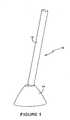
Figure 1 is a simplistic perspective view of the device in which the elongate column is shown moveably connected relative to a fixed support structure; -
Figure 2 is an enlarged perspective view of the support structure and the lower end of the column shown partially in vertical cross-section; -
Figure 3 is a further enlargement of the view shown inFigure 2 showing the base of the column and an array of hydraulicipiston and cylinder assemblies; -
Figure 4 is a still further enlarged view of the view of the base of the column showing annular banks of the piston and cylinder assemblies; -
Figure 5 is a perspective view of one mechanical arrangement for the actuation of the hydraulic piston and cylinder assemblies; -
Figure 5a is a sketch of the lower end of the device; -
Figure 6 is mechanical arrangement for transferring movement of the column into rotational movement to drive generators; -
Figure 7 is top view of the column showing movement as a result of vortex shedding; and -
Figure 8 is view similar tofigure 7 emphasising vortex induced eddies. - Referring first to
Figures 1 to 6 of the drawings, thedevice 10 comprises an elongatebuoyant column 12, which is received and journalled in asupport structure 14 adapted to be secured to the sea bed. It is envisaged that the column may have a length of the order of 200m and be of up to 40m in diameter. It is therefore a massive structure but may be formed from a suitable plastics material. - It is further envisaged that the
column 12 can be formed from a stack of modular sections of annular form. If the column is formed as a modular structure its height can be varied for different water depths. Moreover, although this structure is non-intrusive when installed, it readily can be repaired if damaged by impact. - The column is journalled in the support structure by means of a ball and socket joint adjacent the upper end of the support structure. The ball and socket joint comprises a spherical portion 16 (
Figures 2 and4 ) of the column adjacent its lower extremity and aconcave annulus 18 formed in the support structure. Thus, the column can move universally relative to the support structure automatically in response to force transmitted by the various complex movements of the ocean. However, the overall movement of the column is limited by shaped complementary mating bearing surfaces 20, 22 provided by the column and thehead 24 of the support structure, respectively. - The extremity of the supported end of the column is formed with a
spherical actuator 26 which is spaced from thespherical portion 16 by anintegral arm 28. Thespherical actuator 26 operates within asemi-spherical bowl 30 formed within the support structure. Thespherical actuator 30 rides around protruding spheres which actuate the pistons in anarray 32 of piston and cylinder assemblies. The pistons are actuated in random sequence consequent upon the movement of the column. As shown, and best seen inFigures 3 and4 the array of piston and cylinder assemblies are arranged in thebowl 30 in a number of concentric annular banks, e.g. 34, 36, 38. The piston and cylinder assemblies are connected by suitable hydraulic and/or pneumatic circuits to a number ofelectrical power generators 40 which are housed in achamber 42 of the support structure disposed below thebowl 30. The actuation of the pistons and the connecting fluidic circuitry is such that continuous generation of electrical power is obtained through the constant motion of the column. However, it is envisaged that the electrical power generating means may be housed separately from the support structure and may be located on-shore so that the device pumps hydraulic fluid, which could be sea water, to energy accumulators for the remote generation of electricity. - Referring now to
Figure 5 of the drawings details one embodiment of a single piston andcylinder assembly 44 of thearray 32 is shown. The piston andcylinder assembly 44 comprises a housing in the form of acylindrical sleeve 46, each of which is contained in bores formed in thesemi-spherical bowl 30. One end of thesleeve 46 provides a seat for a spherical force transmission element, which preferably is aball 48.Ball 48 can rotate relative to thesleeve 46 and move axially within it, but is constrained from being dislodged from the open top of the sleeve by an inwardly directedlip 47. Thespherical actuator 26 at the supported end of thecolumn 12 periodically bears down on each of thetransmission balls 48 as the spherical actuator passes over them and depresses the transmission ball against a compression spring into the sleeve. The transmission ball abuts aspherical end 50 of apiston rod 52 of ahydraulic ram 54. Thus, axial movement of thetransmission ball 48 down thesleeve 46 depresses the piston rod against the force of areturn spring 56 to operate the piston of the hydraulic ram. The hydraulic ram causes hydraulic fluid to be transferred to an accumulator means which, in turn, drives one or more electrical generators. When thespherical actuator 26 is out of contact with that particular piston and cylinder assembly, the transmission ball returns to its upper inactive position at the top end of the sleeve by the restorative force of thereturn spring 56. - Referring now to
Figure 6 of the drawings, another embodiment of piston and cylinder assembly is shown, and like parts to those ofFigure 5 are designated like reference numerals, with the addition of suffix 'a' and function in a similar manner. - In this alternative embodiment, the piston and
cylinder assembly 44a does not involve the inclusion of hydraulic or pneumatic components but rather is a mechanical assembly. Thus, thepiston rod 52a reciprocates withinsleeve 46a, against the force ofreturn spring 56a, and protrudes through anopening 58 formed in anend wall 60 of the sleeve. The exposed lower end of the piston rod is formed with anaxial gear 62 which meshes with and drives planet gear wheel 64 in consequence of reciprocal movement of thepiston rod 52a. Gear 64 meshes with and drives asun drive gear 66 of an electrical generator to produce electrical power. -
Figures 7 and 8 of the drawings illustrate the phenomena of vortex shedding to which the buoyant column is subject when disposed in a fluid flow. - The buoyant column is designed to extract energy from tidal flows of 2 -6 m/s, and is caused to oscillate from side to side by the process of vortex shedding.

- The following equation applies to the frequency of oscillations due to vortex shedding, but this may be perturbed if the oscillations are damped.

- Where Re is the Reynold's number and

- υ = water.vis cos ity = 0.001Pa.s
- ρ = water.density =1025kg / m3
- d = device.diameter
- u∞ = water.velocity
- h = deviceheight
- f = frequency
- T = period
- CL = liftcoefficient = 1to3.5
- If the buoyant column swings by θ radians then the work done or energy is E = Γθ J (Joules)
- The power is then P = E/T or P = Ef J/s or W
- Substituting from all of the above


- To estimate the available power in the water flow, the power is based on standard energy flux and area, with the area being the frontage area of the device (hd). This is very much an estimate, and it may be that in reality it is smaller, or on the other hand , it may be larger as the area swept out by the device may be the real area ie 2hθ.

- But we can take A=dh and so

- The conversion efficiency will therefore be


- The above calculations are used to obtain some numerical values, to some extent subject to a number of uncertainties.
- The following calculations are for a column length of 200m from pivot to water surface. The column diameter varies from 5 to 40m, and the water velocity runs up to 6m/s.
-

- The energy captured in each cycle is strongly dependent on device diameter and water velocity.
- The period of vortex induced oscillations is shown below, and is also strongly dependent on device diameter and water velocity.

- Computing the cycle power is then achieved by dividing the cycle energy by the period, and this has the important outcome of reducing all of the curves for column diameter onto the same power curve. This occurs because increasing the column diameter increases the energy in each cycle but since the oscillation period increases in line with this, the overall effect on power output is that it is independent of diameter. On the scale below 2.00E+07 means 20MW.

- It is possible to estimate the efficiency by considering the output power relative to the power in the water flow. This has a number of uncertainties and may be of little value, but the trend shown suggests that the efficiency is better at lower device diameters.
- The single curve applies to all water velocities.

- Small scale model tests have been conducted in a flume tank and load/displacement measurements were made subsequently.
- Assuming the model to be at a scale of 1:600, ( 0.33m :200m), then using Froude scaling, the flow in the tank, which was variously 10,20,30,40 litres per second, corresponded to a velocity of 2.7, 5.4, 8.2 and 10.8 m/s respectively.
- The load/displacement measurement result of 15N for the force corresponds to 15*6003 = 3.24GN
- If the column swings through 15 degrees then the Energy = 848 MJ
- From the tank test results the period of motion was of the order of 1s, which corresponds to a full scale period of 1 * 6000.5 = 24.49 s
- The full scale power will therefore be 848 MJ/24.49s = 34 MW
- The maths and small scale tests show the potential for the concept. The body moves in the manner predicted and on the basis of many assumptions output power levels of 10's of MW are estimated. A full scale device of 200m, and any diameter from 5 to 40 m might produce 50MW in water velocities of 6m/s.
- The assumptions of effective surface area, lift coefficient, vortex mechanism, influence of damping, swept area etc could be refined, and yield superior performance. A lift coefficient of 1 was used in the present calculations, whereas it might be as high as 3.5 , which would give a direct improvement of a factor of 3.5. On the other hand efficiencies are unlikely to exceed 0.59 (59%) as this is a theoretical limit in open flow according to Lanchester-Betz criterion.
- It is also envisaged within the scope of the present invention that the device could be installed in an inverted attitude so that the column is suspended from the support structure in a body of water. In such an arrangement the lower free end of the column would be weighted and would act like a pendulum with universal motion. The support structure itself would be supported by a gantry spanning a natural or man-made channel through which water flows or the gantry could span the banks of a river.
- In a still further embodiment of the invention, it is envisaged that the device could be modified for use as a wind powered device. In this arrangement the column could be formed from a light weight fabric, plastics or other suitable material providing a sealed buoyant cylinder filled with air or helium.
 | Then  |
| The lift force due to the vortex is given by L = CL (0.5ρu2) per unit area. CL is uncertain in the vortex situation, but is probably between 1 and 3.5. A value of 1.0 is used here. | |
| Consider a band 1 metre thick, a distance "y" metres above the fulcrum, then the total force from this band is taken to be the lift force * 0.5 *diameter G = CL 0.5d. Assuming half of the diameter is the area over which the lift occurs. | |
| The torque due to the force G arising from this band is then τ = Gy | |
| The total torque on the device is obtained by integrating the effect of all bands from y=0 to y=h, this gives | |
| |
Claims (16)
- A power capture device (10) for utilising movement of a fluid body in use, the device comprises an elongate column (12) buoyant in a fluid to a biased orientation and in a journalled association adjacent to an extremity with a support structure (14) for universal movement thereabout defined by the journalled association, the support structure (14) being adapted to be fixed with the column (12) disposed in a fluid flow in use so that by its shape, position and length the column (12) experiences variable motion due to an induced vortex effect at the downstream side of the column (12) in the flow balanced by the buoyance of the column (12) to the biased orientation which creates universal motion relative to the support structure (14) due to fluid flow past the column (12) in use, wherein the device includes actuating means (30) to convert movement of the extremity of the column (12) to an operative force, the actuating means comprising means to engage parts of the extremity (26) beyond the journalled association to move and/or displace an actuator (30) as the extremity (26) of the column (12) moves to provide an operative force.
- A power capture device according to claim 1, wherein the buoyant column (12) is adapted to stand upright relative to the support structure (14).
- A power capture device according to claim 1, wherein the buoyant column (12) is adapted to be suspended from the support structure (14).
- A power capture device according to any of the preceding claims, wherein the support structure (14) is adapted to be secured to the bed or banks of a body of water, such as the sea bed or a river bed or bank and wherein the column (12) is disposed for at least partially submerged universal motion relative to the support structure (14) automatically in response to force transmitted by the flow of water past the column.
- A power capture device according to any of the preceding claims wherein the aetuating means comprise a plurality of piston and cylinder assemblies (32).
- A power capture device according to claims 5, wherein an array of piston and cylinder assemblies (32) is provided by the support structure (14), and wherein the column (12) is adapted to actuate the piston and cylinder assemblies (32) in random sequence as a result of movement of the column relative (12) to the support structure (14).
- A power capture device according to claim 6, wherein the array of piston and cylinder assemblies (32) are disposed to present means to actuate the heads of the pistons to the supported end (28) of the column (12) which causes reciprocal movement of the pistons in random sequence as a result of said movement of the column.
- A power capture device according to claim 7, wherein the array of piston and cylinder assemblies (32) are disposed in a part spherical arrangement and the supported end of the column (28) includes a spherical actuator which rides around the part spherical arrangement of the piston and cylinder assemblies (32) to cause said reciprocal movement of the pistons in random sequence.
- A power capture device according to claim 8, wherein the piston and cylinder assemblies are arranged in a plurality of concentric annular banks (34, 36, 38) within a part spherical recess within the support structure.
- A power capture device according to any of claims 6 to 9, wherein the array of piston and cylinder assemblies (32) are hydraulically or pneumatically connected to drive electrical power generating means (40) contained within the support structure (14).
- A power capture device according to any of claims 6 to 9, wherein the array of piston and cylinder assemblies (32) are mechanically actuated to drive electrical power generating means (40) contained within the support structure (14).
- A power capture device according to any of the preceding claims, wherein the column (12) is journalled in the support structure by means of a ball and socket joint arrangement (16, 18).
- A power capture device according to claim 12, wherein the supported end of the column includes the ball of the ball and socket joint arrangement (16, 18) and the socket of the ball and socket joint arrangement is provided by a concave annulus (18) within the support structure (14).
- A power capture device according to claim 13, wherein the column (12) includes an extension (28) within the support structure beyond the ball of the ball and socket joint arrangement (16, 18) which actuates said means in random sequence to drive electrical power generating means (40) as a result of movement of the column (12) relative to the support structure (14).
- A power capture device according to any of the preceding claims, wherein the support structure (14) and the column (12) have complementary formed faces (20, 22) to limit the universal movement of the column (12) relative to the support structure (14).
- A power capture device according to any of the preceding claims wherein the column comprises a stack of buoyant modular sections.
Applications Claiming Priority (2)
| Application Number | Priority Date | Filing Date | Title |
|---|---|---|---|
| GBGB0903272.3A GB0903272D0 (en) | 2009-02-26 | 2009-02-26 | Ocean based power generating device |
| PCT/GB2010/050319 WO2010097622A2 (en) | 2009-02-26 | 2010-02-25 | A power capture device |
Publications (2)
| Publication Number | Publication Date |
|---|---|
| EP2401496A2 EP2401496A2 (en) | 2012-01-04 |
| EP2401496B1 true EP2401496B1 (en) | 2014-10-08 |
Family
ID=40565757
Family Applications (1)
| Application Number | Title | Priority Date | Filing Date |
|---|---|---|---|
| EP10711250.0A Not-in-force EP2401496B1 (en) | 2009-02-26 | 2010-02-25 | A power capture device |
Country Status (10)
| Country | Link |
|---|---|
| US (1) | US8584454B2 (en) |
| EP (1) | EP2401496B1 (en) |
| JP (1) | JP2012518752A (en) |
| KR (1) | KR20110137785A (en) |
| AU (1) | AU2010217391A1 (en) |
| CA (1) | CA2790889A1 (en) |
| DK (1) | DK2401496T3 (en) |
| GB (2) | GB0903272D0 (en) |
| HK (1) | HK1165844A1 (en) |
| WO (1) | WO2010097622A2 (en) |
Families Citing this family (5)
| Publication number | Priority date | Publication date | Assignee | Title |
|---|---|---|---|---|
| DK177654B1 (en) * | 2012-06-20 | 2014-02-03 | Subcpartner Holding Aps | WAVE POWER CONVERTER |
| EP2832987B1 (en) * | 2013-08-02 | 2016-01-06 | King Abdulaziz City for Science & Technology (KACST) | Energy generation device and energy harvesting device comprising the same |
| GB2579850B (en) * | 2018-12-18 | 2021-05-19 | Subsea 7 Norway As | Long-distance transmission of power underwater |
| CN111577515A (en) * | 2020-05-13 | 2020-08-25 | 中国船舶工业系统工程研究院 | Gyro inertia wave energy stabilization power generation device |
| IL310726A (en) * | 2021-08-11 | 2024-04-01 | Global Turbulence Ltd | System and method for generation of electricity from wind energy |
Family Cites Families (4)
| Publication number | Priority date | Publication date | Assignee | Title |
|---|---|---|---|---|
| US4196591A (en) * | 1978-02-01 | 1980-04-08 | Robert L. Busselman | Wave powered energy generator |
| JP2001157433A (en) * | 1999-11-26 | 2001-06-08 | Fujitsu Ltd | Vibration power-generating device by fluid |
| DE20201389U1 (en) * | 2001-12-17 | 2002-05-23 | Ranz Klaus Guenter | Flow pendulum power plant |
| GB2428747B (en) * | 2005-08-02 | 2009-10-21 | Seawood Designs Inc | Wave energy conversion system |
-
2009
- 2009-02-26 GB GBGB0903272.3A patent/GB0903272D0/en not_active Ceased
- 2009-06-09 GB GBGB0909881.5A patent/GB0909881D0/en not_active Ceased
-
2010
- 2010-02-25 KR KR1020117022517A patent/KR20110137785A/en not_active Application Discontinuation
- 2010-02-25 AU AU2010217391A patent/AU2010217391A1/en not_active Abandoned
- 2010-02-25 WO PCT/GB2010/050319 patent/WO2010097622A2/en active Application Filing
- 2010-02-25 US US12/991,117 patent/US8584454B2/en not_active Expired - Fee Related
- 2010-02-25 CA CA2790889A patent/CA2790889A1/en not_active Abandoned
- 2010-02-25 JP JP2011551527A patent/JP2012518752A/en active Pending
- 2010-02-25 EP EP10711250.0A patent/EP2401496B1/en not_active Not-in-force
- 2010-02-25 DK DK10711250.0T patent/DK2401496T3/en active
-
2012
- 2012-07-04 HK HK12106489.1A patent/HK1165844A1/en not_active IP Right Cessation
Also Published As
| Publication number | Publication date |
|---|---|
| WO2010097622A2 (en) | 2010-09-02 |
| CA2790889A1 (en) | 2010-09-02 |
| KR20110137785A (en) | 2011-12-23 |
| GB0909881D0 (en) | 2009-07-22 |
| US20110173967A1 (en) | 2011-07-21 |
| HK1165844A1 (en) | 2012-10-12 |
| JP2012518752A (en) | 2012-08-16 |
| EP2401496A2 (en) | 2012-01-04 |
| US8584454B2 (en) | 2013-11-19 |
| GB0903272D0 (en) | 2009-04-08 |
| DK2401496T3 (en) | 2015-01-19 |
| AU2010217391A1 (en) | 2011-10-20 |
| WO2010097622A3 (en) | 2011-04-14 |
Similar Documents
| Publication | Publication Date | Title |
|---|---|---|
| US7339285B2 (en) | Hydroelectric wave-energy conversion system | |
| Mustapa et al. | Wave energy device and breakwater integration: A review | |
| US7199481B2 (en) | Wave energy conversion system | |
| CN101589223B (en) | A completely submerged wave energy converter | |
| US20120032444A1 (en) | Wave Catcher | |
| JP2008536045A (en) | Equipment equipped with wave power device and its support structure | |
| Prakash et al. | Wave energy converter: a review of wave energy conversion technology | |
| AU2010315193A1 (en) | Wave energy conversion device | |
| EP1036274A1 (en) | A wave energy converter | |
| EP2401496B1 (en) | A power capture device | |
| WO1998032967A1 (en) | Wave energy converter | |
| GB2414771A (en) | A wave power generator apparatus | |
| Aubry et al. | Wave energy converters | |
| US11441532B2 (en) | Submerged oscillating water column energy harvester | |
| Clare et al. | HARNESSING SEA WAVE ENERGY BY A SUBMERGED CYLINDER DEVICE. | |
| Sundar et al. | Wave Energy Convertors | |
| CN109274288A (en) | A kind of floatation type has the piezoelectricity Wave energy converting device of slide link mechanism | |
| Jayathunga et al. | Development and Performance Analysis of a Small-Scale On-shore Wave Energy Converter | |
| Wimmler et al. | Assessing offshore renewable energy technologies based on natural conditions and site characteristics | |
| Suwanapingkarl et al. | Reviews Existing Technologies and Proposes ‘E8-PowerBuoys' Nano-Scale Generator Of Tidal And Wave Energy For River And Ocean | |
| US20080217919A1 (en) | Renewable energy wave air pump | |
| TR201608214A2 (en) | System for Generating Electricity from Sea and Ocean Waves | |
| Muzib | Modeling Annual Energy Production of a Point Absorber Wave Energy Converter for the Great Lakes | |
| Thomas et al. | WAVE ENERGY CONVERTERS: COMPARISON & DESIGN ASPECTS | |
| Prakash et al. | Wave Energy Converter |
Legal Events
| Date | Code | Title | Description |
|---|---|---|---|
| PUAI | Public reference made under article 153(3) epc to a published international application that has entered the european phase |
Free format text: ORIGINAL CODE: 0009012 |
|
| 17P | Request for examination filed |
Effective date: 20110926 |
|
| AK | Designated contracting states |
Kind code of ref document: A2 Designated state(s): AT BE BG CH CY CZ DE DK EE ES FI FR GB GR HR HU IE IS IT LI LT LU LV MC MK MT NL NO PL PT RO SE SI SK SM TR |
|
| DAX | Request for extension of the european patent (deleted) | ||
| RAP1 | Party data changed (applicant data changed or rights of an application transferred) |
Owner name: LISSAJOUS ENERGY LLP |
|
| 17Q | First examination report despatched |
Effective date: 20120831 |
|
| REG | Reference to a national code |
Ref country code: HK Ref legal event code: DE Ref document number: 1165844 Country of ref document: HK |
|
| REG | Reference to a national code |
Ref country code: DE Ref legal event code: R079 Ref document number: 602010019376 Country of ref document: DE Free format text: PREVIOUS MAIN CLASS: F03B0013180000 Ipc: F03B0013080000 |
|
| RIC1 | Information provided on ipc code assigned before grant |
Ipc: F03B 13/08 20060101AFI20131127BHEP Ipc: F03G 7/08 20060101ALI20131127BHEP Ipc: F03B 13/26 20060101ALI20131127BHEP Ipc: F03B 13/20 20060101ALI20131127BHEP Ipc: F03B 13/18 20060101ALI20131127BHEP |
|
| GRAP | Despatch of communication of intention to grant a patent |
Free format text: ORIGINAL CODE: EPIDOSNIGR1 |
|
| INTG | Intention to grant announced |
Effective date: 20140108 |
|
| GRAS | Grant fee paid |
Free format text: ORIGINAL CODE: EPIDOSNIGR3 |
|
| GRAA | (expected) grant |
Free format text: ORIGINAL CODE: 0009210 |
|
| AK | Designated contracting states |
Kind code of ref document: B1 Designated state(s): AT BE BG CH CY CZ DE DK EE ES FI FR GB GR HR HU IE IS IT LI LT LU LV MC MK MT NL NO PL PT RO SE SI SK SM TR |
|
| REG | Reference to a national code |
Ref country code: GB Ref legal event code: FG4D |
|
| REG | Reference to a national code |
Ref country code: AT Ref legal event code: REF Ref document number: 690787 Country of ref document: AT Kind code of ref document: T Effective date: 20141015 Ref country code: CH Ref legal event code: EP |
|
| REG | Reference to a national code |
Ref country code: IE Ref legal event code: FG4D |
|
| REG | Reference to a national code |
Ref country code: DE Ref legal event code: R096 Ref document number: 602010019376 Country of ref document: DE Effective date: 20141120 |
|
| REG | Reference to a national code |
Ref country code: DK Ref legal event code: T3 Effective date: 20150113 |
|
| REG | Reference to a national code |
Ref country code: SE Ref legal event code: TRGR |
|
| REG | Reference to a national code |
Ref country code: NL Ref legal event code: VDEP Effective date: 20141008 |
|
| REG | Reference to a national code |
Ref country code: AT Ref legal event code: MK05 Ref document number: 690787 Country of ref document: AT Kind code of ref document: T Effective date: 20141008 |
|
| REG | Reference to a national code |
Ref country code: NO Ref legal event code: T2 Effective date: 20141008 |
|
| REG | Reference to a national code |
Ref country code: LT Ref legal event code: MG4D |
|
| PG25 | Lapsed in a contracting state [announced via postgrant information from national office to epo] |
Ref country code: NL Free format text: LAPSE BECAUSE OF FAILURE TO SUBMIT A TRANSLATION OF THE DESCRIPTION OR TO PAY THE FEE WITHIN THE PRESCRIBED TIME-LIMIT Effective date: 20141008 |
|
| PG25 | Lapsed in a contracting state [announced via postgrant information from national office to epo] |
Ref country code: ES Free format text: LAPSE BECAUSE OF FAILURE TO SUBMIT A TRANSLATION OF THE DESCRIPTION OR TO PAY THE FEE WITHIN THE PRESCRIBED TIME-LIMIT Effective date: 20141008 Ref country code: IS Free format text: LAPSE BECAUSE OF FAILURE TO SUBMIT A TRANSLATION OF THE DESCRIPTION OR TO PAY THE FEE WITHIN THE PRESCRIBED TIME-LIMIT Effective date: 20150208 Ref country code: PT Free format text: LAPSE BECAUSE OF FAILURE TO SUBMIT A TRANSLATION OF THE DESCRIPTION OR TO PAY THE FEE WITHIN THE PRESCRIBED TIME-LIMIT Effective date: 20150209 Ref country code: FI Free format text: LAPSE BECAUSE OF FAILURE TO SUBMIT A TRANSLATION OF THE DESCRIPTION OR TO PAY THE FEE WITHIN THE PRESCRIBED TIME-LIMIT Effective date: 20141008 Ref country code: LT Free format text: LAPSE BECAUSE OF FAILURE TO SUBMIT A TRANSLATION OF THE DESCRIPTION OR TO PAY THE FEE WITHIN THE PRESCRIBED TIME-LIMIT Effective date: 20141008 |
|
| PG25 | Lapsed in a contracting state [announced via postgrant information from national office to epo] |
Ref country code: LV Free format text: LAPSE BECAUSE OF FAILURE TO SUBMIT A TRANSLATION OF THE DESCRIPTION OR TO PAY THE FEE WITHIN THE PRESCRIBED TIME-LIMIT Effective date: 20141008 Ref country code: GR Free format text: LAPSE BECAUSE OF FAILURE TO SUBMIT A TRANSLATION OF THE DESCRIPTION OR TO PAY THE FEE WITHIN THE PRESCRIBED TIME-LIMIT Effective date: 20150109 Ref country code: AT Free format text: LAPSE BECAUSE OF FAILURE TO SUBMIT A TRANSLATION OF THE DESCRIPTION OR TO PAY THE FEE WITHIN THE PRESCRIBED TIME-LIMIT Effective date: 20141008 Ref country code: PL Free format text: LAPSE BECAUSE OF FAILURE TO SUBMIT A TRANSLATION OF THE DESCRIPTION OR TO PAY THE FEE WITHIN THE PRESCRIBED TIME-LIMIT Effective date: 20141008 Ref country code: HR Free format text: LAPSE BECAUSE OF FAILURE TO SUBMIT A TRANSLATION OF THE DESCRIPTION OR TO PAY THE FEE WITHIN THE PRESCRIBED TIME-LIMIT Effective date: 20141008 Ref country code: CY Free format text: LAPSE BECAUSE OF FAILURE TO SUBMIT A TRANSLATION OF THE DESCRIPTION OR TO PAY THE FEE WITHIN THE PRESCRIBED TIME-LIMIT Effective date: 20141008 |
|
| PG25 | Lapsed in a contracting state [announced via postgrant information from national office to epo] |
Ref country code: BE Free format text: LAPSE BECAUSE OF NON-PAYMENT OF DUE FEES Effective date: 20150228 |
|
| REG | Reference to a national code |
Ref country code: DE Ref legal event code: R097 Ref document number: 602010019376 Country of ref document: DE |
|
| PG25 | Lapsed in a contracting state [announced via postgrant information from national office to epo] |
Ref country code: CZ Free format text: LAPSE BECAUSE OF FAILURE TO SUBMIT A TRANSLATION OF THE DESCRIPTION OR TO PAY THE FEE WITHIN THE PRESCRIBED TIME-LIMIT Effective date: 20141008 Ref country code: EE Free format text: LAPSE BECAUSE OF FAILURE TO SUBMIT A TRANSLATION OF THE DESCRIPTION OR TO PAY THE FEE WITHIN THE PRESCRIBED TIME-LIMIT Effective date: 20141008 Ref country code: RO Free format text: LAPSE BECAUSE OF FAILURE TO SUBMIT A TRANSLATION OF THE DESCRIPTION OR TO PAY THE FEE WITHIN THE PRESCRIBED TIME-LIMIT Effective date: 20141008 Ref country code: SK Free format text: LAPSE BECAUSE OF FAILURE TO SUBMIT A TRANSLATION OF THE DESCRIPTION OR TO PAY THE FEE WITHIN THE PRESCRIBED TIME-LIMIT Effective date: 20141008 |
|
| PLBE | No opposition filed within time limit |
Free format text: ORIGINAL CODE: 0009261 |
|
| STAA | Information on the status of an ep patent application or granted ep patent |
Free format text: STATUS: NO OPPOSITION FILED WITHIN TIME LIMIT |
|
| PG25 | Lapsed in a contracting state [announced via postgrant information from national office to epo] |
Ref country code: IT Free format text: LAPSE BECAUSE OF FAILURE TO SUBMIT A TRANSLATION OF THE DESCRIPTION OR TO PAY THE FEE WITHIN THE PRESCRIBED TIME-LIMIT Effective date: 20141008 |
|
| REG | Reference to a national code |
Ref country code: HK Ref legal event code: GR Ref document number: 1165844 Country of ref document: HK |
|
| 26N | No opposition filed |
Effective date: 20150709 |
|
| PG25 | Lapsed in a contracting state [announced via postgrant information from national office to epo] |
Ref country code: LU Free format text: LAPSE BECAUSE OF FAILURE TO SUBMIT A TRANSLATION OF THE DESCRIPTION OR TO PAY THE FEE WITHIN THE PRESCRIBED TIME-LIMIT Effective date: 20150225 |
|
| REG | Reference to a national code |
Ref country code: CH Ref legal event code: PL |
|
| PG25 | Lapsed in a contracting state [announced via postgrant information from national office to epo] |
Ref country code: LI Free format text: LAPSE BECAUSE OF NON-PAYMENT OF DUE FEES Effective date: 20150228 Ref country code: MC Free format text: LAPSE BECAUSE OF FAILURE TO SUBMIT A TRANSLATION OF THE DESCRIPTION OR TO PAY THE FEE WITHIN THE PRESCRIBED TIME-LIMIT Effective date: 20141008 Ref country code: CH Free format text: LAPSE BECAUSE OF NON-PAYMENT OF DUE FEES Effective date: 20150228 |
|
| REG | Reference to a national code |
Ref country code: IE Ref legal event code: MM4A |
|
| REG | Reference to a national code |
Ref country code: FR Ref legal event code: ST Effective date: 20151030 |
|
| PG25 | Lapsed in a contracting state [announced via postgrant information from national office to epo] |
Ref country code: IE Free format text: LAPSE BECAUSE OF NON-PAYMENT OF DUE FEES Effective date: 20150225 |
|
| PG25 | Lapsed in a contracting state [announced via postgrant information from national office to epo] |
Ref country code: FR Free format text: LAPSE BECAUSE OF NON-PAYMENT OF DUE FEES Effective date: 20150302 Ref country code: SI Free format text: LAPSE BECAUSE OF FAILURE TO SUBMIT A TRANSLATION OF THE DESCRIPTION OR TO PAY THE FEE WITHIN THE PRESCRIBED TIME-LIMIT Effective date: 20141008 |
|
| PG25 | Lapsed in a contracting state [announced via postgrant information from national office to epo] |
Ref country code: MT Free format text: LAPSE BECAUSE OF FAILURE TO SUBMIT A TRANSLATION OF THE DESCRIPTION OR TO PAY THE FEE WITHIN THE PRESCRIBED TIME-LIMIT Effective date: 20141008 |
|
| PG25 | Lapsed in a contracting state [announced via postgrant information from national office to epo] |
Ref country code: SM Free format text: LAPSE BECAUSE OF FAILURE TO SUBMIT A TRANSLATION OF THE DESCRIPTION OR TO PAY THE FEE WITHIN THE PRESCRIBED TIME-LIMIT Effective date: 20141008 Ref country code: BG Free format text: LAPSE BECAUSE OF FAILURE TO SUBMIT A TRANSLATION OF THE DESCRIPTION OR TO PAY THE FEE WITHIN THE PRESCRIBED TIME-LIMIT Effective date: 20141008 Ref country code: HU Free format text: LAPSE BECAUSE OF FAILURE TO SUBMIT A TRANSLATION OF THE DESCRIPTION OR TO PAY THE FEE WITHIN THE PRESCRIBED TIME-LIMIT; INVALID AB INITIO Effective date: 20100225 |
|
| PG25 | Lapsed in a contracting state [announced via postgrant information from national office to epo] |
Ref country code: TR Free format text: LAPSE BECAUSE OF FAILURE TO SUBMIT A TRANSLATION OF THE DESCRIPTION OR TO PAY THE FEE WITHIN THE PRESCRIBED TIME-LIMIT Effective date: 20141008 |
|
| PGFP | Annual fee paid to national office [announced via postgrant information from national office to epo] |
Ref country code: DE Payment date: 20170822 Year of fee payment: 8 Ref country code: NO Payment date: 20170824 Year of fee payment: 8 |
|
| PGFP | Annual fee paid to national office [announced via postgrant information from national office to epo] |
Ref country code: SE Payment date: 20170821 Year of fee payment: 8 Ref country code: DK Payment date: 20170821 Year of fee payment: 8 |
|
| PG25 | Lapsed in a contracting state [announced via postgrant information from national office to epo] |
Ref country code: MK Free format text: LAPSE BECAUSE OF FAILURE TO SUBMIT A TRANSLATION OF THE DESCRIPTION OR TO PAY THE FEE WITHIN THE PRESCRIBED TIME-LIMIT Effective date: 20141008 |
|
| REG | Reference to a national code |
Ref country code: DE Ref legal event code: R119 Ref document number: 602010019376 Country of ref document: DE |
|
| REG | Reference to a national code |
Ref country code: DK Ref legal event code: EBP Effective date: 20180228 Ref country code: NO Ref legal event code: MMEP |
|
| REG | Reference to a national code |
Ref country code: SE Ref legal event code: EUG |
|
| PG25 | Lapsed in a contracting state [announced via postgrant information from national office to epo] |
Ref country code: SE Free format text: LAPSE BECAUSE OF NON-PAYMENT OF DUE FEES Effective date: 20180226 Ref country code: NO Free format text: LAPSE BECAUSE OF NON-PAYMENT OF DUE FEES Effective date: 20180228 |
|
| PGFP | Annual fee paid to national office [announced via postgrant information from national office to epo] |
Ref country code: GB Payment date: 20180831 Year of fee payment: 9 |
|
| PG25 | Lapsed in a contracting state [announced via postgrant information from national office to epo] |
Ref country code: DK Free format text: LAPSE BECAUSE OF NON-PAYMENT OF DUE FEES Effective date: 20180228 Ref country code: DE Free format text: LAPSE BECAUSE OF NON-PAYMENT OF DUE FEES Effective date: 20180901 |
|
| GBPC | Gb: european patent ceased through non-payment of renewal fee |
Effective date: 20190225 |
|
| PG25 | Lapsed in a contracting state [announced via postgrant information from national office to epo] |
Ref country code: GB Free format text: LAPSE BECAUSE OF NON-PAYMENT OF DUE FEES Effective date: 20190225 |