EP4484657A1 - Improved swivel joint for work vehicle - Google Patents
Improved swivel joint for work vehicle Download PDFInfo
- Publication number
- EP4484657A1 EP4484657A1 EP24184175.8A EP24184175A EP4484657A1 EP 4484657 A1 EP4484657 A1 EP 4484657A1 EP 24184175 A EP24184175 A EP 24184175A EP 4484657 A1 EP4484657 A1 EP 4484657A1
- Authority
- EP
- European Patent Office
- Prior art keywords
- swivel joint
- chassis
- main body
- joint assembly
- work vehicle
- Prior art date
- Legal status (The legal status is an assumption and is not a legal conclusion. Google has not performed a legal analysis and makes no representation as to the accuracy of the status listed.)
- Pending
Links
Images


Classifications
-
- E—FIXED CONSTRUCTIONS
- E02—HYDRAULIC ENGINEERING; FOUNDATIONS; SOIL SHIFTING
- E02F—DREDGING; SOIL-SHIFTING
- E02F9/00—Component parts of dredgers or soil-shifting machines, not restricted to one of the kinds covered by groups E02F3/00 - E02F7/00
- E02F9/08—Superstructures; Supports for superstructures
- E02F9/10—Supports for movable superstructures mounted on travelling or walking gears or on other superstructures
- E02F9/12—Slewing or traversing gears
-
- E—FIXED CONSTRUCTIONS
- E02—HYDRAULIC ENGINEERING; FOUNDATIONS; SOIL SHIFTING
- E02F—DREDGING; SOIL-SHIFTING
- E02F9/00—Component parts of dredgers or soil-shifting machines, not restricted to one of the kinds covered by groups E02F3/00 - E02F7/00
- E02F9/20—Drives; Control devices
- E02F9/22—Hydraulic or pneumatic drives
- E02F9/2217—Hydraulic or pneumatic drives with energy recovery arrangements, e.g. using accumulators, flywheels
Definitions
- the present invention concerns a swivel joint for a work vehicle.
- the present invention finds its preferred, although not exclusive, application in earthmoving machines such as a scraper. Reference will be made to this application by way of example below.
- An aim of the present invention is to satisfy the above mentioned needs in a cost-effective and optimized manner.
- Figure 1 discloses a work vehicle 1 such as a scraper comprising a main body 2 and a chassis 4.
- the main body 2 may be provided with an operative element 3 such as a boom/bucket and the chassis 4 is movable on ground via ground engaging means 5 such as tracks.
- the main body 2 is carried by the chassis 4 in a movable manner, in particular rotatably carried about a vertical axis A.
- the operative system of the vehicle namely electric system and hydraulic system are connected between main body 2 and chassis 4 via swivel joint assembly 6.
- Swivel joint assembly 6 comprise a first element 6' and a second element rotatably 6" cooperating rotatably one with respect to the other in a fluid tight manner about the vertical axis A.
- the first element 6' and the second element 6" are fixedly carried to respectively one and another between the main body 2 and the chassis 4.
- first element 6' is fixedly carried by the main body 2 and a second element 6'' is fixedly carried by chassis 4.
- the first element 6' comprises a coupling portion 6a' configured to be fixed to the main body 2 and a plug portion 6b' extending from the coupling portion 6a' along the vertical axis A and having a cylindric shape.
- the second element 6" comprises a coupling portion 6a'' configured to be fixed to the chassis 4 and a housing portion 6b'' extending from the coupling portion 6a" along the vertical axis A and having a hollow cylindric shape configured to house therein the plug portion 6b' in a rotatably way about axis A in a fluid tight manner.
- the swivel joint assembly 6 is furthermore configured, as known, to define hydraulic passageways 7 and electric passageways 8 configured to allow connection between hydraulic and electric operative system between the chassis 4 and the main body 2.
- the second element 6'' is dimensioned to define a space 9 between the plug portion 6ba' of the first element 6' and the base portion 6a'' of the second element 6''.
- the space 9 is delimited radially by the housing portion 6b'' of the second element 6" and axially delimited between the plug portion 6ba' of the first element 6' and the base portion 6a'' of the second element 6' ' .
- the swivel joint assembly 6 comprises an electric machine 11 operationally interposed between the first and second elements 6', 6" and advantageously housed within space 9.
- the electric machine 11 is configured to generate electrical energy in function of the relative movement between the first and second elements 6', 6" in a first operation mode.
- the electric machine 11 can therefore act as a generator and comprise stator means 11' and rotor means 11'' respectively carried by one and another between the first and the second portions 6', 6''.
- stator means 11' are carried by the second element 6", namely by housing portion 6b'' and the rotor means 11'' are carried by the first element 6', i.e. by the plug portion 6b'.
- the electric machine 11 is then electrically connected via conductive means 12, such as wires, to electrical energy accumulator means (not shown) of the vehicle such as batteries.
- the swivel joint assembly 6 further comprise reduction means 13 housed within space 9 and operatively interposed between the first or second element 6', 6" and the electric machine 11 and configured to vary, i.e. multiply or reduce, the relative speed between the first and second elements 6', 6''.
- the reduction means 13 are interposed by plug portion 6b' of the first element 6' and the rotor means 11' of the electric machine 11.
- reduction means 13 comprises at least one gearing, such as a planetary gearing, configured to increase the speed between the one of the first/second elements 6', 6" and the electric machine 11.
- the main body 2 is moved with respect to the chassis 4 via actuator means 15, in particular hydraulic actuator means.
- Such electric actuator means 15 may comprise a hydraulic machine 15' and a rack 15" respectively carried by one and another between the main body 2 and the chassis 4.
- the hydraulic machine 15' is fixedly carried by the main body 2 and the rack 15" is realized fixedly to the chassis 4.
- the hydraulic machine 15' may rotate along rack 15" about a vertical axis A, i.e. coaxially to the rotation axis of the swivel joint assembly 6.
- the hydraulic machine 15' and the swivel joint assembly 6 are advantageously housed in a seat 16 dimensioned to allow the rotation of the actuator means 15 about the swivel joint assembly 6.
- the seat 16 is moreover configured to define the aforementioned rack 15" that may comprise teeth configured to cooperate with a gear carried by output shaft of the hydraulic machine 15'.
- the electric machine 11 may be further configured to assist the hydraulic machine 15' to improve movement between the first and second elements 6', 6" in a second operation mode, thereby using electrical energy in such case.
- decoupling means such as clutch means or free wheel means configured to allow the selective connection of the electric machine 11, in the disclosed embodiment of rotor 11 to plug portion 6b', in function of the operation of the actuators 15 in order to reduce the inertia due to the presence of electric machine 11 itself.
- the hydraulic machine 15' is controlled to allow rotation of main body 2 with respect to chassis 4 by cooperating with rack 15''.
- the hydraulic machine 15' provides a torque to its output gear to allow rotation of the main body of rack 15".
- the electric machine 11 of the swivel joint assembly 6 generates electrical energy from the free deceleration movement of main body 2 (due to its inertia) with respect to chassis 4.
- the hydraulic machine 15' may need a boost to allow quick turn of the main body 2.
- the electric machine 11 of the swivel joint assembly 6 is controlled to use electrical energy to assist the hydraulic machine 15'.
- the presence of reduction means 13 allows to vary the rotational speed of rotor 11" with respect to the speed of the main body 2 thereby increasing the production of electrical energy or reducing its consumption according to the above two operational modes.
- the proposed swivel joint assembly it is possible to integrate an electric machine in the swivel joint assembly to generate electrical energy for recovery the energy due to the free deceleration movement between the main body and the chassis thereby increasing the overall efficiency of the work vehicle or to substitute existing actuator means to move the main body with respect to chassis.
- the proposed solution does not foresees excessive modifications to existing layouts, therefore can be applied also to existing vehicles with small modifications.
- the presence of the electric machine in the swivel joint assembly guides the deceleration between main body and chassis thereby providing a smooth movement between these latter.
- actuator means it is possible to boost the movement of the main body with respect to the chassis, thereby providing smaller actuators and therefore further increasing the efficiency of the work vehicle.
- the disclosed structure may be inverted, i.e. with the plug portion fixedly carried by chassis and the housing portion fixedly carried by main body.
- the electrical machine may be external with respect to the housing defined by the elements of swivel joint and similarly, if present, reduction means may be placed differently and realized on any typology.
Landscapes
- Engineering & Computer Science (AREA)
- Mining & Mineral Resources (AREA)
- Civil Engineering (AREA)
- General Engineering & Computer Science (AREA)
- Structural Engineering (AREA)
- Component Parts Of Construction Machinery (AREA)
Abstract
Swivel joint assembly (6) for a work vehicle (1) comprising a main body (2) and a chassis (4) wherein the main body (2) is rotatably carried by the chassis (4) about a rotation axis (A), the swivel joint assembly (6) comprising a first element (6') configured to be fixed to one between main body (2) and chassis (4) and a second element (6'') configured to be fixed to the other between main body (2) and chassis (4) and cooperate at sliding with the first element (6') about the rotation axis (A), the swivel joint assembly (6) comprising an electric machine (11) operatively connected to the first and second elements (6', 6").
Description
- The present invention concerns a swivel joint for a work vehicle.
- The present invention finds its preferred, although not exclusive, application in earthmoving machines such as a scraper. Reference will be made to this application by way of example below.
- Work vehicles tends more and more to be electrified in order to reduce their pollutive emissions due to internal combustion engine. Therefore, electrical machines are used for substituting operations usually carried by torque provided by internal combustion engine.
- Clearly, electrical machines use electrical energy and therefore the need to provide accumulator means to allow energy accumulation to be used by electric machines.
- However, the need is felt to improve the efficiency of the overall work vehicle by either reducing the energy consumption of the electric machines, their dimension and the space used in the vehicle or by improving the capability of this latter to recovery energy.
- An aim of the present invention is to satisfy the above mentioned needs in a cost-effective and optimized manner.
- The aforementioned aim is reached by an energy recovery system and a work vehicle as claimed in the appended set of claims.
- For a better understanding of the present invention, a preferred embodiment is described in the following, by way of a non-limiting example, with reference to the attached drawings wherein:
-
Figure 1 is a perspective view of a work vehicle comprising a recovery system according to the invention; -
Figure 2 is an exploded perspective view of the work vehicle ofFigure 1 ; -
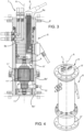
Figure 3 is a cross-sectional view along a longitudinal plane of a recovery system according to a first embodiment of the invention; -
Figure 4 is a perspective view of the recovery system according to the invention; and -
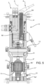
Figure 5 is a cross-sectional view along a longitudinal plane of a recovery system according to a second embodiment of the invention. -
Figure 1 discloses a work vehicle 1 such as a scraper comprising amain body 2 and achassis 4. Themain body 2 may be provided with anoperative element 3 such as a boom/bucket and thechassis 4 is movable on ground viaground engaging means 5 such as tracks. - As depicted in
figures 1 and2 themain body 2 is carried by thechassis 4 in a movable manner, in particular rotatably carried about a vertical axis A. The operative system of the vehicle, namely electric system and hydraulic system are connected betweenmain body 2 andchassis 4 via swiveljoint assembly 6. - Swivel
joint assembly 6 comprise a first element 6' and a second element rotatably 6" cooperating rotatably one with respect to the other in a fluid tight manner about the vertical axis A. The first element 6' and thesecond element 6" are fixedly carried to respectively one and another between themain body 2 and thechassis 4. - In
figures 3 and5 it is disclosed an exemplarily embodiment wherein the first element 6' is fixedly carried by themain body 2 and a second element 6'' is fixedly carried bychassis 4. - In both embodiment the first element 6' comprises a
coupling portion 6a' configured to be fixed to themain body 2 and aplug portion 6b' extending from thecoupling portion 6a' along the vertical axis A and having a cylindric shape. - The
second element 6" comprises acoupling portion 6a'' configured to be fixed to thechassis 4 and ahousing portion 6b'' extending from thecoupling portion 6a" along the vertical axis A and having a hollow cylindric shape configured to house therein theplug portion 6b' in a rotatably way about axis A in a fluid tight manner. - The
swivel joint assembly 6 is furthermore configured, as known, to definehydraulic passageways 7 andelectric passageways 8 configured to allow connection between hydraulic and electric operative system between thechassis 4 and themain body 2. - In particular, the second element 6'' is dimensioned to define a
space 9 between the plug portion 6ba' of the first element 6' and thebase portion 6a'' of the second element 6''. For sake of clarity, thespace 9 is delimited radially by thehousing portion 6b'' of thesecond element 6" and axially delimited between the plug portion 6ba' of the first element 6' and thebase portion 6a'' of the second element 6' ' . - According to the invention, the
swivel joint assembly 6 comprises anelectric machine 11 operationally interposed between the first andsecond elements 6', 6" and advantageously housed withinspace 9. - In detail, the
electric machine 11 is configured to generate electrical energy in function of the relative movement between the first andsecond elements 6', 6" in a first operation mode. - The
electric machine 11 can therefore act as a generator and comprise stator means 11' and rotor means 11'' respectively carried by one and another between the first and the second portions 6', 6''. - In both the disclosed exemplarily embodiments, the stator means 11' are carried by the
second element 6", namely byhousing portion 6b'' and the rotor means 11'' are carried by the first element 6', i.e. by theplug portion 6b'. - The
electric machine 11 is then electrically connected via conductive means 12, such as wires, to electrical energy accumulator means (not shown) of the vehicle such as batteries. - In the second embodiment of
figure 5 , the swiveljoint assembly 6 further comprise reduction means 13 housed withinspace 9 and operatively interposed between the first orsecond element 6', 6" and theelectric machine 11 and configured to vary, i.e. multiply or reduce, the relative speed between the first and second elements 6', 6''. - In the disclosed exemplarily embodiment of
figure 5 , the reduction means 13 are interposed byplug portion 6b' of the first element 6' and the rotor means 11' of theelectric machine 11. - In particular, even if not shown and detail, reduction means 13 comprises at least one gearing, such as a planetary gearing, configured to increase the speed between the one of the first/
second elements 6', 6" and theelectric machine 11. - Advantageously, the
main body 2 is moved with respect to thechassis 4 via actuator means 15, in particular hydraulic actuator means. Such electric actuator means 15 may comprise a hydraulic machine 15' and arack 15" respectively carried by one and another between themain body 2 and thechassis 4. In the disclosed embodiment, the hydraulic machine 15' is fixedly carried by themain body 2 and therack 15" is realized fixedly to thechassis 4. - In particular, the hydraulic machine 15' may rotate along
rack 15" about a vertical axis A, i.e. coaxially to the rotation axis of theswivel joint assembly 6. Accordingly, the hydraulic machine 15' and theswivel joint assembly 6 are advantageously housed in aseat 16 dimensioned to allow the rotation of the actuator means 15 about theswivel joint assembly 6. - The
seat 16 is moreover configured to define theaforementioned rack 15" that may comprise teeth configured to cooperate with a gear carried by output shaft of the hydraulic machine 15'. - In detail, the
electric machine 11 may be further configured to assist the hydraulic machine 15' to improve movement between the first andsecond elements 6', 6" in a second operation mode, thereby using electrical energy in such case. - Furthermore, it may be possible to provide decoupling means such as clutch means or free wheel means configured to allow the selective connection of the
electric machine 11, in the disclosed embodiment ofrotor 11 toplug portion 6b', in function of the operation of theactuators 15 in order to reduce the inertia due to the presence ofelectric machine 11 itself. - The operation of the embodiment of the invention as described above is the following.
- In both embodiments, the hydraulic machine 15' is controlled to allow rotation of
main body 2 with respect tochassis 4 by cooperating with rack 15''. In particular, the hydraulic machine 15' provides a torque to its output gear to allow rotation of the main body ofrack 15". In order to allow deceleration, when the correct position is going to be reached, theelectric machine 11 of theswivel joint assembly 6 generates electrical energy from the free deceleration movement of main body 2 (due to its inertia) with respect tochassis 4. - In a further operational mode, the hydraulic machine 15' may need a boost to allow quick turn of the
main body 2. In such case theelectric machine 11 of theswivel joint assembly 6 is controlled to use electrical energy to assist the hydraulic machine 15'. - In particular, in the embodiment of
figure 5 , the presence of reduction means 13 allows to vary the rotational speed ofrotor 11" with respect to the speed of themain body 2 thereby increasing the production of electrical energy or reducing its consumption according to the above two operational modes. - In view of the foregoing, the advantages of a recovery system and a work vehicle according to the invention are apparent.
- Thanks to the proposed swivel joint assembly, it is possible to integrate an electric machine in the swivel joint assembly to generate electrical energy for recovery the energy due to the free deceleration movement between the main body and the chassis thereby increasing the overall efficiency of the work vehicle or to substitute existing actuator means to move the main body with respect to chassis.
- The proposed solution, furthermore, does not foresees excessive modifications to existing layouts, therefore can be applied also to existing vehicles with small modifications.
- Moreover, the presence of the electric machine in the swivel joint assembly guides the deceleration between main body and chassis thereby providing a smooth movement between these latter.
- Otherwise, if provided with actuator means, it is possible to boost the movement of the main body with respect to the chassis, thereby providing smaller actuators and therefore further increasing the efficiency of the work vehicle.
- It is clear that modifications can be made to the described recovery system and a work vehicle which do not extend beyond the scope of protection defined by the claims.
- For example, the disclosed structure may be inverted, i.e. with the plug portion fixedly carried by chassis and the housing portion fixedly carried by main body.
- Moreover, different typology of electrical machines and their fixation may be present. For instance the electrical machine may be external with respect to the housing defined by the elements of swivel joint and similarly, if present, reduction means may be placed differently and realized on any typology.
- Clearly the typology of work vehicle, its shape and the proposed arrangement of actuators between main body and chassis may vary.
Claims (15)
- Swivel joint assembly (6) for a work vehicle (1) comprising a main body (2) and a chassis (4) wherein the main body (2) is rotatably carried by the chassis (4) about a rotation axis (A), the swivel joint assembly (6) comprising a first element (6') configured to be fixed to one between said main body (2) and said chassis (4) and a second element (6'') configured to be fixed to the other between said main body (2) and said chassis (4) and cooperate at sliding with said first element (6') about said rotation axis (A), said swivel joint assembly (6) comprising an electric machine (11) operatively connected to said first and second elements (6', 6").
- Swivel joint assembly according to claim 1, wherein said electric machine (11) is configured to generate electrical energy in function of the relative rotational displacement between said first and second elements (6', 6").
- Swivel joint assembly according to claim 1, wherein said electric machine (11) is configured to use electrical energy to move relatively one with respect to the other said first and second elements (6', 6").
- Swivel joint assembly according to any of the preceding claims, wherein said electric machine (11) comprises a rotor (11'') carried by one between said first and second elements (6', 6") and a stator (11') carried by the other between said first and second elements (6', 6").
- Swivel joint assembly according to any of the preceding claims, wherein said first element (6') comprises a base portion (6a') configured to be fixedly carried by said one between said main body (2) and said chassis (4) and a plug portion (6b') extending along said rotation axis (A) from said base portion (6a') and wherein said second element (6") comprises a base portion (6a") configured to be fixedly carried by said other between said main body (2) and said chassis (4) and a housing portion (6b'') extending along said rotation axis (A) from said base portion (6a") and dimensioned to house in sliding and fluid tight manner said plug portion (6b'), said housing portion (6b'') defining with said plug portion (6b') a space (9), said electric machine (11) being housed within said space (9).
- Swivel joint assembly according to claim 5, further comprising conductive means (12) configured to electrically connect said electric machine (11) to electric accumulator means of said work vehicle (1).
- Swivel joint assembly according to any of the preceding claims, further comprising reduction means (13) operatively interposed between said first and second elements (6', 6") and said electric machine (11) and configured to vary the rotation speed provided to the electric machine (11) with the respect to relative rotation speed between said first and second elements (6', 6").
- Swivel joint assembly according to claims 5 and 7, wherein said reduction means (13) are housed within said space (9) .
- Swivel joint assembly according to any of the preceding claims, wherein said first and second elements (6', 6'') define electric and hydraulic passageways (7, 8).
- Work vehicle (1) comprising a main body (2) and a chassis (4) movable on ground, said main body (2) being rotatably carried by said chassis (4) about a rotation axis (A), said work vehicle (1) comprising actuator means (15) for displacing said main body (2) with respect to said chassis (4) about said rotation axis (A) and a swivel joint assembly (6) for connecting operative hydraulic and/or electric systems between said chassis (4) and said main body (2), said swivel joint assembly (6) being realized according to any according to the preceding claims.
- Work vehicle according to claim 10, wherein said actuator means (15) comprise a hydraulic machine (15') carried by one between said main body (2) and said chassis (4) and operatively cooperating with a rack (15'') carried by the other between said main body (2) and said chassis (4).
- Work vehicle according to claim 10, wherein, in use, said hydraulic machine (15') moves about said rotation axis (A) about said swivel joint assembly (6).
- Work vehicle according to claim 10 or 11, wherein said actuator means (15) and said swivel joint assembly (6) are both housed in a seat (16) realized in the other between said main body (2) and said chassis (4), said seat (16) defining said rack (15").
- Work vehicle according to any of claims 9 to 12, further comprising decoupling means configured to allow the selective connection of said electric machine (11) to said first and/or second elements (6', 6") in function of the operation of said hydraulic machine (15').
- Work vehicle according to any of claims 10 to 13, wherein said electric machine (11) is configured to assist the between said first and second elements (6', 6") in addition to the action of said actuator means (15).
Applications Claiming Priority (1)
| Application Number | Priority Date | Filing Date | Title |
|---|---|---|---|
| IT102023000013566A IT202300013566A1 (en) | 2023-06-29 | 2023-06-29 | IMPROVED ROTARY JOINT FOR WORK VEHICLE |
Publications (1)
| Publication Number | Publication Date |
|---|---|
| EP4484657A1 true EP4484657A1 (en) | 2025-01-01 |
Family
ID=87974162
Family Applications (1)
| Application Number | Title | Priority Date | Filing Date |
|---|---|---|---|
| EP24184175.8A Pending EP4484657A1 (en) | 2023-06-29 | 2024-06-25 | Improved swivel joint for work vehicle |
Country Status (2)
| Country | Link |
|---|---|
| EP (1) | EP4484657A1 (en) |
| IT (1) | IT202300013566A1 (en) |
Citations (2)
| Publication number | Priority date | Publication date | Assignee | Title |
|---|---|---|---|---|
| EP2460941A1 (en) * | 2009-07-30 | 2012-06-06 | Takeuchi Mfg, Co., Ltd | Swing drive device |
| EP2555418A1 (en) * | 2010-03-29 | 2013-02-06 | Hitachi Construction Machinery Co., Ltd. | Construction machine |
-
2023
- 2023-06-29 IT IT102023000013566A patent/IT202300013566A1/en unknown
-
2024
- 2024-06-25 EP EP24184175.8A patent/EP4484657A1/en active Pending
Patent Citations (2)
| Publication number | Priority date | Publication date | Assignee | Title |
|---|---|---|---|---|
| EP2460941A1 (en) * | 2009-07-30 | 2012-06-06 | Takeuchi Mfg, Co., Ltd | Swing drive device |
| EP2555418A1 (en) * | 2010-03-29 | 2013-02-06 | Hitachi Construction Machinery Co., Ltd. | Construction machine |
Also Published As
| Publication number | Publication date |
|---|---|
| IT202300013566A1 (en) | 2024-12-29 |
Similar Documents
| Publication | Publication Date | Title |
|---|---|---|
| US8444518B2 (en) | Drive device | |
| JP5180518B2 (en) | Construction machine with hybrid drive | |
| US6789335B1 (en) | Shovel | |
| US8347998B2 (en) | Working machine with one or more electric machines for driving, braking, and/or generating power and a method for operating such a working machine | |
| EP3571427B1 (en) | Pump/motor with integrated variator for use in hydraulic systems | |
| KR100903069B1 (en) | Transmission apparatus | |
| EP2607717B1 (en) | Electro-hydraulic drive system for a work machine | |
| JP4047110B2 (en) | Construction machinery | |
| KR20040012539A (en) | Building equipment | |
| EP3863877A1 (en) | Utility vehicle driveline | |
| RU2540679C1 (en) | Self-moving working machine with electromechanical transmission | |
| KR20130036056A (en) | Generator motor and work machine | |
| JP2012082643A (en) | Construction machine provided with revolving superstructure | |
| US20160145833A1 (en) | System and method for controlling power in machine having hydraulic devices | |
| US20170152937A1 (en) | Machine Having an Electrical Power System that Includes a Planetary Gear System | |
| US9909661B2 (en) | Carrier, planetary gear mechanism, transmission, and working vehicle | |
| JP5056148B2 (en) | Parallel hybrid drive device and construction machine having the same | |
| EP3009711A1 (en) | Transmission and working vehicle | |
| JPS63300131A (en) | Electric power shovel | |
| JP2008221921A (en) | Hybrid vehicle | |
| CN113415154A (en) | Single motor drive transmission structure and engineering vehicle | |
| JP2552865B2 (en) | Electric power extractor | |
| WO2007100440A2 (en) | Power generating and storage system having a common stator | |
| JP5595666B2 (en) | Excavator | |
| JP2004236609A (en) | Agricultural tractor |
Legal Events
| Date | Code | Title | Description |
|---|---|---|---|
| PUAI | Public reference made under article 153(3) epc to a published international application that has entered the european phase |
Free format text: ORIGINAL CODE: 0009012 |
|
| STAA | Information on the status of an ep patent application or granted ep patent |
Free format text: STATUS: THE APPLICATION HAS BEEN PUBLISHED |
|
| AK | Designated contracting states |
Kind code of ref document: A1 Designated state(s): AL AT BE BG CH CY CZ DE DK EE ES FI FR GB GR HR HU IE IS IT LI LT LU LV MC ME MK MT NL NO PL PT RO RS SE SI SK SM TR |
|
| STAA | Information on the status of an ep patent application or granted ep patent |
Free format text: STATUS: REQUEST FOR EXAMINATION WAS MADE |
|
| 17P | Request for examination filed |
Effective date: 20250701 |