EP4484651A1 - Construction machine - Google Patents
Construction machine Download PDFInfo
- Publication number
- EP4484651A1 EP4484651A1 EP23788181.8A EP23788181A EP4484651A1 EP 4484651 A1 EP4484651 A1 EP 4484651A1 EP 23788181 A EP23788181 A EP 23788181A EP 4484651 A1 EP4484651 A1 EP 4484651A1
- Authority
- EP
- European Patent Office
- Prior art keywords
- travel
- hydraulic
- pressure pipe
- operating oil
- pipe part
- Prior art date
- Legal status (The legal status is an assumption and is not a legal conclusion. Google has not performed a legal analysis and makes no representation as to the accuracy of the status listed.)
- Pending
Links
Images


Classifications
-
- E—FIXED CONSTRUCTIONS
- E02—HYDRAULIC ENGINEERING; FOUNDATIONS; SOIL SHIFTING
- E02F—DREDGING; SOIL-SHIFTING
- E02F9/00—Component parts of dredgers or soil-shifting machines, not restricted to one of the kinds covered by groups E02F3/00 - E02F7/00
- E02F9/08—Superstructures; Supports for superstructures
- E02F9/0858—Arrangement of component parts installed on superstructures not otherwise provided for, e.g. electric components, fenders, air-conditioning units
- E02F9/0875—Arrangement of valve arrangements on superstructures
-
- E—FIXED CONSTRUCTIONS
- E02—HYDRAULIC ENGINEERING; FOUNDATIONS; SOIL SHIFTING
- E02F—DREDGING; SOIL-SHIFTING
- E02F9/00—Component parts of dredgers or soil-shifting machines, not restricted to one of the kinds covered by groups E02F3/00 - E02F7/00
- E02F9/20—Drives; Control devices
- E02F9/22—Hydraulic or pneumatic drives
- E02F9/2253—Controlling the travelling speed of vehicles, e.g. adjusting travelling speed according to implement loads, control of hydrostatic transmission
-
- E—FIXED CONSTRUCTIONS
- E02—HYDRAULIC ENGINEERING; FOUNDATIONS; SOIL SHIFTING
- E02F—DREDGING; SOIL-SHIFTING
- E02F9/00—Component parts of dredgers or soil-shifting machines, not restricted to one of the kinds covered by groups E02F3/00 - E02F7/00
- E02F9/08—Superstructures; Supports for superstructures
- E02F9/0858—Arrangement of component parts installed on superstructures not otherwise provided for, e.g. electric components, fenders, air-conditioning units
- E02F9/0883—Tanks, e.g. oil tank, urea tank, fuel tank
-
- E—FIXED CONSTRUCTIONS
- E02—HYDRAULIC ENGINEERING; FOUNDATIONS; SOIL SHIFTING
- E02F—DREDGING; SOIL-SHIFTING
- E02F9/00—Component parts of dredgers or soil-shifting machines, not restricted to one of the kinds covered by groups E02F3/00 - E02F7/00
- E02F9/08—Superstructures; Supports for superstructures
- E02F9/10—Supports for movable superstructures mounted on travelling or walking gears or on other superstructures
- E02F9/12—Slewing or traversing gears
- E02F9/121—Turntables, i.e. structure rotatable about 360°
-
- E—FIXED CONSTRUCTIONS
- E02—HYDRAULIC ENGINEERING; FOUNDATIONS; SOIL SHIFTING
- E02F—DREDGING; SOIL-SHIFTING
- E02F9/00—Component parts of dredgers or soil-shifting machines, not restricted to one of the kinds covered by groups E02F3/00 - E02F7/00
- E02F9/20—Drives; Control devices
- E02F9/22—Hydraulic or pneumatic drives
- E02F9/2264—Arrangements or adaptations of elements for hydraulic drives
- E02F9/2275—Hoses and supports therefor and protection therefor
-
- E—FIXED CONSTRUCTIONS
- E02—HYDRAULIC ENGINEERING; FOUNDATIONS; SOIL SHIFTING
- E02F—DREDGING; SOIL-SHIFTING
- E02F9/00—Component parts of dredgers or soil-shifting machines, not restricted to one of the kinds covered by groups E02F3/00 - E02F7/00
- E02F9/20—Drives; Control devices
- E02F9/22—Hydraulic or pneumatic drives
- E02F9/225—Control of steering, e.g. for hydraulic motors driving the vehicle tracks
Definitions
- the present invention relates to construction machines such as hydraulic excavators.
- a hydraulic excavator as a representative example of construction machines is generally provided with an automotive lower traveling structure and an upper revolving structure mounted via a revolving device on the lower traveling structure to be capable of revolving thereto.
- a working mechanism is rotatably provided on the front side of the upper revolving structure to perform an excavating operation of earth and sand or the like.
- the upper revolving structure is provided with an engine as a prime mover, an operating oil tank for storing operating oil, a hydraulic pump that is driven by the engine to deliver the operating oil stored in the operating oil tank, and a control valve for travel motor to control the flow of the operating oil that is delivered from the hydraulic pump and is supplied to a hydraulic motor for travel.
- a hydraulic pipe is arranged in the upper revolving structure and in the lower traveling structure to feed the operating oil to or be discharged from the hydraulic motor for travel, via the hydraulic pump and the like from the operating oil tank.
- the hydraulic excavator is provided thereon with instrumentation for the energy saving.
- the hydraulic excavator is not only limited in space for the instrumentation on the upper revolving structure but also is worsened in the workability on the maintenance and the like of the instrumentation for the energy saving and the existing instrumentation.
- Patent Document 1 there are some hydraulic excavators in which an engine, a hydraulic pump, a fuel tank, and an operating oil tank that are generally installed on an upper revolving structure are relocated on a lower traveling structure. Because of this configuration, the hydraulic excavator according to Patent Document 1 secures an installation space and an operation space on the upper revolving structure.
- Patent Document 1 Japanese Utility Model Laid-Open No. 1-150653 A
- the hydraulic excavator according to Patent Document 1 is configured of a small or middle-sized device in which the engine, the hydraulic pump, the fuel tank, the operating oil tank and the like are sized to correspond to the automobile rank. Because of this configuration, the engine, the hydraulic pump, the fuel tank, the operating oil tank and the like are formed in such a size as to be capable of being installed in the lower traveling structure. However, in a large-sized hydraulic excavator to be used in open-pit mining, an engine, a hydraulic pump, a fuel tank, and an operating oil tank and the like are sized to become large according to the automobile rank. Therefore, it is difficult to install the engine, the hydraulic pump, the fuel tank, the operating oil tank and the like in the lower traveling structure.
- a hydraulic pipe for connection of the operating oil tank and the hydraulic motor for travel can preferably be arranged as easily as possible and with a high degree of freedom while securing a strength to the extent of withstanding pressure of the operating oil flowing in the hydraulic pipe in consideration of maintainability or the like.
- the present invention is made in consideration of the above-mentioned problems of the conventional technology and an object of the present invention is to provide a construction machine that can secure a space for mounting various kinds of equipment devices in an upper revolving structure and facilitate the arrangement of a hydraulic pipe for connection of hydraulic equipment devices to improve the workability of the maintenance and the like.
- An aspect of the present invention is provided with a construction machine comprising: an automotive lower traveling structure by a hydraulic motor for travel; and an upper revolving structure mounted via a revolving device on the lower traveling structure to be capable of revolving thereto, the upper revolving structure including: a prime mover; an operating oil tank; a hydraulic pump that is driven by the prime mover to deliver operating oil stored in the operating oil tank, characterized by including: a control valve for travel motor provided in the lower traveling structure to control the flow of the operating oil that is delivered from the hydraulic pump to the hydraulic motor for travel; and a hydraulic pipe that establishes connection between the operating oil tank and the hydraulic motor for travel, wherein the hydraulic pipe includes: a supply pipe part that establishes connection between the operating oil tank, the hydraulic pump and the control valve for travel motor for supply of the operating oil; a high-pressure pipe part that is provided in the lower traveling structure to establish connection between the control valve for travel motor and the hydraulic motor for travel and in which high-pressure operating oil that is delivered from the hydraulic pump and
- the installation space for the equipment devices can be secured in the upper revolving structure and, for example, the equipment device for energy saving can be mounted therein.
- a ratio of the low-pressure pipe parts, which are easy to arrange, of the hydraulic pipe can be made large to secure the working space for the maintenance and the like and improve the workability.
- a hydraulic excavator 1 as a representative example of a construction machine is an ultra large hydraulic excavator (mining hydraulic excavator) used for excavation in a mine (open-pit mining) or the like.
- the hydraulic excavator 1 is provided with an after-mentioned lower traveling structure 15, an upper revolving structure 3 mounted via a revolving device 2 on the lower traveling structure 15 to be capable of revolving thereto, and a working mechanism 4 that is rotatably provided on the front side of the upper revolving structure 3 to perform an excavating work of earth and sand, or the like.
- the revolving device 2 is a mechanism for revolving the upper revolving structure 3 on the lower traveling structure 15.
- the revolving device 2 is provided with a revolving wheel 2A composed of a ring-shaped bearing provided between a truck frame 16 of the lower traveling structure 15 and a revolving frame 5 of the upper revolving structure 3, and a revolving motor (not shown) that engages with an inner ring of the revolving wheel 2A to revolve the upper revolving structure 3.
- the upper revolving structure 3 is provided with the revolving frame 5 formed as a support structure on the front side of which the working mechanism 4 is provided, a cab 6 that is mounted on the left front side of the revolving frame 5 to form an operator's room inside, a counterweight 7 that is attached to the rear part of the revolving frame 5 to act as a weight balance to the working mechanism 4, and a housing 8 that is positioned between the cab 6 and the counterweight 7 to accommodate an after-mentioned engine 9 mounted on the revolving frame 5, and the like therein.
- An operator's seat on which an operator sits and control devices that are positioned respectively on the front side, on the left side and on the right side of the operator's seat to control the hydraulic excavator 1 (any one of them is not shown) are provided inside the cab 6.
- the engine 9 as a prime mover is provided on the revolving frame 5 to be positioned in front of the counterweight 7.
- the engine 9 is configured as a diesel engine, for example.
- the engine 9 is singularly provided in a horizontal state to extend in a left-right direction on the rear side of the revolving frame 5.
- after-mentioned hydraulic pumps 10 are attached on the right side to the engine 9.
- a heat exchange device composed of a radiator, an oil cooler, a capacitor and the like (any one of them is not shown) is arranged on the left side to the engine 9.
- prime mover composed of a combination of a diesel engine and an electric motor or an electric motor unit may be used as the prime mover.
- the prime mover may be provided in a longitudinal state to extend in a front-back direction of the upper revolving structure 3.
- two prime movers may be mounted to line up in the left-right direction.
- the hydraulic pumps 10 are attached to the right side to the engine 9.
- the hydraulic pumps 10 include a main pump that delivers operating oil (pressurized oil) for operating a hydraulic actuator of the working mechanism 4, a revolving motor of the revolving device 2, a hydraulic motor 20 for travel of the lower traveling structure 15 and the like, and a pilot pump that delivers operating oil (pressurized oil) for operating control valves (including a control valve 23 for travel motor) that control these hydraulic actuators.
- the plurality of hydraulic pumps 10 are configured of a swash plate hydraulic pump of variable displacement type, a bent axis hydraulic pump, an axial piston type hydraulic pump, or the like.
- a center joint 11 is provided between the lower traveling structure 15 and the upper revolving structure 3 to be positioned in a center of the revolving wheel 2A (a cylindrical part 17A of an after-mentioned center frame 17) of the revolving device 2 serving as a revolving center.
- the center joint 11 includes a body to be attached to the revolving frame 5 of the upper revolving structure 3 and a spindle that is rotatably provided inside the body in a state of projecting to the lower side from the body and is attached to the truck frame 16 of the lower traveling structure 15.
- the center joint 11 is provided with a plurality of circular oil paths extending in a circumferential direction between the body and the spindle and a plurality of oil paths that open to an outer surface of the body and an outer surface of the spindle in a state of being communicated individually with the plurality of circular oil paths (any one of them is not shown).
- a high-pressure pipe part 25B on the pump side to be described later, a low-pressure pipe part 25G on the tank side, a harness on the pump side (any one of them is not shown) and the like are connected to the body.
- a high-pressure pipe part 25C on the valve side, a low-pressure pipe part 25F on the valve side, a pilot pipe part on the valve side, a harness on the valve side (any one of them is not shown) and the like are connected to the spindle.
- an operating oil tank 12 serves to store the operating oil for supply to the hydraulic pump 10 and is provided on the revolving frame 5.
- the operating oil tank 12 is connected via an after-mentioned supply low-pressure pipe part 25A to the hydraulic pump 10.
- the low-pressure pipe part 25G on the tank side is connected to the operating oil tank 12.
- a control valve device 13 is provided on the revolving frame 5 to be positioned in front of the engine 9.
- the control valve device 13 includes, for example, a manifold composed of a block-shaped structure and a plurality of control valves attached to the manifold.
- the control valve device 13 controls the flow of operating oil that is delivered to the hydraulic actuator of the working mechanism 4 and the revolving motor of the revolving device 2 from the hydraulic pump 10.
- control valve device 13 as the after-mentioned control valves 23 for travel motor are relocated to the lower traveling structure 15-side, can be downsized by a size of the control valves 23 for travel motor.
- control valves 23 for travel motor spaces for performing the maintenance to pipes of the control valves 23 for travel motor, connection parts of hoses, and between surrounding valves and structures are required.
- relocating the control valves 23 for travel motor enables these spaces to be omitted, thereby downsizing the control valve device 13 furthermore.
- a control valve device 14 for pilot is provided on the revolving frame 5 to be positioned, for example, in back of the control valve device 13.
- the control valve device 14 for pilot includes, as similar to the control valve device 13, a manifold and a plurality of control valves.
- the control valve device 14 for pilot controls the flow of operating oil for pilot to be supplied to the control valves of the control valve device 13 and the after-mentioned control valves 23 for travel motor. It should be noted that the control valve device 14 for pilot may be installed to the lower traveling structure 15.
- the lower traveling structure 15 travels due to rotation of driving wheels 19 caused by the after-mentioned hydraulic motors 20 for travel.
- the lower traveling structure 15 is provided with the after-mentioned truck frame 16, the driving wheels 19, the hydraulic motors 20 for travel, idler wheels 21, crawler tracks 22, the control valves 23 for travel motor, brake valves 24, and a hydraulic pipe 25.
- the truck frame 16 is provided with the center frame 17 positioned in the center and the side frames 18 provided on the center frame 17 in both of the left and right sides (refer to Fig. 1 and Fig. 4 ).
- the center frame 17 is provided with the cylindrical part 17A that is positioned in the center to project upwards, and the revolving wheel 2A in the revolving device 2 is attached on the cylindrical part 17A.
- the center joint 11 is located on the center frame 17 in the center position of the cylindrical part 17A.
- the center frame 17 is provided with front leg parts 17B that are positioned in the front side (idler wheel 21-side) to extend to both of the left and right sides and rear leg parts 17C that are positioned in the rear side (driving wheel 19-side) to extend to both of the left and right sides.
- the center frame 17 is configured so that rear surfaces of the left and right rear leg parts 17C are formed as valve attaching surfaces 17D.
- the valve attaching surface 17D is arranged to face the hydraulic motors 20 for travel in the front-back direction on the surface on which the control valves 23 for travel motor and the brake valves 24 to be described later are attached.
- the side frames 18 are provided on both of the left and right sides of the center frame 17, specifically tip end parts of the front leg part 17B and the rear leg part 17C on the left side and tip leg parts of the front leg part 17B and the rear leg part 17C on the right side to extend in the front-back direction.
- the driving wheel 19 is provided on the rear part of the side frame 18.
- the driving wheel 19 includes a reduction gear, a drive tumbler (or a sprocket), and the like, wherein the reduction gear is attached to the rear part of the side frame 18.
- the after-mentioned hydraulic motors 20 for travel are attached to the driving wheel 19.
- the hydraulic motors 20 for travel are attached to the inner side of the driving wheel 19 in the left-right direction, and for example, two hydraulic motors line up in the front-back direction. Because of this configuration, the two hydraulic motors 20 for travel attached to the left driving wheel 19 and the two hydraulic motors 20 for travel attached to the right driving wheel 19 project to the inner side from the driving wheel 19 to face to each other (refer to Fig. 2 and Fig. 3 ).
- the hydraulic motor 20 for travel includes, for example, a variable capacity type swash plate hydraulic motor, a bent axis hydraulic motor, a radial piston hydraulic motor, or the like.
- the hydraulic motors 20 for travel rotate a rotational shaft (not shown) by supply of operating oil (pressurized oil) via switching high-pressure pipe parts 25D, 25E from the control valves 23 for travel motor and rotate the driving wheel 19 via the reduction gear by its rotating force.
- the hydraulic motor 20 for travel may comprise one or more hydraulic motors according to output as needed.
- the idler wheel 21 is rotatably provided in the front part of the side frame 18 at the opposite side to the driving wheel 19 in the front-back direction (only the right side in Fig. 1 is shown).
- the crawler track 22 is wound around between the driving wheel 19 and the idler wheel 21 to be capable of going around it.
- the driving wheel 19 is located on the rear side so that the ground side of the crawler track 22 is tensed in the forward travel to be used heavily.
- the front-back direction of the lower traveling structure 15 is determined based upon this configuration. It should be noted that the front-back direction of the lower traveling structure 15 corresponds to the forward direction and the rearward direction of the lower traveling structure 15. On the other hand, in a state where the upper revolving structure 3 is revolved by 180 degrees on the lower traveling structure 15, the front-back direction becomes the opposite as viewed from the upper revolving structure 3.
- the control valves 23 for travel motor are attached to the lower traveling structure 15.
- the control valves 23 for travel motor correspond to the two hydraulic motors 20 for travel provided in the left driving wheel 19 to comprise two control valves for travel motor attached to the left valve attaching surface 17D and correspond to the two hydraulic motors 20 for travel provided in the right driving wheel 19 to comprise two control valves for travel motor attached to the right valve attaching surface 17D.
- the control valve 23 for travel motor is composed of a pilot type switching valve that controls the flow of operating oil to be delivered to the hydraulic motor 20 for travel from the hydraulic pump 10. That is, the control valve 23 for travel motor can switch the rotating direction (forward direction and reverse direction) of the hydraulic motor 20 for travel.
- the two control valves 23 for travel motor are provided to shift to each other in the left-right direction and in the upper-lower direction.
- the control valve 23 for travel motor positioned on the inner side in the left-right direction is located in a position higher than the control valve 23 for travel motor positioned on the outer side in the left-right direction. Because of this configuration, even in a case where the two control valves 23 for travel motor are arranged to line up, the working space can be secured by changing the height position to facilitate the maintenance of inspection, repair, replacement and the like.
- the four control valves 23 for travel motor in total are arranged in the lower traveling structure 15, the control valve device 13 can be downsized by a size of the four control valves 23 for travel motor.
- the control valves 23 for travel motor can be arranged in the intermediate position between the center joint 11 and the hydraulic motors 20 for travel. According to this configuration, the hydraulic pipe 25 can be shortened and orderly be arranged, therefore improving the workability on the assembling work, the maintenance and the like. In addition, it is possible to facilitate the maintenance of the control valves 23 for travel motor arranged on the rear surface of the center frame 17.
- the brake valves 24 are attached via the control valves 23 for travel motor to the lower traveling structure 15.
- the brake valves 24 correspond to, as similar to the control valves 23 for travel motor, the two hydraulic motors 20 for travel provided in the left driving wheel 19 to comprise two brake valves 24 attached to overlap with the left the control valves 23 for travel motor.
- the brake valves 24 correspond to the two hydraulic motors 20 for travel provided in the right driving wheel 19 to comprise two brake valves 24 attached to overlap with the right the control valves 23 for travel motor.
- the brake valve 24 limits the flow of operating oil to apply a brake to the hydraulic motors 20 for travel.
- the brake valve 24 positioned on the inner side is located to shift to a position higher than the brake valve 24 positioned on the outer side. Because of this configuration, even in a case where the two brake valves 24 are arranged to line up, the working space can be secured to facilitate the maintenance of inspection, repair, replacement and the like. In addition, since the brake valve 24 is attached to overlap with the control valve 23 for travel motor, an attaching space is not required on the valve attaching surface 17D, and furthermore, the pipe for connection of the control valve 23 for travel motor and the brake valve 24 can be omitted.
- the hydraulic pipe 25 establishes connection between the operating oil tank 12 and the hydraulic motor 20 for travel via the hydraulic pump 10, the center joint 11, the control valve 23 for travel motor and the brake valve 24.
- the hydraulic pipe 25 is provided with a high-pressure pipe part (thick line in Fig. 5 ) in which high-pressure operating oil delivered from the hydraulic pump 10 flows and a low-pressure pipe part (thin line in Fig. 5 ) in which low-pressure operating oil returned back to the operating oil tank 12 from the control valve 23 for travel motor flows.
- Four sets of the hydraulic pipes 25 in total are provided to correspond to the four hydraulic motors 20 for travel (one set composed of pipes by the supply side and by the return side x four).
- the configuration of the hydraulic pipe 25 will specifically be explained along a flow direction of operating oil.
- the hydraulic pipe 25 is configured of the supply low-pressure pipe part (supply pipe part) 25A for connection between the operating oil tank 12 and the hydraulic pump 10, the pump-side high-pressure pipe part (supply pipe part) 25B for connection between the hydraulic pump 10 and the center joint 11, the valve-side high-pressure pipe part (supply pipe part) 25C for connection between the center joint 11 and the control valve 23 for travel, the two switching high-pressure pipe parts (high-pressure pipe parts) 25D, 25E for connection between the brake valve 24 and the hydraulic motor 20 for travel, the valve-side low-pressure pipe part (low-pressure pipe part) 25F for connection between the control valve 23 for travel motor and the center joint 11, and the tank-side low-pressure pipe part (low-pressure pipe part) 25G for connection between the center joint 11 and the operating oil tank 12.
- the high-pressure operating oil flows into one, which acts as the supply side, of the two switching high-pressure pipe parts 25D, 25E and the low
- the high-pressure pipe parts composed of the pump-side high-pressure pipe part 25B, the valve-side high-pressure pipe part 25C and the two switching high-pressure pipe parts 25D, 25E are formed with materials and structures that are high in durability to be capable of withstanding the pressure of the operating oil delivered from the hydraulic pump 10.
- the pipe to be used in the high-pressure pipe part includes a metallic pipe and a hose.
- a thick metallic pipe In a case where the high-pressure pipe part is composed of a metallic pipe, a thick metallic pipe, a metallic pipe high in strength of a material or the like is used.
- the high-pressure pipe part is composed of a hose, there is used a thick pressure-resistant hose composed of a plurality of layers composed of radially overlayed materials with strength. Therefore, the high-pressure pipe part, as compared to the low-pressure pipe part, requires a larger arrangement space, is more expensive and is more difficult in processing and maneuverability.
- the low-pressure pipe parts composed of the supply low-pressure pipe part 25A, the valve-side low-pressure pipe part 25F and the tank-side low-pressure pipe part 25G only require durability to the extent of being capable of withstanding the pressure when the operating oil returned back to the operating oil tank 12 in an atmospheric air state flows therein.
- the pipe to be used in the low-pressure pipe part includes, as similar to the high-pressure pipe part, a metallic pipe and a hose. In a case where the low-pressure pipe part is composed of a metallic pipe, a metallic pipe that is thin and is low in strength or the like is used. In addition, in a case where the low-pressure pipe part is composed of a hose, there may be used a hose low in strength.
- the low-pressure pipe part as compared to the high-pressure pipe part, can make the arrangement space smaller by using a narrow pipe and hose and besides, is higher in a freedom degree of bending at the arrangement, is less expensive and is easier in processing and maneuverability.
- valve-side high-pressure pipe part 25C and the valve-side low-pressure pipe part 25F which are arranged in the center frame 17, of the hydraulic pipe 25 extend upwards along the valve attaching surface 17D from the control valve 23 for travel motor, thereafter bend in a position of an upper surface of the rear leg part 17C to extend to the front side, bend to the cylindrical part 17A-side in the lateral portion position of the cylindrical part 17A, and is connected through the lateral portion of the cylindrical part 17A to the center joint 11.
- valve-side low-pressure pipe part 25F which is between the center joint 11 and the control valve 23 for travel motor, of the low-pressure pipe part is arranged through a position more separate from the crawler track 22 of the lower traveling structure 15 than the valve-side high-pressure pipe part 25C extending in parallel therewith.
- the valve-side low-pressure pipe part 25F is arranged through a position closer to the cylindrical part 17A (revolving wheel 2A of the revolving device 2) of the center frame 17 than the valve-side high-pressure pipe part 25C.
- valve-side high-pressure pipe part 25C having high strength is located in a position close to the crawler track 22, the valve-side low-pressure pipe part 25F can be protected from stones, the concrete pieces and the like.
- Fig. 6 shows a comparative example in which a control valve 101 for travel motor is provided in the upper revolving structure 3. Therefore, a hydraulic pipe 102 in the comparative example is configured of a supply low-pressure pipe part 102A for connection between the operating oil tank 12 and the hydraulic pump 10, a first pump-side high-pressure pipe part 102B for connection between the hydraulic pump 10 and the control valve 101 for travel motor, a second pump-side high-pressure pipe part 102C for connection between the control valve 101 for travel motor and the center joint 11, a valve-side high-pressure pipe part 102D for connection between the center joint 11 and the brake valve 24, motor-side high-pressure pipe parts 102E, 102F for connection between the brake valve 24 and the hydraulic motor 20 for travel, a valve-side high-pressure pipe part 102G for connection between the brake valve 24 and the center joint 11, a tank-side high-pressure pipe part 102H for connection between the center joint 11 and the control valve 101 for travel motor, and a tank-side low-pressure pipe part 102J for
- many sections of the hydraulic pipe can be composed of the low-pressure pipe parts as compared to the comparative example in Fig. 6 (that is, in a case where the control valve 101 for travel motor is provided in the upper revolving structure 3).
- the supply low-pressure pipe part 25A, the valve-side low-pressure pipe part 25F and the tank-side low-pressure pipe part 25G can be made to the low-pressure pipe parts. That is, according to the present embodiment a ratio of the low-pressure pipe parts with easiness and a high freedom degree of the arrangement relative to the entire pipe length of the hydraulic pipe 25 can be increased by considerable amount. Therefore, according to the present embodiment a freedom degree and easiness of the arrangement of the hydraulic pipe 25 largely improve as a whole.
- the tank-side low-pressure pipe part 25G that is, the pipe for connection of the center joint 11 and the operating oil tank 12 can be arranged directly (without via the control valve 23 for travel motor) within the upper revolving structure 3. Therefore, for example, the tank-side low-pressure pipe part 25G can be made shorter than the pipe length of the tank-side high-pressure pipe part 102H and the tank-side low-pressure pipe part 102J in the comparative.
- the hydraulic excavator 1 according to the present embodiment has the configuration as described above, and hereinafter, an explanation will be made of the operation of the hydraulic excavator 1.
- An operator who has boarded on the cab 6 starts up the engine 9 to drive the hydraulic pump 10. In this state, the operator operates the control device for travel, thus making it possible to move the lower traveling structure 15 forward or backward. In addition, the operator operates the control device for working, thus making it possible to rotate the working mechanism 4 to perform an excavating operation of earth and sand or the like.
- the flow of the operating oil at the time of causing the lower traveling structure 15 to travel will be described.
- the hydraulic pump 10 is driven by the engine 9 and the operating oil is supplied to the hydraulic pump 10 through the supply low-pressure pipe part 25A from the operating oil tank 12, the high-pressure operating oil is delivered from the hydraulic pump 10.
- the operating oil is supplied through the supply pipe parts composed of the pump-side high-pressure pipe part 25B and the valve-side high-pressure pipe part 25C to the control valve 23 for travel motor.
- the control valve 23 for travel motor is switched based upon a control signal to be supplied through a pilot pipe part, and for example, the operating oil is supplied to the hydraulic motor 20 for travel from the switching high-pressure pipe part 25D (high-pressure pipe part) .
- the operating oil that has driven the hydraulic motor 20 for travel is returned back through the switching high-pressure pipe part 25E to the control valve 23 for travel motor, and further, is returned back through the low-pressure pipe parts composed of the valve-side low-pressure pipe part 25F and the tank-side low-pressure pipe part 25G to the operating oil tank 12.
- the hydraulic excavator 1 includes: the automotive lower traveling structure 15 by the hydraulic motor 20 for travel; and the upper revolving structure 3 mounted via the revolving device 2 on the lower traveling structure 15 to be capable of revolving thereto.
- the control valve 23 for travel motor to control the flow of the operating oil that is delivered from the hydraulic pump 10 to the hydraulic motor 20 for travel, and the control valve 23 for travel motor is attached to the lower traveling structure 15.
- the installation space can be secured in the upper revolving structure 3 by a size to the extent that the control valve device 13 is downsized.
- the space for inspection, repair, replacement and the like of the equipment devices composed of the engine 9, the hydraulic pump 10, the control valve device 13 and the like mounted on the upper revolving structure 3 can be secured thereon.
- the space for installing the equipment devices necessary for the energy saving of the hydraulic excavator 1 can be secured and the workability at the time of performing the maintenance of the equipment devices including the equipment devices for energy saving can improve.
- the hydraulic pipe 25 establishes the connection between the operating oil tank 12 and the hydraulic motor 20 for travel.
- the hydraulic pipe 25 is configured of the supply low-pressure pipe part 25A, the pump-side high-pressure pipe part 25B and the valve-side high-pressure pipe part 25C as the supply pipe parts that establish the connection between the operating oil tank 12, the hydraulic pump 10 and the control valve 23 for travel motor to supply the operating oil thereto, the two switching high-pressure pipe parts 25D, 25E as the high-pressure pipe parts that are provided on the lower traveling structure 15 to establish the connection between the control valve 23 for travel motor and the hydraulic motor 20 for travel, wherein the high-pressure operating oil that is delivered from the hydraulic pump 10 and is supplied to the hydraulic motor 20 for travel flows in the high-pressure pipe parts, and the valve-side low-pressure pipe part 25F and the tank-side low-pressure pipe part 25G as the low-pressure pipe parts that are provided across from the lower traveling structure 15 to the upper revolving structure 3 to establish the connection between the control valve 23 for travel motor and the operating oil tank
- a ratio of the low-pressure pipe parts relative to the entire length of the hydraulic pipe 25 is high (a ratio of the high-pressure pipe parts is small), and the freedom degree and the easiness of the arrangement of the hydraulic pipe 25 and the easiness of the removal thereof improve as a whole. Besides, the improvement effect of the maintenance and the reduction effect of costs on the hydraulic pipe 25 can be obtained.
- the lower traveling structure 15 is provided with the truck frame 16 having the center frame 17 and the side frames 18 extending in the front-back direction on both of the left and right sides of the center frame 17, the driving wheels 19 that are provided on the rear parts of the side frames 18 and rotated by the hydraulic motors 20 for travel, the idler wheels 21 provided on the front parts of the side frames 18, and the crawler tracks 22 each of which is wound around between the driving wheel 19 and the idler wheel 21.
- the center frame 17 is provided with the valve attaching surface 17D on the rear surface facing the hydraulic motor 20 for travel in the front-back direction. On top of that, the control valve 23 for travel motor is attached on the valve attaching surface 17D of the center frame 17.
- control valve 23 for travel motor is installed by utilizing the rear surface of the center frame 17, thereby making it possible to be located in the intermediate position between the center joint 11 and the hydraulic motor 20 for travel. Because of this configuration, the hydraulic pipe 25 can be arranged shortly and orderly to improve the workability of the assembly work, the maintenance and the like. In addition, the control valve 23 for travel motor provided on the rear surface of the center frame 17 is easy to reach, thereby making it possible to be easily subject to maintenance.
- the center joint 11 is provided in the revolving center position of the revolving device 2 to cause the operating oil to flow between the lower traveling structure 15 and the upper revolving structure 3.
- the brake valve 24 for giving a brake to the hydraulic motor 20 for travel is provided in the lower traveling structure 15.
- the hydraulic pipe 25 is provided for connection of the operating oil tank 12 and the hydraulic motor 20 for travel via the hydraulic pump 10, the center joint 11, the control valve 23 for travel motor and the brake valve 24.
- the valve-side low-pressure pipe part 25F and the tank-side low-pressure pipe part 25G as the low-pressure pipe parts are provided via the center joint 11 across the upper revolving structure 3 and the lower traveling structure 15.
- valve-side low-pressure pipe part 25F of the low-pressure pipe part between the center joint 11 and the control valve 23 for travel motor is arranged through a position more separate from the crawler track 22 than the valve-side high-pressure pipe part 25C as the high-pressure pipe part.
- valve-side high-pressure pipe part 25C composed of a pipe with high strength is located in a position close to the crawler track 22.
- the valve-side low-pressure pipe part 25F is far from a place where stones or concrete pieces are caused to fly and the valve-side high-pressure pipe part 25C acts as a wall against the flying stones or concrete pieces, the valve-side low-pressure pipe part 25F can be protected from stones, concrete pieces or the like.
- the control valve 23 for travel motor comprises a plurality of control valves that are provided in positions lining up in the left-right direction and in positions shifting in the upper-lower direction, and, for example, two control valves are provided in the left and right positions respectively. Therefore, even when two control valves 23 for travel motor are located to line up in positions close from each other, the working space for hanging up tools and the like can be secured by changing the height position, thus facilitating the maintenance of inspection, repair, replacement and the like.
- valve-side high-pressure pipe part 25C and the valve-side low-pressure pipe part 25F of the hydraulic pipe 25 pass through the lateral portion (side frame 18-side) of the cylindrical part 17A in the center frame 17.
- present invention is not limited to this configuration but, for example, may be configured so that a valve-side high-pressure pipe part and a valve-side low-pressure pipe part of a hydraulic pipe pass through a rear portion of a cylindrical part in a center frame.
- the present invention is not limited to this configuration but, for example, may be configured so that a brake valve is attached directly to a valve attaching surface of a center frame. In this case, the connection between a control valve for travel motor and a brake valve is established by a high-pressure pipe part.
- the embodiment is explained by taking as an example a case of the hydraulic excavator 1 provided with the working mechanism 4 of a backhoe type as the construction machine.
- the present invention is not limited thereto, but may be applied widely also to other construction machines including a hydraulic excavator provided with a working mechanism of a loading excavator type.
Landscapes
- Engineering & Computer Science (AREA)
- Mining & Mineral Resources (AREA)
- Civil Engineering (AREA)
- General Engineering & Computer Science (AREA)
- Structural Engineering (AREA)
- Operation Control Of Excavators (AREA)
- Component Parts Of Construction Machinery (AREA)
Abstract
Description
- The present invention relates to construction machines such as hydraulic excavators.
- A hydraulic excavator as a representative example of construction machines is generally provided with an automotive lower traveling structure and an upper revolving structure mounted via a revolving device on the lower traveling structure to be capable of revolving thereto. A working mechanism is rotatably provided on the front side of the upper revolving structure to perform an excavating operation of earth and sand or the like.
- In addition, the upper revolving structure is provided with an engine as a prime mover, an operating oil tank for storing operating oil, a hydraulic pump that is driven by the engine to deliver the operating oil stored in the operating oil tank, and a control valve for travel motor to control the flow of the operating oil that is delivered from the hydraulic pump and is supplied to a hydraulic motor for travel. A hydraulic pipe is arranged in the upper revolving structure and in the lower traveling structure to feed the operating oil to or be discharged from the hydraulic motor for travel, via the hydraulic pump and the like from the operating oil tank.
- In recent years, energy saving is desired to hydraulic excavators. In this case, the hydraulic excavator is provided thereon with instrumentation for the energy saving. As a result, the hydraulic excavator is not only limited in space for the instrumentation on the upper revolving structure but also is worsened in the workability on the maintenance and the like of the instrumentation for the energy saving and the existing instrumentation.
- Therefore, there are some hydraulic excavators in which an engine, a hydraulic pump, a fuel tank, and an operating oil tank that are generally installed on an upper revolving structure are relocated on a lower traveling structure (Patent Document 1). Because of this configuration, the hydraulic excavator according to Patent Document 1 secures an installation space and an operation space on the upper revolving structure.
- Patent Document 1:
Japanese Utility Model Laid-Open No. 1-150653 A - The hydraulic excavator according to Patent Document 1 is configured of a small or middle-sized device in which the engine, the hydraulic pump, the fuel tank, the operating oil tank and the like are sized to correspond to the automobile rank. Because of this configuration, the engine, the hydraulic pump, the fuel tank, the operating oil tank and the like are formed in such a size as to be capable of being installed in the lower traveling structure. However, in a large-sized hydraulic excavator to be used in open-pit mining, an engine, a hydraulic pump, a fuel tank, and an operating oil tank and the like are sized to become large according to the automobile rank. Therefore, it is difficult to install the engine, the hydraulic pump, the fuel tank, the operating oil tank and the like in the lower traveling structure. As a result, the large-sized hydraulic excavator is difficult to perform energy saving, and further poses a problem that the workability on the maintenance and the like is worsened due to the installation space in the upper revolving structure being limited. In addition, a hydraulic pipe for connection of the operating oil tank and the hydraulic motor for travel can preferably be arranged as easily as possible and with a high degree of freedom while securing a strength to the extent of withstanding pressure of the operating oil flowing in the hydraulic pipe in consideration of maintainability or the like.
- The present invention is made in consideration of the above-mentioned problems of the conventional technology and an object of the present invention is to provide a construction machine that can secure a space for mounting various kinds of equipment devices in an upper revolving structure and facilitate the arrangement of a hydraulic pipe for connection of hydraulic equipment devices to improve the workability of the maintenance and the like.
- An aspect of the present invention is provided with a construction machine comprising: an automotive lower traveling structure by a hydraulic motor for travel; and an upper revolving structure mounted via a revolving device on the lower traveling structure to be capable of revolving thereto, the upper revolving structure including: a prime mover; an operating oil tank; a hydraulic pump that is driven by the prime mover to deliver operating oil stored in the operating oil tank, characterized by including: a control valve for travel motor provided in the lower traveling structure to control the flow of the operating oil that is delivered from the hydraulic pump to the hydraulic motor for travel; and a hydraulic pipe that establishes connection between the operating oil tank and the hydraulic motor for travel, wherein the hydraulic pipe includes: a supply pipe part that establishes connection between the operating oil tank, the hydraulic pump and the control valve for travel motor for supply of the operating oil; a high-pressure pipe part that is provided in the lower traveling structure to establish connection between the control valve for travel motor and the hydraulic motor for travel and in which high-pressure operating oil that is delivered from the hydraulic pump and is supplied to the hydraulic motor for travel flows; and a low-pressure pipe part that is provided across from the lower traveling structure to the upper revolving structure to establish connection between the control valve for travel motor and the operating oil tank and in which low-pressure operating oil that is discharged from the hydraulic motor for travel and is returned back from the control valve for travel motor to the operating oil tank flows.
- According to the aspect of the present invention, the installation space for the equipment devices can be secured in the upper revolving structure and, for example, the equipment device for energy saving can be mounted therein. In addition, a ratio of the low-pressure pipe parts, which are easy to arrange, of the hydraulic pipe can be made large to secure the working space for the maintenance and the like and improve the workability.
-
-
Fig. 1 is a right side view showing a hydraulic excavator according to an embodiment of the present invention. -
Fig. 2 is a plan view showing a lower traveling structure. -
Fig. 3 is a rear view showing the low traveling structure in a direction of arrows III-III inFig. 2 . -
Fig. 4 is a cross section showing a rear section of the lower traveling structure in a direction of arrows IV-IV inFig. 2 . -
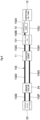
Fig. 5 is a configuration view showing a supply path and a return path of operating oil to a hydraulic motor for travel schematically. -
Fig. 6 is a configuration view showing a supply path and a return path of operating oil to a hydraulic motor for travel schematically according to a comparative example. - Hereinafter, a hydraulic excavator that is taken as a representative example of a construction machine according to an embodiment of the present invention will in detail be explained referring to
Fig. 1 to Fig. 6 . - In
Fig. 1 , a hydraulic excavator 1 as a representative example of a construction machine is an ultra large hydraulic excavator (mining hydraulic excavator) used for excavation in a mine (open-pit mining) or the like. The hydraulic excavator 1 is provided with an after-mentionedlower traveling structure 15, an upper revolvingstructure 3 mounted via a revolvingdevice 2 on thelower traveling structure 15 to be capable of revolving thereto, and aworking mechanism 4 that is rotatably provided on the front side of the upper revolvingstructure 3 to perform an excavating work of earth and sand, or the like. - The revolving
device 2 is a mechanism for revolving the upper revolvingstructure 3 on thelower traveling structure 15. The revolvingdevice 2 is provided with a revolvingwheel 2A composed of a ring-shaped bearing provided between atruck frame 16 of thelower traveling structure 15 and a revolvingframe 5 of the upper revolvingstructure 3, and a revolving motor (not shown) that engages with an inner ring of the revolvingwheel 2A to revolve the upper revolvingstructure 3. - The upper revolving
structure 3 is provided with the revolvingframe 5 formed as a support structure on the front side of which theworking mechanism 4 is provided, acab 6 that is mounted on the left front side of the revolvingframe 5 to form an operator's room inside, a counterweight 7 that is attached to the rear part of the revolvingframe 5 to act as a weight balance to theworking mechanism 4, and ahousing 8 that is positioned between thecab 6 and the counterweight 7 to accommodate an after-mentionedengine 9 mounted on the revolvingframe 5, and the like therein. An operator's seat on which an operator sits and control devices that are positioned respectively on the front side, on the left side and on the right side of the operator's seat to control the hydraulic excavator 1 (any one of them is not shown) are provided inside thecab 6. - The
engine 9 as a prime mover is provided on the revolvingframe 5 to be positioned in front of the counterweight 7. Theengine 9 is configured as a diesel engine, for example. Theengine 9 is singularly provided in a horizontal state to extend in a left-right direction on the rear side of the revolvingframe 5. For example, after-mentionedhydraulic pumps 10 are attached on the right side to theengine 9. In addition, a heat exchange device composed of a radiator, an oil cooler, a capacitor and the like (any one of them is not shown) is arranged on the left side to theengine 9. - It should be noted that a hybrid prime mover composed of a combination of a diesel engine and an electric motor or an electric motor unit may be used as the prime mover. On the other hand, the prime mover may be provided in a longitudinal state to extend in a front-back direction of the upper revolving
structure 3. In addition, two prime movers may be mounted to line up in the left-right direction. - The
hydraulic pumps 10 are attached to the right side to theengine 9. Thehydraulic pumps 10 include a main pump that delivers operating oil (pressurized oil) for operating a hydraulic actuator of theworking mechanism 4, a revolving motor of the revolvingdevice 2, ahydraulic motor 20 for travel of thelower traveling structure 15 and the like, and a pilot pump that delivers operating oil (pressurized oil) for operating control valves (including acontrol valve 23 for travel motor) that control these hydraulic actuators. The plurality ofhydraulic pumps 10 are configured of a swash plate hydraulic pump of variable displacement type, a bent axis hydraulic pump, an axial piston type hydraulic pump, or the like. - A
center joint 11 is provided between thelower traveling structure 15 and the upper revolvingstructure 3 to be positioned in a center of the revolvingwheel 2A (acylindrical part 17A of an after-mentioned center frame 17) of the revolvingdevice 2 serving as a revolving center. Thecenter joint 11, even in a case where the upper revolvingstructure 3 revolves relative to thelower traveling structure 15, can make circulation of operating oil for operating the hydraulic actuators, pilot operating oil for operating thecontrol valve 23 for travel motor and the like, and electricity (signals) between thelower traveling structure 15 and theupper revolving structure 3. - The
center joint 11 includes a body to be attached to the revolvingframe 5 of the upper revolvingstructure 3 and a spindle that is rotatably provided inside the body in a state of projecting to the lower side from the body and is attached to thetruck frame 16 of thelower traveling structure 15. In addition, thecenter joint 11 is provided with a plurality of circular oil paths extending in a circumferential direction between the body and the spindle and a plurality of oil paths that open to an outer surface of the body and an outer surface of the spindle in a state of being communicated individually with the plurality of circular oil paths (any one of them is not shown). - In addition, a high-
pressure pipe part 25B on the pump side to be described later, a low-pressure pipe part 25G on the tank side, a harness on the pump side (any one of them is not shown) and the like are connected to the body. On the other hand, a high-pressure pipe part 25C on the valve side, a low-pressure pipe part 25F on the valve side, a pilot pipe part on the valve side, a harness on the valve side (any one of them is not shown) and the like are connected to the spindle. - As schematically shown in
Fig. 5 , anoperating oil tank 12 serves to store the operating oil for supply to thehydraulic pump 10 and is provided on the revolvingframe 5. Theoperating oil tank 12 is connected via an after-mentioned supply low-pressure pipe part 25A to thehydraulic pump 10. In addition, the low-pressure pipe part 25G on the tank side is connected to theoperating oil tank 12. - A
control valve device 13 is provided on the revolvingframe 5 to be positioned in front of theengine 9. Thecontrol valve device 13 includes, for example, a manifold composed of a block-shaped structure and a plurality of control valves attached to the manifold. The control valve device 13 (control valve) controls the flow of operating oil that is delivered to the hydraulic actuator of theworking mechanism 4 and the revolving motor of the revolvingdevice 2 from thehydraulic pump 10. - Here, the
control valve device 13, as the after-mentionedcontrol valves 23 for travel motor are relocated to the lower traveling structure 15-side, can be downsized by a size of thecontrol valves 23 for travel motor. In addition, for installing thecontrol valves 23 for travel motor, spaces for performing the maintenance to pipes of thecontrol valves 23 for travel motor, connection parts of hoses, and between surrounding valves and structures are required. On the other hand, relocating thecontrol valves 23 for travel motor enables these spaces to be omitted, thereby downsizing thecontrol valve device 13 furthermore. - A
control valve device 14 for pilot is provided on the revolvingframe 5 to be positioned, for example, in back of thecontrol valve device 13. Thecontrol valve device 14 for pilot includes, as similar to thecontrol valve device 13, a manifold and a plurality of control valves. Thecontrol valve device 14 for pilot controls the flow of operating oil for pilot to be supplied to the control valves of thecontrol valve device 13 and the after-mentionedcontrol valves 23 for travel motor. It should be noted that thecontrol valve device 14 for pilot may be installed to thelower traveling structure 15. - The
lower traveling structure 15 travels due to rotation of drivingwheels 19 caused by the after-mentionedhydraulic motors 20 for travel. Thelower traveling structure 15 is provided with the after-mentionedtruck frame 16, the drivingwheels 19, thehydraulic motors 20 for travel,idler wheels 21, crawler tracks 22, thecontrol valves 23 for travel motor,brake valves 24, and ahydraulic pipe 25. - The
truck frame 16 is provided with thecenter frame 17 positioned in the center and the side frames 18 provided on thecenter frame 17 in both of the left and right sides (refer toFig. 1 andFig. 4 ). Thecenter frame 17 is provided with thecylindrical part 17A that is positioned in the center to project upwards, and the revolvingwheel 2A in the revolvingdevice 2 is attached on thecylindrical part 17A. The center joint 11 is located on thecenter frame 17 in the center position of thecylindrical part 17A. In addition, as shown inFig. 2 , thecenter frame 17 is provided withfront leg parts 17B that are positioned in the front side (idler wheel 21-side) to extend to both of the left and right sides andrear leg parts 17C that are positioned in the rear side (driving wheel 19-side) to extend to both of the left and right sides. - Further, as shown in
Fig. 3 , thecenter frame 17 is configured so that rear surfaces of the left and rightrear leg parts 17C are formed asvalve attaching surfaces 17D. Thevalve attaching surface 17D is arranged to face thehydraulic motors 20 for travel in the front-back direction on the surface on which thecontrol valves 23 for travel motor and thebrake valves 24 to be described later are attached. - The side frames 18 are provided on both of the left and right sides of the
center frame 17, specifically tip end parts of thefront leg part 17B and therear leg part 17C on the left side and tip leg parts of thefront leg part 17B and therear leg part 17C on the right side to extend in the front-back direction. - As shown in
Fig. 1 andFig. 4 , thedriving wheel 19 is provided on the rear part of theside frame 18. Thedriving wheel 19 includes a reduction gear, a drive tumbler (or a sprocket), and the like, wherein the reduction gear is attached to the rear part of theside frame 18. The after-mentionedhydraulic motors 20 for travel are attached to thedriving wheel 19. - As shown in
Fig. 4 , thehydraulic motors 20 for travel are attached to the inner side of thedriving wheel 19 in the left-right direction, and for example, two hydraulic motors line up in the front-back direction. Because of this configuration, the twohydraulic motors 20 for travel attached to theleft driving wheel 19 and the twohydraulic motors 20 for travel attached to theright driving wheel 19 project to the inner side from thedriving wheel 19 to face to each other (refer toFig. 2 andFig. 3 ). Thehydraulic motor 20 for travel includes, for example, a variable capacity type swash plate hydraulic motor, a bent axis hydraulic motor, a radial piston hydraulic motor, or the like. Thehydraulic motors 20 for travel rotate a rotational shaft (not shown) by supply of operating oil (pressurized oil) via switching high-pressure pipe parts control valves 23 for travel motor and rotate thedriving wheel 19 via the reduction gear by its rotating force. It should be noted that thehydraulic motor 20 for travel may comprise one or more hydraulic motors according to output as needed. - The
idler wheel 21 is rotatably provided in the front part of theside frame 18 at the opposite side to thedriving wheel 19 in the front-back direction (only the right side inFig. 1 is shown). In addition, thecrawler track 22 is wound around between thedriving wheel 19 and theidler wheel 21 to be capable of going around it. - Here, in the
lower traveling structure 15 thedriving wheel 19 is located on the rear side so that the ground side of thecrawler track 22 is tensed in the forward travel to be used heavily. The front-back direction of thelower traveling structure 15 is determined based upon this configuration. It should be noted that the front-back direction of thelower traveling structure 15 corresponds to the forward direction and the rearward direction of thelower traveling structure 15. On the other hand, in a state where the upper revolvingstructure 3 is revolved by 180 degrees on thelower traveling structure 15, the front-back direction becomes the opposite as viewed from the upper revolvingstructure 3. - The
control valves 23 for travel motor are attached to thelower traveling structure 15. Thecontrol valves 23 for travel motor correspond to the twohydraulic motors 20 for travel provided in theleft driving wheel 19 to comprise two control valves for travel motor attached to the leftvalve attaching surface 17D and correspond to the twohydraulic motors 20 for travel provided in theright driving wheel 19 to comprise two control valves for travel motor attached to the rightvalve attaching surface 17D. Thecontrol valve 23 for travel motor is composed of a pilot type switching valve that controls the flow of operating oil to be delivered to thehydraulic motor 20 for travel from thehydraulic pump 10. That is, thecontrol valve 23 for travel motor can switch the rotating direction (forward direction and reverse direction) of thehydraulic motor 20 for travel. - Here, as shown in
Fig. 3 , the twocontrol valves 23 for travel motor are provided to shift to each other in the left-right direction and in the upper-lower direction. Specifically thecontrol valve 23 for travel motor positioned on the inner side in the left-right direction is located in a position higher than thecontrol valve 23 for travel motor positioned on the outer side in the left-right direction. Because of this configuration, even in a case where the twocontrol valves 23 for travel motor are arranged to line up, the working space can be secured by changing the height position to facilitate the maintenance of inspection, repair, replacement and the like. In addition, since the fourcontrol valves 23 for travel motor in total are arranged in thelower traveling structure 15, thecontrol valve device 13 can be downsized by a size of the fourcontrol valves 23 for travel motor. - In addition, by utilizing the rear surface of the
center frame 17 to install thecontrol valves 23 for travel motor, thecontrol valves 23 for travel motor can be arranged in the intermediate position between the center joint 11 and thehydraulic motors 20 for travel. According to this configuration, thehydraulic pipe 25 can be shortened and orderly be arranged, therefore improving the workability on the assembling work, the maintenance and the like. In addition, it is possible to facilitate the maintenance of thecontrol valves 23 for travel motor arranged on the rear surface of thecenter frame 17. - The
brake valves 24 are attached via thecontrol valves 23 for travel motor to thelower traveling structure 15. Thebrake valves 24 correspond to, as similar to thecontrol valves 23 for travel motor, the twohydraulic motors 20 for travel provided in theleft driving wheel 19 to comprise twobrake valves 24 attached to overlap with the left thecontrol valves 23 for travel motor. In addition, thebrake valves 24 correspond to the twohydraulic motors 20 for travel provided in theright driving wheel 19 to comprise twobrake valves 24 attached to overlap with the right thecontrol valves 23 for travel motor. Thebrake valve 24 limits the flow of operating oil to apply a brake to thehydraulic motors 20 for travel. - Further, as to the
brake valves 24, as similar to thecontrol valves 23 for travel motor, thebrake valve 24 positioned on the inner side is located to shift to a position higher than thebrake valve 24 positioned on the outer side. Because of this configuration, even in a case where the twobrake valves 24 are arranged to line up, the working space can be secured to facilitate the maintenance of inspection, repair, replacement and the like. In addition, since thebrake valve 24 is attached to overlap with thecontrol valve 23 for travel motor, an attaching space is not required on thevalve attaching surface 17D, and furthermore, the pipe for connection of thecontrol valve 23 for travel motor and thebrake valve 24 can be omitted. - As schematically shown in
Fig. 5 , thehydraulic pipe 25 establishes connection between the operatingoil tank 12 and thehydraulic motor 20 for travel via thehydraulic pump 10, the center joint 11, thecontrol valve 23 for travel motor and thebrake valve 24. In addition, thehydraulic pipe 25 is provided with a high-pressure pipe part (thick line inFig. 5 ) in which high-pressure operating oil delivered from thehydraulic pump 10 flows and a low-pressure pipe part (thin line inFig. 5 ) in which low-pressure operating oil returned back to the operatingoil tank 12 from thecontrol valve 23 for travel motor flows. Four sets of thehydraulic pipes 25 in total are provided to correspond to the fourhydraulic motors 20 for travel (one set composed of pipes by the supply side and by the return side x four). - The configuration of the
hydraulic pipe 25 will specifically be explained along a flow direction of operating oil. Thehydraulic pipe 25 is configured of the supply low-pressure pipe part (supply pipe part) 25A for connection between the operatingoil tank 12 and thehydraulic pump 10, the pump-side high-pressure pipe part (supply pipe part) 25B for connection between thehydraulic pump 10 and the center joint 11, the valve-side high-pressure pipe part (supply pipe part) 25C for connection between the center joint 11 and thecontrol valve 23 for travel, the two switching high-pressure pipe parts (high-pressure pipe parts) 25D, 25E for connection between thebrake valve 24 and thehydraulic motor 20 for travel, the valve-side low-pressure pipe part (low-pressure pipe part) 25F for connection between thecontrol valve 23 for travel motor and the center joint 11, and the tank-side low-pressure pipe part (low-pressure pipe part) 25G for connection between the center joint 11 and the operatingoil tank 12. The high-pressure operating oil flows into one, which acts as the supply side, of the two switching high-pressure pipe parts - The high-pressure pipe parts composed of the pump-side high-
pressure pipe part 25B, the valve-side high-pressure pipe part 25C and the two switching high-pressure pipe parts hydraulic pump 10. The pipe to be used in the high-pressure pipe part includes a metallic pipe and a hose. In a case where the high-pressure pipe part is composed of a metallic pipe, a thick metallic pipe, a metallic pipe high in strength of a material or the like is used. In addition, in a case where the high-pressure pipe part is composed of a hose, there is used a thick pressure-resistant hose composed of a plurality of layers composed of radially overlayed materials with strength. Therefore, the high-pressure pipe part, as compared to the low-pressure pipe part, requires a larger arrangement space, is more expensive and is more difficult in processing and maneuverability. - The low-pressure pipe parts composed of the supply low-
pressure pipe part 25A, the valve-side low-pressure pipe part 25F and the tank-side low-pressure pipe part 25G only require durability to the extent of being capable of withstanding the pressure when the operating oil returned back to the operatingoil tank 12 in an atmospheric air state flows therein. The pipe to be used in the low-pressure pipe part includes, as similar to the high-pressure pipe part, a metallic pipe and a hose. In a case where the low-pressure pipe part is composed of a metallic pipe, a metallic pipe that is thin and is low in strength or the like is used. In addition, in a case where the low-pressure pipe part is composed of a hose, there may be used a hose low in strength. Therefore, the low-pressure pipe part, as compared to the high-pressure pipe part, can make the arrangement space smaller by using a narrow pipe and hose and besides, is higher in a freedom degree of bending at the arrangement, is less expensive and is easier in processing and maneuverability. - The valve-side high-
pressure pipe part 25C and the valve-side low-pressure pipe part 25F, which are arranged in thecenter frame 17, of thehydraulic pipe 25 extend upwards along thevalve attaching surface 17D from thecontrol valve 23 for travel motor, thereafter bend in a position of an upper surface of therear leg part 17C to extend to the front side, bend to thecylindrical part 17A-side in the lateral portion position of thecylindrical part 17A, and is connected through the lateral portion of thecylindrical part 17A to the center joint 11. - Here, as shown in
Fig. 2 , the valve-side low-pressure pipe part 25F, which is between the center joint 11 and thecontrol valve 23 for travel motor, of the low-pressure pipe part is arranged through a position more separate from thecrawler track 22 of thelower traveling structure 15 than the valve-side high-pressure pipe part 25C extending in parallel therewith. In other words, the valve-side low-pressure pipe part 25F is arranged through a position closer to thecylindrical part 17A (revolvingwheel 2A of the revolving device 2) of thecenter frame 17 than the valve-side high-pressure pipe part 25C. - Because of this configuration, even when stones or the concrete pieces bounce on the
crawl track 22 to fly to the center frame 17-side, since the valve-side high-pressure pipe part 25C having high strength is located in a position close to thecrawler track 22, the valve-side low-pressure pipe part 25F can be protected from stones, the concrete pieces and the like. -
Fig. 6 shows a comparative example in which acontrol valve 101 for travel motor is provided in the upper revolvingstructure 3. Therefore, ahydraulic pipe 102 in the comparative example is configured of a supply low-pressure pipe part 102A for connection between the operatingoil tank 12 and thehydraulic pump 10, a first pump-side high-pressure pipe part 102B for connection between thehydraulic pump 10 and thecontrol valve 101 for travel motor, a second pump-side high-pressure pipe part 102C for connection between thecontrol valve 101 for travel motor and the center joint 11, a valve-side high-pressure pipe part 102D for connection between the center joint 11 and thebrake valve 24, motor-side high-pressure pipe parts brake valve 24 and thehydraulic motor 20 for travel, a valve-side high-pressure pipe part 102G for connection between thebrake valve 24 and the center joint 11, a tank-side high-pressure pipe part 102H for connection between the center joint 11 and thecontrol valve 101 for travel motor, and a tank-side low-pressure pipe part 102J for connection between thecontrol valve 101 for travel motor and the operatingoil tank 12. - In this case, a path in which high-pressure operating oil flows is switched following the switching of the forward rotation and the reverse rotation of the
hydraulic motor 20 for travel between thecontrol valve 101 for travel motor and thehydraulic motor 20 for travel. Therefore, all pipe parts of a pipe between thecontrol valve 101 for travel motor and thehydraulic motor 20 for travel are composed of high-pressure pipe parts. That is, the low-pressure pipe parts in the comparative example inFig. 6 are composed of the supply low-pressure pipe part 102A and the tank-side low-pressure pipe part 102J only. - On the other hand, in the present embodiment shown in
Fig. 5 , many sections of the hydraulic pipe can be composed of the low-pressure pipe parts as compared to the comparative example inFig. 6 (that is, in a case where thecontrol valve 101 for travel motor is provided in the upper revolving structure 3). Specifically in thehydraulic pipe 25 the supply low-pressure pipe part 25A, the valve-side low-pressure pipe part 25F and the tank-side low-pressure pipe part 25G can be made to the low-pressure pipe parts. That is, according to the present embodiment a ratio of the low-pressure pipe parts with easiness and a high freedom degree of the arrangement relative to the entire pipe length of thehydraulic pipe 25 can be increased by considerable amount. Therefore, according to the present embodiment a freedom degree and easiness of the arrangement of thehydraulic pipe 25 largely improve as a whole. - For example, in the present embodiment the tank-side low-
pressure pipe part 25G, that is, the pipe for connection of the center joint 11 and the operatingoil tank 12 can be arranged directly (without via thecontrol valve 23 for travel motor) within the upper revolvingstructure 3. Therefore, for example, the tank-side low-pressure pipe part 25G can be made shorter than the pipe length of the tank-side high-pressure pipe part 102H and the tank-side low-pressure pipe part 102J in the comparative. - The hydraulic excavator 1 according to the present embodiment has the configuration as described above, and hereinafter, an explanation will be made of the operation of the hydraulic excavator 1.
- An operator who has boarded on the
cab 6 starts up theengine 9 to drive thehydraulic pump 10. In this state, the operator operates the control device for travel, thus making it possible to move thelower traveling structure 15 forward or backward. In addition, the operator operates the control device for working, thus making it possible to rotate the workingmechanism 4 to perform an excavating operation of earth and sand or the like. - Here, the flow of the operating oil at the time of causing the
lower traveling structure 15 to travel will be described. When thehydraulic pump 10 is driven by theengine 9 and the operating oil is supplied to thehydraulic pump 10 through the supply low-pressure pipe part 25A from the operatingoil tank 12, the high-pressure operating oil is delivered from thehydraulic pump 10. In addition, the operating oil is supplied through the supply pipe parts composed of the pump-side high-pressure pipe part 25B and the valve-side high-pressure pipe part 25C to thecontrol valve 23 for travel motor. Thecontrol valve 23 for travel motor is switched based upon a control signal to be supplied through a pilot pipe part, and for example, the operating oil is supplied to thehydraulic motor 20 for travel from the switching high-pressure pipe part 25D (high-pressure pipe part) . On the other hand, the operating oil that has driven thehydraulic motor 20 for travel is returned back through the switching high-pressure pipe part 25E to thecontrol valve 23 for travel motor, and further, is returned back through the low-pressure pipe parts composed of the valve-side low-pressure pipe part 25F and the tank-side low-pressure pipe part 25G to the operatingoil tank 12. - Thus, in the present embodiment the hydraulic excavator 1 includes: the automotive
lower traveling structure 15 by thehydraulic motor 20 for travel; and the upper revolvingstructure 3 mounted via the revolvingdevice 2 on thelower traveling structure 15 to be capable of revolving thereto. On top of that, there is provided thecontrol valve 23 for travel motor to control the flow of the operating oil that is delivered from thehydraulic pump 10 to thehydraulic motor 20 for travel, and thecontrol valve 23 for travel motor is attached to thelower traveling structure 15. - As a result, since the
control valve device 13 mounted on the upper revolvingstructure 3 can be downsized by a size of thecontrol valves 23 for travel motor, the installation space can be secured in the upper revolvingstructure 3 by a size to the extent that thecontrol valve device 13 is downsized. In addition, the space for inspection, repair, replacement and the like of the equipment devices composed of theengine 9, thehydraulic pump 10, thecontrol valve device 13 and the like mounted on the upper revolvingstructure 3 can be secured thereon. As a result, the space for installing the equipment devices necessary for the energy saving of the hydraulic excavator 1 can be secured and the workability at the time of performing the maintenance of the equipment devices including the equipment devices for energy saving can improve. - Also, in the present embodiment the
hydraulic pipe 25 establishes the connection between the operatingoil tank 12 and thehydraulic motor 20 for travel. The hydraulic pipe 25 is configured of the supply low-pressure pipe part 25A, the pump-side high-pressure pipe part 25B and the valve-side high-pressure pipe part 25C as the supply pipe parts that establish the connection between the operating oil tank 12, the hydraulic pump 10 and the control valve 23 for travel motor to supply the operating oil thereto, the two switching high-pressure pipe parts 25D, 25E as the high-pressure pipe parts that are provided on the lower traveling structure 15 to establish the connection between the control valve 23 for travel motor and the hydraulic motor 20 for travel, wherein the high-pressure operating oil that is delivered from the hydraulic pump 10 and is supplied to the hydraulic motor 20 for travel flows in the high-pressure pipe parts, and the valve-side low-pressure pipe part 25F and the tank-side low-pressure pipe part 25G as the low-pressure pipe parts that are provided across from the lower traveling structure 15 to the upper revolving structure 3 to establish the connection between the control valve 23 for travel motor and the operating oil tank 12, wherein the low-pressure operating oil that is discharged from the hydraulic motor 20 for travel and is returned back to the operating oil tank 12 from the control valve 23 for travel motor flows in the low-pressure pipe parts. - Therefore, in the present embodiment a ratio of the low-pressure pipe parts relative to the entire length of the
hydraulic pipe 25 is high (a ratio of the high-pressure pipe parts is small), and the freedom degree and the easiness of the arrangement of thehydraulic pipe 25 and the easiness of the removal thereof improve as a whole. Besides, the improvement effect of the maintenance and the reduction effect of costs on thehydraulic pipe 25 can be obtained. - The
lower traveling structure 15 is provided with thetruck frame 16 having thecenter frame 17 and the side frames 18 extending in the front-back direction on both of the left and right sides of thecenter frame 17, the drivingwheels 19 that are provided on the rear parts of the side frames 18 and rotated by thehydraulic motors 20 for travel, theidler wheels 21 provided on the front parts of the side frames 18, and the crawler tracks 22 each of which is wound around between thedriving wheel 19 and theidler wheel 21. Thecenter frame 17 is provided with thevalve attaching surface 17D on the rear surface facing thehydraulic motor 20 for travel in the front-back direction. On top of that, thecontrol valve 23 for travel motor is attached on thevalve attaching surface 17D of thecenter frame 17. - Therefore, the
control valve 23 for travel motor is installed by utilizing the rear surface of thecenter frame 17, thereby making it possible to be located in the intermediate position between the center joint 11 and thehydraulic motor 20 for travel. Because of this configuration, thehydraulic pipe 25 can be arranged shortly and orderly to improve the workability of the assembly work, the maintenance and the like. In addition, thecontrol valve 23 for travel motor provided on the rear surface of thecenter frame 17 is easy to reach, thereby making it possible to be easily subject to maintenance. - The center joint 11 is provided in the revolving center position of the revolving
device 2 to cause the operating oil to flow between thelower traveling structure 15 and the upper revolvingstructure 3. Thebrake valve 24 for giving a brake to thehydraulic motor 20 for travel is provided in thelower traveling structure 15. Thehydraulic pipe 25 is provided for connection of the operatingoil tank 12 and thehydraulic motor 20 for travel via thehydraulic pump 10, the center joint 11, thecontrol valve 23 for travel motor and thebrake valve 24. In addition, the valve-side low-pressure pipe part 25F and the tank-side low-pressure pipe part 25G as the low-pressure pipe parts are provided via the center joint 11 across the upper revolvingstructure 3 and thelower traveling structure 15. On top of this, the valve-side low-pressure pipe part 25F of the low-pressure pipe part between the center joint 11 and thecontrol valve 23 for travel motor is arranged through a position more separate from thecrawler track 22 than the valve-side high-pressure pipe part 25C as the high-pressure pipe part. - Because of this configuration, even when stones or concrete pieces are bounced by the
crawler track 22 to fly to the center frame 17-side, the valve-side high-pressure pipe part 25C composed of a pipe with high strength is located in a position close to thecrawler track 22. As a result, since the valve-side low-pressure pipe part 25F is far from a place where stones or concrete pieces are caused to fly and the valve-side high-pressure pipe part 25C acts as a wall against the flying stones or concrete pieces, the valve-side low-pressure pipe part 25F can be protected from stones, concrete pieces or the like. - The
control valve 23 for travel motor comprises a plurality of control valves that are provided in positions lining up in the left-right direction and in positions shifting in the upper-lower direction, and, for example, two control valves are provided in the left and right positions respectively. Therefore, even when twocontrol valves 23 for travel motor are located to line up in positions close from each other, the working space for hanging up tools and the like can be secured by changing the height position, thus facilitating the maintenance of inspection, repair, replacement and the like. - It should be noted that there is shown as an example a case where the embodiment is configured so that the valve-side high-
pressure pipe part 25C and the valve-side low-pressure pipe part 25F of thehydraulic pipe 25 pass through the lateral portion (side frame 18-side) of thecylindrical part 17A in thecenter frame 17. However, the present invention is not limited to this configuration but, for example, may be configured so that a valve-side high-pressure pipe part and a valve-side low-pressure pipe part of a hydraulic pipe pass through a rear portion of a cylindrical part in a center frame. - There is shown as an example a case where the embodiment is configured so that the
control valve 23 for travel motor is attached to thevalve attaching surface 17D of thecenter frame 17 and thebrake valve 24 is attached to overlap with thecontrol valve 23 for travel motor. However, the present invention is not limited to this configuration but, for example, may be configured so that a brake valve is attached directly to a valve attaching surface of a center frame. In this case, the connection between a control valve for travel motor and a brake valve is established by a high-pressure pipe part. - It should be noted that the embodiment is explained by taking as an example a case of the hydraulic excavator 1 provided with the working
mechanism 4 of a backhoe type as the construction machine. However, the present invention is not limited thereto, but may be applied widely also to other construction machines including a hydraulic excavator provided with a working mechanism of a loading excavator type. -
- 1: HYDRAULIC EXCAVATOR (CONSTRUCTION MACHINE)
- 2: REVOLVING DEVICE
- 3: UPPER REVOLVING STRUCTURE
- 9: ENGINE (PRIME MOVER)
- 10: HYDRAULIC PUMP
- 11: CENTER JOINT
- 12: OPERATING OIL TANK
- 15: LOWER TRAVELING STRUCTURE
- 16: TRUCK FRAME
- 17: CENTER FRAME
- 17D: VALVE ATTACHING SURFACE
- 18: SIDE FRAME
- 19: DRIVING WHEEL
- 20: HYDRAULIC MOTOR FOR TRAVEL
- 21: IDLER WHEEL
- 22: CRAWLER TRACK
- 23: CONTROL VALVE FOR TRAVEL MOTOR
- 24: BRAKE VALVE
- 25: HYDRAULIC PIPE
- 25A: SUPPLY LOW-PRESSURE PIPE PART (SUPPLY PIPE PART)
- 25B: PUMP-SIDE HIGH-PRESSURE PIPE PART (SUPPLY PIPE PART)
- 25C: VALVE-SIDE HIGH-PRESSURE PIPE PART (SUPPLY PIPE PART)
- 25D: SWITCHING HIGH-PRESSURE PIPE PART (HIGH-PRESSURE PIPE PART)
- 25E: SWITCHING HIGH-PRESSURE PIPE PART (HIGH-PRESSURE PIPE PART)
- 25F: VALVE-SIDE LOW-PRESSURE PIPE PART (LOW-PRESSURE PIPE PART)
- 25G: TANK-SIDE LOW-PRESSURE PIPE PART (LOW-PRESSURE PIPE PART)
Claims (4)
- A construction machine comprising:an automotive lower traveling structure by a hydraulic motor for travel; andan upper revolving structure mounted via a revolving device on the lower traveling structure to be capable of revolving thereto,the upper revolving structure including:a prime mover;an operating oil tank; anda hydraulic pump that is driven by the prime mover to deliver operating oil stored in the operating oil tank, characterized by including:a control valve for travel motor provided in the lower traveling structure to control the flow of the operating oil that is delivered from the hydraulic pump to the hydraulic motor for travel; anda hydraulic pipe that establishes connection between the operating oil tank and the hydraulic motor for travel, wherein the hydraulic pipe includes:a supply pipe part that establishes connection between the operating oil tank, the hydraulic pump and the control valve for travel motor for supply of the operating oil;a high-pressure pipe part that is provided in the lower traveling structure to establish connection between the control valve for travel motor and the hydraulic motor for travel and in which high-pressure operating oil that is delivered from the hydraulic pump and is supplied to the hydraulic motor for travel flows; anda low-pressure pipe part that is provided across from the lower traveling structure to the upper revolving structure to establish connection between the control valve for travel motor and the operating oil tank and in which low-pressure operating oil that is discharged from the hydraulic motor for travel and is returned back from the control valve for travel motor to the operating oil tank flows.
- The construction machine according to claim 1, wherein the lower traveling structure includes:a truck frame including a center frame and side frames extending in the front-back direction on both of the left and right sides of the center frame;a driving wheel that is provided on the rear part of the side frame and is rotated by the hydraulic motor for travel;an idler wheel that is provided on the front part of the side frame; anda crawler track that is wound around between the driving wheel and the idler wheel, whereinthe center frame is provided with a valve attaching surface on the rear surface facing the hydraulic motor for travel in the front-back direction, andthe control valve for travel motor is attached on the valve attaching surface of the center frame.
- The construction machine according to claim 2,
further comprising:a center joint provided in a revolving center position of the revolving device to cause the operating oil to flow between the lower traveling structure and the upper revolving structure whereinthe low-pressure pipe part is provided via the center joint across between the upper revolving structure and the lower traveling structure, andthe low-pressure pipe part is provided with a valve-side low-pressure pipe part between the center joint and the control valve for travel motor, the valve-side low-pressure pipe part being arranged through a position more separate from the crawler track than the high-pressure pipe part. - The construction machine according to claim 1,
wherein
the control valve for travel motor comprises a plurality of control valves that are provided in positions lining up in the left-right direction and in positions shifting to each other in the upper-lower direction.
Applications Claiming Priority (2)
| Application Number | Priority Date | Filing Date | Title |
|---|---|---|---|
| JP2022066149 | 2022-04-13 | ||
| PCT/JP2023/013560 WO2023199761A1 (en) | 2022-04-13 | 2023-03-31 | Construction machine |
Publications (2)
| Publication Number | Publication Date |
|---|---|
| EP4484651A1 true EP4484651A1 (en) | 2025-01-01 |
| EP4484651A4 EP4484651A4 (en) | 2026-03-04 |
Family
ID=88329531
Family Applications (1)
| Application Number | Title | Priority Date | Filing Date |
|---|---|---|---|
| EP23788181.8A Pending EP4484651A4 (en) | 2022-04-13 | 2023-03-31 | CONSTRUCTION MACHINE |
Country Status (5)
| Country | Link |
|---|---|
| US (1) | US20250207363A1 (en) |
| EP (1) | EP4484651A4 (en) |
| JP (1) | JP7661618B2 (en) |
| CN (1) | CN118922605A (en) |
| WO (1) | WO2023199761A1 (en) |
Family Cites Families (6)
| Publication number | Priority date | Publication date | Assignee | Title |
|---|---|---|---|---|
| JPH01150653A (en) | 1987-12-04 | 1989-06-13 | Ricoh Co Ltd | Paper feeding method in printer |
| JP3999090B2 (en) * | 2002-09-24 | 2007-10-31 | 新キャタピラー三菱株式会社 | Hose support structure in construction machinery |
| JP2006070481A (en) * | 2004-08-31 | 2006-03-16 | Yanmar Co Ltd | Tractor |
| US9745940B2 (en) * | 2014-02-28 | 2017-08-29 | Caterpillar Inc. | Machine having hydraulic start assist system |
| JP6420071B2 (en) * | 2014-06-24 | 2018-11-07 | 古河ロックドリル株式会社 | Attachment operation monitoring device and attachment operation monitoring program |
| JP7581124B2 (en) * | 2021-05-24 | 2024-11-12 | ヤンマーホールディングス株式会社 | Construction Machinery |
-
2023
- 2023-03-31 WO PCT/JP2023/013560 patent/WO2023199761A1/en not_active Ceased
- 2023-03-31 US US18/849,015 patent/US20250207363A1/en active Pending
- 2023-03-31 EP EP23788181.8A patent/EP4484651A4/en active Pending
- 2023-03-31 JP JP2024514887A patent/JP7661618B2/en active Active
- 2023-03-31 CN CN202380028855.2A patent/CN118922605A/en active Pending
Also Published As
| Publication number | Publication date |
|---|---|
| JPWO2023199761A1 (en) | 2023-10-19 |
| US20250207363A1 (en) | 2025-06-26 |
| EP4484651A4 (en) | 2026-03-04 |
| WO2023199761A1 (en) | 2023-10-19 |
| CN118922605A (en) | 2024-11-08 |
| JP7661618B2 (en) | 2025-04-14 |
Similar Documents
| Publication | Publication Date | Title |
|---|---|---|
| US6990757B2 (en) | Wheeled work vehicle | |
| US9016418B2 (en) | Construction machine | |
| CN110709562B (en) | work machinery | |
| JP5468393B2 (en) | Construction machinery | |
| US4467604A (en) | Hydrostatic drive system for an excavator | |
| CN119698505A (en) | Construction Machinery | |
| US20250207363A1 (en) | Construction machine | |
| JP3178392B2 (en) | Revolving superstructure of construction equipment | |
| EP3530816A1 (en) | Hydraulic shovel | |
| US20250129572A1 (en) | Construction machine | |
| JP7762491B2 (en) | Construction machinery | |
| EP4424923A1 (en) | Construction machine | |
| US7921641B2 (en) | Arrangement and method for delivering hydraulic fluid in a work vehicle | |
| JP4145698B2 (en) | Construction machinery and swivel device | |
| CN112523283A (en) | Construction machine | |
| JP7654588B2 (en) | Swash plate type rotating machine | |
| JP7848102B2 (en) | Work vehicles | |
| JP2001191807A (en) | Vehicle | |
| JP2002013157A (en) | Construction equipment valve device arrangement structure | |
| JPH10219742A (en) | Turning type vehicle | |
| JP3412577B2 (en) | Hydraulic excavator | |
| JP2026036974A (en) | Work vehicles | |
| JP2012167482A (en) | Arrangement structure of control valve and shuttle block of construction machine | |
| JP2012237172A (en) | Construction machine | |
| JPH09177129A (en) | Valve support equipment for construction machinery |
Legal Events
| Date | Code | Title | Description |
|---|---|---|---|
| STAA | Information on the status of an ep patent application or granted ep patent |
Free format text: STATUS: THE INTERNATIONAL PUBLICATION HAS BEEN MADE |
|
| PUAI | Public reference made under article 153(3) epc to a published international application that has entered the european phase |
Free format text: ORIGINAL CODE: 0009012 |
|
| STAA | Information on the status of an ep patent application or granted ep patent |
Free format text: STATUS: REQUEST FOR EXAMINATION WAS MADE |
|
| 17P | Request for examination filed |
Effective date: 20240923 |
|
| AK | Designated contracting states |
Kind code of ref document: A1 Designated state(s): AL AT BE BG CH CY CZ DE DK EE ES FI FR GB GR HR HU IE IS IT LI LT LU LV MC ME MK MT NL NO PL PT RO RS SE SI SK SM TR |
|
| DAV | Request for validation of the european patent (deleted) | ||
| DAX | Request for extension of the european patent (deleted) | ||
| A4 | Supplementary search report drawn up and despatched |
Effective date: 20260202 |
|
| RIC1 | Information provided on ipc code assigned before grant |
Ipc: E02F 9/00 20060101AFI20260127BHEP Ipc: E02F 9/02 20060101ALI20260127BHEP Ipc: E02F 9/08 20060101ALI20260127BHEP Ipc: E02F 9/22 20060101ALI20260127BHEP |