EP4484633A1 - Detergent box assembly and washing machine - Google Patents
Detergent box assembly and washing machine Download PDFInfo
- Publication number
- EP4484633A1 EP4484633A1 EP24174269.1A EP24174269A EP4484633A1 EP 4484633 A1 EP4484633 A1 EP 4484633A1 EP 24174269 A EP24174269 A EP 24174269A EP 4484633 A1 EP4484633 A1 EP 4484633A1
- Authority
- EP
- European Patent Office
- Prior art keywords
- inner box
- connection terminal
- external connection
- opening direction
- box
- Prior art date
- Legal status (The legal status is an assumption and is not a legal conclusion. Google has not performed a legal analysis and makes no representation as to the accuracy of the status listed.)
- Pending
Links
Images



Classifications
-
- D—TEXTILES; PAPER
- D06—TREATMENT OF TEXTILES OR THE LIKE; LAUNDERING; FLEXIBLE MATERIALS NOT OTHERWISE PROVIDED FOR
- D06F—LAUNDERING, DRYING, IRONING, PRESSING OR FOLDING TEXTILE ARTICLES
- D06F39/00—Details of washing machines not specific to a single type of machines covered by groups D06F9/00 - D06F27/00
- D06F39/02—Devices for adding soap or other washing agents
- D06F39/022—Devices for adding soap or other washing agents in a liquid state
Definitions
- the present disclosure relates to the field of household appliances, and more particularly, to a detergent box assembly and a washing machine.
- a detergent box assembly which includes an inner box for containing detergent, and an outer box for accommodating the inner box.
- the inner box can be manually opened by a user through pulling to add detergent.
- the inner box may also be set to be able to open automatically.
- the detergent box assembly further includes a connection terminal to provide electrical connections for elements in the inner box.
- the connection terminal is usually fixed to the outer box and connected to the inner box.
- the inner box is disconnected from the connection terminal. Therefore, at the time of opening the inner box, a greater resistance needs to be overcome so that the inner box is disconnected from the connection terminal, which makes it difficult to achieve automatic opening of the inner box.
- the detergent box assembly has disadvantages such as inconvenient operation, high difficulty of automatic opening, and unstable structure.
- an embodiment of the present disclosure provides a detergent box assembly.
- the detergent box assembly includes: an inner box for containing detergent, an outer box provided with an accommodating cavity for accommodating the inner box, a driving mechanism, and an external connection terminal detachably connected to the inner box so as to form an electrical connection with the inner box.
- the inner box can be driven to move outward from the accommodating cavity in the opening direction by the driving mechanism; and the driving mechanism is capable of independently driving the external connection terminal to move in the opening direction relative to the inner box, so that the external connection terminal remains connected to the inner box.
- the driving mechanism is capable of independently driving the external connection terminal to move in the opening direction relative to the inner box, so that the external connection terminal remains connected to the inner box.
- the external connection terminal may be moved in the opening direction by the driving mechanism so as to move synchronously with the inner box without disengaging from the inner box, which means that in the process of opening the inner box, the driving force used for driving the inner box does not need to overcome the connection force between the external connection terminal and the inner box. It contributes in particular to the automatic opening of the inner box.
- the external connection terminal is not driven to move outwards by the inner box during the opening stroke of the inner box, but is driven independently of the inner box by the driving mechanism. Compared to the situation where the external connection terminal is driven by the inner box and then moves outward therewith, the connection between the external connection terminal and the inner box will be more stable. This is particularly advantageous for the external connection terminal used for forming an electrical connection with the inner box. Therefore, even when the inner box is opened, a stable and reliable electrical connection can be ensured between the inner box and the external connection terminal.
- the driving mechanism may be connected to the inner box only by means of the external connection terminal so as to indirectly drive the inner box to move in the opening direction by means of the external connection terminal.
- a driving element does not need to be directly connected to the inner box.
- the detergent box assembly has a simplified structure, and is convenient to use.
- the external connection terminal may be in a plug-in connection with the inner box, and the direction of the plug-in connection is parallel to the opening direction.
- the inner box may be completely withdrawn from the accommodating cavity and for the fully withdrawn inner box to be reinstalled into the accommodating cavity without the need for additional operations.
- the driving mechanism may include a driving element movably arranged relative to the outer box, and the driving element is connected to the external connection terminal in a relatively immovable manner along the direction parallel to the opening direction.
- the outer box is provided with a limit structure.
- the limit structure may be configured to be capable of limiting the limit position of the driving element moving in the opening direction relative to the outer box, thereby indirectly limiting the limit position of the external connection terminal moving in the opening direction relative to the outer box.
- the limit structure may be configured to be capable of limiting the limit position of the external connection terminal moving in the opening direction relative to the outer box, thereby indirectly limiting the limit position of the driving element moving in the opening direction relative to the outer box.
- the detergent box assembly can be easily used with a simple structure.
- the detergent box assembly may further include a connecting piece, and the connecting piece is connected to the driving element and the external connection terminal in a relatively immovable manner along the direction parallel to the opening direction.
- the connecting piece is connected to the driving element and the external connection terminal in a relatively immovable manner along the direction parallel to the opening direction.
- the connecting piece may include a limit housing, which is configured to be capable of limiting the external connection terminal in the direction parallel to the opening direction.
- the limit housing may circumferentially surround the external connection terminal relative to the opening direction.
- the connecting piece may include a sheath, which is used for accommodating at least a partial section of a cable connected to the external connection terminal, the sheath extending in the opening direction.
- the sheath may circumferentially surround the cable relative to the opening direction.
- the sheath can protect the cable, and also can prevent the inner box from being stuck due to the cable during movement.
- the cross-sectional area of the sheath in a cross section perpendicular to the opening direction, may be smaller than that of the limit housing.
- the sheath having a smaller cross section can effectively reduce the deformation of the cable accommodated therein.
- the limit housing may include a first portion and a second portion.
- the first portion and the second portion may have U-shaped cross sections.
- the first portion and the second portion are nested with each other, so that an opening of the first portion is opposite to that of the second portion, and the two side walls of the first portion are clamped by the two side walls of the second portion.
- the external connection terminal is located between the first portion and the second portion.
- the external connection terminal may be configured to be mounted to the first portion in the mounting direction perpendicular to the opening direction so as to be limited by the first portion in the direction perpendicular to the mounting direction.
- the second portion may be configured to be mounted to the first portion in the mounting direction perpendicular to the opening direction.
- the first portion can particularly be constructed as a one-piece component with the sheath.
- the sheath may include a first wall and a second wall which are opposite to each other and extend in the opening direction, and the cable is maintained between the first wall and the second wall.
- the sheath may further include at least one elastic arm that extends from one of the first wall and the second wall to the other in a cantilevered manner.
- the elastic arm may be configured to be able to undergo elastic deformation in the direction perpendicular to the opening direction. In the case where the elastic arm is not deformed, the distance between the elastic arm and the other of the first wall and the second wall may be smaller than the diameter of the cable.
- the cable can be installed inside the sheath in a simple way without the need for additional components or tools.
- the driving element may be configured as a rack, which may be arranged on the outer side of the outer box facing away from the accommodating cavity.
- the detergent box assembly can be made more stable and reliable, and the configuration will help to reduce the volume of the outer box.
- a guide slot extending along the opening direction may be formed at the outer side of the outer box facing away from the accommodating cavity, and the rack is slidably arranged in the guide slot.
- the guide slot may be provided with a through hole, and the rack may be connected to the external connection terminal located in the accommodating cavity through the through hole.
- the driving mechanism may further include a damping gear engaged with the rack, and the damping gear may be arranged at the outer side of the outer box facing away from the accommodating cavity.
- the damping gear may be arranged at the outer side of the outer box facing away from the accommodating cavity.
- the driving mechanism may also include an elastic element used for providing a driving force to enable the inner box to move outward in the opening direction during the opening stroke of the inner box.
- the elastic element may be arranged at the outer side of the outer box facing away from the accommodating cavity. One end of the elastic element is fixed to the rack, and the other end of the elastic element is fixed to the outer box. With the help of the elastic element, the inner box can be automatically opened with a simple structure.
- the detergent box assembly further includes a deformable cable protector, which may be configured to be capable of accommodating at least a partial section of the cable connected to the external connection terminal.
- the cable protector may be configured to deform synchronously with the movement of the external connection terminal during the movement of the external connection terminal in the opening direction and/or the direction opposite to the opening direction.
- the cable protector may limit the movement and deformation of the cable, so that the cable can be protected, and the inner box can be prevented from being stuck due to the cable during movement.
- the cable protector may be configured to be able to undergo telescopic deformation and/or bending deformation in synchronization with the movement of the external connection terminal.
- the cable protector may include at least one of the following: a corrugated pipe, a telescopic sleeve, and a drag chain.
- One end of the cable protector is kinetically coupled to the external connection terminal, and the other end of the cable protector is attached to the outer box, which helps to ensure that the cable protector deforms in a predetermined manner.
- the cable protector is configured as the drag chain, which includes a plurality of drag chain units.
- the drag chain may be arranged such that every two adjacent drag chain units in the plurality of drag chain units are in a relatively rotatable connection with each other about a rotation axis extending in the vertical direction, which contributes to a compact structure of the detergent box assembly.
- the plurality of drag chain units are all located in the same horizontal plane, thereby preventing the drag chain from interfering with the movement of the inner box. Especially when the inner box is opened, the drag chain will not sag below the inner box.
- the plurality of drag chain units may include a first end unit and a second end unit which are respectively located at both ends of the drag chain, and at least one intermediate unit located between the first end unit and the second end unit.
- the at least one intermediate unit may be supported only by the drag chain units adjacent thereto. In this way, the friction between the drag chain and the inner box or the outer box during movement can be avoided, thereby preventing abrasion and noise caused thereby.
- the two ends of the sheath in the case where the inner box is at the closed position, may be respectively located in front and rear of a second end of the drag chain in the opening direction; and in the case where the inner box is at the limit position of the opening stroke, the end of the sheath far away from the external connection terminal may be located in front of the second end of the drag chain in the opening direction. It is beneficial for preventing the drag chain from sagging. With the help of the sheath, the relative positions of the two ends of the drag chain during movement can be set as needed.
- one end of the sheath may be located at a first position in the closing direction on the side facing the second end of the drag chain, and the other end of the sheath may be located at a second position in the closing direction on the side facing away from the second end of the drag chain, the second position being located behind the first position in the opening direction, which helps to ensure that the drag chain deforms in a predetermined manner.
- the inner box may be provided with a recess for accommodating the cable protector.
- the cable protector may be located within the recess when the inner box is at the closed position.
- the cable protector is arranged in a suspended manner above the inner box such that the cable protector does not come into contact with the inner box, which can prevent abrasion and noise caused by the friction of the cable protector on the inner box.
- an embodiment of the present disclosure provides a washing machine, which includes the detergent box assembly according to the present disclosure.
- the detergent box assembly in the related art has problems such as inconvenient operation, high difficulty of automatic opening, and unstable structure.
- an exemplary embodiment of the present disclosure provides a detergent box assembly.
- the detergent box assembly includes: an inner box for containing detergent, an outer box provided with an accommodating cavity for accommodating the inner box, a driving mechanism, and an external connection terminal detachably connected to the inner box so as to form an electrical connection with the inner box, where during an opening stroke of the inner box, the inner box can be driven to move outward from the accommodating cavity in the opening direction by the driving mechanism; the driving mechanism is capable of independently driving the external connection terminal to move in the opening direction relative to the inner box, so that the external connection terminal remains connected to the inner box; and when the inner box moves in the opening direction beyond its limit position of the opening stroke, the external connection terminal is restricted in the opening direction and thus disconnected from the inner box.
- FIG. 1A and FIG. 1B schematically illustrate a detergent box assembly according to an exemplary embodiment of the present disclosure.
- the detergent box assembly may be applied to a washing machine.
- detergent box assemblies according to the exemplary embodiments of the present disclosure may be applied to various household appliances, such as a dishwasher, and a washer and dryer combo.
- the detergent box assembly includes: an inner box 1 used for containing detergent, an outer box 2 provided with an accommodating cavity 20 for accommodating the inner box 1, a driving mechanism 3, and an external connection terminal 4, which is detachably connected to the inner box 1 so as to form an electrical connection with the inner box 1.
- an electrically conductive connection can be formed between the inner box 1 and other components of the washing machine, thereby transmitting power or communication signals, for example, between the inner box 1 and the other components.
- a relatively firm physical connection is generally formed between the external connection terminal 4 and the inner box 1.
- FIG. 1A shows that the inner box 1 is in a closed state, where the inner box 1 is located substantially completely within the accommodating cavity 20.
- the detergent contained in the inner box 1 may be rinsed into a drum of the washing machine so as to be used for washing the laundry.
- FIG. 1B shows that the inner box 1 is in an open state, where the inner box 1 is moved outward from the accommodating cavity 20 so as to be partially exposed to the outside, thereby facilitating a user to add detergent into the inner box 1, for example.
- the outer box 2 may include, for example, a top wall 21 and a lower box body 22.
- a groove may be formed in the lower box body 22, and the inner box 1 is located inside the groove.
- the top wall 21 may cover the lower box body 22 so as to enclose the accommodating cavity 20 together with the lower box body 22.
- the external connection terminal 4 is not visible because it is hidden by the top wall 21.
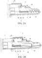
- FIG. 2A and FIG. 2B schematically illustrate the detergent box assembly as shown in FIG. 1A and FIG. 1B , where the top wall 21 of the outer box 2 is omitted to illustrate the internal structure of the detergent box assembly.
- FIG. 2A and FIG. 2B show that the inner box 1 is in the closed and open states, respectively.
- the inner box 1 can be driven to move outward from the accommodating cavity 20 in the opening direction D1 by the driving mechanism 3.
- the driving mechanism 3 is capable of independently driving the external connection terminal 4 to move in the opening direction D1 relative to the inner box 1, so that the external connection terminal 4 remains connected to the inner box 1.
- the external connection terminal 4 is restricted in the opening direction D1 and thus disconnected from the inner box 1.
- the driving mechanism 3 independently drives the external connection terminal 4 relative to the inner box 1 means that the force transmission path or the motion transmission path through which the driving mechanism 3 drives the external connection terminal 4 does not pass through the inner box 1.
- the driving mechanism 3 may directly drive the external connection terminal 4, or indirectly drive the external connection terminal 4 through a component other than the inner box 1.
- the external connection terminal 4 may be moved in the opening direction D1 by the driving mechanism 3 so as to move synchronously with the inner box 1 without disengaging from the inner box 1.
- the external connection terminal 4 is not disconnected from the inner box 1 until the inner box 1 moves in the opening direction D1 beyond its limit position of the opening stroke.
- the external connection terminal 4 is not driven to move outwards by the inner box 1 during the opening stroke of the inner box 1, but is driven independently of the inner box 1 by the driving mechanism 3. Compared to the situation where the external connection terminal 4 is driven by the inner box 1 and then moves outward therewith, the connection between the external connection terminal 4 and the inner box 1 will be more stable. This is particularly advantageous for the external connection terminal 4 used for forming an electrical connection with the inner box 1. Thus, it is necessary to prevent the situation that the connection between the inner box 1 and the external connection terminal 4 from becomes loose during the opening stroke of the inner box 1, resulting in an unreliable or ineffective electrical connection therebetween.
- connection between the inner box 1 and the external connection terminal 4 becomes loose and the inner box 1 is closed without ensuring a reconnection between the inner box 1 and the external connection terminal 4, it may cause the washing machine to malfunction.
- a stable and reliable electrical connection can be ensured between the inner box 1 and the external connection terminal 4. It may also provide support for implementation of specific functions, such as detection, when the inner box 2 is opened.
- the driving mechanism 3 may drive the external connection terminal 4 and the inner box 1 in parallel.
- the driving mechanism 3 may include a driving element 31 movably arranged relative to the outer box 2, and the driving element 31 may be respectively connected to the external connection terminal 4 and the inner box 1, so that when the driving element 31 moves, the external connection terminal 4 and the inner box 1 may be driven to synchronously move by the driving element 31.
- the driving mechanism 3 may be connected to the inner box 1 only by means of the external connection terminal 4 so as to indirectly drive the inner box 1 to move in the opening direction D1 by means of the external connection terminal 4. Therefore, the external connection terminal 4 is driven to push the inner box 1 to move outward from the accommodating cavity 20 in the opening direction D1 by the driving mechanism 3.
- the driving element 31 does not need to be directly connected to the inner box 1.
- the detergent box assembly may be convenient to use. For example, for cleaning or maintenance purposes, the inner box 1 can be fully withdrawn from the accommodating cavity 20. In this process, since the driving element 31 is not directly connected to the inner box 1, there is no need to additionally perform an operation of detaching or engaging the driving element 31 from/with the inner box 1.
- the structure of the detergent box assembly may be simplified.
- the detergent box assembly usually has only a small installation space. In this case, a more complicated structural design is often required to realize the automatic opening of the inner box 1.
- the external connection terminal 4 may be in a plug-in connection with the inner box 1, and the direction of the plug-in connection is parallel to the opening direction D 1.
- FIG. 2B schematically illustrates that inner box 1 is at its limit position of the opening stroke.
- the external connection terminal 4 is limited in the opening direction D1. If the inner box 1 continues to move in the opening direction D1, the plug-in connection between the inner box 1 and the external connection terminal 4 will be released, so that the external connection terminal 4 is disconnected from the inner box 1.
- the inner box 1 can be completely withdrawn from the accommodating cavity 20.
- the inner box 1 can be inserted into the accommodating cavity 20 in the closing direction D2 opposite to the opening direction D1.
- the inner box 1 can be re-inserted into the external connection terminal 4 in the closing direction D2.
- Such a plug-in connection between the external connection terminal 4 and the inner box 1 can facilitate the complete withdrawal of the inner box 1 from the accommodating cavity 20 and the reinstallation of the fully withdrawn inner box 1 into the accommodating cavity 20 without the need for additional operations.
- the driving mechanism 3 may include the driving element 31 movably arranged relative to the outer box 2, and the driving element 31 is connected to the external connection terminal 4 in a relatively immovable manner along the direction parallel to the opening direction D1.
- the driving element 31 may be fixed to the external connection terminal 4 by means of screws.
- the external connection terminal 4 will move accordingly. Further, the external connection terminal 4 can push the inner box 1 to move in the opening direction D1.
- the inner box 1 when the opened inner box 1 is inserted into the accommodating cavity 20 in the closing direction D2, the inner box 1 may push the external connection terminal 4 to move in the closing direction D2.
- the driving element 31 may be movable in the closing direction D2 together with the external connection terminal 4. Thus, the driving element 31 can be reset.
- the outer box 2 may be provided with a limit structure 23.
- the limit structure 23 may be configured to be capable of limiting the limit position of the driving element 31 moving in the opening direction D1 relative to the outer box 2, thereby indirectly limiting the limit position of the external connection terminal 4 moving in the opening direction D1 relative to the outer box 2.
- the limit structure 23 may be formed as a stopper at the upper side of the top wall 21, for example.
- the stopper may be configured to be capable of blocking the driving element 31 in front of the driving element 31 when the inner box 1 moves in the opening direction D1 beyond its limit position of the opening stroke.
- the limit structure 23 may be configured to be capable of limiting the limit position of the external connection terminal 4 moving in the opening direction D1 relative to the outer box 2, thereby indirectly limiting the limit position of the driving element 31 moving in the opening direction D1 relative to the outer box 2.
- the limit structure 23 may be formed as a stopper at the lower side of the top wall 21, which blocks the external connection terminal 4 in front of the external connection terminal 4 when the inner box 1 moves in the opening direction D1 beyond its limit position of the opening stroke.
- the driving element 31 may be configured as a rack, which may be arranged on the outer side of the outer box 2 facing away from the accommodating cavity 20.
- the detergent box assembly can be made more stable and reliable, and the configuration will help to reduce the volume of the outer box 2.
- the inner box 1 is configured to be automatically ejected by means of the driving mechanism 3
- the internal structure of the detergent box assembly tends to be more complicated.
- Providing the rack at the outer side of the outer box 2 helps to simplify the structure inside the outer box 2, which prevents interference between moving components.
- the rack may be arranged at the upper side of the top wall 21 of the outer box 2.
- the rack may be arranged particularly in the middle of the inner box 1 in the width direction perpendicular to the opening direction D1, so that the inner box 1 can be moved more stably relative to the outer box 2.
- a guide slot 24 extending along the opening direction D1 may be formed at the outer side of the outer box 2 facing away from the accommodating cavity 20.
- the rack may be slidably arranged in the guide slot 24.
- the guide slot 24 may be provided with a through hole 25, and the rack is connected to the external connection terminal 4 located in the accommodating cavity 20 through the through hole 25.
- the guide slot 24 and/or the through hole 25 may also serve as a limit structure 23.
- the rack abuts against the end of the guide slot 24 and/or the through hole 25 and thus is blocked, so that the movement of the rack in the opening direction D1 cannot be continued.
- the through hole 25 may limit the movement range of the driving element 31 at both ends, so that the length of the through hole 25 extending in the opening direction D1 may correspond to the length of the opening stroke of the inner box 1.
- the driving mechanism 3 may further include a damping gear 32 engaged with the rack.
- the damping gear 32 may be arranged at the outer side of the outer box 2 facing away from the accommodating cavity 20.
- the damping gear 32 may be arranged on the top wall 21 of the outer box 2.
- the damping gear 32 may be located next to the guide slot 24, and arranged roughly centered relative to the guide slot 24.
- the damping force generated by the damping gear 32 may be proportional to the rotational speed thereof.
- the damping gear 32 may be, for example, a hydraulic damping gear, a spring damping gear and a rubber damping gear.
- the driving mechanism 3 may also include an elastic element 33 used for providing a driving force to enable the inner box 1 to move outward in the opening direction D1 during the opening stroke of the inner box 1.
- the elastic element 33 may be arranged at the outer side of the outer box 2 facing away from the accommodating cavity 20. One end of the elastic element 33 is fixed to the rack, and the other end of the elastic element 33 is fixed to the outer box 2.
- the elastic element 33 may be implemented as a spring, and may also include components made of other elastic materials. For example, as shown in FIG. 1A and FIG. 2A , in the case where the inner box 1 is in a closed state, the elastic element 33 may be stretched and locked by a locking mechanism (not shown here) of the detergent box assembly.
- the elastic element 33 may contract and pull the driving element 31 to move in the opening direction D 1. Further, the driving element 31 drives the external connection terminal 4 and the inner box 1 to move in the opening direction D1. In this process, the elastic element 33 only needs to provide a force that can overcome a friction to push the external connection terminal 4 and the inner box 1, without the need to provide an additional force that can disconnect the external connection terminal 4 from the inner box 1. Thus, for example, the required deformation and/or elastic modulus of the elastic element 33 can be reduced accordingly. It contributes to improving the feasibility and reliability of opening the inner box 1 with the elastic force of the elastic element 33. As shown in FIG. 1B and FIG.
- the elastic element 33 when the inner box 1 is in an open state, the elastic element 33 may be in a loose state, for example.
- the external connection terminal 4 When a user pushes the inner box 1 to move towards the interior of the accommodating cavity 20 in the closing direction D2, the external connection terminal 4 may be pushed by the inner box 1 and thus drive the driving element 31 to move along the closing direction D2.
- the elastic element 33 By means of the driving element 31, the elastic element 33 can be reset to a stretched state and can be locked again by the locking mechanism. The force required to be provided by the user in the reset process may also be reduced accordingly.
- the driving mechanism 3 may also include a motor, which may be connected to the driving element 31.
- the motor may be rotated in response to the operation of a user so as to drive the driving element 31 to move.
- the driving element 31 may also include a screw rod and a sliding block.
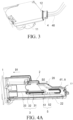
- FIG. 3 schematically illustrates some components of the detergent box assembly according to the exemplary embodiment of the present disclosure.
- the external connection terminal 4 is connected to the inner box 1.
- the inner box 1 may include, for example, an electrical device 11 and an internal connection terminal 12 for electrically connecting the electrical device 11 to the external connection terminal 4.
- the electrical device 11 may include, for example, a pump and/or a sensor.
- the internal connection terminal 12 may be configured to be capable of forming a plug-in connection with the external connection terminal 4 in the direction opposite to the opening direction D1.
- One end of the external connection terminal 4 may be connected to the internal connection terminal 12, and the other end of the external connection terminal 4 may be connected to a power supply device and/or a control device of the washing machine, for example.
- the other end of the external connection terminal 4 may be connected to a cable 40, and the cable 40 passes through the outer box 2 and is connected to the power supply device and/or the control device.
- the cable 40 may include a power cable and/or a communication cable.
- the cable 40 may be curlily stored in the accommodating cavity 20; in the process of opening the inner box 1, the external connection terminal 4 moves along the opening direction D1, so that the cable 40 can be unrolled under the traction of the external connection terminal 4.
- the external connection terminal 4 can still be electrically connected to the inner box 1 stably and reliably. Therefore, the electrical device 11 of the inner box 1 is still able to operate.
- the sensor in the inner box 1 can detect the amount of the added detergent and transmit the detection result to the control device, which can then notify the user of the detection result.
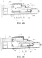
- FIG. 4A , FIG. 4B and FIG. 4C schematically illustrate the detergent box assembly according to the exemplary embodiment of the present disclosure, where the top wall 21 of the outer box 2 is omitted to illustrate the internal structure of the detergent box assembly.
- the driving mechanism 3 is also omitted in FIG. 4C .
- the detergent box assembly may further include a connecting piece 5, and the connecting piece 5 is connected to the driving element 31 and the external connection terminal 4 in a relatively immovable manner along the direction parallel to the opening direction D1.
- the driving element 31 is connected to the external connection terminal 4 by means of the connecting piece 5.
- FIG. 4A and FIG. 4B show that inner box 1 is in the closed and open states, respectively.
- the driving element 31 can drive the connecting piece 5 to move outwards in the opening direction D1.
- the connecting piece 5 can apply a driving force to the external connection terminal 4 in the opening direction D1 so as to enable the external connection terminal 4 to move synchronously with the inner box 1.
- FIG. 5 schematically illustrates some components of the detergent box assembly according to the exemplary embodiment of the present disclosure.
- FIG. 6 schematically illustrates a connecting piece 5 of the detergent box assembly according to the exemplary embodiment of the present disclosure.
- FIG. 7 schematically illustrates some components of the detergent box assembly as shown in FIG. 5 from different perspectives.
- the connecting piece 5 may include a limit housing 51, which is configured to be capable of limiting the external connection terminal 4 in the direction parallel to the opening direction D1.
- the connecting piece 5 may be fixedly connected to the external connection terminal 4 in the opening direction D1 by means of the limit housing 51.
- the limit housing 51 may circumferentially surround the external connection terminal 4 relative to the opening direction D1.
- the driving element 31 may be fixed to the connecting piece 5 by a threaded connection.
- a screw can pass through the driving element 31 and screwed into a threaded hole of the connecting piece 5 so as to fix the driving element 31 to the connecting piece 5, in particular to the limit housing 51.
- the connecting piece 5 may include, for example, a sheath 52 used for accommodating at least a partial section of the cable 40 connected to the external connection terminal 4.
- the sheath 52 may extend in the opening direction D1.
- the sheath 52 can restrain the section of the cable 40 adjacent to the external connection terminal 4, so that the section is retained within the sheath 52 even if being deformed, thereby preventing the section of the cable 40 adjacent to the external connection terminal 4 from being uncontrollably moved and deformed during the opening and closing of the inner box 1.
- the cable 40 can thereby be protected. It also helps to prevent the inner box 1 from being stuck due to the cable 40 during movement. For example, it can prevent the phenomenon that the curled cable 40 gets stuck between inner box 1 and outer box 2, causing the inner box 1 to be stuck during movement.
- the sheath 52 may in particular circumferentially surround the cable 40 relative to the opening direction D1. In other words, the sheath 52 can limit the cable 40 therein, so that the cable 40 will not leave the sheath 52 in any direction perpendicular to the opening direction D 1. Thus, it is possible to effectively limit the movement and deformation of the cable 40, and prevent the cable 40 from getting stuck between relatively moving components.
- the connecting piece 5 is particularly capable of achieving multiple functions in a simple and easy-to-install structure.
- the cross-sectional area of the sheath 52 may be smaller than that of the limit housing 51.
- the cross-sectional area of the sheath 52 is significantly smaller than that of the limit housing 51, for example, it may be less than half of the cross-sectional area of the limit housing 51.
- the sheath 52 having a smaller cross section can effectively reduce the deformation of the cable 40 accommodated therein.
- the limit housing 51 may include, for example, a first portion 511 and a second portion 512.
- the first portion 511 and the second portion 512 may have U-shaped cross sections.
- the first portion 511 and the second portion 512 are nested with each other, so that an opening of the first portion 511 is opposite to that of the second portion 512, and the two side walls of the first portion 511 are clamped by the two side walls of the second portion 512.
- the external connection terminal 4 is located between the first portion 511 and the second portion 512. This structure helps to prevent the external connection terminal 4 from being accidentally detached from the limit housing 51. As shown in FIG.
- the external connection terminal 4 may be configured to be mounted to the first portion 511 in the mounting direction D3 perpendicular to the opening direction D1 so as to be limited by the first portion 511 in the direction perpendicular to the mounting direction D3.
- a slot extending along the mounting direction D3 may be formed in the first portion 511, and the external connection terminal 4 may be inserted into the slot and be limited in the opening direction D1.
- the second portion 512 may be configured to be mounted to the first portion 511 in the mounting direction D3.
- the first portion 511 and the second portion 512 may be engaged with each other, for example, by a buckled connection.
- the first portion 511 can particularly be constructed as a one-piece component with the sheath 52.
- the connecting piece 5 By means of such a connecting piece 5, a stable and reliable connection between the connecting piece 5 and the external connection terminal 4 can be achieved in a simple manner.
- the assembling process between the external connection terminal 4 and the connecting piece 5 is simple and convenient.
- the second portion 512 may also be omitted.
- the connecting piece 5 may consist of the first portion 511 and the sheath 52.
- the sheath 52 may include a first wall 521 and a second wall 522 which are opposite to each other and extend in the opening direction D1, and the cable 40 is maintained between the first wall 521 and the second wall 522.
- the sheath 52 may further include at least one elastic arm 523 that extends from one of the first wall 521 and the second wall 522 to the other in a cantilevered manner.
- the elastic arm 523 may be configured to be able to undergo elastic deformation in the direction perpendicular to the opening direction D1.
- the at least one elastic arm 523 may include, for example, a plurality of elastic arms 523 spaced apart in the opening direction D1.
- the sheath 52 may further include a third wall opposite to the elastic arms 523, which extends in the opening direction D1 and connects the first wall 521 to the second wall 522.
- the cable 40 may press the elastic arms 523 from the outer sides of the elastic arms 523 so as to enter the sheath 52 by virtue of the elastic deformation of the elastic arms 523.
- the cable 40 can be installed inside the sheath 52 in a simple way without the need for additional components or tools.
- the distances between the elastic arms 523 and the other of the first wall 521 and the second wall 522 may be smaller than the diameter of the cable 40.
- the elastic arms 523 may retain the cable 40 within the sheath 52.
- the distance may be set to be greater than or equal to 0.
- the elastic arms 523 may extend from the first wall 521 to the second wall 522.
- Each of the elastic arms 523 may include a narrowed section abutted on to the first wall 521 and an expanded section distal from the first wall 521, where the narrowed section has a smaller cross-sectional area than the expanded section, which contributes to the elastic deformation of the elastic arms 523.
- the detergent box assembly further includes, for example, a deformable cable protector 6, and the cable protector 6 is configured to be capable of accommodating at least a partial section of the cable 40 connected to the external connection terminal 4.
- the cable protector 6 may be configured to deform synchronously with the movement of the external connection terminal 4 during the movement of the external connection terminal 4 in the opening direction D1 and/or the direction opposite to the opening direction D1.
- the cable protector 6 may limit the movement and deformation of the cable 40.
- the cable 40 can thereby be protected.
- the inner box 1 can be prevented from being stuck due to the cable 40 during movement.
- the inner box 1 may for example be provided with a recess 13 for accommodating the cable protector 6.
- the cable protector 6 may be located within the recess 13 when the inner box 1 is at the closed position. Thus, it is helpful to reduce the size of the detergent box assembly.
- the first end of the cable protector 6 may be kinetically coupled to the external connection terminal 4, and the second end of the cable protector 6 may be attached to the outer box 2.
- the first end of the cable protector 6 may be attached, for example, to the external connection terminal 4, or to the connecting piece 5.
- the first end of the cable protector 6 can move with the external connection terminal 4, so that the cable protector 6 can be deformed in synchronization with the movement of the external connection terminal 4.
- the cable protector 6 may be configured to be able to undergo telescopic deformation and/or bending deformation in synchronization with the movement of the external connection terminal 4.
- the cable protector 6 may include a corrugated pipe, a telescopic sleeve and a drag chain 61.
- the cable protector 6 is configured as the drag chain 61.
- the drag chain 61 includes a plurality of drag chain units 610. Every two adjacent drag chain units 610 in the plurality of drag chain units 610 are in a relatively rotatable connection with each other.
- the cable 40 passes through all the drag chain units 610 and extends within the drag chain 61.
- the drag chain 61 can be deformed in a predetermined manner, thereby restricting the movement and deformation of the cable 40, see FIG. 4A and FIG. 4B .
- the drag chain 61 may in particular be arranged such that every two adjacent drag chain units 610 in the plurality of drag chain units 610 are in a relatively rotatable connection with each other about a rotation axis extending in the vertical direction, which contributes to a compact structure of the detergent box assembly. In particular, there is no need to increase the height of the outer box 2.
- the plurality of drag chain units 610 are all located in the same horizontal plane, thereby preventing the drag chain 61 from interfering with the movement of the inner box 1. Especially when the inner box 1 is opened, the drag chain 61 will not sag below the inner box 1. It will be appreciated that it is acceptable for the drag chain 61 to have a slight sag.
- the plurality of drag chain units 610 may include a first end unit 611 and a second end unit 612 which are respectively located at both ends of the drag chain 61, and at least one intermediate unit 613 located between the first end unit 611 and the second end unit 612. It is particularly advantageous that the at least one intermediate unit 613 is supported only by the drag chain units 610 adjacent thereto.
- the first end unit 611 may be mounted to the connecting piece 5.
- the second end unit 612 may be mounted to the top wall 21 of the outer box 2.
- the intermediate unit 613 is arranged in a suspended manner above the inner box 1 without being in contact with the inner box 1 and the outer box 2.
- the drag chain 61 is arranged such that its drag chain units 610 are all located in the same horizontal plane, which helps to arrange the intermediate units 613 of the drag chain 61 in a suspended manner.
- the connecting piece 5 may include the sheath 52, and the first end of the drag chain 61 may be attached to the end of the sheath 52 far away from the external connection terminal 4.
- the sheath 52 may be provided as described above.
- the sheath 52 By using the sheath 52, the length of the drag chain 61 can be reduced, thereby helping to prevent the drag chain 61 from sagging.
- every two adjacent drag chain units 610 in the plurality of drag chain units 610 are in a relatively rotatable connection with each other about a rotation axis extending in the vertical direction, which is particularly advantageous to prevent the drag chain 61 from sagging.
- the two ends of the sheath 52 are respectively located in front and rear of a second end of the drag chain 61 in the opening direction D1.
- the end of the sheath 52 far away from the external connection terminal 4 is located in front of the second end of the drag chain 61 in the opening direction D 1. It is beneficial for preventing the drag chain 61 from sagging. With the help of the sheath 52, the relative positions of the two ends of the drag chain 61 during movement can be set as needed.
- a first end of the drag chain 61 may be attached to the limit housing 51 of the connecting piece 5 or to the external connection terminal 4, for example.
- the first end of the drag chain 61 will be located in front of the second end of the drag chain 61 in the opening direction D1.
- This arrangement will make it easier for the drag chain 61 to sag. In other words, this arrangement makes it difficult for the drag chain 61 to meet the requirements for the length of the cable 40 connected to the external connection terminal 4 without sagging.
- one end of the sheath 52 may be located at a first position in the closing direction D2 on the side facing the second end of the drag chain 61, and the other end of the sheath may be located at a second position in the closing direction D2 on the side facing away from the second end of the drag chain 61, the second position being located behind the first position in the opening direction D1, which helps to ensure that the drag chain 61 deforms in a predetermined manner.
- FIG. 8A and FIG. 8B schematically illustrate a detergent box assembly according to another exemplary embodiment of the present disclosure, where the cable protector 6 is configured as a corrugated pipe 62.
Landscapes
- Engineering & Computer Science (AREA)
- Textile Engineering (AREA)
- Detail Structures Of Washing Machines And Dryers (AREA)
Abstract
Description
- The present disclosure relates to the field of household appliances, and more particularly, to a detergent box assembly and a washing machine.
- In a household appliance, such as a washing machine, there may be a detergent box assembly, which includes an inner box for containing detergent, and an outer box for accommodating the inner box. The inner box can be manually opened by a user through pulling to add detergent.
- In order to facilitate the operation by a user, the inner box may also be set to be able to open automatically. The detergent box assembly further includes a connection terminal to provide electrical connections for elements in the inner box. The connection terminal is usually fixed to the outer box and connected to the inner box. When the inner box is opened, the inner box is disconnected from the connection terminal. Therefore, at the time of opening the inner box, a greater resistance needs to be overcome so that the inner box is disconnected from the connection terminal, which makes it difficult to achieve automatic opening of the inner box. In addition, it is necessary to ensure that the inner box is reconnected to the connection terminal when the user closes the inner box, otherwise the washing machine may not work properly. Moreover, in the opening and closing processes of the inner box, it is difficult to maintain the electrically conductive connection between the connection terminal and the inner box.
- At present, the detergent box assembly has disadvantages such as inconvenient operation, high difficulty of automatic opening, and unstable structure.
- It is an object of the embodiments of the present disclosure to provide an improved detergent box assembly and a washing machine so as to overcome at least one of the above-mentioned disadvantages in the related art.
- According to the first aspect of the present disclosure, an embodiment of the present disclosure provides a detergent box assembly. The detergent box assembly includes: an inner box for containing detergent, an outer box provided with an accommodating cavity for accommodating the inner box, a driving mechanism, and an external connection terminal detachably connected to the inner box so as to form an electrical connection with the inner box. During an opening stroke of the inner box, the inner box can be driven to move outward from the accommodating cavity in the opening direction by the driving mechanism; and the driving mechanism is capable of independently driving the external connection terminal to move in the opening direction relative to the inner box, so that the external connection terminal remains connected to the inner box. When the inner box moves in the opening direction beyond its limit position of the opening stroke, the external connection terminal is restricted in the opening direction and thus disconnected from the inner box.
- During the opening stroke of the inner box, the external connection terminal may be moved in the opening direction by the driving mechanism so as to move synchronously with the inner box without disengaging from the inner box, which means that in the process of opening the inner box, the driving force used for driving the inner box does not need to overcome the connection force between the external connection terminal and the inner box. It contributes in particular to the automatic opening of the inner box. Especially advantageous is that the external connection terminal is not driven to move outwards by the inner box during the opening stroke of the inner box, but is driven independently of the inner box by the driving mechanism. Compared to the situation where the external connection terminal is driven by the inner box and then moves outward therewith, the connection between the external connection terminal and the inner box will be more stable. This is particularly advantageous for the external connection terminal used for forming an electrical connection with the inner box. Therefore, even when the inner box is opened, a stable and reliable electrical connection can be ensured between the inner box and the external connection terminal.
- According to an alternative embodiment of the present disclosure, the driving mechanism may be connected to the inner box only by means of the external connection terminal so as to indirectly drive the inner box to move in the opening direction by means of the external connection terminal. A driving element does not need to be directly connected to the inner box. Thus, the detergent box assembly has a simplified structure, and is convenient to use.
- According to an alternative embodiment of the present disclosure, the external connection terminal may be in a plug-in connection with the inner box, and the direction of the plug-in connection is parallel to the opening direction. Thus, it may be convenient for the inner box to be completely withdrawn from the accommodating cavity and for the fully withdrawn inner box to be reinstalled into the accommodating cavity without the need for additional operations.
- According to an alternative embodiment of the present disclosure, the driving mechanism may include a driving element movably arranged relative to the outer box, and the driving element is connected to the external connection terminal in a relatively immovable manner along the direction parallel to the opening direction. Thus, it helps to simplify the structure of the detergent box assembly and makes the detergent box assembly easy to use.
- According to an alternative embodiment of the present disclosure, the outer box is provided with a limit structure. For example, the limit structure may be configured to be capable of limiting the limit position of the driving element moving in the opening direction relative to the outer box, thereby indirectly limiting the limit position of the external connection terminal moving in the opening direction relative to the outer box. Alternatively, the limit structure may be configured to be capable of limiting the limit position of the external connection terminal moving in the opening direction relative to the outer box, thereby indirectly limiting the limit position of the driving element moving in the opening direction relative to the outer box. Thus, the detergent box assembly can be easily used with a simple structure.
- According to an alternative embodiment of the present disclosure, the detergent box assembly may further include a connecting piece, and the connecting piece is connected to the driving element and the external connection terminal in a relatively immovable manner along the direction parallel to the opening direction. Thus, there is no need to complicate the structures of the driving element and the external connection terminal.
- According to an alternative embodiment of the present disclosure, the connecting piece may include a limit housing, which is configured to be capable of limiting the external connection terminal in the direction parallel to the opening direction. For example, the limit housing may circumferentially surround the external connection terminal relative to the opening direction. Thus, especially when the connection is made or released between the external connection terminal and the inner box, a stable and reliable connection between the connecting piece and the external connection terminal can be ensured.
- Alternatively, the connecting piece may include a sheath, which is used for accommodating at least a partial section of a cable connected to the external connection terminal, the sheath extending in the opening direction. For example, the sheath may circumferentially surround the cable relative to the opening direction. Thus, the sheath can protect the cable, and also can prevent the inner box from being stuck due to the cable during movement.
- According to an alternative embodiment of the present disclosure, in a cross section perpendicular to the opening direction, the cross-sectional area of the sheath may be smaller than that of the limit housing. The sheath having a smaller cross section can effectively reduce the deformation of the cable accommodated therein.
- According to an alternative embodiment of the present disclosure, the limit housing may include a first portion and a second portion. In a cross section perpendicular to the opening direction, the first portion and the second portion may have U-shaped cross sections. The first portion and the second portion are nested with each other, so that an opening of the first portion is opposite to that of the second portion, and the two side walls of the first portion are clamped by the two side walls of the second portion. The external connection terminal is located between the first portion and the second portion. For example, the external connection terminal may be configured to be mounted to the first portion in the mounting direction perpendicular to the opening direction so as to be limited by the first portion in the direction perpendicular to the mounting direction. For example, the second portion may be configured to be mounted to the first portion in the mounting direction perpendicular to the opening direction. The first portion can particularly be constructed as a one-piece component with the sheath. By means of such a connecting piece, a stable and reliable connection between the connecting piece and the external connection terminal can be achieved in a simple manner.
- According to an alternative embodiment of the present disclosure, the sheath may include a first wall and a second wall which are opposite to each other and extend in the opening direction, and the cable is maintained between the first wall and the second wall. The sheath may further include at least one elastic arm that extends from one of the first wall and the second wall to the other in a cantilevered manner. For example, the elastic arm may be configured to be able to undergo elastic deformation in the direction perpendicular to the opening direction. In the case where the elastic arm is not deformed, the distance between the elastic arm and the other of the first wall and the second wall may be smaller than the diameter of the cable. Thus, the cable can be installed inside the sheath in a simple way without the need for additional components or tools.
- According to an alternative embodiment of the present disclosure, the driving element may be configured as a rack, which may be arranged on the outer side of the outer box facing away from the accommodating cavity. Thus, the detergent box assembly can be made more stable and reliable, and the configuration will help to reduce the volume of the outer box.
- For example, a guide slot extending along the opening direction may be formed at the outer side of the outer box facing away from the accommodating cavity, and the rack is slidably arranged in the guide slot. The guide slot may be provided with a through hole, and the rack may be connected to the external connection terminal located in the accommodating cavity through the through hole. Thus, the inner box is ensured to be opened and closed stably and reliably.
- Alternatively, the driving mechanism may further include a damping gear engaged with the rack, and the damping gear may be arranged at the outer side of the outer box facing away from the accommodating cavity. Thus, the movement of the rack and the subsequent inner box can be made smoother.
- For example, the driving mechanism may also include an elastic element used for providing a driving force to enable the inner box to move outward in the opening direction during the opening stroke of the inner box. The elastic element may be arranged at the outer side of the outer box facing away from the accommodating cavity. One end of the elastic element is fixed to the rack, and the other end of the elastic element is fixed to the outer box. With the help of the elastic element, the inner box can be automatically opened with a simple structure.
- According to an alternative embodiment of the present disclosure, the detergent box assembly further includes a deformable cable protector, which may be configured to be capable of accommodating at least a partial section of the cable connected to the external connection terminal. The cable protector may be configured to deform synchronously with the movement of the external connection terminal during the movement of the external connection terminal in the opening direction and/or the direction opposite to the opening direction. The cable protector may limit the movement and deformation of the cable, so that the cable can be protected, and the inner box can be prevented from being stuck due to the cable during movement.
- For example, the cable protector may be configured to be able to undergo telescopic deformation and/or bending deformation in synchronization with the movement of the external connection terminal. The cable protector may include at least one of the following: a corrugated pipe, a telescopic sleeve, and a drag chain.
- One end of the cable protector is kinetically coupled to the external connection terminal, and the other end of the cable protector is attached to the outer box, which helps to ensure that the cable protector deforms in a predetermined manner.
- According to an alternative embodiment of the present disclosure, the cable protector is configured as the drag chain, which includes a plurality of drag chain units. For example, the drag chain may be arranged such that every two adjacent drag chain units in the plurality of drag chain units are in a relatively rotatable connection with each other about a rotation axis extending in the vertical direction, which contributes to a compact structure of the detergent box assembly. In particular, there is no need to increase the height of the outer box. Alternatively, the plurality of drag chain units are all located in the same horizontal plane, thereby preventing the drag chain from interfering with the movement of the inner box. Especially when the inner box is opened, the drag chain will not sag below the inner box.
- For example, the plurality of drag chain units may include a first end unit and a second end unit which are respectively located at both ends of the drag chain, and at least one intermediate unit located between the first end unit and the second end unit. The at least one intermediate unit may be supported only by the drag chain units adjacent thereto. In this way, the friction between the drag chain and the inner box or the outer box during movement can be avoided, thereby preventing abrasion and noise caused thereby.
- According to an alternative embodiment of the present disclosure, in the case where the inner box is at the closed position, the two ends of the sheath may be respectively located in front and rear of a second end of the drag chain in the opening direction; and in the case where the inner box is at the limit position of the opening stroke, the end of the sheath far away from the external connection terminal may be located in front of the second end of the drag chain in the opening direction. It is beneficial for preventing the drag chain from sagging. With the help of the sheath, the relative positions of the two ends of the drag chain during movement can be set as needed.
- According to an alternative embodiment of the present disclosure, one end of the sheath may be located at a first position in the closing direction on the side facing the second end of the drag chain, and the other end of the sheath may be located at a second position in the closing direction on the side facing away from the second end of the drag chain, the second position being located behind the first position in the opening direction, which helps to ensure that the drag chain deforms in a predetermined manner.
- According to an alternative embodiment of the present disclosure, the inner box may be provided with a recess for accommodating the cable protector. The cable protector may be located within the recess when the inner box is at the closed position. Thus, it is helpful to reduce the size of the detergent box assembly.
- According to an alternative embodiment of the present disclosure, the cable protector is arranged in a suspended manner above the inner box such that the cable protector does not come into contact with the inner box, which can prevent abrasion and noise caused by the friction of the cable protector on the inner box.
- According to the second aspect of the present disclosure, an embodiment of the present disclosure provides a washing machine, which includes the detergent box assembly according to the present disclosure.
- A better understanding of the principles, features and advantages of the present disclosure will be obtained by describing the present disclosure in more detail below with reference to the accompanying drawings. The drawings include:
-
FIG. 1A and FIG. 1B schematically illustrate a detergent box assembly according to an exemplary embodiment of the present disclosure; -
FIG. 2A and FIG. 2B schematically illustrate the detergent box assembly as shown inFIG. 1A and FIG. 1B ; -
FIG. 3 schematically illustrates some components of the detergent box assembly according to the exemplary embodiment of the present disclosure; -
FIG. 4A ,FIG. 4B, and FIG. 4C schematically illustrate the detergent box assembly according to the exemplary embodiment of the present disclosure; -
FIG. 5 schematically illustrates some components of the detergent box assembly according to the exemplary embodiment of the present disclosure; -
FIG. 6 schematically illustrates a connecting piece of the detergent box assembly according to the exemplary embodiment of the present disclosure; -
FIG. 7 schematically illustrates some components of the detergent box assembly as shown inFIG. 5 from different perspectives; and -
FIG. 8A and FIG. 8B schematically illustrate a detergent box assembly according to an exemplary embodiment of the present disclosure. -
- 1 Inner box
- 11 Electrical device
- 12 Internal connection terminal
- 2 Outer box
- 20 Accommodating cavity
- 21 Top wall
- 22 Lower box body
- 23 Limit structure
- 24 Guide slot
- 25 Through hole
- 3 Driving mechanism
- 31 Driving element
- 32 Damping gear
- 33 Elastic element
- 4 External connection terminal
- 40 Cable
- 5 Connecting piece
- 51 Limit housing
- 511 First portion
- 512 Second portion
- 52 Sheath
- 521 First wall
- 522 Second wall
- 523 Elastic arm
- 6 Cable protector
- 61 Drag chain
- 62 Corrugated pipe
- 610 Drag chain unit
- 611 First end unit
- 612 Second end unit
- 613 Intermediate unit
- In order to make the technical problems to be solved, technical solutions and beneficial technical effects of the present disclosure clearer, the present disclosure will be further described in detail below with reference to the accompanying drawings and a plurality of exemplary embodiments. It should be understood that the specific embodiments described herein are only intended to explain the present disclosure, rather than to limit the protection scope of the present disclosure.
- First of all, in order to facilitate understanding, returning to the description in the section of background, the detergent box assembly in the related art has problems such as inconvenient operation, high difficulty of automatic opening, and unstable structure.
- With respect to at least one of the above technical problems or other possible technical problems, an exemplary embodiment of the present disclosure provides a detergent box assembly. The detergent box assembly includes: an inner box for containing detergent, an outer box provided with an accommodating cavity for accommodating the inner box, a driving mechanism, and an external connection terminal detachably connected to the inner box so as to form an electrical connection with the inner box, where during an opening stroke of the inner box, the inner box can be driven to move outward from the accommodating cavity in the opening direction by the driving mechanism; the driving mechanism is capable of independently driving the external connection terminal to move in the opening direction relative to the inner box, so that the external connection terminal remains connected to the inner box; and when the inner box moves in the opening direction beyond its limit position of the opening stroke, the external connection terminal is restricted in the opening direction and thus disconnected from the inner box.
- In order to better understand the present disclosure, exemplary embodiments of the present disclosure will be described below with reference to the accompanying drawings.
- Before starting the detailed description, it should be pointed out that the directional terms used in the description process refer to the normal service conditions of household appliances for convenience of description, and cannot be understood as absolute limitations to the corresponding features.
-
FIG. 1A and FIG. 1B schematically illustrate a detergent box assembly according to an exemplary embodiment of the present disclosure. In this embodiment, the detergent box assembly may be applied to a washing machine. In other embodiments, detergent box assemblies according to the exemplary embodiments of the present disclosure may be applied to various household appliances, such as a dishwasher, and a washer and dryer combo. - As shown in
FIG. 1A and FIG. 1B , the detergent box assembly includes: aninner box 1 used for containing detergent, anouter box 2 provided with anaccommodating cavity 20 for accommodating theinner box 1, adriving mechanism 3, and anexternal connection terminal 4, which is detachably connected to theinner box 1 so as to form an electrical connection with theinner box 1. By means of theexternal connection terminal 4, an electrically conductive connection can be formed between theinner box 1 and other components of the washing machine, thereby transmitting power or communication signals, for example, between theinner box 1 and the other components. In order to ensure a stable and reliable electrical connection between theexternal connection terminal 4 and theinner box 1, a relatively firm physical connection is generally formed between theexternal connection terminal 4 and theinner box 1. Therefore, it is necessary to provide a greater force to disengage theexternal connection terminal 4 from theinner box 1.FIG. 1A shows that theinner box 1 is in a closed state, where theinner box 1 is located substantially completely within theaccommodating cavity 20. For example, in the case where theinner box 1 is in the closed state, the detergent contained in theinner box 1 may be rinsed into a drum of the washing machine so as to be used for washing the laundry.FIG. 1B shows that theinner box 1 is in an open state, where theinner box 1 is moved outward from theaccommodating cavity 20 so as to be partially exposed to the outside, thereby facilitating a user to add detergent into theinner box 1, for example. Theouter box 2 may include, for example, atop wall 21 and alower box body 22. A groove may be formed in thelower box body 22, and theinner box 1 is located inside the groove. Thetop wall 21 may cover thelower box body 22 so as to enclose theaccommodating cavity 20 together with thelower box body 22. InFIG. 1A , theexternal connection terminal 4 is not visible because it is hidden by thetop wall 21. -
FIG. 2A and FIG. 2B schematically illustrate the detergent box assembly as shown inFIG. 1A and FIG. 1B , where thetop wall 21 of theouter box 2 is omitted to illustrate the internal structure of the detergent box assembly.FIG. 2A and FIG. 2B show that theinner box 1 is in the closed and open states, respectively. - During an opening stroke of the
inner box 1, theinner box 1 can be driven to move outward from theaccommodating cavity 20 in the opening direction D1 by thedriving mechanism 3. Thedriving mechanism 3 is capable of independently driving theexternal connection terminal 4 to move in the opening direction D1 relative to theinner box 1, so that theexternal connection terminal 4 remains connected to theinner box 1. When theinner box 1 moves in the opening direction D1 beyond its limit position of the opening stroke, theexternal connection terminal 4 is restricted in the opening direction D1 and thus disconnected from theinner box 1. - "The
driving mechanism 3 independently drives theexternal connection terminal 4 relative to theinner box 1" means that the force transmission path or the motion transmission path through which thedriving mechanism 3 drives theexternal connection terminal 4 does not pass through theinner box 1. For example, thedriving mechanism 3 may directly drive theexternal connection terminal 4, or indirectly drive theexternal connection terminal 4 through a component other than theinner box 1. - During the opening stroke of the
inner box 1, theexternal connection terminal 4 may be moved in the opening direction D1 by thedriving mechanism 3 so as to move synchronously with theinner box 1 without disengaging from theinner box 1. Theexternal connection terminal 4 is not disconnected from theinner box 1 until theinner box 1 moves in the opening direction D1 beyond its limit position of the opening stroke. This makes that in the process of opening theinner box 1, the driving force used for driving theinner box 1 does not need to overcome the connection force between theexternal connection terminal 4 and theinner box 1. It contributes in particular to the automatic opening of theinner box 1. In particular, at the time of opening theinner box 1, there is no need to provide a relatively large initial actuation force to separate theexternal connection terminal 4 from theinner box 1, so the opening process ofinner box 1 is smoother. Especially advantageous is that theexternal connection terminal 4 is not driven to move outwards by theinner box 1 during the opening stroke of theinner box 1, but is driven independently of theinner box 1 by thedriving mechanism 3. Compared to the situation where theexternal connection terminal 4 is driven by theinner box 1 and then moves outward therewith, the connection between theexternal connection terminal 4 and theinner box 1 will be more stable. This is particularly advantageous for theexternal connection terminal 4 used for forming an electrical connection with theinner box 1. Thus, it is necessary to prevent the situation that the connection between theinner box 1 and theexternal connection terminal 4 from becomes loose during the opening stroke of theinner box 1, resulting in an unreliable or ineffective electrical connection therebetween. If the connection between theinner box 1 and theexternal connection terminal 4 becomes loose and theinner box 1 is closed without ensuring a reconnection between theinner box 1 and theexternal connection terminal 4, it may cause the washing machine to malfunction. According to the present disclosure, even when theinner box 1 is opened, a stable and reliable electrical connection can be ensured between theinner box 1 and theexternal connection terminal 4. It may also provide support for implementation of specific functions, such as detection, when theinner box 2 is opened. - As an example, the
driving mechanism 3 may drive theexternal connection terminal 4 and theinner box 1 in parallel. For example, thedriving mechanism 3 may include a drivingelement 31 movably arranged relative to theouter box 2, and the drivingelement 31 may be respectively connected to theexternal connection terminal 4 and theinner box 1, so that when the drivingelement 31 moves, theexternal connection terminal 4 and theinner box 1 may be driven to synchronously move by the drivingelement 31. - Alternatively, the
driving mechanism 3 may be connected to theinner box 1 only by means of theexternal connection terminal 4 so as to indirectly drive theinner box 1 to move in the opening direction D1 by means of theexternal connection terminal 4. Therefore, theexternal connection terminal 4 is driven to push theinner box 1 to move outward from theaccommodating cavity 20 in the opening direction D1 by thedriving mechanism 3. The drivingelement 31 does not need to be directly connected to theinner box 1. Thus, the detergent box assembly may be convenient to use. For example, for cleaning or maintenance purposes, theinner box 1 can be fully withdrawn from theaccommodating cavity 20. In this process, since the drivingelement 31 is not directly connected to theinner box 1, there is no need to additionally perform an operation of detaching or engaging the drivingelement 31 from/with theinner box 1. In addition, the structure of the detergent box assembly may be simplified. The detergent box assembly usually has only a small installation space. In this case, a more complicated structural design is often required to realize the automatic opening of theinner box 1. By connecting thedriving mechanism 3 to theinner box 1 only through theexternal connection terminal 4, the structure of the detergent box assembly can be simplified, and the volume of the detergent box assembly can be reduced. - For example, the
external connection terminal 4 may be in a plug-in connection with theinner box 1, and the direction of the plug-in connection is parallel to theopening direction D 1.FIG. 2B schematically illustrates thatinner box 1 is at its limit position of the opening stroke. Here, theexternal connection terminal 4 is limited in the opening direction D1. If theinner box 1 continues to move in the opening direction D1, the plug-in connection between theinner box 1 and theexternal connection terminal 4 will be released, so that theexternal connection terminal 4 is disconnected from theinner box 1. Thus, theinner box 1 can be completely withdrawn from theaccommodating cavity 20. Conversely, in the process of reinstalling the fully withdrawninner box 1 into theaccommodating cavity 20, theinner box 1 can be inserted into theaccommodating cavity 20 in the closing direction D2 opposite to the opening direction D1. In this process, theinner box 1 can be re-inserted into theexternal connection terminal 4 in the closing direction D2. Such a plug-in connection between theexternal connection terminal 4 and theinner box 1 can facilitate the complete withdrawal of theinner box 1 from theaccommodating cavity 20 and the reinstallation of the fully withdrawninner box 1 into theaccommodating cavity 20 without the need for additional operations. - Alternatively, the
driving mechanism 3 may include the drivingelement 31 movably arranged relative to theouter box 2, and the drivingelement 31 is connected to theexternal connection terminal 4 in a relatively immovable manner along the direction parallel to the opening direction D1. For example, the drivingelement 31 may be fixed to theexternal connection terminal 4 by means of screws. Thus, it helps to simplify the structure of the detergent box assembly and makes the detergent box assembly easy to use. Referring toFIG. 2A and FIG. 2B , in the case where the drivingelement 31 moves in the opening direction D1, theexternal connection terminal 4 will move accordingly. Further, theexternal connection terminal 4 can push theinner box 1 to move in the opening direction D1. Conversely, when the openedinner box 1 is inserted into theaccommodating cavity 20 in the closing direction D2, theinner box 1 may push theexternal connection terminal 4 to move in the closing direction D2. The drivingelement 31 may be movable in the closing direction D2 together with theexternal connection terminal 4. Thus, the drivingelement 31 can be reset. - According to an exemplary embodiment of the present disclosure, the
outer box 2 may be provided with alimit structure 23. For example, thelimit structure 23 may be configured to be capable of limiting the limit position of the drivingelement 31 moving in the opening direction D1 relative to theouter box 2, thereby indirectly limiting the limit position of theexternal connection terminal 4 moving in the opening direction D1 relative to theouter box 2. Thelimit structure 23 may be formed as a stopper at the upper side of thetop wall 21, for example. The stopper may be configured to be capable of blocking the drivingelement 31 in front of the drivingelement 31 when theinner box 1 moves in the opening direction D1 beyond its limit position of the opening stroke. - Alternatively or additionally, the
limit structure 23 may be configured to be capable of limiting the limit position of theexternal connection terminal 4 moving in the opening direction D1 relative to theouter box 2, thereby indirectly limiting the limit position of the drivingelement 31 moving in the opening direction D1 relative to theouter box 2. For example, thelimit structure 23 may be formed as a stopper at the lower side of thetop wall 21, which blocks theexternal connection terminal 4 in front of theexternal connection terminal 4 when theinner box 1 moves in the opening direction D1 beyond its limit position of the opening stroke. - As an example, the driving
element 31 may be configured as a rack, which may be arranged on the outer side of theouter box 2 facing away from theaccommodating cavity 20. Thus, the detergent box assembly can be made more stable and reliable, and the configuration will help to reduce the volume of theouter box 2. In the case where theinner box 1 is configured to be automatically ejected by means of thedriving mechanism 3, the internal structure of the detergent box assembly tends to be more complicated. Providing the rack at the outer side of theouter box 2 helps to simplify the structure inside theouter box 2, which prevents interference between moving components. For example, the rack may be arranged at the upper side of thetop wall 21 of theouter box 2. The rack may be arranged particularly in the middle of theinner box 1 in the width direction perpendicular to the opening direction D1, so that theinner box 1 can be moved more stably relative to theouter box 2. Referring toFIG. 1A and FIG. 1B , for example, aguide slot 24 extending along the opening direction D1 may be formed at the outer side of theouter box 2 facing away from theaccommodating cavity 20. The rack may be slidably arranged in theguide slot 24. Theguide slot 24 may be provided with a throughhole 25, and the rack is connected to theexternal connection terminal 4 located in theaccommodating cavity 20 through the throughhole 25. Theguide slot 24 and/or the throughhole 25 may also serve as alimit structure 23. That is, when theinner box 1 moves in the opening direction D1 beyond its limit position of the opening stroke, the rack abuts against the end of theguide slot 24 and/or the throughhole 25 and thus is blocked, so that the movement of the rack in the opening direction D1 cannot be continued. Alternatively, the throughhole 25 may limit the movement range of the drivingelement 31 at both ends, so that the length of the throughhole 25 extending in the opening direction D1 may correspond to the length of the opening stroke of theinner box 1. - Alternatively, the
driving mechanism 3 may further include a dampinggear 32 engaged with the rack. The dampinggear 32 may be arranged at the outer side of theouter box 2 facing away from theaccommodating cavity 20. For example, the dampinggear 32 may be arranged on thetop wall 21 of theouter box 2. The dampinggear 32 may be located next to theguide slot 24, and arranged roughly centered relative to theguide slot 24. In the process of the rack driving theinner box 1 to open, the dampinggear 32 engaged with the rack rotates, thereby generating a damping force. Thus, the movement of the rack and the subsequentinner box 1 can be made smoother. In the exemplary embodiment of the present disclosure, the damping force generated by the dampinggear 32 may be proportional to the rotational speed thereof. Therefore, the faster the movement speed of the rack, the faster the rotational speed of the dampinggear 32, and the greater the damping force generated, and vice versa. The dampinggear 32 may be, for example, a hydraulic damping gear, a spring damping gear and a rubber damping gear. - The
driving mechanism 3 may also include anelastic element 33 used for providing a driving force to enable theinner box 1 to move outward in the opening direction D1 during the opening stroke of theinner box 1. Theelastic element 33 may be arranged at the outer side of theouter box 2 facing away from theaccommodating cavity 20. One end of theelastic element 33 is fixed to the rack, and the other end of theelastic element 33 is fixed to theouter box 2. Theelastic element 33 may be implemented as a spring, and may also include components made of other elastic materials. For example, as shown inFIG. 1A andFIG. 2A , in the case where theinner box 1 is in a closed state, theelastic element 33 may be stretched and locked by a locking mechanism (not shown here) of the detergent box assembly. In the case where the locking mechanism is unlocked, theelastic element 33 may contract and pull the drivingelement 31 to move in theopening direction D 1. Further, the drivingelement 31 drives theexternal connection terminal 4 and theinner box 1 to move in the opening direction D1. In this process, theelastic element 33 only needs to provide a force that can overcome a friction to push theexternal connection terminal 4 and theinner box 1, without the need to provide an additional force that can disconnect theexternal connection terminal 4 from theinner box 1. Thus, for example, the required deformation and/or elastic modulus of theelastic element 33 can be reduced accordingly. It contributes to improving the feasibility and reliability of opening theinner box 1 with the elastic force of theelastic element 33. As shown inFIG. 1B andFIG. 2B , when theinner box 1 is in an open state, theelastic element 33 may be in a loose state, for example. When a user pushes theinner box 1 to move towards the interior of theaccommodating cavity 20 in the closing direction D2, theexternal connection terminal 4 may be pushed by theinner box 1 and thus drive the drivingelement 31 to move along the closing direction D2. By means of the drivingelement 31, theelastic element 33 can be reset to a stretched state and can be locked again by the locking mechanism. The force required to be provided by the user in the reset process may also be reduced accordingly. - In the exemplary embodiment of the present disclosure, the
driving mechanism 3 may also include a motor, which may be connected to the drivingelement 31. For example, the motor may be rotated in response to the operation of a user so as to drive the drivingelement 31 to move. The drivingelement 31 may also include a screw rod and a sliding block. -
FIG. 3 schematically illustrates some components of the detergent box assembly according to the exemplary embodiment of the present disclosure. InFIG. 3 , theexternal connection terminal 4 is connected to theinner box 1. Theinner box 1 may include, for example, anelectrical device 11 and aninternal connection terminal 12 for electrically connecting theelectrical device 11 to theexternal connection terminal 4. Theelectrical device 11 may include, for example, a pump and/or a sensor. Theinternal connection terminal 12 may be configured to be capable of forming a plug-in connection with theexternal connection terminal 4 in the direction opposite to the opening direction D1. One end of theexternal connection terminal 4 may be connected to theinternal connection terminal 12, and the other end of theexternal connection terminal 4 may be connected to a power supply device and/or a control device of the washing machine, for example. For example, the other end of theexternal connection terminal 4 may be connected to acable 40, and thecable 40 passes through theouter box 2 and is connected to the power supply device and/or the control device. Thecable 40 may include a power cable and/or a communication cable. By means of theexternal connection terminal 4, electric power can be supplied to theelectrical device 11 in theinner box 1. Alternatively or additionally, by means of theexternal connection terminal 4, for example, a communication connection may be provided between theelectrical device 11 and the control device. Referring toFIG. 2A and FIG. 2B , in the closed state of theinner box 1, thecable 40 may be curlily stored in theaccommodating cavity 20; in the process of opening theinner box 1, theexternal connection terminal 4 moves along the opening direction D1, so that thecable 40 can be unrolled under the traction of theexternal connection terminal 4. In the case where theinner box 1 is opened, theexternal connection terminal 4 can still be electrically connected to theinner box 1 stably and reliably. Therefore, theelectrical device 11 of theinner box 1 is still able to operate. For example, when theinner box 1 is opened to add the detergent, the sensor in theinner box 1 can detect the amount of the added detergent and transmit the detection result to the control device, which can then notify the user of the detection result. -
FIG. 4A ,FIG. 4B and FIG. 4C schematically illustrate the detergent box assembly according to the exemplary embodiment of the present disclosure, where thetop wall 21 of theouter box 2 is omitted to illustrate the internal structure of the detergent box assembly. For the sake of clarity, thedriving mechanism 3 is also omitted inFIG. 4C . - In this embodiment, the detergent box assembly may further include a connecting
piece 5, and the connectingpiece 5 is connected to the drivingelement 31 and theexternal connection terminal 4 in a relatively immovable manner along the direction parallel to the opening direction D1. In other words, the drivingelement 31 is connected to theexternal connection terminal 4 by means of the connectingpiece 5. Thus, there is no need to complicate the structures of the drivingelement 31 and theexternal connection terminal 4. In particular, the concept of the present disclosure can be applied without changing the configuration of the existingexternal connection terminal 4. -
FIG. 4A andFIG. 4B show thatinner box 1 is in the closed and open states, respectively. During the opening stroke of theinner box 1, that is, in the process of moving from the state as shown inFIG. 4A to the state as shown inFIG. 4B , the drivingelement 31 can drive the connectingpiece 5 to move outwards in the opening direction D1. Thus, the connectingpiece 5 can apply a driving force to theexternal connection terminal 4 in the opening direction D1 so as to enable theexternal connection terminal 4 to move synchronously with theinner box 1. As shown inFIG. 4C , when theinner box 1 moves along the opening direction D1 to its limit position of the opening stroke, theinner box 1 can continue to move along the opening direction D1, and theexternal connection terminal 4 and the connectingpiece 5 are limited and thus do not continue to move along theopening direction D 1. Therefore, theexternal connection terminal 4 is disengaged from theinner box 1. -
FIG. 5 schematically illustrates some components of the detergent box assembly according to the exemplary embodiment of the present disclosure.FIG. 6 schematically illustrates a connectingpiece 5 of the detergent box assembly according to the exemplary embodiment of the present disclosure.FIG. 7 schematically illustrates some components of the detergent box assembly as shown inFIG. 5 from different perspectives. - As shown in
FIG. 5 and FIG. 6 , the connectingpiece 5 may include alimit housing 51, which is configured to be capable of limiting theexternal connection terminal 4 in the direction parallel to the opening direction D1. The connectingpiece 5 may be fixedly connected to theexternal connection terminal 4 in the opening direction D1 by means of thelimit housing 51. In particular, thelimit housing 51 may circumferentially surround theexternal connection terminal 4 relative to the opening direction D1. Thus, especially when the connection is made or released between theexternal connection terminal 4 and theinner box 1, a stable and reliable connection between the connectingpiece 5 and theexternal connection terminal 4 can be ensured. - Alternatively, the driving
element 31 may be fixed to the connectingpiece 5 by a threaded connection. For example, a screw can pass through the drivingelement 31 and screwed into a threaded hole of the connectingpiece 5 so as to fix the drivingelement 31 to the connectingpiece 5, in particular to thelimit housing 51. - The connecting
piece 5 may include, for example, asheath 52 used for accommodating at least a partial section of thecable 40 connected to theexternal connection terminal 4. Thesheath 52 may extend in the opening direction D1. Thesheath 52 can restrain the section of thecable 40 adjacent to theexternal connection terminal 4, so that the section is retained within thesheath 52 even if being deformed, thereby preventing the section of thecable 40 adjacent to theexternal connection terminal 4 from being uncontrollably moved and deformed during the opening and closing of theinner box 1. Thecable 40 can thereby be protected. It also helps to prevent theinner box 1 from being stuck due to thecable 40 during movement. For example, it can prevent the phenomenon that the curledcable 40 gets stuck betweeninner box 1 andouter box 2, causing theinner box 1 to be stuck during movement. Thesheath 52 may in particular circumferentially surround thecable 40 relative to the opening direction D1. In other words, thesheath 52 can limit thecable 40 therein, so that thecable 40 will not leave thesheath 52 in any direction perpendicular to theopening direction D 1. Thus, it is possible to effectively limit the movement and deformation of thecable 40, and prevent thecable 40 from getting stuck between relatively moving components. The connectingpiece 5 is particularly capable of achieving multiple functions in a simple and easy-to-install structure. - In a cross section perpendicular to the opening direction D1, the cross-sectional area of the
sheath 52 may be smaller than that of thelimit housing 51. Referring toFIG. 5 and FIG. 6 , the cross-sectional area of thesheath 52 is significantly smaller than that of thelimit housing 51, for example, it may be less than half of the cross-sectional area of thelimit housing 51. Thesheath 52 having a smaller cross section can effectively reduce the deformation of thecable 40 accommodated therein. - Referring to
FIG. 6 , thelimit housing 51 may include, for example, afirst portion 511 and asecond portion 512. In a cross section perpendicular to the opening direction D1, thefirst portion 511 and thesecond portion 512 may have U-shaped cross sections. Thefirst portion 511 and thesecond portion 512 are nested with each other, so that an opening of thefirst portion 511 is opposite to that of thesecond portion 512, and the two side walls of thefirst portion 511 are clamped by the two side walls of thesecond portion 512. Thus, the strength of thelimit housing 51 can be enhanced. Theexternal connection terminal 4 is located between thefirst portion 511 and thesecond portion 512. This structure helps to prevent theexternal connection terminal 4 from being accidentally detached from thelimit housing 51. As shown inFIG. 7 , for example, theexternal connection terminal 4 may be configured to be mounted to thefirst portion 511 in the mounting direction D3 perpendicular to the opening direction D1 so as to be limited by thefirst portion 511 in the direction perpendicular to the mounting direction D3. For example, a slot extending along the mounting direction D3 may be formed in thefirst portion 511, and theexternal connection terminal 4 may be inserted into the slot and be limited in the opening direction D1. Thesecond portion 512 may be configured to be mounted to thefirst portion 511 in the mounting direction D3. Thefirst portion 511 and thesecond portion 512 may be engaged with each other, for example, by a buckled connection. Thefirst portion 511 can particularly be constructed as a one-piece component with thesheath 52. By means of such a connectingpiece 5, a stable and reliable connection between the connectingpiece 5 and theexternal connection terminal 4 can be achieved in a simple manner. The assembling process between theexternal connection terminal 4 and the connectingpiece 5 is simple and convenient. In other embodiments, thesecond portion 512 may also be omitted. For example, the connectingpiece 5 may consist of thefirst portion 511 and thesheath 52. - As shown in
FIG. 6 , thesheath 52 may include afirst wall 521 and asecond wall 522 which are opposite to each other and extend in the opening direction D1, and thecable 40 is maintained between thefirst wall 521 and thesecond wall 522. Thesheath 52 may further include at least oneelastic arm 523 that extends from one of thefirst wall 521 and thesecond wall 522 to the other in a cantilevered manner. Theelastic arm 523 may be configured to be able to undergo elastic deformation in the direction perpendicular to the opening direction D1. The at least oneelastic arm 523 may include, for example, a plurality ofelastic arms 523 spaced apart in the opening direction D1. Alternatively, thesheath 52 may further include a third wall opposite to theelastic arms 523, which extends in the opening direction D1 and connects thefirst wall 521 to thesecond wall 522. Thecable 40 may press theelastic arms 523 from the outer sides of theelastic arms 523 so as to enter thesheath 52 by virtue of the elastic deformation of theelastic arms 523. Thus, thecable 40 can be installed inside thesheath 52 in a simple way without the need for additional components or tools. In the case where theelastic arms 523 are not deformed, the distances between theelastic arms 523 and the other of thefirst wall 521 and thesecond wall 522 may be smaller than the diameter of thecable 40. Thus, theelastic arms 523 may retain thecable 40 within thesheath 52. The distance may be set to be greater than or equal to 0. As an example, as shown inFIG. 6 , theelastic arms 523 may extend from thefirst wall 521 to thesecond wall 522. Each of theelastic arms 523 may include a narrowed section abutted on to thefirst wall 521 and an expanded section distal from thefirst wall 521, where the narrowed section has a smaller cross-sectional area than the expanded section, which contributes to the elastic deformation of theelastic arms 523. - Returning to
FIG. 4A andFIG. 4B , the detergent box assembly further includes, for example, a deformable cable protector 6, and the cable protector 6 is configured to be capable of accommodating at least a partial section of thecable 40 connected to theexternal connection terminal 4. The cable protector 6 may be configured to deform synchronously with the movement of theexternal connection terminal 4 during the movement of theexternal connection terminal 4 in the opening direction D1 and/or the direction opposite to the opening direction D1. The cable protector 6 may limit the movement and deformation of thecable 40. Thecable 40 can thereby be protected. In addition, theinner box 1 can be prevented from being stuck due to thecable 40 during movement. - The
inner box 1 may for example be provided with arecess 13 for accommodating the cable protector 6. The cable protector 6 may be located within therecess 13 when theinner box 1 is at the closed position. Thus, it is helpful to reduce the size of the detergent box assembly. - Referring to
FIG. 4A andFIG. 4B , the first end of the cable protector 6 may be kinetically coupled to theexternal connection terminal 4, and the second end of the cable protector 6 may be attached to theouter box 2. The first end of the cable protector 6 may be attached, for example, to theexternal connection terminal 4, or to the connectingpiece 5. Thus, the first end of the cable protector 6 can move with theexternal connection terminal 4, so that the cable protector 6 can be deformed in synchronization with the movement of theexternal connection terminal 4. By attaching the second end of the cable protector 6 to theouter box 2, it helps to ensure that the cable protector 6 is deformed in a predetermined manner. In the processes of the opening and closing of theinner box 1, the cable protector 6 is always positioned within theaccommodating cavity 20. - For example, the cable protector 6 may be configured to be able to undergo telescopic deformation and/or bending deformation in synchronization with the movement of the
external connection terminal 4. Alternatively, the cable protector 6 may include a corrugated pipe, a telescopic sleeve and adrag chain 61. - Here, it is shown by way of example that the cable protector 6 is configured as the
drag chain 61. Thedrag chain 61 includes a plurality ofdrag chain units 610. Every two adjacentdrag chain units 610 in the plurality ofdrag chain units 610 are in a relatively rotatable connection with each other. Thecable 40 passes through all thedrag chain units 610 and extends within thedrag chain 61. In the processes of the opening and closing of theinner box 1, thedrag chain 61 can be deformed in a predetermined manner, thereby restricting the movement and deformation of thecable 40, seeFIG. 4A andFIG. 4B . Thedrag chain 61 may in particular be arranged such that every two adjacentdrag chain units 610 in the plurality ofdrag chain units 610 are in a relatively rotatable connection with each other about a rotation axis extending in the vertical direction, which contributes to a compact structure of the detergent box assembly. In particular, there is no need to increase the height of theouter box 2. Alternatively, the plurality ofdrag chain units 610 are all located in the same horizontal plane, thereby preventing thedrag chain 61 from interfering with the movement of theinner box 1. Especially when theinner box 1 is opened, thedrag chain 61 will not sag below theinner box 1. It will be appreciated that it is acceptable for thedrag chain 61 to have a slight sag. - The plurality of
drag chain units 610 may include afirst end unit 611 and asecond end unit 612 which are respectively located at both ends of thedrag chain 61, and at least oneintermediate unit 613 located between thefirst end unit 611 and thesecond end unit 612. It is particularly advantageous that the at least oneintermediate unit 613 is supported only by thedrag chain units 610 adjacent thereto. For example, referring toFIG. 5 , thefirst end unit 611 may be mounted to the connectingpiece 5. Thesecond end unit 612 may be mounted to thetop wall 21 of theouter box 2. Theintermediate unit 613 is arranged in a suspended manner above theinner box 1 without being in contact with theinner box 1 and theouter box 2. Thus, it is possible to prevent thedrag chain 61 from rubbing against theinner box 1 or theouter box 2 during movement, thereby preventing abrasion and noise caused thereby. Thedrag chain 61 is arranged such that itsdrag chain units 610 are all located in the same horizontal plane, which helps to arrange theintermediate units 613 of thedrag chain 61 in a suspended manner. - Alternatively, the connecting
piece 5 may include thesheath 52, and the first end of thedrag chain 61 may be attached to the end of thesheath 52 far away from theexternal connection terminal 4. Thesheath 52 may be provided as described above. By using thesheath 52, the length of thedrag chain 61 can be reduced, thereby helping to prevent thedrag chain 61 from sagging. In this case, every two adjacentdrag chain units 610 in the plurality ofdrag chain units 610 are in a relatively rotatable connection with each other about a rotation axis extending in the vertical direction, which is particularly advantageous to prevent thedrag chain 61 from sagging. - Referring to
FIG. 4A , in the case where theinner box 1 is at the closed position, the two ends of thesheath 52 are respectively located in front and rear of a second end of thedrag chain 61 in the opening direction D1. Referring toFIG. 4C , in the case where theinner box 1 is at the limit position of the opening stroke, the end of thesheath 52 far away from theexternal connection terminal 4 is located in front of the second end of thedrag chain 61 in theopening direction D 1. It is beneficial for preventing thedrag chain 61 from sagging. With the help of thesheath 52, the relative positions of the two ends of thedrag chain 61 during movement can be set as needed. In the absence of thesheath 52 in the connectingpiece 5, a first end of thedrag chain 61 may be attached to thelimit housing 51 of the connectingpiece 5 or to theexternal connection terminal 4, for example. When theinner box 1 is at the closed position and at the limit position of the opening stroke, the first end of thedrag chain 61 will be located in front of the second end of thedrag chain 61 in the opening direction D1. This arrangement will make it easier for thedrag chain 61 to sag. In other words, this arrangement makes it difficult for thedrag chain 61 to meet the requirements for the length of thecable 40 connected to theexternal connection terminal 4 without sagging. - Referring to
FIG. 5 and FIG. 7 , one end of thesheath 52 may be located at a first position in the closing direction D2 on the side facing the second end of thedrag chain 61, and the other end of the sheath may be located at a second position in the closing direction D2 on the side facing away from the second end of thedrag chain 61, the second position being located behind the first position in the opening direction D1, which helps to ensure that thedrag chain 61 deforms in a predetermined manner. -
FIG. 8A and FIG. 8B schematically illustrate a detergent box assembly according to another exemplary embodiment of the present disclosure, where the cable protector 6 is configured as a corrugated pipe 62. - Although specific implementation schemes have been described above, these implementation schemes are not intended to limit the scope provided in the present disclosure, even where only a single implementation scheme is described with respect to particular features. The examples of features provided in the present disclosure are intended for illustrative purposes rather than limiting, unless stated differently. In a specific implementation, multiple features may be combined with each other according to actual needs, where technically feasible. In particular, the features in the different embodiments may also be combined with one another. Various replacements, changes, and modifications may also be contemplated without departing from the spirit and scope of the present disclosure.
Claims (18)
- A detergent box assembly, comprising:an inner box (1), used for containing detergent;an outer box (2), provided with an accommodating cavity (20) for accommodating the inner box (1);a driving mechanism (3); andan external connection terminal (4), which is detachably connected to the inner box (1) so as to form an electrical connection with the inner box (1), whereinduring an opening stroke of the inner box (1), the inner box (1) is allowed to be driven to move outward from the accommodating cavity (20) in the opening direction by the driving mechanism (3); the driving mechanism (3) is capable of independently driving the external connection terminal (4) to move in the opening direction relative to the inner box (1), so that the external connection terminal (4) remains connected to the inner box (1); andwhen the inner box (1) moves in the opening direction beyond its limit position of the opening stroke, the external connection terminal (4) is restricted in the opening direction and thus disconnected from the inner box (1).
- The detergent box assembly according to claim 1, wherein
the driving mechanism (3) is connected to the inner box (1) only by means of the external connection terminal (4) so as to indirectly drive the inner box (1) to move in the opening direction by means of the external connection terminal (4). - The detergent box assembly according to claim 1 or 2, wherein
the external connection terminal (4) is in a plug-in connection with the inner box (1), and the direction of the plug-in connection is parallel to the opening direction. - The detergent box assembly according to any one of claims 1-3, wherein
the driving mechanism (3) comprises a driving element (31) movably arranged relative to the outer box (2), and the driving element (31) is connected to the external connection terminal (4) in a relatively immovable manner along the direction parallel to the opening direction. - The detergent box assembly according to claim 4, whereinthe outer box (2) is provided with a limit structure (23), whereinthe limit structure (23) is configured to be capable of limiting the limit position of the driving element (31) moving in the opening direction relative to the outer box (2), indirectly limiting the limit position of the external connection terminal (4) moving in the opening direction relative to the outer box (2); orthe limit structure (23) is configured to be capable of limiting the limit position of the external connection terminal (4) moving in the opening direction relative to the outer box (2), indirectly limiting the limit position of the driving element (31) moving in the opening direction relative to the outer box (2).
- The detergent box assembly according to claim 4 or 5, wherein
the detergent box assembly further comprises a connecting piece (5), and the connecting piece (5) is connected to the driving element (31) and the external connection terminal (4) in a relatively immovable manner along the direction parallel to the opening direction. - The detergent box assembly according to claim 6, wherein
the connecting piece (5) comprises at least one of the following:a limit housing (51), configured to be capable of limiting the external connection terminal (4) in the direction parallel to the opening direction; anda sheath (52), used for accommodating at least a partial section of a cable (40) connected to the external connection terminal (4), the sheath (52) extending in the opening direction. - The detergent box assembly according to claim 7, whereinin a cross section perpendicular to the opening direction, the cross-sectional area of the sheath (52) is smaller than that of the limit housing (51); and/orthe limit housing (51) circumferentially surrounds the external connection terminal (4) relative to the opening direction; and/orthe sheath (52) circumferentially surrounds the cable (40) relative to the opening direction.
- The detergent box assembly according to claim 7 or 8, whereinthe limit housing (51) comprises a first portion (511) and a second portion (512), wherein in a cross section perpendicular to the opening direction, the first portion (511) and the second portion (512) have U-shaped cross sections, and the first portion (511) and the second portion (512) are nested with each other, so that an opening of the first portion (511) is opposite to that of the second portion (512), and the two side walls of the first portion (511) are clamped by the two side walls of the second portion (512), whereinthe external connection terminal (4) is located between the first portion (511) and the second portion (512); and/orthe external connection terminal (4) is configured to be mounted to the first portion (511) in the mounting direction perpendicular to the opening direction so as to be limited by the first portion (511) in the direction perpendicular to the mounting direction; and/orthe second portion (512) is configured to be mounted to the first portion (511) in the mounting direction perpendicular to the opening direction; and/orthe first portion (511) and the sheath (52) are constructed as a one-piece component.
- The detergent box assembly according to any one of claims 7-9, whereinthe sheath (52) comprises a first wall (521) and a second wall (522) which are opposite to each other and extend in the opening direction, the cable (40) being maintained between the first wall (521) and the second wall (522); the sheath (52) further comprises at least one elastic arm (523) that extends from one of the first wall (521) and the second wall (522) to the other in a cantilevered manner, whereinthe elastic arm (523) is configured to be able to undergo elastic deformation in the direction perpendicular to the opening direction; and/orin the case where the elastic arm (523) is not deformed, the distance between the elastic arm (523) and the other of the first wall (521) and the second wall (522) is smaller than the diameter of the cable (40).
- The detergent box assembly according to any one of claims 4-10, whereinthe driving element (31) is configured as a rack, which is arranged on the outer side of the outer box (2) facing away from the accommodating cavity (20), whereina guide slot (24) extending along the opening direction is formed at the outer side of the outer box (2) facing away from the accommodating cavity (20), the rack is slidably arranged in the guide slot (24), the guide slot (24) is provided with a through hole (25), and the rack is connected to the external connection terminal (4) located in the accommodating cavity (20) through the through hole (25); and/orthe driving mechanism (3) further comprises a damping gear (32) engaged with the rack, and the damping gear (32) is arranged at the outer side of the outer box (2) facing away from the accommodating cavity (20); and/orthe driving mechanism (3) also comprises an elastic element (33) used for providing a driving force to enable the inner box (1) to move outward in the opening direction during the opening stroke of the inner box (1), wherein the elastic element (33) is arranged at the outer side of the outer box (2) facing away from the accommodating cavity (20), one end of the elastic element (33) is fixed to the rack, and the other end of the elastic element (33) is fixed to the outer box (2).
- The detergent box assembly according to any one of claims 1-11, wherein
the detergent box assembly further comprises a deformable cable protector (6), and the cable protector (6) is configured to be capable of accommodating at least a partial section of the cable (40) connected to the external connection terminal (4); and the cable protector (6) is configured to deform synchronously with the movement of the external connection terminal (4) during the movement of the external connection terminal (4) in the opening direction and/or the direction opposite to the opening direction. - The detergent box assembly according to claim 12, whereinthe cable protector (6) is configured to be able to undergo telescopic deformation and/or bending deformation in synchronization with the movement of the external connection terminal (4); and/orone end of the cable protector (6) is kinetically coupled to the external connection terminal (4), and the other end of the cable protector (6) is attached to the outer box (2); and/orthe cable protector (6) comprises at least one of the following: a corrugated pipe, a telescopic sleeve, and a drag chain (61).
- The detergent box assembly according to any one of claims 11-13, whereinthe cable protector (6) is configured as the drag chain (61), and the drag chain (61) comprises a plurality of drag chain units, whereinthe drag chain (61) is arranged such that every two adjacent drag chain units in the plurality of drag chain units are in a relatively rotatable connection with each other about a rotation axis extending in the vertical direction; and/orthe plurality of drag chain units are all located in the same horizontal plane; and/orthe plurality of drag chain units comprise a first end unit (611) and a second end unit (612) which are respectively located at both ends of the drag chain (61), and at least one intermediate unit (613) located between the first end unit (611) and the second end unit (612), the at least one intermediate unit (613) being supported only by the drag chain units adjacent thereto.
- The detergent box assembly according to any one of claims 12-14, whereinin the case where the inner box (1) is at the closed position, the two ends of the sheath (52) are respectively located in front and rear of a second end of the drag chain (61) in the opening direction; andin the case where the inner box (1) is at the limit position of the opening stroke, the end of the sheath (52) far away from the external connection terminal (4) is located in front of the second end of the drag chain (61) in the opening direction.
- The detergent box assembly according to any one of claims 12-15, wherein
one end of the sheath (52) is located at a first position in the closing direction on the side facing the second end of the drag chain (61), and the other end of the sheath (52) is located at a second position in the closing direction on the side facing away from the second end of the drag chain (61), the second position being located behind the first position in the opening direction. - The detergent box assembly according to any one of claims 12-16, whereinthe inner box (1) is provided with a recess (13) for accommodating the cable protector (6), wherein the cable protector (6) is located within the recess (13) when the inner box (1) is at the closed position; and/orthe cable protector (6) is arranged in a suspended manner above the inner box (1) such that the cable protector (6) does not come into contact with the inner box (1).
- A washing machine, wherein the washing machine comprises the detergent box assembly according to any one of claims 1-17.
Applications Claiming Priority (3)
| Application Number | Priority Date | Filing Date | Title |
|---|---|---|---|
| CN202310805131.6A CN119221258A (en) | 2023-06-30 | 2023-06-30 | Detergent box assembly and washing machine |
| CN202310792265.9A CN119221256A (en) | 2023-06-30 | 2023-06-30 | Detergent box assembly and washing machine |
| CN202310800179.8A CN119221257A (en) | 2023-06-30 | 2023-06-30 | Detergent box assembly and washing machine |
Publications (1)
| Publication Number | Publication Date |
|---|---|
| EP4484633A1 true EP4484633A1 (en) | 2025-01-01 |
Family
ID=91027143
Family Applications (1)
| Application Number | Title | Priority Date | Filing Date |
|---|---|---|---|
| EP24174269.1A Pending EP4484633A1 (en) | 2023-06-30 | 2024-05-06 | Detergent box assembly and washing machine |
Country Status (1)
| Country | Link |
|---|---|
| EP (1) | EP4484633A1 (en) |
Cited By (1)
| Publication number | Priority date | Publication date | Assignee | Title |
|---|---|---|---|---|
| US20240263378A1 (en) * | 2023-02-02 | 2024-08-08 | Samsung Electronics Co., Ltd. | Washing machine |
Citations (3)
| Publication number | Priority date | Publication date | Assignee | Title |
|---|---|---|---|---|
| CN210886649U (en) * | 2019-09-05 | 2020-06-30 | 南京中竞科电子科技有限公司 | Automatic dispensing system of washing machine and washing machine |
| WO2021040469A1 (en) * | 2019-08-29 | 2021-03-04 | Lg Electronics Inc. | Detergent storage container and method for manufacturing the same |
| EP3988705A1 (en) * | 2020-10-21 | 2022-04-27 | BSH Hausgeräte GmbH | Detergent box assembly and washing device including detergent box assembly |
-
2024
- 2024-05-06 EP EP24174269.1A patent/EP4484633A1/en active Pending
Patent Citations (3)
| Publication number | Priority date | Publication date | Assignee | Title |
|---|---|---|---|---|
| WO2021040469A1 (en) * | 2019-08-29 | 2021-03-04 | Lg Electronics Inc. | Detergent storage container and method for manufacturing the same |
| CN210886649U (en) * | 2019-09-05 | 2020-06-30 | 南京中竞科电子科技有限公司 | Automatic dispensing system of washing machine and washing machine |
| EP3988705A1 (en) * | 2020-10-21 | 2022-04-27 | BSH Hausgeräte GmbH | Detergent box assembly and washing device including detergent box assembly |
Cited By (2)
| Publication number | Priority date | Publication date | Assignee | Title |
|---|---|---|---|---|
| US20240263378A1 (en) * | 2023-02-02 | 2024-08-08 | Samsung Electronics Co., Ltd. | Washing machine |
| US12448719B2 (en) * | 2023-02-02 | 2025-10-21 | Samsung Electronics Co., Ltd. | Washing machine |
Similar Documents
| Publication | Publication Date | Title |
|---|---|---|
| US20160018606A1 (en) | Connector and connector assembly | |
| US6929403B1 (en) | Small form-factor pluggable bail latch | |
| KR101839090B1 (en) | Distributor Door Locking Device of Air circuit Breaker | |
| WO2014091359A1 (en) | Dust-proof apparatus and fiber optic connector assembly | |
| KR20140026613A (en) | Lever-fitting-type connector | |
| AU2020384177B2 (en) | Plug-in circuit breaker | |
| CN114761851B (en) | Optical module and optical communication equipment | |
| CN108643752B (en) | Household appliance | |
| KR20140026618A (en) | Lever??fitting??type connector | |
| CN119221257A (en) | Detergent box assembly and washing machine | |
| CN119221258A (en) | Detergent box assembly and washing machine | |
| CN119221256A (en) | Detergent box assembly and washing machine | |
| KR20140031989A (en) | Lever??fitting??type connector | |
| CN220353598U (en) | Anti-locking device for rear door of switch cabinet and switch cabinet | |
| KR102168505B1 (en) | Drain motor | |
| CN113571937B (en) | Socket | |
| CN115881488A (en) | a circuit breaker | |
| CN220566382U (en) | Connectors and detergent box assemblies for household appliances and household appliances | |
| KR101308016B1 (en) | Motor control center | |
| KR101364867B1 (en) | Drawer assembly | |
| CN223978297U (en) | Inlet wire valve assembly for electrical cabinet and electrical cabinet | |
| CN109962370B (en) | Electrical connector | |
| CN222735463U (en) | Modules and drawers for protecting socket contacts | |
| KR102253600B1 (en) | Cable junction box for communication lines that facilitate short-circuiting in buildings | |
| KR102752905B1 (en) | Automatic door switching device for home appliances |
Legal Events
| Date | Code | Title | Description |
|---|---|---|---|
| PUAI | Public reference made under article 153(3) epc to a published international application that has entered the european phase |
Free format text: ORIGINAL CODE: 0009012 |
|
| STAA | Information on the status of an ep patent application or granted ep patent |
Free format text: STATUS: THE APPLICATION HAS BEEN PUBLISHED |
|
| AK | Designated contracting states |
Kind code of ref document: A1 Designated state(s): AL AT BE BG CH CY CZ DE DK EE ES FI FR GB GR HR HU IE IS IT LI LT LU LV MC ME MK MT NL NO PL PT RO RS SE SI SK SM TR |
|
| STAA | Information on the status of an ep patent application or granted ep patent |
Free format text: STATUS: REQUEST FOR EXAMINATION WAS MADE |
|
| 17P | Request for examination filed |
Effective date: 20250701 |
|
| GRAP | Despatch of communication of intention to grant a patent |
Free format text: ORIGINAL CODE: EPIDOSNIGR1 |
|
| STAA | Information on the status of an ep patent application or granted ep patent |
Free format text: STATUS: GRANT OF PATENT IS INTENDED |