EP4484318A1 - Opening device for a package and package having an opening device - Google Patents
Opening device for a package and package having an opening device Download PDFInfo
- Publication number
- EP4484318A1 EP4484318A1 EP24182317.8A EP24182317A EP4484318A1 EP 4484318 A1 EP4484318 A1 EP 4484318A1 EP 24182317 A EP24182317 A EP 24182317A EP 4484318 A1 EP4484318 A1 EP 4484318A1
- Authority
- EP
- European Patent Office
- Prior art keywords
- lid
- opening device
- radial protrusion
- rim
- end portion
- Prior art date
- Legal status (The legal status is an assumption and is not a legal conclusion. Google has not performed a legal analysis and makes no representation as to the accuracy of the status listed.)
- Pending
Links
Images

Classifications
-
- B—PERFORMING OPERATIONS; TRANSPORTING
- B65—CONVEYING; PACKING; STORING; HANDLING THIN OR FILAMENTARY MATERIAL
- B65D—CONTAINERS FOR STORAGE OR TRANSPORT OF ARTICLES OR MATERIALS, e.g. BAGS, BARRELS, BOTTLES, BOXES, CANS, CARTONS, CRATES, DRUMS, JARS, TANKS, HOPPERS, FORWARDING CONTAINERS; ACCESSORIES, CLOSURES, OR FITTINGS THEREFOR; PACKAGING ELEMENTS; PACKAGES
- B65D5/00—Rigid or semi-rigid containers of polygonal cross-section, e.g. boxes, cartons or trays, formed by folding or erecting one or more blanks made of paper
- B65D5/42—Details of containers or of foldable or erectable container blanks
- B65D5/72—Contents-dispensing means
- B65D5/74—Spouts
- B65D5/746—Spouts formed separately from the container
-
- B—PERFORMING OPERATIONS; TRANSPORTING
- B65—CONVEYING; PACKING; STORING; HANDLING THIN OR FILAMENTARY MATERIAL
- B65D—CONTAINERS FOR STORAGE OR TRANSPORT OF ARTICLES OR MATERIALS, e.g. BAGS, BARRELS, BOTTLES, BOXES, CANS, CARTONS, CRATES, DRUMS, JARS, TANKS, HOPPERS, FORWARDING CONTAINERS; ACCESSORIES, CLOSURES, OR FITTINGS THEREFOR; PACKAGING ELEMENTS; PACKAGES
- B65D55/00—Accessories for container closures not otherwise provided for
- B65D55/02—Locking devices; Means for discouraging or indicating unauthorised opening or removal of closure
- B65D55/024—Closures in which a part has to be ruptured to gain access to the contents
-
- B—PERFORMING OPERATIONS; TRANSPORTING
- B65—CONVEYING; PACKING; STORING; HANDLING THIN OR FILAMENTARY MATERIAL
- B65D—CONTAINERS FOR STORAGE OR TRANSPORT OF ARTICLES OR MATERIALS, e.g. BAGS, BARRELS, BOTTLES, BOXES, CANS, CARTONS, CRATES, DRUMS, JARS, TANKS, HOPPERS, FORWARDING CONTAINERS; ACCESSORIES, CLOSURES, OR FITTINGS THEREFOR; PACKAGING ELEMENTS; PACKAGES
- B65D2401/00—Tamper-indicating means
- B65D2401/15—Tearable part of the closure
Definitions
- the present invention relates to an opening device for a package, preferentially a package having a main body formed from a multilayer packaging material, filled with a pourable product, even more particular filled with a pourable food product.
- the present invention also relates to a package, preferentially a package having a main body formed from a multilayer packaging material, filled with a pourable product, even more particular filled with a pourable food product, and comprising an opening device.
- liquid or pourable food products such as fruit juice, UHT (ultra-high-temperature treated) milk, wine, tomato sauce, etc.
- packages in particular sealed packages, made of sterilized packaging material.
- a typical example is the parallelepiped-shaped package for pourable food products known as Tetra Brik Aseptic (registered trademark), which is made by sealing and folding a laminated strip packaging material.
- the packaging material has a multilayer structure comprising a carton and/or paper base layer, covered on both sides with layers of heat-seal plastic material, e.g. polyethylene.
- the packaging material also comprises a layer of oxygen-barrier material, e.g. an aluminum foil, which is superimposed on a layer of heat-seal plastic material, and is in turn covered with another layer of heat-seal plastic material forming the inner face of the package eventually contacting the food product.
- Some of the known packages also comprise an opening device, which is configured to allow for a controlled outpouring of the pourable product from the package.
- Such packages are e.g. described in the European patent application EP-A-4001150 by the same Applicant.
- the European patent application describes packages comprising a main body having a designated pour opening and an opening device arranged on the main body about the designated pour opening and configured to allow for a controlled outpouring of the pourable product.
- the opening device comprises a collar having a pouring outlet and a lid removably connected to the collar so as to selectively close and open the pouring outlet.
- the lid is controllable between a closed position and an open position in which the lid, respectively, closes and opens a pouring outlet of the collar. Prior to the first-time control of the lid from the closed position to the open position, the lid is rupturably sealed to the collar. This allows to guarantee that the pourable product is secured from the outer environment.
- the user needs to exert a force such that the lid separates from the collar.
- an opening device according to the independent claim.
- Number 1 indicates as a whole a package comprising:
- main body 2 may be filled with a pourable product, preferentially a pourable food product, such as milk, milk-drinks, yoghurt, yoghurt-drinks, wine, juice, beverages with pulp, tomato sauce, sugar, salt, etc.
- a pourable food product such as milk, milk-drinks, yoghurt, yoghurt-drinks, wine, juice, beverages with pulp, tomato sauce, sugar, salt, etc.
- main body 2 may have a designated pour opening (not shown and known as such) configured to allow for an outflow of the pourable product from main body 2 and opening device 3 may be arranged and/or arrangeable about the designated pour opening and configured to allow for a controlled outpouring of the pourable product from main body 2.
- a designated pour opening (not shown and known as such) configured to allow for an outflow of the pourable product from main body 2
- opening device 3 may be arranged and/or arrangeable about the designated pour opening and configured to allow for a controlled outpouring of the pourable product from main body 2.
- main body 2 may be obtained from a packaging material, preferentially a composite packaging material, having a multilayer structure (not shown and known as such).
- the packaging material may be provided in the form of a web and/or a sheet.
- main body 2 may be obtained by forming a tube from the packaging material, longitudinally sealing the tube, filling the tube with the pourable product and by transversally sealing and cutting the tube.
- the packaging material may be sterilized and/or cleaned prior to forming, longitudinally sealing, filling and transversally sealing and cutting the tube.
- the packaging material may comprise at least one layer of fibrous material, such as e.g. paper or cardboard, and at least two layers of heat-seal plastic material, e.g. polyethylene, interposing the layer of fibrous material in between one another.
- fibrous material such as e.g. paper or cardboard
- heat-seal plastic material e.g. polyethylene
- the packaging material may also comprise a layer of gas- and light-barrier material, e.g. aluminum foil or ethylene vinyl alcohol (EVOH) film, in particular being arranged between one of the layers of the heat-seal plastic material and the layer of fibrous material.
- the packaging material may also comprise a further layer of heat-seal plastic material being interposed between the layer of gas- and light-barrier material and the layer of fibrous material.
- opening device(s) 3 may be applied to the packaging material prior to arranging the packaging material within or during advancement of the packaging material through a packaging machine for forming, filling and sealing main body(ies) 2 from the packaging material carrying opening device(s) 3.
- opening device(s) 3 may be applied to the packaging material during the formation of main body (ies) 2 from the packaging material.
- opening device(s) 3 may occur by means of a molding process and/or adhesive bonding and/or ultrasonic sealing.
- opening device(s) 3 may be molded to the packaging material.
- main body 2 may extend along a longitudinal axis A, a first transversal axis B perpendicular to longitudinal axis A and a second transversal axis C perpendicular to longitudinal axis A and to first transversal axis B.
- the size of package 2 along longitudinal axis A may be larger than the size of package 2 along first transversal axis B and second transversal axis C.
- main body 2 may be parallelepiped-shaped.
- main body 2 comprises a first wall portion 4, preferentially transversal, more preferentially perpendicular, to longitudinal axis A, from which main body 2 extends along longitudinal axis A.
- first wall portion 4 may define a support surface of package 1, in particular of main body 2, which is designed to be put in contact with a support, such as e.g. a shelf, when, in use, being e.g. exposed within a sales point or when being stored.
- a support such as e.g. a shelf
- main body 2 may also comprise a side wall 5 being (fixedly) connected to first wall portion 4, which may extend from first wall portion 4, preferentially along longitudinal axis A.
- main body 2 may also comprise a second wall portion 6 opposite to first wall portion 4 and being (fixedly) connected to side wall 5.
- side wall 5 may be interposed between first wall portion 4 and second wall portion 6.
- main body 2 when main body 2 is arranged on a support second wall portion 6 defines a top wall portion.
- second wall portion 6 may be inclined with respect to first wall portion 4 and/or longitudinal axis A.
- second wall portion 6 may define a slanted top.
- first wall portion 4 and second wall portion 6 may be parallel to one another.
- second wall portion 6 carries opening device 3, preferentially because second wall portion 6 may comprise the designated pour opening.
- opening device 3 comprises at least:
- lid 12 may be controllable between at least a closed position (see Figures 1 and 2 ) in which lid 12 is configured to close pouring outlet 11, in particular for impeding an outflow of the pourable product through pouring outlet 11, and an open position (see Figures 4 and 5 ) in which lid 12 is configured to open pouring outlet 11 (i.e. lid 12 is detached from pouring outlet 11), in particular for allowing an outflow of the pourable product through pouring outlet 11.
- collar 10 comprises a rim 13 (see Figures 3 to 5 ) delimiting pouring outlet 11.
- lid 12 is rupturably fixed to collar 10, preferentially rim 13, in particular prior to a first-time control of lid 12 from the closed position to the open position.
- lid 12 is connected to collar 10, e.g. by means of a rupturable coupling membrane.
- collar 10, lid 12 and the rupturable coupling membrane may be made as a single piece.
- collar 10, lid 12 and the rupturable coupling membrane may be obtained by molding plastic material.
- Figure 3 shows a step during the first-time control of lid 12 from the closed position to the open position.
- lid 12 may comprise an interaction portion 21 rupturably fixed to rim 13, preferentially by means of the coupling membrane.
- a shape of interaction portion 21 and/or of the coupling membrane may be (substantially) the same as a shape of rim 13.
- lid 12 may be rupturably fixed in an irreversible manner to collar 10, in particular rim 13. After the first-time control of lid 12 from the closed position to the open position, it is again possible to control lid 12 in the closed position and to establish contact between lid 12 and collar 11, preferentially rim 13, but lid 12 is not connected to collar 10 anymore.
- the coupling membrane may be configured to (irreversibly) rupture during the first-time control of lid 12 from the closed position to the open position.
- package 1 is immediately after its formation in an initial configuration in which lid 12 is in the closed position.
- Package 1 is distributed and/or sold to a consumer while being in the initial configuration.
- opening device 3 may also comprise a base frame 14 coupled and/or couplable to main body 2, in particular to second wall portion 6.
- collar 10 extends from base frame 14.
- opening device 3 may also comprise:
- opening device 3 may also comprise a tamper-evidence element 17 configured to indicate to a user that lid 12 has been controlled at least once from the closed position to the open position.
- tamper-evidence element 17 may be connected to lid 12 and collar 10 and/or base frame 14, in the specific case shown to lid 12 and collar 10. Additionally, upon the first-time control of lid 12 from the closed position to the open position, tamper-evidence element 17 ruptures.
- tamper-evidence element 17 may comprise a weaking section 18 configured to rupture and dividing tamper-evidence element 17 into two portions. According to some other solutions, weaking section 18 may be attached to collar 10 and/or base frame 14 or to lid 12.
- rim 13 comprises a first end portion 19 and a second end portion 20 opposite to first portion 19.
- First end portion 19 may define a front portion of rim 13 and second end portion 20 may define a back portion of rim 13.
- lid 12 is configured to detach from first end portion 19 towards second end portion 20. In other words, during at least the first-time control of lid 12 form the closed position to the open position, lid 12 detaches at the beginning from first end portion 19 and at the end from second end portion 20.
- lid 12 is configured to move along an opening axis E, preferentially opening axis E extending from first end portion 19 to second end portion 20.
- collar 10 may comprise a center axis F.
- collar 10 may extend, preferentially from base frame 14, along center axis F.
- pouring outlet 11 and rim 13 may be arranged at a first axial end of collar 10 with respect to center axis F.
- collar 10 may delimit (and/or comprises) a flow channel 22 for the pourable product.
- collar 10 and/or rim 13 may be mirror symmetric with respect to a symmetry plane H1 comprising center axis F.
- symmetry plane H1 may comprise opening axis E.
- collar 10 and/or rim 13 may be mirror symmetric with respect to a further symmetry plane comprising center axis F and being perpendicular to symmetry plane H1.
- second end portion 20 comprises a radial protrusion 30.
- radial protrusion 30 is a notch and/or an indentation/ and or a slot obtained in rim 13 and extending away from center axis F.
- radial protrusion 30 allows to reduce a detachment force, i.e. the force needed to finally and completely separate lid 12 and collar 11 from each other, compared to the case of an end portion having a circular shape.
- a reduction of the detachment force corresponds e.g. to a reduction of the deformation of collar 11 and/or a reduction of the possibility of a product splash.
- first end portion 19 may comprise an auxiliary radial protrusion 31.
- auxiliary radial protrusion 31 is a notch and/or an indentation/ and or a slot obtained in rim 13 and extending away from center axis F.
- auxiliary radial protrusion 31 allows to reduce an opening force, i.e. the force needed to initially separate lid 12 and collar 11 from each other.
- radial protrusion 30 and auxiliary radial protrusion 31 may extend along opposite directions with respect to opening axis E.
- lid 12 detaches at the beginning from first end portion 19, preferentially auxiliary radial protrusion 31, and at the end from second end portion 20, preferentially radial protrusion 30.
- radial protrusion 30 may be curved.
- auxiliary radial protrusion 31 may be curved.
- radial protrusion 30 and auxiliary radial protrusion 31 may have a (slightly) different shape.
- radial protrusion 30 and auxiliary radial protrusion 31 may have the same shape.
- an imaginary line L connecting radial protrusion 30 and auxiliary radial protrusion 31 with one another intersects center axis F and/or may be parallel to opening axis E.
- an angular difference between a first radial position of radial protrusion 30 with respect to center axis F and a second radial position of auxiliary radial protrusion 31 with respect to center axis F may (substantially) equal 180°.
- tethering element 15 may be connected to a portion of collar 10 carrying second end portion 20, preferentially radial protrusion 30.
- rim 13 may comprise a first half section 32 comprising first end portion 19 and a second half section 33 comprising second end portion 20.
- first half section 32 and second half section 33 may be divided by a further plane H2, preferentially further plane H2 being perpendicular to symmetry plane H1 and comprising center axis F.
- radial protrusion 30 may extend between a first connection portion 40 and a second connection portion 41 of rim 13, preferentially of second half-section 33.
- first connection portion 40 and second connection portion 41 may define points in which rim 13 has a change in its profile, particularly in its curvature with respect to center axis F.
- radial protrusion 30 may be radially more distanced from center axis F than the other portions of second half section 33 (i.e. all the other portions of second half section 33 not corresponding to radial protrusion 30).
- a first maximum radial distance of radial protrusion 30 from center axis F may be larger than a first auxiliary radial distance of the other portions of second half section 33 from center axis F.
- the first maximum radial distance is to be construed in view of the zone of radial protrusion 30 that is the radially more distanced from center axis F and considering an inner face of radial protrusion 30 facing center axis F.
- the first auxiliary radial distance of the other portions of second half section 33 from center axis F is determined considering a respective inner face of second half section 33 being different from radial protrusion 30.
- a second maximum radial distance of auxiliary radial protrusion 30 from center axis F may be larger than a second auxiliary radial distance of the other portions of first half section 32 from center axis F.
- second maximum radial distance and second auxiliary radial distance can be construed in an analogous manner as one can construe the terms first maximum radial distance and first auxiliary radial distance, in this case, with respect to auxiliary radial protrusion 31 and the portions of first half section 32 being different from auxiliary radial protrusion 31.
- radial protrusion 30 may be interposed between two auxiliary sections 34 of rim 13, preferentially of second half section 33.
- first connection portion 40 may connect one auxiliary section 34 to radial protrusion 30 and second connection portion 41 may connect the other auxiliary section 34 to radial protrusion 30.
- first connection portion 40 and second connection portion 41 may be convex (in particular, when considering the shape of first connection portion 40 and second connection portion 41 from center axis F and auxiliary portions 34 and radial protrusion 30 may be concave (in particular, when considering the shape of auxiliary portions 34 and radial protrusion 30 from center axis F.
- radial protrusion 30 may define a first curvature.
- radial protrusion 30 may be described (at least approximated) by an arc-shaped section of a first circle and the first curvature may be defined as a respective first radius of the first circle.
- auxiliary sections 34 may define respective second curvatures.
- the respective second curvatures may equal one another.
- Each auxiliary section 34 may be described by an arc-shaped section of a respective second circle and each second curvature may be defined as the respective second radius of the second circle.
- first curvature may be different from each one of the second curvatures.
- the first radius may be different from, more preferentially smaller than, each one of the second radii.
- auxiliary radial protrusion 31 may be interposed between two auxiliary sections 35 of rim 13, preferentially of first half section 32.
- auxiliary radial protrusion 31 may define a third curvature.
- Auxiliary radial protrusion 31 may be described (at least approximated) by an arc-shaped section of a third circle and the third curvature may be defined as the respective third radius of the respective third circle.
- auxiliary sections 35 may define respective fourth curvatures.
- the respective fourth curvatures may equal one another.
- Each auxiliary section 35 may be described (at least approximated) by an arc-shaped section of a respective fourth circle and each fourth curvature may be defined as the respective fourth radius of the respective fourth circle.
- the third curvature is different from each one of the fourth curvatures.
- the third radius may be different, more preferentially smaller, than each one of the fourth radii.
- first radius and third radius may be (slightly) different from one another.
- third radius is smaller than first radius.
- first radius and third radius may equal one another.
- lid 12 may comprise at least a cover portion 36 configured to cover pouring outlet 11 with lid 12 being arranged in the closed position.
- cover portion 36 may be (substantially) planar.
- lid 12 may comprise an annular protrusion 37 protruding from lid 12, preferentially cover portion 36, and into flow channel 22 with lid 12 being in the closed position.
- annular protrusion 37 may comprise interaction portion 21.
- annular protrusion 37 may have a shape (substantially) equal to the shape of rim 13.
- lid 12 may also comprises a gripping element 38 protruding, in particular laterally protruding, from cover portion 36, and preferentially being configured to allow the consumer to grip gripping element 38 so that the consumer can control lid 12 between the closed position and the open position.
- gripping element 38 may comprise ribs improving the gripping properties of gripping element 38.
- the outpouring of the pourable product from package 1 requires controlling lid 12 from the closed position to the open position so as to open the pouring outlet.
- the first-time lid 12 is controlled from the closed position to the open position, lid 12 is detached from rim 13. Thereby, radial protrusion 30 allows a decrease of the detachment force compared to known opening devices.
- lid 12 When lid 12 is newly positioned in the closed position, lid 12 is in contact with rim 13, but is not connected to rim 13 anymore.
- opening device 3 and/or of package 1 according to the present invention will be clear from the foregoing description.
- radial protrusion 30 allows to decrease the detachment force, i.e. the force that is needed to detach lid 12 from rim 13 at radial protrusion 30. This allows e.g. to reduce the deformation of collar 11.
Landscapes
- Engineering & Computer Science (AREA)
- Mechanical Engineering (AREA)
- Closures For Containers (AREA)
Abstract
There is described an opening device (3) for a package (1) filled with a pourable product. The opening device (3) comprises at least a collar (10) having a pouring outlet (11) and a lid (12) configured to selectively close and open the pouring outlet (11) and being controllable between at least a closed position in which the lid (12) is configured to close the pouring outlet (11) and an open position in which the lid (12) is configured to open the pouring outlet (11). The collar (10) comprises a rim (13) delimiting the pouring outlet (11). The lid (12) is rupturably fixed to the rim (13) by means of a coupling membrane and during a first-time control of the lid (12) from the closed position to the open position, the lid (12) detaches from the rim (13) and the coupling membrane is configured to be ruptured. The rim (13) comprises a first end portion (19) and a second end portion (20) opposite to the first end portion (19). The second end portion (20) comprises a radial protrusion (30).
Description
- The present invention relates to an opening device for a package, preferentially a package having a main body formed from a multilayer packaging material, filled with a pourable product, even more particular filled with a pourable food product.
- Advantageously, the present invention also relates to a package, preferentially a package having a main body formed from a multilayer packaging material, filled with a pourable product, even more particular filled with a pourable food product, and comprising an opening device.
- As is known, many liquid or pourable food products, such as fruit juice, UHT (ultra-high-temperature treated) milk, wine, tomato sauce, etc., are sold in packages, in particular sealed packages, made of sterilized packaging material.
- A typical example is the parallelepiped-shaped package for pourable food products known as Tetra Brik Aseptic (registered trademark), which is made by sealing and folding a laminated strip packaging material. The packaging material has a multilayer structure comprising a carton and/or paper base layer, covered on both sides with layers of heat-seal plastic material, e.g. polyethylene. In the case of aseptic packages for long-storage products, the packaging material also comprises a layer of oxygen-barrier material, e.g. an aluminum foil, which is superimposed on a layer of heat-seal plastic material, and is in turn covered with another layer of heat-seal plastic material forming the inner face of the package eventually contacting the food product.
- Some of the known packages also comprise an opening device, which is configured to allow for a controlled outpouring of the pourable product from the package. Such packages are e.g. described in the European patent application
EP-A-4001150 by the same Applicant. The European patent application describes packages comprising a main body having a designated pour opening and an opening device arranged on the main body about the designated pour opening and configured to allow for a controlled outpouring of the pourable product. - The opening device comprises a collar having a pouring outlet and a lid removably connected to the collar so as to selectively close and open the pouring outlet.
- The lid is controllable between a closed position and an open position in which the lid, respectively, closes and opens a pouring outlet of the collar. Prior to the first-time control of the lid from the closed position to the open position, the lid is rupturably sealed to the collar. This allows to guarantee that the pourable product is secured from the outer environment.
- Thus, during the first-time control of the lid from the closed position to the open position, the user needs to exert a force such that the lid separates from the collar.
- Even though the known opening devices work satisfyingly well, a desire is felt in the sector to further improve such opening devices.
- It is therefore an object of the present invention to provide in a straightforward and low-cost manner an improved opening device for a package, in particular a package having a main body formed form a multilayer packaging material, filled with a pourable product, even more particular filled with a pourable food product.
- In particular, it is an object of the present invention to provide in a straightforward and low-cost manner an improved opening device for a package, preferentially a package having a main body formed form a multilayer packaging material, filled with a pourable product, even more preferentially filled with a pourable food product, which comes along with an improved separation of the lid from the collar during a first-time control of the lid from a closed position to an open position.
- It is a further object of the present invention to provide in a straightforward and low-cost manner a package, preferentially a package having a main body formed from a multilayer packaging material, filled with a pourable product, preferentially filled with a pourable food product, and having an opening device, preferentially applied onto the main body.
- According to the present invention, there is provided an opening device according to the independent claim.
- Further advantageous embodiments of the opening device are specified in the respective dependent claims.
- According to the present invention, there is also provided a package according to any one of
claims 13 to 15. - A non-limiting embodiment of the present invention will be described by way of example with reference to the accompanying drawings, in which:
-
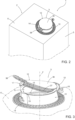
Figure 1 is a schematic perspective view of a package having an opening device according to the present invention, with parts removed for clarity; -
Figure 2 is an enlarged view of a portion of the package to which the opening device is coupled, with parts removed for clarity; -
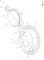
Figure 3 is an even further enlarged perspective view of a detail of the portion ofFigure 2 with the opening device being partially open, with parts removed for clarity; -
Figure 4 a perspective view of the detail ofFigure 3 with the opening device being open, with parts removed for clarity; and -
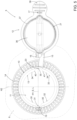
Figure 5 is a top view of the detail ofFigures 3 and4 , with parts removed for clarity. -
Number 1 indicates as a whole a package comprising: - a (sealed)
main body 2, preferentially amain body 2 formed from a multilayer packaging material; and - an
opening device 3 connected tomain body 2. - In more detail,
main body 2 may be filled with a pourable product, preferentially a pourable food product, such as milk, milk-drinks, yoghurt, yoghurt-drinks, wine, juice, beverages with pulp, tomato sauce, sugar, salt, etc. - More specifically,
main body 2 may have a designated pour opening (not shown and known as such) configured to allow for an outflow of the pourable product frommain body 2 andopening device 3 may be arranged and/or arrangeable about the designated pour opening and configured to allow for a controlled outpouring of the pourable product frommain body 2. - According to some preferred non-limiting embodiments,
main body 2 may be obtained from a packaging material, preferentially a composite packaging material, having a multilayer structure (not shown and known as such). - Preferentially, the packaging material may be provided in the form of a web and/or a sheet.
- Preferentially,
main body 2 may be obtained by forming a tube from the packaging material, longitudinally sealing the tube, filling the tube with the pourable product and by transversally sealing and cutting the tube. In some instances, the packaging material may be sterilized and/or cleaned prior to forming, longitudinally sealing, filling and transversally sealing and cutting the tube. - Preferentially, the packaging material may comprise at least one layer of fibrous material, such as e.g. paper or cardboard, and at least two layers of heat-seal plastic material, e.g. polyethylene, interposing the layer of fibrous material in between one another. One of these two layers of heat-seal plastic material may define an inner face of
main body 2 contacting the pourable product. - Preferably, the packaging material may also comprise a layer of gas- and light-barrier material, e.g. aluminum foil or ethylene vinyl alcohol (EVOH) film, in particular being arranged between one of the layers of the heat-seal plastic material and the layer of fibrous material. Preferentially, the packaging material may also comprise a further layer of heat-seal plastic material being interposed between the layer of gas- and light-barrier material and the layer of fibrous material.
- According to some non-limiting embodiments, opening device(s) 3 may be applied to the packaging material prior to arranging the packaging material within or during advancement of the packaging material through a packaging machine for forming, filling and sealing main body(ies) 2 from the packaging material carrying opening device(s) 3.
- Alternatively, opening device(s) 3 may be applied to the packaging material during the formation of main body (ies) 2 from the packaging material.
- Preferentially, application of opening device(s) 3 to the packaging material may occur by means of a molding process and/or adhesive bonding and/or ultrasonic sealing. Preferentially, opening device(s) 3 may be molded to the packaging material.
- With particular reference to
Figure 1 ,main body 2 may extend along a longitudinal axis A, a first transversal axis B perpendicular to longitudinal axis A and a second transversal axis C perpendicular to longitudinal axis A and to first transversal axis B. Preferentially, the size ofpackage 2 along longitudinal axis A may be larger than the size ofpackage 2 along first transversal axis B and second transversal axis C. - Preferentially,
main body 2 may be parallelepiped-shaped. - According to some preferred non-limiting embodiments,
main body 2 comprises afirst wall portion 4, preferentially transversal, more preferentially perpendicular, to longitudinal axis A, from whichmain body 2 extends along longitudinal axis A. Preferentially,first wall portion 4 may define a support surface ofpackage 1, in particular ofmain body 2, which is designed to be put in contact with a support, such as e.g. a shelf, when, in use, being e.g. exposed within a sales point or when being stored. In particular, when being arranged on a supportfirst wall portion 4 defines a bottom wall portion. - Preferentially,
main body 2 may also comprise aside wall 5 being (fixedly) connected tofirst wall portion 4, which may extend fromfirst wall portion 4, preferentially along longitudinal axis A. - Preferentially,
main body 2 may also comprise asecond wall portion 6 opposite tofirst wall portion 4 and being (fixedly) connected toside wall 5. - More specifically,
side wall 5 may be interposed betweenfirst wall portion 4 andsecond wall portion 6. - In particular, when
main body 2 is arranged on a supportsecond wall portion 6 defines a top wall portion. - According to the non-limiting embodiment shown,
second wall portion 6 may be inclined with respect tofirst wall portion 4 and/or longitudinal axis A. For example,second wall portion 6 may define a slanted top. - According to a non-limiting alternative embodiment not shown,
first wall portion 4 andsecond wall portion 6 may be parallel to one another. - According to some non-limiting embodiments,
second wall portion 6 carriesopening device 3, preferentially becausesecond wall portion 6 may comprise the designated pour opening. - With particular reference to
Figures 1 to 5 ,opening device 3 comprises at least: - a
collar 10 having apouring outlet 11 configured to allow for a (controlled) outflow of the pourable product from collar 10 (and/ormain body 2 and/or package 1); and - a
lid 12 coupled to collar 10 and configured to selectively close and open pouringoutlet 11. - In more detail,
lid 12 may be controllable between at least a closed position (seeFigures 1 and2 ) in whichlid 12 is configured to close pouringoutlet 11, in particular for impeding an outflow of the pourable product through pouringoutlet 11, and an open position (seeFigures 4 and5 ) in whichlid 12 is configured to open pouring outlet 11 (i.e. lid 12 is detached from pouring outlet 11), in particular for allowing an outflow of the pourable product through pouringoutlet 11. - In further detail,
collar 10 comprises a rim 13 (seeFigures 3 to 5 ) delimiting pouringoutlet 11. - Furthermore,
lid 12 is rupturably fixed tocollar 10, preferentially rim 13, in particular prior to a first-time control oflid 12 from the closed position to the open position. In particular, whenlid 12 is rupturably fixed tocollar 10,lid 12 is connected tocollar 10, e.g. by means of a rupturable coupling membrane. Advantageously,collar 10,lid 12 and the rupturable coupling membrane may be made as a single piece. Further advantageously,collar 10,lid 12 and the rupturable coupling membrane may be obtained by molding plastic material. -
Figure 3 shows a step during the first-time control oflid 12 from the closed position to the open position. - In more detail,
lid 12 may comprise aninteraction portion 21 rupturably fixed torim 13, preferentially by means of the coupling membrane. - Advantageously, a shape of
interaction portion 21 and/or of the coupling membrane may be (substantially) the same as a shape ofrim 13. - According to some preferred non-limiting embodiments,
lid 12 may be rupturably fixed in an irreversible manner tocollar 10, inparticular rim 13. After the first-time control oflid 12 from the closed position to the open position, it is again possible to controllid 12 in the closed position and to establish contact betweenlid 12 andcollar 11, preferentially rim 13, butlid 12 is not connected tocollar 10 anymore. - More specifically, the coupling membrane may be configured to (irreversibly) rupture during the first-time control of
lid 12 from the closed position to the open position. - It should be noted that
package 1 is immediately after its formation in an initial configuration in whichlid 12 is in the closed position.Package 1 is distributed and/or sold to a consumer while being in the initial configuration. - Thus, the first-time control of
lid 12 from the closed position to the open position is executed by the user. - With particular reference to
Figures 1 to 5 ,opening device 3 may also comprise abase frame 14 coupled and/or couplable tomain body 2, in particular tosecond wall portion 6. In particular,collar 10 extends frombase frame 14. - Advantageously,
opening device 3 may also comprise: - a tethering element 15 (permanently) tethering and/or
coupling lid 12 tocollar 10 and/orbase frame 14, in the specific case shown tocollar 10; and - preferentially also a retaining
element 16 configured to interact withtethering element 15 and/orlid 12 for retaining, preferentially for temporarily retaining,lid 12 in the open position. - Advantageously,
opening device 3 may also comprise a tamper-evidence element 17 configured to indicate to a user thatlid 12 has been controlled at least once from the closed position to the open position. In more detail, tamper-evidence element 17 may be connected tolid 12 andcollar 10 and/orbase frame 14, in the specific case shown tolid 12 andcollar 10. Additionally, upon the first-time control oflid 12 from the closed position to the open position, tamper-evidence element 17 ruptures. In the specific case shown, tamper-evidence element 17 may comprise aweaking section 18 configured to rupture and dividing tamper-evidence element 17 into two portions. According to some other solutions, weakingsection 18 may be attached tocollar 10 and/orbase frame 14 or tolid 12. - In more detail, rim 13 comprises a
first end portion 19 and asecond end portion 20 opposite tofirst portion 19.First end portion 19 may define a front portion ofrim 13 andsecond end portion 20 may define a back portion ofrim 13. - Additionally, during at least the first-time control of
lid 12 form the closed position to the open position,lid 12 is configured to detach fromfirst end portion 19 towardssecond end portion 20. In other words, during at least the first-time control oflid 12 form the closed position to the open position,lid 12 detaches at the beginning fromfirst end portion 19 and at the end fromsecond end portion 20. - Additionally, during at least the first-time control of
lid 12 form the closed position to the open position,lid 12 is configured to move along an opening axis E, preferentially opening axis E extending fromfirst end portion 19 tosecond end portion 20. - With particular reference to
Figures 3 and4 ,collar 10 may comprise a center axis F. Preferentially,collar 10 may extend, preferentially frombase frame 14, along center axis F. - Preferentially, pouring
outlet 11 and rim 13 may be arranged at a first axial end ofcollar 10 with respect to center axis F. - According to some preferred non-limiting embodiments,
collar 10 may delimit (and/or comprises) aflow channel 22 for the pourable product. - According to some preferred non-limiting embodiments,
collar 10 and/orrim 13 may be mirror symmetric with respect to a symmetry plane H1 comprising center axis F. - According to the example embodiment shown, symmetry plane H1 may comprise opening axis E.
- In one embodiment not shown,
collar 10 and/orrim 13 may be mirror symmetric with respect to a further symmetry plane comprising center axis F and being perpendicular to symmetry plane H1. - With particular reference to
Figures 4 and5 ,second end portion 20 comprises aradial protrusion 30. In one embodiment,radial protrusion 30 is a notch and/or an indentation/ and or a slot obtained inrim 13 and extending away from center axis F. In particular, the Applicant has observed thatradial protrusion 30 allows to reduce a detachment force, i.e. the force needed to finally and completelyseparate lid 12 andcollar 11 from each other, compared to the case of an end portion having a circular shape. A reduction of the detachment force corresponds e.g. to a reduction of the deformation ofcollar 11 and/or a reduction of the possibility of a product splash. - Additionally,
first end portion 19 may comprise an auxiliaryradial protrusion 31. In one embodiment, auxiliaryradial protrusion 31 is a notch and/or an indentation/ and or a slot obtained inrim 13 and extending away from center axis F. In particular, auxiliaryradial protrusion 31 allows to reduce an opening force, i.e. the force needed to initiallyseparate lid 12 andcollar 11 from each other. - Preferentially,
radial protrusion 30 and auxiliaryradial protrusion 31 may extend along opposite directions with respect to opening axis E. - Preferentially, during at least the first-time control of
lid 12 from the closed position to the open position,lid 12 detaches at the beginning fromfirst end portion 19, preferentially auxiliaryradial protrusion 31, and at the end fromsecond end portion 20, preferentiallyradial protrusion 30. - According to some preferred non-limiting embodiments,
radial protrusion 30 may be curved. Preferentially, also auxiliaryradial protrusion 31 may be curved. - In the example shown,
radial protrusion 30 and auxiliaryradial protrusion 31 may have a (slightly) different shape. - In another example not shown,
radial protrusion 30 and auxiliaryradial protrusion 31 may have the same shape. - According to some preferred non-limiting embodiments, an imaginary line L connecting
radial protrusion 30 and auxiliaryradial protrusion 31 with one another intersects center axis F and/or may be parallel to opening axis E. - In addition or alternatively, an angular difference between a first radial position of
radial protrusion 30 with respect to center axis F and a second radial position of auxiliaryradial protrusion 31 with respect to center axis F may (substantially) equal 180°. - According to some preferred non-limiting embodiments, tethering
element 15 may be connected to a portion ofcollar 10 carryingsecond end portion 20, preferentiallyradial protrusion 30. - With particular reference to
Figures 4 and5 ,rim 13 may comprise afirst half section 32 comprisingfirst end portion 19 and asecond half section 33 comprisingsecond end portion 20. - Preferentially,
first half section 32 andsecond half section 33 may be divided by a further plane H2, preferentially further plane H2 being perpendicular to symmetry plane H1 and comprising center axis F. - With particular reference to
Figures 4 and5 ,radial protrusion 30 may extend between afirst connection portion 40 and asecond connection portion 41 ofrim 13, preferentially of second half-section 33. - Preferentially,
first connection portion 40 andsecond connection portion 41 may define points in which rim 13 has a change in its profile, particularly in its curvature with respect to center axis F. - According to some preferred non-limiting embodiments,
radial protrusion 30 may be radially more distanced from center axis F than the other portions of second half section 33 (i.e. all the other portions ofsecond half section 33 not corresponding to radial protrusion 30). - In more detail, a first maximum radial distance of
radial protrusion 30 from center axis F may be larger than a first auxiliary radial distance of the other portions ofsecond half section 33 from center axis F. - In particular, the first maximum radial distance is to be construed in view of the zone of
radial protrusion 30 that is the radially more distanced from center axis F and considering an inner face ofradial protrusion 30 facing center axis F. - In a similar manner, the first auxiliary radial distance of the other portions of
second half section 33 from center axis F is determined considering a respective inner face ofsecond half section 33 being different fromradial protrusion 30. - According to some preferred non-limiting embodiments, a second maximum radial distance of auxiliary
radial protrusion 30 from center axis F may be larger than a second auxiliary radial distance of the other portions offirst half section 32 from center axis F. - In this context, the terms second maximum radial distance and second auxiliary radial distance can be construed in an analogous manner as one can construe the terms first maximum radial distance and first auxiliary radial distance, in this case, with respect to auxiliary
radial protrusion 31 and the portions offirst half section 32 being different from auxiliaryradial protrusion 31. - According to some preferred non-limiting embodiments,
radial protrusion 30 may be interposed between twoauxiliary sections 34 ofrim 13, preferentially ofsecond half section 33. - According to some possible non-limiting embodiments,
first connection portion 40 may connect oneauxiliary section 34 toradial protrusion 30 andsecond connection portion 41 may connect the otherauxiliary section 34 toradial protrusion 30. - Preferentially,
first connection portion 40 andsecond connection portion 41 may be convex (in particular, when considering the shape offirst connection portion 40 andsecond connection portion 41 from center axis F andauxiliary portions 34 andradial protrusion 30 may be concave (in particular, when considering the shape ofauxiliary portions 34 andradial protrusion 30 from center axis F. - According to some possible non-limiting embodiments,
radial protrusion 30 may define a first curvature. Preferentially,radial protrusion 30 may be described (at least approximated) by an arc-shaped section of a first circle and the first curvature may be defined as a respective first radius of the first circle. - Moreover,
auxiliary sections 34 may define respective second curvatures. In one embodiment, the respective second curvatures may equal one another. Eachauxiliary section 34 may be described by an arc-shaped section of a respective second circle and each second curvature may be defined as the respective second radius of the second circle. - Additionally, the first curvature may be different from each one of the second curvatures.
- Preferentially, the first radius may be different from, more preferentially smaller than, each one of the second radii.
- According to some preferred non-limiting embodiments, auxiliary
radial protrusion 31 may be interposed between twoauxiliary sections 35 ofrim 13, preferentially offirst half section 32. - Preferentially, auxiliary
radial protrusion 31 may define a third curvature. Auxiliaryradial protrusion 31 may be described (at least approximated) by an arc-shaped section of a third circle and the third curvature may be defined as the respective third radius of the respective third circle. - Moreover,
auxiliary sections 35 may define respective fourth curvatures. In one embodiment, the respective fourth curvatures may equal one another. Eachauxiliary section 35 may be described (at least approximated) by an arc-shaped section of a respective fourth circle and each fourth curvature may be defined as the respective fourth radius of the respective fourth circle. - Additionally, the third curvature is different from each one of the fourth curvatures.
- Preferentially, the third radius may be different, more preferentially smaller, than each one of the fourth radii.
- According to the non-limiting embodiment shown, first radius and third radius may be (slightly) different from one another.
- In one preferred embodiment, third radius is smaller than first radius.
- According to a non-shown non-limiting embodiment, first radius and third radius may equal one another.
- With particular reference to
Figures 1 to 5 ,lid 12 may comprise at least acover portion 36 configured to cover pouringoutlet 11 withlid 12 being arranged in the closed position. - Preferentially,
cover portion 36 may be (substantially) planar. - Moreover,
lid 12 may comprise anannular protrusion 37 protruding fromlid 12, preferentially coverportion 36, and intoflow channel 22 withlid 12 being in the closed position. Preferentially,annular protrusion 37 may compriseinteraction portion 21. - Preferentially,
annular protrusion 37 may have a shape (substantially) equal to the shape ofrim 13. - Preferentially,
lid 12 may also comprises agripping element 38 protruding, in particular laterally protruding, fromcover portion 36, and preferentially being configured to allow the consumer to grip grippingelement 38 so that the consumer can controllid 12 between the closed position and the open position. More preferentially, grippingelement 38 may comprise ribs improving the gripping properties of grippingelement 38. - In use, the outpouring of the pourable product from
package 1 requires controllinglid 12 from the closed position to the open position so as to open the pouring outlet. - The first-
time lid 12 is controlled from the closed position to the open position,lid 12 is detached fromrim 13. Thereby,radial protrusion 30 allows a decrease of the detachment force compared to known opening devices. - When
lid 12 is newly positioned in the closed position,lid 12 is in contact withrim 13, but is not connected torim 13 anymore. - The advantages of
opening device 3 and/or ofpackage 1 according to the present invention will be clear from the foregoing description. - In particular,
radial protrusion 30 allows to decrease the detachment force, i.e. the force that is needed to detachlid 12 fromrim 13 atradial protrusion 30. This allows e.g. to reduce the deformation ofcollar 11. - Clearly, changes may be made to opening
device 3 and/orpackage 1 as described herein without, however, departing from the scope of protection as defined in the accompanying claims.
Claims (15)
- Opening device (3) for a package (1) filled with a pourable product;the opening device (3) comprises at least:- a collar (10) having a pouring outlet (11); and- a lid (12) configured to selectively close and open the pouring outlet (11) and being controllable between at least a closed position in which the lid (12) is configured to close the pouring outlet (11) and an open position in which the lid (12) is configured to open the pouring outlet (11) ;wherein the collar (10) comprises a rim (13) delimiting the pouring outlet (11);wherein the lid (12) is rupturably fixed to the rim (13) by means of a coupling membrane;wherein during a first-time control of the lid (12) from the closed position to the open position, the lid (12) detaches from the rim (13) and the coupling membrane is configured to be ruptured;wherein the rim (13) comprises a first end portion (19) and a second end portion (20) opposite to the first end portion (19);wherein during at least the first-time control of the lid (12) from the closed position to the open position, the lid (12) detaches at the beginning from the first end portion (19) and at the end from the second end portion (20);wherein the second end portion (20) comprises a radial protrusion (30).
- Opening device according to claim 1, wherein the radial protrusion (30) is a notch and/or an indentation/ and or a slot obtained in the rim (13) and extending away from a center axis (F) of the collar (10).
- Opening device according to claim 1 or 2, wherein the radial protrusion (30) is curved.
- Opening device according to any one of the preceding claims, wherein the radial protrusion (30) is interposed between two auxiliary sections (34) of the rim (13);wherein the radial protrusion (30) defines a first curvature and the auxiliary sections (34) define respective second curvatures;wherein the first curvature is different from each one of the second curvatures.
- Opening device according to claim 4, wherein the first curvature defines a first radius and the respective second curvatures define respective second radii;
wherein the first radius is smaller than each one of the second radii. - Opening device according to any one of the preceding claims, wherein the collar (10) comprises a center axis (F);wherein the rim (13) comprises a first half section (32) comprising the first end portion (19) and a second half section (33) comprising the second end portion (20);wherein a first maximum radial distance of the radial protrusion (30) from the center axis (F) is larger than an auxiliary radial distance of the other portions of the second half section (33) from the center axis (F).
- Opening device according to any one of the preceding claims, and further comprising a tethering element (15) tethering the lid (12) to a portion of the collar (10) comprising the second end portion (20).
- Opening device according to claim 7, and further comprising a retaining element (16) configured to interact with the tethering element (15) and/or the lid (12) for retaining the lid (12) in the open position.
- Opening device according to any one of the preceding claims, wherein the first end portion (19) comprises an auxiliary radial protrusion (31) opposite to the radial protrusion (30).
- Opening device according to claim 9, wherein an imaginary line (L) connecting the radial protrusion (30) and the auxiliary radial protrusion (31) with one another intersects the center axis (F); and/orwherein an angular difference between the radial protrusion (30) and the auxiliary radial protrusion (31) substantially equals 180°; and/orwherein during at least the first-time control of the lid (12) from the closed position to the open position, the lid (12) moves along an opening axis (E), the opening axis (E) being parallel to an imaginary line (L) connecting the radial protrusion (30) and the auxiliary radial protrusion (31) with one another; and/orwherein the auxiliary radial protrusion (31) is a notch and/or an indentation/ and or a slot obtained in the rim (13) and extending away from a center axis (F) of the collar (10) .
- Opening device according to any one of the preceding claims, wherein the rim (13) is mirror symmetric with respect to a symmetry plane (H1) comprising the center axis (F).
- Opening device according to any one of the preceding claims, wherein the lid (12) comprises an interaction portion (21) rupturably fixed to the rim (13) by the coupling membrane;
wherein a shape of the interaction portion (21) substantially equals a shape of the rim (13). - Package (1) comprising a main body (2) filled with a pourable product and an opening device (3) according to any one of the preceding claims applied to the main body (2) .
- Package (1) according to claim 13, wherein the main body (2) is formed from a multilayer packaging material.
- Package according to claim 13 or 14, wherein the opening device (3) is molded to the main body (2).
Applications Claiming Priority (1)
| Application Number | Priority Date | Filing Date | Title |
|---|---|---|---|
| IT102023000013506A IT202300013506A1 (en) | 2023-06-29 | 2023-06-29 | OPENING DEVICE FOR A PACKAGE AND PACKAGE HAVING AN OPENING DEVICE |
Publications (1)
| Publication Number | Publication Date |
|---|---|
| EP4484318A1 true EP4484318A1 (en) | 2025-01-01 |
Family
ID=87889531
Family Applications (1)
| Application Number | Title | Priority Date | Filing Date |
|---|---|---|---|
| EP24182317.8A Pending EP4484318A1 (en) | 2023-06-29 | 2024-06-14 | Opening device for a package and package having an opening device |
Country Status (6)
| Country | Link |
|---|---|
| EP (1) | EP4484318A1 (en) |
| CN (1) | CN121241009A (en) |
| AU (1) | AU2024310800A1 (en) |
| IT (1) | IT202300013506A1 (en) |
| MX (1) | MX2025011979A (en) |
| WO (1) | WO2025002856A1 (en) |
Citations (6)
| Publication number | Priority date | Publication date | Assignee | Title |
|---|---|---|---|---|
| JPS63102660U (en) * | 1986-12-22 | 1988-07-04 | ||
| EP1279609B1 (en) * | 2001-07-27 | 2006-02-01 | Tetra Laval Holdings & Finance SA | Opening device for package for pourable food products, and package including the same |
| JP6190589B2 (en) * | 2012-12-27 | 2017-08-30 | 株式会社吉野工業所 | Refill container |
| JP6458349B2 (en) * | 2014-03-31 | 2019-01-30 | 凸版印刷株式会社 | Outlet stopper and packaging container |
| EP4001150A1 (en) | 2020-11-16 | 2022-05-25 | Tetra Laval Holdings & Finance S.A. | Lid-spout assembly for a package and package having a lid-spout assembly |
| US20230182972A1 (en) * | 2020-05-27 | 2023-06-15 | Tetra Laval Holdings & Finance S.A. | Lid-spout assembly for a package and package having a lid-spout assembly |
-
2023
- 2023-06-29 IT IT102023000013506A patent/IT202300013506A1/en unknown
-
2024
- 2024-06-14 EP EP24182317.8A patent/EP4484318A1/en active Pending
- 2024-06-14 WO PCT/EP2024/066625 patent/WO2025002856A1/en not_active Ceased
- 2024-06-14 CN CN202480037032.0A patent/CN121241009A/en active Pending
- 2024-06-14 AU AU2024310800A patent/AU2024310800A1/en active Pending
-
2025
- 2025-10-07 MX MX2025011979A patent/MX2025011979A/en unknown
Patent Citations (6)
| Publication number | Priority date | Publication date | Assignee | Title |
|---|---|---|---|---|
| JPS63102660U (en) * | 1986-12-22 | 1988-07-04 | ||
| EP1279609B1 (en) * | 2001-07-27 | 2006-02-01 | Tetra Laval Holdings & Finance SA | Opening device for package for pourable food products, and package including the same |
| JP6190589B2 (en) * | 2012-12-27 | 2017-08-30 | 株式会社吉野工業所 | Refill container |
| JP6458349B2 (en) * | 2014-03-31 | 2019-01-30 | 凸版印刷株式会社 | Outlet stopper and packaging container |
| US20230182972A1 (en) * | 2020-05-27 | 2023-06-15 | Tetra Laval Holdings & Finance S.A. | Lid-spout assembly for a package and package having a lid-spout assembly |
| EP4001150A1 (en) | 2020-11-16 | 2022-05-25 | Tetra Laval Holdings & Finance S.A. | Lid-spout assembly for a package and package having a lid-spout assembly |
Also Published As
| Publication number | Publication date |
|---|---|
| MX2025011979A (en) | 2025-11-03 |
| WO2025002856A1 (en) | 2025-01-02 |
| CN121241009A (en) | 2025-12-30 |
| AU2024310800A1 (en) | 2025-10-09 |
| IT202300013506A1 (en) | 2024-12-29 |
Similar Documents
| Publication | Publication Date | Title |
|---|---|---|
| EP3919404B1 (en) | Lid-spout assembly for a package, package having a lid-spout assembly and method for molding a lid-spout assembly | |
| EP3892563A1 (en) | Spout for a package, lid-spout assembly for a package and package having a spout | |
| EP3892564B1 (en) | Lid-spout assembly for a package | |
| EP3892559B1 (en) | Lid-spout assembly for a package and package therewith | |
| EP3915893B1 (en) | Lid-spout assembly for a package and package having a lid-spout assembly | |
| EP4159631B1 (en) | Opening device for a package, mold for molding an opening device for a package and package having an opening device | |
| US12515853B2 (en) | Lid-spout assembly for a package and package having a lid-spout assembly | |
| US12473123B2 (en) | Lid-spout assembly for a package and package having a lid-spout assembly | |
| EP4159634B1 (en) | Opening device for a package, mold for molding an opening device for a package and package having an opening device | |
| EP4159402B1 (en) | Opening device for a package, mold for molding an opening device for a package and package having an opening device | |
| EP4159633A1 (en) | Opening device for a package, mold for molding an opening device for a package and package having an opening device | |
| EP4177181B1 (en) | Opening device for a package and package having an opening device | |
| WO2025002856A1 (en) | Opening device for a package and package having an opening device | |
| EP4480842A2 (en) | Opening device for a package, mold for molding an opening device and package having an opening device | |
| EP4079652B1 (en) | Opening device for a package and package having an opening device | |
| EP4159632A1 (en) | Opening device for a package, mold for molding an opening device for a package and package having an opening device | |
| EP4001149A1 (en) | Opening device for a package and package having an opening device |
Legal Events
| Date | Code | Title | Description |
|---|---|---|---|
| PUAI | Public reference made under article 153(3) epc to a published international application that has entered the european phase |
Free format text: ORIGINAL CODE: 0009012 |
|
| STAA | Information on the status of an ep patent application or granted ep patent |
Free format text: STATUS: THE APPLICATION HAS BEEN PUBLISHED |
|
| AK | Designated contracting states |
Kind code of ref document: A1 Designated state(s): AL AT BE BG CH CY CZ DE DK EE ES FI FR GB GR HR HU IE IS IT LI LT LU LV MC ME MK MT NL NO PL PT RO RS SE SI SK SM TR |
|
| STAA | Information on the status of an ep patent application or granted ep patent |
Free format text: STATUS: REQUEST FOR EXAMINATION WAS MADE |
|
| 17P | Request for examination filed |
Effective date: 20250701 |