EP4484184A1 - Cooling device for electrically driven vehicle - Google Patents
Cooling device for electrically driven vehicle Download PDFInfo
- Publication number
- EP4484184A1 EP4484184A1 EP24180486.3A EP24180486A EP4484184A1 EP 4484184 A1 EP4484184 A1 EP 4484184A1 EP 24180486 A EP24180486 A EP 24180486A EP 4484184 A1 EP4484184 A1 EP 4484184A1
- Authority
- EP
- European Patent Office
- Prior art keywords
- rotational speed
- compressor
- fan
- corrected
- cooling
- Prior art date
- Legal status (The legal status is an assumption and is not a legal conclusion. Google has not performed a legal analysis and makes no representation as to the accuracy of the status listed.)
- Pending
Links
Images





Classifications
-
- B—PERFORMING OPERATIONS; TRANSPORTING
- B60—VEHICLES IN GENERAL
- B60H—ARRANGEMENTS OF HEATING, COOLING, VENTILATING OR OTHER AIR-TREATING DEVICES SPECIALLY ADAPTED FOR PASSENGER OR GOODS SPACES OF VEHICLES
- B60H1/00—Heating, cooling or ventilating devices
- B60H1/32—Cooling devices
- B60H1/3204—Cooling devices using compression
- B60H1/3205—Control means therefor
-
- B—PERFORMING OPERATIONS; TRANSPORTING
- B60—VEHICLES IN GENERAL
- B60H—ARRANGEMENTS OF HEATING, COOLING, VENTILATING OR OTHER AIR-TREATING DEVICES SPECIALLY ADAPTED FOR PASSENGER OR GOODS SPACES OF VEHICLES
- B60H1/00—Heating, cooling or ventilating devices
- B60H1/00271—HVAC devices specially adapted for particular vehicle parts or components and being connected to the vehicle HVAC unit
-
- B—PERFORMING OPERATIONS; TRANSPORTING
- B60—VEHICLES IN GENERAL
- B60H—ARRANGEMENTS OF HEATING, COOLING, VENTILATING OR OTHER AIR-TREATING DEVICES SPECIALLY ADAPTED FOR PASSENGER OR GOODS SPACES OF VEHICLES
- B60H1/00—Heating, cooling or ventilating devices
- B60H1/00271—HVAC devices specially adapted for particular vehicle parts or components and being connected to the vehicle HVAC unit
- B60H1/00278—HVAC devices specially adapted for particular vehicle parts or components and being connected to the vehicle HVAC unit for the battery
-
- B—PERFORMING OPERATIONS; TRANSPORTING
- B60—VEHICLES IN GENERAL
- B60H—ARRANGEMENTS OF HEATING, COOLING, VENTILATING OR OTHER AIR-TREATING DEVICES SPECIALLY ADAPTED FOR PASSENGER OR GOODS SPACES OF VEHICLES
- B60H1/00—Heating, cooling or ventilating devices
- B60H1/00357—Air-conditioning arrangements specially adapted for particular vehicles
- B60H1/00385—Air-conditioning arrangements specially adapted for particular vehicles for vehicles having an electrical drive, e.g. hybrid or fuel cell
-
- B—PERFORMING OPERATIONS; TRANSPORTING
- B60—VEHICLES IN GENERAL
- B60H—ARRANGEMENTS OF HEATING, COOLING, VENTILATING OR OTHER AIR-TREATING DEVICES SPECIALLY ADAPTED FOR PASSENGER OR GOODS SPACES OF VEHICLES
- B60H1/00—Heating, cooling or ventilating devices
- B60H1/00507—Details, e.g. mounting arrangements, desaeration devices
-
- B—PERFORMING OPERATIONS; TRANSPORTING
- B60—VEHICLES IN GENERAL
- B60H—ARRANGEMENTS OF HEATING, COOLING, VENTILATING OR OTHER AIR-TREATING DEVICES SPECIALLY ADAPTED FOR PASSENGER OR GOODS SPACES OF VEHICLES
- B60H1/00—Heating, cooling or ventilating devices
- B60H1/00642—Control systems or circuits; Control members or indication devices for heating, cooling or ventilating devices
-
- B—PERFORMING OPERATIONS; TRANSPORTING
- B60—VEHICLES IN GENERAL
- B60K—ARRANGEMENT OR MOUNTING OF PROPULSION UNITS OR OF TRANSMISSIONS IN VEHICLES; ARRANGEMENT OR MOUNTING OF PLURAL DIVERSE PRIME-MOVERS IN VEHICLES; AUXILIARY DRIVES FOR VEHICLES; INSTRUMENTATION OR DASHBOARDS FOR VEHICLES; ARRANGEMENTS IN CONNECTION WITH COOLING, AIR INTAKE, GAS EXHAUST OR FUEL SUPPLY OF PROPULSION UNITS IN VEHICLES
- B60K1/00—Arrangement or mounting of electrical propulsion units
-
- B—PERFORMING OPERATIONS; TRANSPORTING
- B60—VEHICLES IN GENERAL
- B60H—ARRANGEMENTS OF HEATING, COOLING, VENTILATING OR OTHER AIR-TREATING DEVICES SPECIALLY ADAPTED FOR PASSENGER OR GOODS SPACES OF VEHICLES
- B60H1/00—Heating, cooling or ventilating devices
- B60H1/00642—Control systems or circuits; Control members or indication devices for heating, cooling or ventilating devices
- B60H1/00814—Control systems or circuits characterised by their output, for controlling particular components of the heating, cooling or ventilating installation
- B60H1/00821—Control systems or circuits characterised by their output, for controlling particular components of the heating, cooling or ventilating installation the components being ventilating, air admitting or air distributing devices
- B60H1/00828—Ventilators, e.g. speed control
-
- B—PERFORMING OPERATIONS; TRANSPORTING
- B60—VEHICLES IN GENERAL
- B60H—ARRANGEMENTS OF HEATING, COOLING, VENTILATING OR OTHER AIR-TREATING DEVICES SPECIALLY ADAPTED FOR PASSENGER OR GOODS SPACES OF VEHICLES
- B60H1/00—Heating, cooling or ventilating devices
- B60H1/00271—HVAC devices specially adapted for particular vehicle parts or components and being connected to the vehicle HVAC unit
- B60H2001/00307—Component temperature regulation using a liquid flow
-
- B—PERFORMING OPERATIONS; TRANSPORTING
- B60—VEHICLES IN GENERAL
- B60H—ARRANGEMENTS OF HEATING, COOLING, VENTILATING OR OTHER AIR-TREATING DEVICES SPECIALLY ADAPTED FOR PASSENGER OR GOODS SPACES OF VEHICLES
- B60H1/00—Heating, cooling or ventilating devices
- B60H1/00507—Details, e.g. mounting arrangements, desaeration devices
- B60H2001/006—Noise reduction
-
- B—PERFORMING OPERATIONS; TRANSPORTING
- B60—VEHICLES IN GENERAL
- B60H—ARRANGEMENTS OF HEATING, COOLING, VENTILATING OR OTHER AIR-TREATING DEVICES SPECIALLY ADAPTED FOR PASSENGER OR GOODS SPACES OF VEHICLES
- B60H1/00—Heating, cooling or ventilating devices
- B60H1/32—Cooling devices
- B60H2001/3236—Cooling devices information from a variable is obtained
- B60H2001/3248—Cooling devices information from a variable is obtained related to pressure
- B60H2001/325—Cooling devices information from a variable is obtained related to pressure of the refrigerant at a compressing unit
-
- B—PERFORMING OPERATIONS; TRANSPORTING
- B60—VEHICLES IN GENERAL
- B60H—ARRANGEMENTS OF HEATING, COOLING, VENTILATING OR OTHER AIR-TREATING DEVICES SPECIALLY ADAPTED FOR PASSENGER OR GOODS SPACES OF VEHICLES
- B60H1/00—Heating, cooling or ventilating devices
- B60H1/32—Cooling devices
- B60H2001/3236—Cooling devices information from a variable is obtained
- B60H2001/3255—Cooling devices information from a variable is obtained related to temperature
-
- B—PERFORMING OPERATIONS; TRANSPORTING
- B60—VEHICLES IN GENERAL
- B60H—ARRANGEMENTS OF HEATING, COOLING, VENTILATING OR OTHER AIR-TREATING DEVICES SPECIALLY ADAPTED FOR PASSENGER OR GOODS SPACES OF VEHICLES
- B60H1/00—Heating, cooling or ventilating devices
- B60H1/32—Cooling devices
- B60H2001/3236—Cooling devices information from a variable is obtained
- B60H2001/3255—Cooling devices information from a variable is obtained related to temperature
- B60H2001/3258—Cooling devices information from a variable is obtained related to temperature of the air at a condensing unit
-
- B—PERFORMING OPERATIONS; TRANSPORTING
- B60—VEHICLES IN GENERAL
- B60H—ARRANGEMENTS OF HEATING, COOLING, VENTILATING OR OTHER AIR-TREATING DEVICES SPECIALLY ADAPTED FOR PASSENGER OR GOODS SPACES OF VEHICLES
- B60H1/00—Heating, cooling or ventilating devices
- B60H1/32—Cooling devices
- B60H2001/3236—Cooling devices information from a variable is obtained
- B60H2001/3266—Cooling devices information from a variable is obtained related to the operation of the vehicle
-
- B—PERFORMING OPERATIONS; TRANSPORTING
- B60—VEHICLES IN GENERAL
- B60H—ARRANGEMENTS OF HEATING, COOLING, VENTILATING OR OTHER AIR-TREATING DEVICES SPECIALLY ADAPTED FOR PASSENGER OR GOODS SPACES OF VEHICLES
- B60H1/00—Heating, cooling or ventilating devices
- B60H1/32—Cooling devices
- B60H2001/3269—Cooling devices output of a control signal
- B60H2001/327—Cooling devices output of a control signal related to a compressing unit
- B60H2001/3272—Cooling devices output of a control signal related to a compressing unit to control the revolving speed of a compressor
-
- B—PERFORMING OPERATIONS; TRANSPORTING
- B60—VEHICLES IN GENERAL
- B60H—ARRANGEMENTS OF HEATING, COOLING, VENTILATING OR OTHER AIR-TREATING DEVICES SPECIALLY ADAPTED FOR PASSENGER OR GOODS SPACES OF VEHICLES
- B60H1/00—Heating, cooling or ventilating devices
- B60H1/32—Cooling devices
- B60H2001/3269—Cooling devices output of a control signal
- B60H2001/3276—Cooling devices output of a control signal related to a condensing unit
- B60H2001/3277—Cooling devices output of a control signal related to a condensing unit to control the air flow
-
- B—PERFORMING OPERATIONS; TRANSPORTING
- B60—VEHICLES IN GENERAL
- B60K—ARRANGEMENT OR MOUNTING OF PROPULSION UNITS OR OF TRANSMISSIONS IN VEHICLES; ARRANGEMENT OR MOUNTING OF PLURAL DIVERSE PRIME-MOVERS IN VEHICLES; AUXILIARY DRIVES FOR VEHICLES; INSTRUMENTATION OR DASHBOARDS FOR VEHICLES; ARRANGEMENTS IN CONNECTION WITH COOLING, AIR INTAKE, GAS EXHAUST OR FUEL SUPPLY OF PROPULSION UNITS IN VEHICLES
- B60K11/00—Arrangement in connection with cooling of propulsion units
- B60K11/02—Arrangement in connection with cooling of propulsion units with liquid cooling
-
- B—PERFORMING OPERATIONS; TRANSPORTING
- B60—VEHICLES IN GENERAL
- B60L—PROPULSION OF ELECTRICALLY-PROPELLED VEHICLES; SUPPLYING ELECTRIC POWER FOR AUXILIARY EQUIPMENT OF ELECTRICALLY-PROPELLED VEHICLES; ELECTRODYNAMIC BRAKE SYSTEMS FOR VEHICLES IN GENERAL; MAGNETIC SUSPENSION OR LEVITATION FOR VEHICLES; MONITORING OPERATING VARIABLES OF ELECTRICALLY-PROPELLED VEHICLES; ELECTRIC SAFETY DEVICES FOR ELECTRICALLY-PROPELLED VEHICLES
- B60L58/00—Methods or circuit arrangements for monitoring or controlling batteries or fuel cells, specially adapted for electric vehicles
- B60L58/10—Methods or circuit arrangements for monitoring or controlling batteries or fuel cells, specially adapted for electric vehicles for monitoring or controlling batteries
- B60L58/24—Methods or circuit arrangements for monitoring or controlling batteries or fuel cells, specially adapted for electric vehicles for monitoring or controlling batteries for controlling the temperature of batteries
- B60L58/26—Methods or circuit arrangements for monitoring or controlling batteries or fuel cells, specially adapted for electric vehicles for monitoring or controlling batteries for controlling the temperature of batteries by cooling
Definitions
- the present invention belongs to a technical field relating to a cooling device for an electrically driven vehicle.
- Patent Literature 1 discloses a cooling fan control device where a coolant pressure reference fan rotational speed is set based on a current coolant pressure of an air conditioner, an upper limit guard rotational speed of a fan corresponding to the required air outlet temperature is set, and in the case where a vehicle is currently in a stopped state, where a current engine speed is an idle rotational speed, and where the coolant pressure reference fan rotational speed is larger than the upper limit guard rotational speed, the upper limit guard rotational speed is set as a fan rotational speed, and the coolant pressure reference fan rotational speed is set as the fan rotational speed in other cases.
- Patent Literature 1 Japanese Patent Laid-Open No. 10-196364
- a higher rotational speed of a compressor or a higher rotational speed of a fan causes a larger noise.
- a higher rotational speed of the compressor and a higher rotational speed of the fan are set for a higher required cooling capability.
- Examples of the scene where a cooling device is required to have high cooling capability include a scene where a battery is quickly charged during a period in which a vehicle is in a stopped state and a scene of high load traveling, such as uphill traveling and towing traveling. Accordingly, large noise is generated in such scenes.
- the vehicle is an electrically driven vehicle that travels by using a drive motor as a main drive source
- engine sound is not generated and hence, there is a concern that noise generated from the cooling device causes annoyance not only to people around the vehicle, but also to the occupant of the vehicle even during traveling.
- the present invention has been made in view of such a point, and it is an object to suppress noise during cooling while a decrease in cooling capability is suppressed as much as possible.
- a first mode as disclosed herein is directed to a cooling device for an electrically driven vehicle, the cooling device cooling, by utilizing a coolant, an electric drive part mounted on a vehicle, the cooling device being characterized by including: a compressor that compresses the coolant; a fan that draws outside air into a condensing device that condenses, by cooling, the coolant compressed by the compressor; an electric drive part temperature detector that detects a temperature of the electric drive part; a coolant pressure detector that detects a pressure of the coolant compressed by the compressor; and a controller that controls the compressor and the fan, in which the controller calculates required cooling capability at least based on a detected result from the electric drive part temperature detector, the controller calculates a set compressor rotational speed, which is a rotational speed of the compressor based on the required cooling capability, the controller calculates a set fan rotational speed, which is a rotational speed of the fan based on a detected result from
- the rotational speed of the fan is set based on the pressure of coolant, a higher rotational speed of the fan is set for a higher rotational speed of the compressor. Therefore, noise tends to become higher than the noise regulation value when high cooling capability is necessary in normal control.
- the rotational speed of the fan is set not based on the pressure of coolant, but based on the rotational speed of the compressor. Particularly, a lower rotational speed of the fan is set for a higher rotational speed of the compressor. In other words, the rotational speed of the fan may be set lower as the rotational speed of the compressor becomes higher.
- a higher rotational speed of the compressor or a higher rotational speed of the fan causes a higher cooling capability. Therefore, by setting one of the rotational speed of the compressor and the rotational speed of the fan to a high rotational speed and by setting the other to a low rotational speed, it is possible to suppress a decrease in cooling capability. Consequently, a combination of the corrected compressor rotational speed and the corrected fan rotational speed can be set to a combination that can suppress a decrease in cooling capability as much as possible within a range where noise is or takes the noise regulation value or less. As a result, noise is suppressed during cooling while a decrease in cooling capability is suppressed as much as possible.
- the cooling device further includes an outside air temperature detector that detects a temperature of the outside air, and the controller sets the corrected compressor rotational speed and the corrected fan rotational speed by further taking into account the temperature of the outside air.
- the temperature of outside air corresponds to the temperature of air drawn by the fan and hence, by taking into account the temperature of outside air, it is possible to set a more appropriate corrected fan rotational speed that can suppress a decrease in cooling capability as much as possible. Consequently, it is possible to suppress noise during cooling while a decrease in cooling capability is suppressed more effectively.
- the controller sets the corrected compressor rotational speed and the corrected fan rotational speed such that the generated noise is or takes the noise regulation value.
- the controller obtains cooling capabilities and sets a combination, among the plurality of combinations, having cooling capability closest to the required cooling capability for the corrected compressor rotational speed and the corrected fan rotational speed.
- an appropriate corrected compressor rotational speed and an appropriate corrected fan rotational speed can be set within a range where noise can be suppressed. Consequently, it is possible to suppress noise during cooling while a decrease in cooling capability is suppressed more effectively.
- the controller sets a combination, among the plurality of combinations, having a lowest rotational speed of the compressor for the corrected compressor rotational speed and the corrected fan rotational speed.
- the controller calculates a first compressor rotational speed candidate and a first fan rotational speed candidate, the first compressor rotational speed candidate being higher than the compressor rotational speed limit by a fixed rotational speed, the first fan rotational speed candidate being based on the first compressor rotational speed candidate, the controller calculates a second compressor rotational speed candidate and a second fan rotational speed candidate, the second compressor rotational speed candidate being lower than the compressor rotational speed limit by a fixed rotational speed, the second fan rotational speed candidate being based on the second compressor rotational speed candidate, and for a combination of the compressor rotational speed limit and the fan rotational speed limit, a combination of the first compressor rotational speed candidate and the first fan rotational speed candidate, and a combination of the second compressor rotational speed candidate and the second fan rotational speed candidate, the controller obtains cooling capabilities and the controller sets a combination, among the combinations, having cooling capability closest to the required cooling capability for the corrected compressor rotational speed and the corrected fan rotational speed.
- the cooling device for an electrically driven vehicle it is possible to suppress noise during cooling while a decrease in cooling capability is suppressed as much as possible.
- FIG. 1 shows a vehicle 100 including a cooling device 1 according to an embodiment 1.
- the vehicle 100 is an electrically driven vehicle that can travel mainly by a motor or a drive motor 102 that is rotated by power.
- the vehicle 100 is a vehicle, such as an electric automobile or a hybrid automobile, for example.
- the vehicle 100 includes the drive motor 102.
- the rotation of the drive motor 102 is transferred to one or more wheels, particularly two wheels of four wheels 101 via a shaft, the two wheels being located on the front side or the rear side.
- This transmission causes the vehicle 100 to move (travel).
- the drive motor 102 may be a motor generator, and serves as a power generator during deceleration (regeneration) of the vehicle 100.
- the drive motor 102 may be connected to a battery module 70 via an inverter 103 and a converter 104.
- the battery module 70 may be formed by stacking a plurality of battery cells having a rectangular box shape (not shown in the drawing).
- the battery module 70 may be disposed below the floor panel of the vehicle 100.
- the battery cell may be a lithium ion battery or a nickel-hydrogen battery, for example.
- the inverter 103 converts DC power into AC power.
- the inverter 103 may convert DC power, supplied via the converter 104, into AC current or AC power with three different phases, and supplies the AC current or AC power to the drive motor 102.
- the inverter 103 converts AC power, generated by the drive motor 102, into DC power, and supplies the DC power to the converter 104.
- the converter 104 lowers DC power (or the voltage of DC power, outputted from the battery module 70, to a driving voltage of the drive motor 102, and supplies the power to the inverter 103.
- the converter 104 raises DC power (or the voltage of DC power), supplied from the inverter 103, and charges the battery module 70 with the power.
- the drive motor 102, the inverter 103, the converter 104, and the battery module 70 are examples of electric drive parts mounted on the vehicle 100.
- FIG. 2 shows the cooling device 1 mounted on the vehicle 100.
- the cooling device 1 can cool the electric drive parts.
- the cooling device 1 can directly cool, for example, the battery module 70 by an endothermic reaction that occurs at the time of a phase change from liquid coolant to gas coolant.
- the cooling device 1 can indirectly cool the drive motor 102 by coolant via a cooling water cooling mechanism 21, which will be described later.
- the coolant is, for example, HFO (hydrofluoroolefin) coolant, and is specifically R1234yf.
- the cooling device 1 may include a heat exchanger 2 for battery, and includes a compressor 3 and a condenser 4, the heat exchanger 2 causing coolant and the battery module 70 to exchange heat, the compressor 3 compressing the coolant that flows out from the heat exchanger 2 for battery, the condenser 4 condensing, by cooling, the coolant compressed by the compressor 3.
- the cooling device 1 may have a main inflow path 11, a first branch inflow path 11a, and a second branch inflow path 11b, the main inflow path 11 being a coolant path directing toward the heat exchanger 2 for battery from the condenser 4, the first branch inflow path 11a being branched from the main inflow path 11 and directing toward the cooling water cooling mechanism 21, the second branch inflow path 11b being branched from the main inflow path 11 and directing toward the air conditioner 22.
- the cooling device 1 may have a main outflow path 12, a first branch outflow path 12a, and a second branch outflow path 12b, the main outflow path 12 being a coolant path directing toward the compressor 3 from the heat exchanger 2 for battery, the first branch outflow path 12a directing toward the main outflow path 12 from the cooling water cooling mechanism 21, the second branch outflow path 12b directing toward the main outflow path 12 from the air conditioner 22.
- the cooling device 1 may also include an expansion valve 5 provided in the main inflow path 11 to reduce the pressure of coolant condensed by the condenser 4.
- the compressor 3 compresses the coolant subjected to heat exchange with the battery module 70.
- the compressor 3 may be, for example, a scroll compressor, and can adjust the pressure of coolant that flows out from the compressor 3 by adjusting rotational speed.
- a higher compressor rotational speed causes a higher pressure of coolant that is caused to flow out from the compressor 3.
- a higher compressor rotational speed causes a larger amount of coolant that is caused to flow out from the compressor 3.
- the condenser 4 may be disposed at the front portion of the vehicle 100.
- a fan 41 is provided particularly behind the condenser 4 on the vehicle.
- the condenser 4 may cool coolant by traveling air or by a combination of traveling air and air drawn by the rotation of the fan 41.
- the condenser 4 cools coolant by air drawn by the rotation of the fan 41.
- the pressure of coolant is not reduced, but the temperature of the coolant is reduced, so that the coolant is condensed and liquified.
- the fan 41 may be a motor-driven fan.
- the fan 41 may include a small-sized electric motor (not shown in the drawing), and rotates by the rotation of the electric motor. A higher rotational speed of the fan 41 causes the fan 41 to draw a larger amount of air.
- the air volume of the fan 41 is directly proportional to the rotational speed of the fan.
- a receiver tank 42 may be provided downstream of the condenser 4.
- the receiver tank 42 temporarily stores coolant liquefied by the condenser 4.
- the receiver tank 42 may be connected to the main inflow path 11. When coolant liquefied by the condenser 4 flows into the receiver tank 42, coolant flows out from the receiver tank 42 to the main inflow path 11 by an amount corresponding to the amount of the coolant that flows into the receiver tank 42.
- the expansion valve 5 reduces the pressure of coolant in the main inflow path 11, and causes the coolant to flow into the heat exchanger 2 for battery.
- the temperature of the coolant that passes through the expansion valve 5 may be reduced due to adiabatic expansion. Further, due to a reduction in pressure caused by the expansion valve 5, the saturation temperature (corresponding to the boiling point) may be reduced.
- a reduction in pressure of coolant caused by the expansion valve 5 slows the flow of coolant in the heat exchanger 2 and hence, the coolant in the heat exchanger 2 evenly exchanges heat with the battery module 70.
- the expansion valve 5 may also be utilized for adjusting the flow rate of coolant that is caused to flow into the heat exchanger 2 for battery. To be more specific, while a larger opening of the expansion valve 5 causes a higher flow rate of coolant that flows into the heat exchanger 2 for battery, a smaller opening of the expansion valve 5 causes a lower flow rate of coolant that flows into the heat exchanger 2 for battery.
- the cooling water cooling mechanism 21 may include an expansion valve and a heat exchanger.
- the expansion valve is provided in the first branch inflow path 11a.
- the air conditioner 22 includes an expansion valve, a heat exchanger, and a fan.
- the expansion valve is provided in the second branch inflow path 11b.
- the rotational speed of the fan is set based on a target temperature in a vehicle cabin.
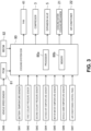
- the vehicle 100 may include a cooling system ECM (Electric Control Module) 80 being a controller that mainly performs control of the cooling device 1.
- the cooling system ECM 80 may include one or more processors 80a and a memory 80b, each of the one or more processors 80a including a CPU, the memory 80b including a ROM and a RAM, and storing various programs.
- the memory 80b may be a nonvolatile memory, for example.
- the programs relating to control performed by the cooling system ECM 80 are stored in the memory 80b.
- the cooling system ECM 80 is performed by the processor 80a reading the program stored in the memory 80b.
- the cooling system ECM 80 receives input(s) of signal(s) from a battery temperature sensor SW1 and/or a motor water temperature sensor SW5, receives input of signal from a second coolant pressure sensor SW3, and may receive inputs of signals from a first coolant pressure sensor SW2, an outside air temperature sensor SW4, a vehicle cabin temperature sensor SW6, and/or an air conditioning control panel SW7, the battery temperature sensor SW1 detecting the temperature of the battery cell, the first coolant pressure sensor SW2 detecting the pressure of coolant that flows into the compressor 3, the second coolant pressure sensor SW3 detecting the pressure of coolant before flowing into the condenser 4, the coolant being compressed by the compressor 3, the outside air temperature sensor SW4 detecting the temperature of outside air, the motor water temperature sensor SW5 detecting the water temperature of cooling water for the drive motor 102, the vehicle cabin temperature sensor SW6 detecting a temperature in the vehicle cabin, the air conditioning control panel SW7 controlling air conditioning in the vehicle cabin.
- the cooling system ECM 80 may also receive inputs of signals from a PCM (Powertrain Control Module) 81 and a BECM (Battery Energy Control Module) 82, the PCM 81 being a controller that performs control of the entire power system of the vehicle 100, the BECM 82 being a controller that performs control of charging and discharging of the battery module 70.
- PCM Powertrain Control Module
- BECM Battery Energy Control Module
- a signal from a vehicle speed sensor SW8 may be inputted to the PCM 81.
- each of the PCM 81 and the BECM 82 may include a processor and a memory.
- the battery temperature sensor SW1 may be disposed on the battery module 70 at a position in the vicinity of an outflow port for coolant, for example.
- the first coolant pressure sensor SW2 may be disposed in the main outflow path 12 at a position upstream of the compressor 3.
- the second coolant pressure sensor SW3 may be disposed at a position downstream of the compressor 3 and upstream of the condenser 4.
- the outside air temperature sensor SW4 may be disposed on the front side of the condenser 4 on the vehicle.
- the temperature of outside air detected by the outside air temperature sensor SW4 corresponds to the temperature of air drawn by the fan 41.
- the motor water temperature sensor SW5 may face the cooling water passage of the drive motor 102.
- the water temperature detected by the motor water temperature sensor SW5 may be assumed as the temperature of the drive motor 102.
- the air conditioning control panel SW7 may be a panel manipulated by an occupant of the vehicle 100, and is provided with a switch that controls ON and OFF of air conditioning, a switch that sets the air volume of air, a switch that sets a target temperature in the vehicle cabin, and other switches.
- a plurality of battery temperature sensors SW1 may be provided.
- another battery temperature sensor SW1 may be provided at the center of the battery module 70 as viewed in a plan view in addition to the battery temperature sensor SW1 provided to the battery module 70 at a position in the vicinity of the outflow port for coolant.
- the battery temperature sensor SW1 and the motor water temperature sensor SW5 are examples of electric drive part temperature detectors.
- the cooling system ECM 80 controls the fan 41 and the compressor 3, and may control the expansion valve 5, the cooling water cooling mechanism 21, and the air conditioner 22, based on signals from the respective sensors SW1 to SW7, a signal from the PCM 81, and a signal from the BECM 82.
- the cooling system ECM 80 obtains information relating to vehicle speed from the PCM 81, obtains information relating to target temperatures of cooling targets (the drive motor 102 and the battery module 70) from the BECM 82, and obtains information relating to a target temperature in the vehicle cabin from the air conditioning control panel SW7.
- the cooling system ECM 80 compares detected results from the battery temperature sensor SW1, the motor water temperature sensor SW5, and the vehicle cabin temperature sensor SW6 with the respective target temperatures to calculate a required cooling capability Qr of the cooling device 1.
- the cooling system ECM 80 sets a compressor rotational speed based on the required cooling capability Qr.
- the cooling system ECM 80 calculates the air volume to be supplied to the condenser 4 based on the detected result from the second coolant pressure sensor SW3, and sets a fan rotational speed based on the air volume.
- the cooling system ECM 80 causes each of the compressor 3 and the fan 41 to rotate at the rotational speed set for each of the compressor 3 and the fan 41, and adjusts the opening of the expansion valve 5, the opening of the expansion valve of the cooling water cooling mechanism 21, and the opening of the expansion valve of the air conditioner 22 in such a way as to allow coolant to flow into each valve at a necessary flow rate.
- the cooling system ECM 80 also adjusts the rotational speed of the fan of the air conditioner 22 according to the target temperature in the vehicle cabin. Cooling capability may be, for example, heat capacity at which coolant can absorb heat per unit time.
- the cooling system ECM 80 may also calculate the air volume of traveling air based on the information relating to the vehicle speed obtained from the PCM 81. In setting a fan rotational speed, the cooling system ECM 80 may take the air volume of traveling air into account.
- the cooling system ECM 80 sets a fan rotational speed such that an air volume, being the deficit obtained by subtracting an air volume obtained from traveling air from the air volume to be supplied to the condenser 4, can be obtained by the fan 41.
- the cooling system ECM 80 may set the fan rotational speed to zero, causing the fan 41 not to rotate.
- the condenser 4 cools coolant by utilizing at least one of traveling air and air drawn by the fan 41. That is, the condenser 4 cools coolant by utilizing outside air. Therefore, cooling capability of the cooling device 1 depends on the temperature of outside air.
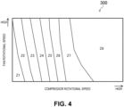
- FIG. 4 and FIG. 5 show cooling capability maps of the cooling device 1.
- FIG. 4 is a low temperature cooling capability map 300 for which the temperature of outside air is relatively low
- FIG. 5 is a high temperature cooling capability map 400 for which the temperature of outside air is relatively high.
- the low temperature and high temperature cooling capability maps 300, 400 may be stored in the memory 80b. Although only two cooling capability maps are exemplified in this embodiment, in practice, three or more cooling capability maps are stored in the memory 80b for temperatures of outside air.
- Regions Z1 to Z8 are regions having similar cooling capabilities.
- the region Z1 has the lowest cooling capability
- the region Z8 has the highest cooling capability
- the regions Z2 to Z7 have higher cooling capability as the regions come closer to the region Z8.
- Boundary lines between the respective regions Z1 to Z8 are lines at which cooling capability is equal. Basically, a higher compressor rotational speed and a higher fan rotational speed cause a larger cooling capability and hence, in each of the regions Z1 to Z8, cooling capability increases as a position goes away from the boundary line on the lower side toward the upper right side.
- the region Z8 has a larger area in the low temperature cooling capability map 300 than the high temperature cooling capability map 400.
- Examples of a scene where the cooling device 1 is required to have high cooling capability include a scene where the battery module 70 is quickly charged during a period in which the vehicle 100 is in a stopped state and a scene of high load traveling, such as uphill traveling and towing traveling. Accordingly, large noise may be generated in such scenes.
- the vehicle 100 in the case where the vehicle 100 is an electrically driven vehicle that can travel by using the drive motor 102 as a main drive source, engine sound is not generated and hence, there may be a concern that noise generated from the cooling device 1 causes annoyance not only to people around the vehicle 100, but also to the occupant of the vehicle 100 even during traveling.
- a compressor rotational speed limit NCL and a fan rotational speed limit NFL are set in advance based on predetermined noise regulation values and, when at least one of a set compressor rotational speed and a set fan rotational speed that are a compressor rotational speed and a fan rotational speed set based on the required cooling capability, is larger than the compressor rotational speed limit NCL or the fan rotational speed limit NFL, the compressor 3 and the fan 41 are respectively actuated at the compressor rotational speed limit NCL and the fan rotational speed limit NFL.
- actuation point P0 a combination of the set compressor rotational speed and the set fan rotational speed
- actuation point limit PL a combination of the compressor rotational speed limit NCL and the fan rotational speed limit NFL
- the actuation point is moved from the region Z7 to the region Z6, so that cooling capability decreases.
- a decrease in cooling capability may reduce charging efficiency of the battery module 70, may promote deterioration of the drive motor 102, and may reduce cooling efficiency of air conditioning in the vehicle cabin.
- an actuation point is calculated at which a noise level indicating magnitude of noise is equal to or less than the noise level at the actuation point limit PL (that is, noise regulation value), and a decrease in cooling capability can be suppressed.
- the cooling system ECM 80 performs noise suppression control where a corrected compressor rotational speed (or a compressor rotational speed) is set and a corrected fan rotational speed (or a fan rotational speed) is set based on the corrected compressor rotational speed such that a noise level becomes equal to or less than the noise regulation value.
- a lower corrected fan rotational speed is set for a higher corrected compressor rotational speed.
- the fan rotational speed is set basically based on the detected result from the second coolant pressure sensor SW3.
- a higher compressor rotational speed causes a higher detected result (pressure of coolant) and hence, basically, a higher fan rotational speed is set for a higher compressor rotational speed. That is, in normal control, as shown by a broken line in the drawing on the upper side in FIG. 6 , combinations of the compressor rotational speed and the fan rotational speed are set within a range extending from the lower left portion to the upper right portion of the cooling capability map.
- FIG. 4 , FIG. 5 , and the drawing on the upper side in FIG. 6 in practice, combinations that bring about substantially the same cooling capability are also present outside the range of the normal control. Therefore, by setting the fan rotational speed without depending on the pressure of coolant, it is possible to set an actuation point at which high cooling capability can be maintained and noise level can be suppressed.
- the cooling system ECM 80 calculates or obtains cooling capabilities that are exhibited when the compressor 3 and the fan 41 are actuated at respective actuation point candidates.
- the cooling system ECM 80 may select, as a corrected actuation point, an actuation point candidate having cooling capability closest to the required cooling capability, and may set the compressor rotational speed and the fan rotational speed at the selected corrected actuation point as the corrected compressor rotational speed and the corrected fan rotational speed, respectively.
- An actuation point candidate and cooling capability at each actuation point candidate may be obtained by calculation by the cooling system ECM 80, or may be obtained in such a manner that an actuation point candidate and cooling capability at each actuation point candidate are stored in advance in the memory 80b for each cooling capability map in the form of a map 500, which will be described later, and the cooling system ECM 80 may read an appropriate map based on the temperature of outside air.
- cooling capability closest to the required cooling capability may include the case where cooling capability is equal to the required cooling capability.
- actuation point candidate having cooling capability equal to the required cooling capability
- such an actuation point candidate is the actuation point candidate having cooling capability closest to the required cooling capability.
- noise regulation line SL a downward-sloping straight line expressing that a higher compressor rotational speed causes a lower fan rotational speed.
- This noise regulation line SL may be obtained by setting fan rotational speed based on compressor rotational speed such that not the pressure of coolant but a noise level takes the noise regulation value.
- the upper limit value of the compressor rotational speed may be set based on the upper limit pressure of the operation of the compressor 3, and the lower limit value of the compressor rotational speed may be set based on the rotational speed at which an abnormal operation, such as choking, does not occur.
- the noise regulation line SL may be set based on the noise regulation value. For example, when the noise regulation value is 20 decibels, the noise regulation line on which a noise level is 20 decibels is set. This noise regulation value can be arbitrarily set.
- the drawing on the lower side in FIG. 6 is the map 500 showing cooling capability on the noise regulation line SL.
- position of actuation point is shown on the horizontal axis
- cooling capability is shown on the vertical axis.
- an actuation point having a lower compressor rotational speed and a higher fan rotational speed is closer to the left side
- an actuation point having a higher compressor rotational speed and a lower fan rotational speed is closer to the right side.
- the actuation point limit PL, an actuation point candidate P1, and an actuation point candidate P2 respectively correspond to PL, P1, and P2 in the drawing on the upper side in FIG. 6 .
- cooling capability may become equal to the required cooling capability (Qr in the drawing on the lower side in FIG. 6 ) at the actuation point candidate P1.
- cooling capability may become the maximum cooling capability (Qm in the drawing on the lower side in FIG. 6 ) at the actuation point candidate P2.
- the cooling system ECM 80 may set such an actuation point candidate as a corrected actuation point.
- the cooling system ECM 80 may set the actuation point candidate P1 as a corrected actuation point, and may set the compressor rotational speed and the fan rotational speed at the actuation point candidate P1 as a corrected compressor rotational speed and a corrected fan rotational speed, respectively. This is because that although cooling capability at the actuation point candidate P2 is higher than that at the actuation point candidate P1, when an actuation point having cooling capability equal to or more than the required cooling capability is selected, there is a possibility of a reduction in cooling efficiency.
- the cooling system ECM 80 may set, as a corrected actuation point, the actuation point candidate having cooling capability closest to the required cooling capability, that is, an actuation point candidate having the maximum cooling capability (the actuation point candidate P2 in this case).
- the cooling system ECM 80 may select, as a corrected actuation point, an actuation point candidate having a lower compressor rotational speed. This is because, from the viewpoint of cooling efficiency, as low a compressor rotational speed as possible and as high a fan rotational speed as possible allow a higher cooling efficiency.
- FIG. 7 is a flowchart showing a processing operation of the cooling system ECM 80 particularly in performing noise suppression control. This flowchart may be performed for every predetermined number of cycles.
- the cooling system ECM 80 may receive and read signals from various sensors SW1 to SW7, the PCM 81, and the BECM 82.
- step S102 the cooling system ECM 80 may calculate required cooling capability.
- the cooling system ECM 80 may calculate a set compressor rotational speed NC based on the required cooling capability.
- step S104 the cooling system ECM 80 may calculate a set fan rotational speed NF based on the detected result from the second coolant pressure sensor SW3.
- the cooling system ECM 80 may determine whether a vehicle speed is less than a predetermined vehicle speed. In the case where a vehicle speed is high, a large road noise is generated and hence, even when noise of magnitude equal to or more than the noise regulation value is generated from the cooling device 1, the occupant of the vehicle 100 is less likely to feel annoyance. Therefore, when the vehicle speed is high, the cooling system ECM 80 does not perform noise suppression control.
- the cooling system ECM 80 may advance to step S106.
- the cooling system ECM 80 may advance to step S111.
- the predetermined vehicle speed is a speed at which road noise of magnitude equal to or more than the noise regulation value is generated, and the predetermined vehicle speed may be set to 20 km/h, for example.
- step S106 the cooling system ECM 80 determines whether the set compressor rotational speed NC is larger than the compressor rotational speed limit NCL.
- the cooling system ECM 80 may advance to step S108.
- the cooling system ECM 80 may advance to step S107.
- the cooling system ECM 80 may determine whether the set fan rotational speed NF is larger than the fan rotational speed limit NFL. When the determination is that the set fan rotational speed NF is larger than the fan rotational speed limit NFL, that is, YES, the cooling system ECM 80 may advance to step S108. In contrast, when the determination is that the set fan rotational speed NF is equal to or less than the fan rotational speed limit NFL, that is, NO, the cooling system ECM 80 may advance to step S111.
- the cooling system ECM 80 may calculate or obtain cooling capabilities at respective actuation point candidates on the noise regulation line SL.
- the cooling system ECM 80 may set, as a corrected actuation point, the actuation point candidate having cooling capability closest to the required cooling capability, and may set the compressor rotational speed and the fan rotational speed at the corrected actuation point as a corrected compressor rotational speed and a corrected fan rotational speed.
- the cooling system ECM 80 may set this actuation point candidate as a corrected actuation point.
- the cooling system ECM 80 may set, as a corrected actuation point, an actuation point candidate having the lowest compressor rotational speed.
- step S110 the cooling system ECM 80 may actuate the cooling device 1 at the corrected compressor rotational speed and the corrected fan rotational speed.
- the process may return after step S110.
- the cooling system ECM 80 may actuate the cooling device 1 at the set compressor rotational speed and the set fan rotational speed. The process returns after step S111.
- the cooling device includes the compressor 3 that compresses a coolant, the fan 41 that draws outside air into the condenser 4 that condenses, by cooling, the coolant compressed by the compressor 3, the battery temperature sensor SW 1 that detects the temperature of the battery module 70, the motor water temperature sensor SW5 that detects the temperature of the drive motor 102, the second coolant pressure sensor SW3 that detects the pressure of the coolant compressed by the compressor 3, and the cooling system ECM 80 that controls the compressor 3 and the fan 41, wherein the cooling system ECM 80 calculates the required cooling capability at least based on the detected results from the battery temperature sensor SW1 and the motor water temperature sensor SW5, the cooling system ECM 80 calculates the set compressor rotational speed, which is the rotational speed of the compressor 3 based on the required cooling capability, the cooling system ECM 80 calculates the set fan rotational speed, which is the rotational speed of the fan 41 based on the detected result from the second coolant pressure sensor SW3, when both of the first condition that the set compressor rotational speed is equal to or
- the cooling device may further include the outside air temperature sensor SW4 that detects the temperature of outside air, and the cooling system ECM 80 may set the corrected compressor rotational speed and the corrected fan rotational speed by further taking into account the temperature of outside air.
- the temperature of air drawn by the fan can be taken into account and hence, it is possible to set a more appropriate corrected fan rotational speed that can suppress a decrease in cooling capability as much as possible. Accordingly, it is possible to suppress a decrease in cooling capability more effectively.
- the cooling system ECM 80 may set the corrected compressor rotational speed and the corrected fan rotational speed such that the generated noise takes the noise regulation value.
- the corrected compressor rotational speed and the corrected fan rotational speed can be set to as high values as possible. Therefore, it is possible to suppress a decrease in cooling capability more effectively.
- the cooling system ECM 80 may calculate or obtain cooling capabilities, and the cooling system ECM 80 sets a combination having cooling capability closest to the required cooling capability for the corrected compressor rotational speed and the corrected fan rotational speed.
- the cooling system ECM 80 may set a combination having the lowest compressor rotational speed for the corrected compressor rotational speed and the corrected fan rotational speed. With such a configuration, it is possible to set the compressor rotational speed to as low a value as possible. A lower compressor rotational speed requires a smaller amount of coolant to be cooled and hence, it is possible to efficiently cool the coolant. Therefore, it is possible to enhance cooling efficiency.
- FIG. 8 schematically shows a method for calculating a corrected actuation point for a cooling device according to the embodiment 2.
- the cooling system ECM 80 may calculate a first compressor rotational speed candidate, a first fan rotational speed candidate, a second compressor rotational speed candidate, and a second fan rotational speed candidate, the first compressor rotational speed candidate being higher than the compressor rotational speed limit NCL by a fixed rotational speed, the first fan rotational speed candidate being based on the first compressor rotational speed candidate, the second compressor rotational speed candidate being lower than the compressor rotational speed limit NCL by the fixed rotational speed, the second fan rotational speed candidate being based on the second compressor rotational speed candidate.
- the cooling system ECM 80 may calculate or obtain cooling capabilities that are exhibited when the compressor 3 and the fan 41 are actuated at the respective actuation points.
- the cooling system ECM 80 may select, as a corrected actuation point, the actuation point having cooling capability closest to the required cooling capability, and may set the compressor rotational speed and the fan rotational speed at the corrected actuation point as a corrected compressor rotational speed and a corrected fan rotational speed, respectively. That is, the actuation point limit PL is also one of actuation point candidates.
- the cooling system ECM 80 may calculate the first actuation point candidate P4 and the second actuation point candidate P5 from the noise regulation line SL. That is, the first fan rotational speed candidate is lower than the fan rotational speed limit NFL, and the second fan rotational speed candidate is higher than the fan rotational speed limit NFL.
- the absolute value of the difference between the first compressor rotational speed candidate and the compressor rotational speed limit NCL and the absolute value of the difference between the second compressor rotational speed candidate and the compressor rotational speed limit NCL may be the same fixed value and hence, the absolute value of the difference between the first fan rotational speed candidate and the fan rotational speed limit NFL may be equal to the absolute value of the difference between the second fan rotational speed candidate and the fan rotational speed limit NFL.
- the fixed value may be set in advance.
- cooling capability at the first actuation point candidate P4 is closest to the required cooling capability and hence, the first actuation point candidate P4 may be selected as a corrected actuation point.
- the cooling system ECM 80 may select, as a corrected actuation point, an actuation point candidate having cooling capability higher than the required cooling capability.
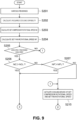
- FIG. 9 and FIG. 10 show a flowchart showing a processing operation of the cooling system ECM 80 in performing noise suppression control according to the embodiment 2. This flowchart is performed for every predetermined number of cycles.
- the cooling system ECM 80 may receive and read signals from various sensors SW1 to SW7, the PCM 81, and the BECM 82.
- step S202 the cooling system ECM 80 may calculate required cooling capability.
- the cooling system ECM 80 may calculate a set compressor rotational speed NC based on the required cooling capability.
- the cooling system ECM 80 may calculate a set fan rotational speed NF based on the detected result from the second coolant pressure sensor SW3.
- the cooling system ECM 80 may determine whether a vehicle speed is less than a predetermined vehicle speed. When the determination is that the vehicle speed is less than the predetermined vehicle speed, that is, YES, the cooling system ECM 80 advances to step S206. In contrast, when the determination is that the vehicle speed is equal to or more than the predetermined vehicle speed, that is, NO, the cooling system ECM 80 advances to step S215.
- step S206 the cooling system ECM 80 may determine whether the set compressor rotational speed NC is larger than the compressor rotational speed limit NCL. When the determination is that the set compressor rotational speed NC is larger than the compressor rotational speed limit NCL, that is, YES, the cooling system ECM 80 may advance to step S208. In contrast, when the determination is that the set compressor rotational speed NC is equal to or less than the compressor rotational speed limit NCL, that is, NO, the cooling system ECM 80 may advance to step S207.
- the cooling system ECM 80 may determine whether the set fan rotational speed NF is larger than the fan rotational speed limit NFL. When the determination is that the set fan rotational speed NF is larger than the fan rotational speed limit NFL, that is, YES, the cooling system ECM 80 may advance to step S208. In contrast, when the determination is that the set fan rotational speed NF is equal to or less than the fan rotational speed limit NFL, that is, NO, the cooling system ECM 80 may advance to step S215.
- the cooling system ECM 80 may calculate a first compressor rotational speed candidate.
- the cooling system ECM 80 may calculate a first fan rotational speed candidate based on the first compressor rotational speed candidate.
- step S210 the cooling system ECM 80 may calculate a second compressor rotational speed candidate.
- the cooling system ECM 80 may calculate a second fan rotational speed candidate based on the second compressor rotational speed candidate.
- the cooling system ECM 80 may calculate cooling capabilities at the actuation point limit PL, the first actuation point candidate P4, and the second actuation point candidate P5.
- the cooling system ECM 80 may set an actuation point closest to the required cooling capability as a corrected actuation point, and may set the compressor rotational speed and the fan rotational speed at this actuation point as a corrected compressor rotational speed and a corrected fan rotational speed.
- step S214 the cooling system ECM 80 may actuate the cooling device 1 at the corrected compressor rotational speed and the corrected fan rotational speed. The process returns after step S214.
- the cooling system ECM 80 may actuate the cooling device 1 at the set compressor rotational speed and the set fan rotational speed. The process returns after step S215.
- the fan rotational speed is set based on the compressor rotational speed and hence, it is possible to suppress noise while a decrease in cooling capability is suppressed as much as possible. It is also possible to reduce the amount of arithmetic operation of the cooling system ECM 80 as much as possible. Consequently, it is possible to reduce power consumption as much as possible.
- the above-described embodiments 1 and 2 adopt the configuration in which the corrected actuation points are set on the noise regulation line SL.
- corrected actuation points need not be set on the noise regulation line SL and may be set within a region below the noise regulation line SL in the cooling capability map.
- the set compressor rotational speed and the set fan rotational speed are respectively set as the compressor rotational speed and the fan rotational speed.
- the compressor rotational speed limit NCL and the fan rotational speed limit NFL may be respectively temporarily set as the compressor rotational speed and the fan rotational speed.
- the cooling device 1 cools the battery module 70 by causing coolant to flow through the heat exchanger 2.
- the cooling device 1 may further include a heat exchanger (chiller), in the heat exchanger 2, for causing cooling water subjected to heat exchange with coolant to flow through the heat exchanger.
- the present invention can be effectively used as a cooling device for an electrically driven vehicle, the cooling device cooling, by utilizing coolant, electric drive parts mounted on a vehicle.
Landscapes
- Engineering & Computer Science (AREA)
- Mechanical Engineering (AREA)
- Physics & Mathematics (AREA)
- Thermal Sciences (AREA)
- Transportation (AREA)
- Chemical & Material Sciences (AREA)
- Combustion & Propulsion (AREA)
- Sustainable Development (AREA)
- Sustainable Energy (AREA)
- Life Sciences & Earth Sciences (AREA)
- Air-Conditioning For Vehicles (AREA)
- Cooling Or The Like Of Electrical Apparatus (AREA)
- Secondary Cells (AREA)
Abstract
When at least one of a first condition that a set compressor rotational speed is equal to or less than a compressor rotational speed limit set in advance based on a predetermined noise regulation value and a second condition that a set fan rotational speed is equal to or less than a fan rotational speed limit set in advance based on the predetermined noise regulation value is not satisfied, a cooling device 1 sets a corrected compressor rotational speed such that noise generated with actuation of a compressor 3 and a fan 41 takes the predetermined noise regulation value or less, and sets a corrected fan rotational speed based on the corrected compressor rotational speed. The cooling device 1 sets a lower value of the corrected fan rotational speed for a higher corrected compressor rotational speed.
Description
- The present invention belongs to a technical field relating to a cooling device for an electrically driven vehicle.
- Conventionally, for cooling devices mounted on vehicles, studies are conducted on measures to suppress noise generated in cooling the coolant.
-
Patent Literature 1, for example, discloses a cooling fan control device where a coolant pressure reference fan rotational speed is set based on a current coolant pressure of an air conditioner, an upper limit guard rotational speed of a fan corresponding to the required air outlet temperature is set, and in the case where a vehicle is currently in a stopped state, where a current engine speed is an idle rotational speed, and where the coolant pressure reference fan rotational speed is larger than the upper limit guard rotational speed, the upper limit guard rotational speed is set as a fan rotational speed, and the coolant pressure reference fan rotational speed is set as the fan rotational speed in other cases. - [Patent Literature 1]
Japanese Patent Laid-Open No. 10-196364 - A higher rotational speed of a compressor or a higher rotational speed of a fan causes a larger noise. Basically, a higher rotational speed of the compressor and a higher rotational speed of the fan are set for a higher required cooling capability. Examples of the scene where a cooling device is required to have high cooling capability include a scene where a battery is quickly charged during a period in which a vehicle is in a stopped state and a scene of high load traveling, such as uphill traveling and towing traveling. Accordingly, large noise is generated in such scenes. Particularly, in the case where the vehicle is an electrically driven vehicle that travels by using a drive motor as a main drive source, engine sound is not generated and hence, there is a concern that noise generated from the cooling device causes annoyance not only to people around the vehicle, but also to the occupant of the vehicle even during traveling.
- In the cooling fan control device described in
Patent Literature 1, it is expected that noise is suppressed by reducing the fan rotational speed to the upper limit guard rotational speed. However, a reduction in fan rotational speed causes a decrease in cooling capability. Therefore, there is room for improvement to achieve both high cooling capability and suppression of noise. - The present invention has been made in view of such a point, and it is an object to suppress noise during cooling while a decrease in cooling capability is suppressed as much as possible.
- The above-mentioned problem is solved by the present invention as defined in
claim 1. Particularly, a first mode as disclosed herein is directed to a cooling device for an electrically driven vehicle, the cooling device cooling, by utilizing a coolant, an electric drive part mounted on a vehicle, the cooling device being characterized by including: a compressor that compresses the coolant; a fan that draws outside air into a condensing device that condenses, by cooling, the coolant compressed by the compressor; an electric drive part temperature detector that detects a temperature of the electric drive part; a coolant pressure detector that detects a pressure of the coolant compressed by the compressor; and a controller that controls the compressor and the fan, in which the controller calculates required cooling capability at least based on a detected result from the electric drive part temperature detector, the controller calculates a set compressor rotational speed, which is a rotational speed of the compressor based on the required cooling capability, the controller calculates a set fan rotational speed, which is a rotational speed of the fan based on a detected result from the coolant pressure detector, when both of a first condition that the set compressor rotational speed is equal to or less than a compressor rotational speed limit set in advance based on a predetermined noise regulation value and a second condition that the set fan rotational speed is equal to or less than a fan rotational speed limit set in advance based on the predetermined noise regulation value are satisfied, the controller actuates the compressor and the fan at the set compressor rotational speed and the set fan rotational speed respectively, but when at least one of the first condition and the second condition is not satisfied, the controller sets a corrected compressor rotational speed such that noise generated with actuation of the compressor and the fan is or takes the predetermined noise regulation value or less, and the controller sets a corrected fan rotational speed based on the corrected compressor rotational speed, and actuates the compressor and the fan at the corrected compressor rotational speed and the corrected fan rotational speed respectively, and the controller sets a lower value of the corrected fan rotational speed for a higher corrected compressor rotational speed. The controller may set the corrected fan rotational speed lower as the corrected compressor rotational speed becomes higher. - That is, in the case where the rotational speed of the fan is set based on the pressure of coolant, a higher rotational speed of the fan is set for a higher rotational speed of the compressor. Therefore, noise tends to become higher than the noise regulation value when high cooling capability is necessary in normal control. In view of the above, when it is expected that noise may become higher than the noise regulation value, the rotational speed of the fan is set not based on the pressure of coolant, but based on the rotational speed of the compressor. Particularly, a lower rotational speed of the fan is set for a higher rotational speed of the compressor. In other words, the rotational speed of the fan may be set lower as the rotational speed of the compressor becomes higher.
- A higher rotational speed of the compressor or a higher rotational speed of the fan causes a higher cooling capability. Therefore, by setting one of the rotational speed of the compressor and the rotational speed of the fan to a high rotational speed and by setting the other to a low rotational speed, it is possible to suppress a decrease in cooling capability. Consequently, a combination of the corrected compressor rotational speed and the corrected fan rotational speed can be set to a combination that can suppress a decrease in cooling capability as much as possible within a range where noise is or takes the noise regulation value or less. As a result, noise is suppressed during cooling while a decrease in cooling capability is suppressed as much as possible.
- Particularly, in the second mode as disclosed herein, in the first mode, the cooling device further includes an outside air temperature detector that detects a temperature of the outside air, and the controller sets the corrected compressor rotational speed and the corrected fan rotational speed by further taking into account the temperature of the outside air.
- With this configuration, the temperature of outside air corresponds to the temperature of air drawn by the fan and hence, by taking into account the temperature of outside air, it is possible to set a more appropriate corrected fan rotational speed that can suppress a decrease in cooling capability as much as possible. Consequently, it is possible to suppress noise during cooling while a decrease in cooling capability is suppressed more effectively.
- Further particularly, in the third mode as disclosed herein, in the first or second mode, the controller sets the corrected compressor rotational speed and the corrected fan rotational speed such that the generated noise is or takes the noise regulation value.
- With this configuration, it is possible to set the corrected compressor rotational speed and the corrected fan rotational speed to as high values as possible. Therefore, it is possible to suppress noise during cooling while a decrease in cooling capability is suppressed more effectively.
- Further particularly, in the fourth mode as disclosed herein, in the third mode, for a plurality of combinations of the rotational speed of the compressor and the rotational speed of the fan at which the generated noise is or takes the noise regulation value, the controller obtains cooling capabilities and sets a combination, among the plurality of combinations, having cooling capability closest to the required cooling capability for the corrected compressor rotational speed and the corrected fan rotational speed.
- With this configuration, an appropriate corrected compressor rotational speed and an appropriate corrected fan rotational speed can be set within a range where noise can be suppressed. Consequently, it is possible to suppress noise during cooling while a decrease in cooling capability is suppressed more effectively.
- By selecting the combination of the rotational speed of the compressor and the rotational speed of the fan, the combination having cooling capability closest to the required cooling capability, it is possible to suppress a situation in which excessive cooling capability is exhibited. Consequently, it is possible to reduce power consumption as much as possible.
- Further particularly, in the fifth mode as disclosed herein, in the fourth mode, when the combination includes a plurality of combinations having cooling capability closest to the required cooling capability, the controller sets a combination, among the plurality of combinations, having a lowest rotational speed of the compressor for the corrected compressor rotational speed and the corrected fan rotational speed.
- With this configuration, it is possible to set the rotational speed of the compressor to as low a value as possible. A lower rotational speed of compressor requires a smaller the amount of coolant to be cooled and hence, it is possible to efficiently cool the coolant. Therefore, it is possible to enhance cooling efficiency.
- Further particularly, in the sixth mode as disclosed herein, in the third mode, the controller calculates a first compressor rotational speed candidate and a first fan rotational speed candidate, the first compressor rotational speed candidate being higher than the compressor rotational speed limit by a fixed rotational speed, the first fan rotational speed candidate being based on the first compressor rotational speed candidate, the controller calculates a second compressor rotational speed candidate and a second fan rotational speed candidate, the second compressor rotational speed candidate being lower than the compressor rotational speed limit by a fixed rotational speed, the second fan rotational speed candidate being based on the second compressor rotational speed candidate, and for a combination of the compressor rotational speed limit and the fan rotational speed limit, a combination of the first compressor rotational speed candidate and the first fan rotational speed candidate, and a combination of the second compressor rotational speed candidate and the second fan rotational speed candidate, the controller obtains cooling capabilities and the controller sets a combination, among the combinations, having cooling capability closest to the required cooling capability for the corrected compressor rotational speed and the corrected fan rotational speed.
- With this configuration, it is possible to reduce the amount of arithmetic operation of the controller as much as possible. Consequently, it is possible to suppress noise during cooling while a decrease in cooling capability is suppressed more effectively, and it is also possible to reduce power consumption as much as possible.
- According to the present invention, in the cooling device for an electrically driven vehicle, it is possible to suppress noise during cooling while a decrease in cooling capability is suppressed as much as possible.
-
-
FIG. 1 is a configuration diagram of a vehicle according to anembodiment 1. -
FIG. 2 is a configuration diagram of a cooling device. -
FIG. 3 is a block diagram showing a control system of the cooling device. -
FIG. 4 is a map showing the relationship between the rotational speed of a compressor, the rotational speed of a fan, and cooling capability, and shows the relationship for which the temperature of outside air is relatively low. -
FIG. 5 is a map showing the relationship between the rotational speed of the compressor, the rotational speed of the fan, and cooling capability, and shows the relationship for which the temperature of outside air is relatively high. -
FIG. 6 is a diagram showing the relationship between noise regulation value and cooling capability, wherein a drawing on the upper side shows a noise regulation line on a cooling capability map, and a drawing on the lower side shows the relationship between actuation point and cooling capability on the noise regulation line. -
FIG. 7 is a flowchart showing a processing operation of a cooling system ECM. -
FIG. 8 is a diagram schematically showing a method for calculating a corrected compressor rotational speed and a corrected fan rotational speed for a cooling device according to anembodiment 2. -
FIG. 9 shows a portion of a flowchart showing a processing operation of a cooling system ECM of the cooling device according to theembodiment 2. -
FIG. 10 shows remaining of the flowchart showing the processing operation of the cooling system ECM of the cooling device according to theembodiment 2. - Hereinafter, exemplary embodiments will be described in detail with reference to drawings.
-
FIG. 1 shows avehicle 100 including acooling device 1 according to anembodiment 1. Thevehicle 100 is an electrically driven vehicle that can travel mainly by a motor or adrive motor 102 that is rotated by power. Thevehicle 100 is a vehicle, such as an electric automobile or a hybrid automobile, for example. - The
vehicle 100 includes thedrive motor 102. The rotation of thedrive motor 102 is transferred to one or more wheels, particularly two wheels of fourwheels 101 via a shaft, the two wheels being located on the front side or the rear side. This transmission causes thevehicle 100 to move (travel). Thedrive motor 102 may be a motor generator, and serves as a power generator during deceleration (regeneration) of thevehicle 100. - The
drive motor 102 may be connected to abattery module 70 via aninverter 103 and aconverter 104. - The
battery module 70 may be formed by stacking a plurality of battery cells having a rectangular box shape (not shown in the drawing). Thebattery module 70 may be disposed below the floor panel of thevehicle 100. The battery cell may be a lithium ion battery or a nickel-hydrogen battery, for example. - The
inverter 103 converts DC power into AC power. During traveling of thevehicle 100, theinverter 103 may convert DC power, supplied via theconverter 104, into AC current or AC power with three different phases, and supplies the AC current or AC power to thedrive motor 102. During regeneration of thevehicle 100, theinverter 103 converts AC power, generated by thedrive motor 102, into DC power, and supplies the DC power to theconverter 104. - During traveling of the
vehicle 100, theconverter 104 lowers DC power (or the voltage of DC power, outputted from thebattery module 70, to a driving voltage of thedrive motor 102, and supplies the power to theinverter 103. During regeneration of thevehicle 100, theconverter 104 raises DC power (or the voltage of DC power), supplied from theinverter 103, and charges thebattery module 70 with the power. - The
drive motor 102, theinverter 103, theconverter 104, and thebattery module 70 are examples of electric drive parts mounted on thevehicle 100. -
FIG. 2 shows thecooling device 1 mounted on thevehicle 100. Thecooling device 1 can cool the electric drive parts. Thecooling device 1 can directly cool, for example, thebattery module 70 by an endothermic reaction that occurs at the time of a phase change from liquid coolant to gas coolant. Thecooling device 1 can indirectly cool thedrive motor 102 by coolant via a coolingwater cooling mechanism 21, which will be described later. The coolant is, for example, HFO (hydrofluoroolefin) coolant, and is specifically R1234yf. - The
cooling device 1 may include aheat exchanger 2 for battery, and includes acompressor 3 and acondenser 4, theheat exchanger 2 causing coolant and thebattery module 70 to exchange heat, thecompressor 3 compressing the coolant that flows out from theheat exchanger 2 for battery, thecondenser 4 condensing, by cooling, the coolant compressed by thecompressor 3. - The
cooling device 1 may include the coolingwater cooling mechanism 21 and anair conditioner 22, the coolingwater cooling mechanism 21 cooling cooling water that cools thedrive motor 102, theair conditioner 22 being utilized for performing air conditioning in a vehicle cabin. - The
cooling device 1 may have amain inflow path 11, a firstbranch inflow path 11a, and a secondbranch inflow path 11b, themain inflow path 11 being a coolant path directing toward theheat exchanger 2 for battery from thecondenser 4, the firstbranch inflow path 11a being branched from themain inflow path 11 and directing toward the coolingwater cooling mechanism 21, the secondbranch inflow path 11b being branched from themain inflow path 11 and directing toward theair conditioner 22. - The
cooling device 1 may have amain outflow path 12, a firstbranch outflow path 12a, and a secondbranch outflow path 12b, themain outflow path 12 being a coolant path directing toward thecompressor 3 from theheat exchanger 2 for battery, the firstbranch outflow path 12a directing toward themain outflow path 12 from the coolingwater cooling mechanism 21, the secondbranch outflow path 12b directing toward themain outflow path 12 from theair conditioner 22. - The
cooling device 1 may also include anexpansion valve 5 provided in themain inflow path 11 to reduce the pressure of coolant condensed by thecondenser 4. - The
compressor 3 compresses the coolant subjected to heat exchange with thebattery module 70. Thecompressor 3 may be, for example, a scroll compressor, and can adjust the pressure of coolant that flows out from thecompressor 3 by adjusting rotational speed. To be more specific, a higher compressor rotational speed causes a higher pressure of coolant that is caused to flow out from thecompressor 3. In other words, a higher compressor rotational speed causes a larger amount of coolant that is caused to flow out from thecompressor 3. When coolant is compressed by thecompressor 3, the temperature of the coolant rises due to adiabatic compression. - The
condenser 4 may be disposed at the front portion of thevehicle 100. Afan 41 is provided particularly behind thecondenser 4 on the vehicle. During traveling of thevehicle 100, thecondenser 4 may cool coolant by traveling air or by a combination of traveling air and air drawn by the rotation of thefan 41. In contrast, particularly during a period in which thevehicle 100 is in a stopped state, thecondenser 4 cools coolant by air drawn by the rotation of thefan 41. In thecondenser 4, the pressure of coolant is not reduced, but the temperature of the coolant is reduced, so that the coolant is condensed and liquified. - In the
embodiment 1, thefan 41 may be a motor-driven fan. Thefan 41 may include a small-sized electric motor (not shown in the drawing), and rotates by the rotation of the electric motor. A higher rotational speed of thefan 41 causes thefan 41 to draw a larger amount of air. To be more specific, the air volume of thefan 41 is directly proportional to the rotational speed of the fan. - A
receiver tank 42 may be provided downstream of thecondenser 4. Thereceiver tank 42 temporarily stores coolant liquefied by thecondenser 4. Thereceiver tank 42 may be connected to themain inflow path 11. When coolant liquefied by thecondenser 4 flows into thereceiver tank 42, coolant flows out from thereceiver tank 42 to themain inflow path 11 by an amount corresponding to the amount of the coolant that flows into thereceiver tank 42. - The
expansion valve 5 reduces the pressure of coolant in themain inflow path 11, and causes the coolant to flow into theheat exchanger 2 for battery. The temperature of the coolant that passes through theexpansion valve 5 may be reduced due to adiabatic expansion. Further, due to a reduction in pressure caused by theexpansion valve 5, the saturation temperature (corresponding to the boiling point) may be reduced. A reduction in pressure of coolant caused by theexpansion valve 5 slows the flow of coolant in theheat exchanger 2 and hence, the coolant in theheat exchanger 2 evenly exchanges heat with thebattery module 70. - The
expansion valve 5 may also be utilized for adjusting the flow rate of coolant that is caused to flow into theheat exchanger 2 for battery. To be more specific, while a larger opening of theexpansion valve 5 causes a higher flow rate of coolant that flows into theheat exchanger 2 for battery, a smaller opening of theexpansion valve 5 causes a lower flow rate of coolant that flows into theheat exchanger 2 for battery. - The cooling
water cooling mechanism 21 may include an expansion valve and a heat exchanger. The expansion valve is provided in the firstbranch inflow path 11a. - The
air conditioner 22 includes an expansion valve, a heat exchanger, and a fan. The expansion valve is provided in the secondbranch inflow path 11b. The rotational speed of the fan is set based on a target temperature in a vehicle cabin. - Next, the control system of the
cooling device 1 will be described. - As shown in
FIG. 3 , thevehicle 100 may include a cooling system ECM (Electric Control Module) 80 being a controller that mainly performs control of thecooling device 1. Thecooling system ECM 80 may include one ormore processors 80a and amemory 80b, each of the one ormore processors 80a including a CPU, thememory 80b including a ROM and a RAM, and storing various programs. Thememory 80b may be a nonvolatile memory, for example. The programs relating to control performed by thecooling system ECM 80 are stored in thememory 80b. Thecooling system ECM 80 is performed by theprocessor 80a reading the program stored in thememory 80b. - The
cooling system ECM 80 receives input(s) of signal(s) from a battery temperature sensor SW1 and/or a motor water temperature sensor SW5, receives input of signal from a second coolant pressure sensor SW3, and may receive inputs of signals from a first coolant pressure sensor SW2, an outside air temperature sensor SW4, a vehicle cabin temperature sensor SW6, and/or an air conditioning control panel SW7, the battery temperature sensor SW1 detecting the temperature of the battery cell, the first coolant pressure sensor SW2 detecting the pressure of coolant that flows into thecompressor 3, the second coolant pressure sensor SW3 detecting the pressure of coolant before flowing into thecondenser 4, the coolant being compressed by thecompressor 3, the outside air temperature sensor SW4 detecting the temperature of outside air, the motor water temperature sensor SW5 detecting the water temperature of cooling water for thedrive motor 102, the vehicle cabin temperature sensor SW6 detecting a temperature in the vehicle cabin, the air conditioning control panel SW7 controlling air conditioning in the vehicle cabin. - The
cooling system ECM 80 may also receive inputs of signals from a PCM (Powertrain Control Module) 81 and a BECM (Battery Energy Control Module) 82, thePCM 81 being a controller that performs control of the entire power system of thevehicle 100, theBECM 82 being a controller that performs control of charging and discharging of thebattery module 70. - A signal from a vehicle speed sensor SW8 may be inputted to the
PCM 81. Although not shown in the drawing, each of thePCM 81 and theBECM 82 may include a processor and a memory. - The battery temperature sensor SW1 may be disposed on the
battery module 70 at a position in the vicinity of an outflow port for coolant, for example. The first coolant pressure sensor SW2 may be disposed in themain outflow path 12 at a position upstream of thecompressor 3. The second coolant pressure sensor SW3 may be disposed at a position downstream of thecompressor 3 and upstream of thecondenser 4. The outside air temperature sensor SW4 may be disposed on the front side of thecondenser 4 on the vehicle. The temperature of outside air detected by the outside air temperature sensor SW4 corresponds to the temperature of air drawn by thefan 41. The motor water temperature sensor SW5 may face the cooling water passage of thedrive motor 102. The water temperature detected by the motor water temperature sensor SW5 may be assumed as the temperature of thedrive motor 102. The air conditioning control panel SW7 may be a panel manipulated by an occupant of thevehicle 100, and is provided with a switch that controls ON and OFF of air conditioning, a switch that sets the air volume of air, a switch that sets a target temperature in the vehicle cabin, and other switches. - A plurality of battery temperature sensors SW1 may be provided. For example, another battery temperature sensor SW1 may be provided at the center of the
battery module 70 as viewed in a plan view in addition to the battery temperature sensor SW1 provided to thebattery module 70 at a position in the vicinity of the outflow port for coolant. The battery temperature sensor SW1 and the motor water temperature sensor SW5 are examples of electric drive part temperature detectors. - The
cooling system ECM 80 controls thefan 41 and thecompressor 3, and may control theexpansion valve 5, the coolingwater cooling mechanism 21, and theair conditioner 22, based on signals from the respective sensors SW1 to SW7, a signal from thePCM 81, and a signal from theBECM 82. - To be more specific, particularly, the
cooling system ECM 80 obtains information relating to vehicle speed from thePCM 81, obtains information relating to target temperatures of cooling targets (thedrive motor 102 and the battery module 70) from theBECM 82, and obtains information relating to a target temperature in the vehicle cabin from the air conditioning control panel SW7. - The
cooling system ECM 80 compares detected results from the battery temperature sensor SW1, the motor water temperature sensor SW5, and the vehicle cabin temperature sensor SW6 with the respective target temperatures to calculate a required cooling capability Qr of thecooling device 1. - The
cooling system ECM 80 sets a compressor rotational speed based on the required cooling capability Qr. Thecooling system ECM 80 calculates the air volume to be supplied to thecondenser 4 based on the detected result from the second coolant pressure sensor SW3, and sets a fan rotational speed based on the air volume. - The
cooling system ECM 80 causes each of thecompressor 3 and thefan 41 to rotate at the rotational speed set for each of thecompressor 3 and thefan 41, and adjusts the opening of theexpansion valve 5, the opening of the expansion valve of the coolingwater cooling mechanism 21, and the opening of the expansion valve of theair conditioner 22 in such a way as to allow coolant to flow into each valve at a necessary flow rate. - The
cooling system ECM 80 also adjusts the rotational speed of the fan of theair conditioner 22 according to the target temperature in the vehicle cabin. Cooling capability may be, for example, heat capacity at which coolant can absorb heat per unit time. - The
cooling system ECM 80 may also calculate the air volume of traveling air based on the information relating to the vehicle speed obtained from thePCM 81. In setting a fan rotational speed, thecooling system ECM 80 may take the air volume of traveling air into account. - To be more specific, particularly, the
cooling system ECM 80 sets a fan rotational speed such that an air volume, being the deficit obtained by subtracting an air volume obtained from traveling air from the air volume to be supplied to thecondenser 4, can be obtained by thefan 41. When all of the air volume of air to be supplied to thecondenser 4 can be obtained from traveling air, thecooling system ECM 80 may set the fan rotational speed to zero, causing thefan 41 not to rotate. - Next, cooling capability of the
cooling device 1 will be described. - As described above, the
condenser 4 cools coolant by utilizing at least one of traveling air and air drawn by thefan 41. That is, thecondenser 4 cools coolant by utilizing outside air. Therefore, cooling capability of thecooling device 1 depends on the temperature of outside air. -
FIG. 4 andFIG. 5 show cooling capability maps of thecooling device 1.FIG. 4 is a low temperaturecooling capability map 300 for which the temperature of outside air is relatively low, andFIG. 5 is a high temperaturecooling capability map 400 for which the temperature of outside air is relatively high. The low temperature and high temperature cooling capability maps 300, 400 may be stored in thememory 80b. Although only two cooling capability maps are exemplified in this embodiment, in practice, three or more cooling capability maps are stored in thememory 80b for temperatures of outside air. - In the low temperature and high temperature cooling capability maps 300, 400, compressor rotational speed is shown on the horizontal axis, and fan rotational speed is shown on the vertical axis. Regions Z1 to Z8 are regions having similar cooling capabilities. The region Z1 has the lowest cooling capability, the region Z8 has the highest cooling capability, and the regions Z2 to Z7 have higher cooling capability as the regions come closer to the region Z8. Boundary lines between the respective regions Z1 to Z8 are lines at which cooling capability is equal. Basically, a higher compressor rotational speed and a higher fan rotational speed cause a larger cooling capability and hence, in each of the regions Z1 to Z8, cooling capability increases as a position goes away from the boundary line on the lower side toward the upper right side.
- When the low temperature
cooling capability map 300 is compared with the high temperaturecooling capability map 400, it can be understood that the region Z8 has a larger area in the low temperaturecooling capability map 300 than the high temperaturecooling capability map 400. This means that higher cooling efficiency can be obtained by outside air having a lower temperature. That is, due to constraints of an abnormal operation, such as choking, and of noise, which will be described later, there are limitations on the rotational speeds of thecompressor 3 and thefan 41. It can be regarded that having a large region of high cooling capability means that even a limited rotational speed can cause high cooling capability to be exhibited, that is, can increase cooling efficiency. - When the
cooling device 1 is operated, noise is generated. Noise is generated mainly due to the operation of thecompressor 3 and thefan 41. A higher compressor rotational speed and a higher fan rotational speed cause a larger noise. As described above, a higher rotational speed of thecompressor 3 and a higher rotational speed of thefan 41 cause larger cooling capability of thecooling device 1 and hence, when an attempt is made to cause thecooling device 1 to exhibit high cooling capability, large noise is generated. That is, cooling capability and noise have trade-off relationship. - Examples of a scene where the
cooling device 1 is required to have high cooling capability include a scene where thebattery module 70 is quickly charged during a period in which thevehicle 100 is in a stopped state and a scene of high load traveling, such as uphill traveling and towing traveling. Accordingly, large noise may be generated in such scenes. - Particularly, as in the case of the
embodiment 1, in the case where thevehicle 100 is an electrically driven vehicle that can travel by using thedrive motor 102 as a main drive source, engine sound is not generated and hence, there may be a concern that noise generated from thecooling device 1 causes annoyance not only to people around thevehicle 100, but also to the occupant of thevehicle 100 even during traveling. - In view of the above, conventionally, a compressor rotational speed limit NCL and a fan rotational speed limit NFL are set in advance based on predetermined noise regulation values and, when at least one of a set compressor rotational speed and a set fan rotational speed that are a compressor rotational speed and a fan rotational speed set based on the required cooling capability, is larger than the compressor rotational speed limit NCL or the fan rotational speed limit NFL, the
compressor 3 and thefan 41 are respectively actuated at the compressor rotational speed limit NCL and the fan rotational speed limit NFL. Assume that, as shown in the drawing on the upper side inFIG. 6 , for example, a combination of the set compressor rotational speed and the set fan rotational speed (hereinafter referred to as "required actuation point P0") is located at the upper right of a combination of the compressor rotational speed limit NCL and the fan rotational speed limit NFL (hereinafter referred to as "actuation point limit PL"). In the conventional control, the required actuation point P0 is corrected to the actuation point limit PL, and thecompressor 3 and thefan 41 are then actuated at the compressor rotational speed limit NCL and the fan rotational speed limit NFL. - However, as shown in the drawing on the upper side in
FIG. 6 , in the conventional control, the actuation point is moved from the region Z7 to the region Z6, so that cooling capability decreases. A decrease in cooling capability may reduce charging efficiency of thebattery module 70, may promote deterioration of thedrive motor 102, and may reduce cooling efficiency of air conditioning in the vehicle cabin. - Thus, in the
embodiment 1, an actuation point is calculated at which a noise level indicating magnitude of noise is equal to or less than the noise level at the actuation point limit PL (that is, noise regulation value), and a decrease in cooling capability can be suppressed. To be more specific, particularly, when at least one of a first condition that the set compressor rotational speed is equal to or less than the compressor rotational speed limit NCL and a second condition that the set fan rotational speed is equal to or less than the fan rotational speed limit NFL is not satisfied, thecooling system ECM 80 performs noise suppression control where a corrected compressor rotational speed (or a compressor rotational speed) is set and a corrected fan rotational speed (or a fan rotational speed) is set based on the corrected compressor rotational speed such that a noise level becomes equal to or less than the noise regulation value. Particularly, in the noise suppression control, a lower corrected fan rotational speed is set for a higher corrected compressor rotational speed. - As described above, the fan rotational speed is set basically based on the detected result from the second coolant pressure sensor SW3. A higher compressor rotational speed causes a higher detected result (pressure of coolant) and hence, basically, a higher fan rotational speed is set for a higher compressor rotational speed. That is, in normal control, as shown by a broken line in the drawing on the upper side in
FIG. 6 , combinations of the compressor rotational speed and the fan rotational speed are set within a range extending from the lower left portion to the upper right portion of the cooling capability map. However, as shown inFIG. 4 ,FIG. 5 , and the drawing on the upper side inFIG. 6 , in practice, combinations that bring about substantially the same cooling capability are also present outside the range of the normal control. Therefore, by setting the fan rotational speed without depending on the pressure of coolant, it is possible to set an actuation point at which high cooling capability can be maintained and noise level can be suppressed. - In the
embodiment 1, particularly for combinations of the compressor rotational speed and the fan rotational speed at which a noise level is or takes the noise regulation value (hereinafter referred to as "actuation point candidates"), thecooling system ECM 80 calculates or obtains cooling capabilities that are exhibited when thecompressor 3 and thefan 41 are actuated at respective actuation point candidates. - Of the respective actuation point candidates, the
cooling system ECM 80 may select, as a corrected actuation point, an actuation point candidate having cooling capability closest to the required cooling capability, and may set the compressor rotational speed and the fan rotational speed at the selected corrected actuation point as the corrected compressor rotational speed and the corrected fan rotational speed, respectively. - By selecting a corrected actuation point at which the noise level is or takes the noise regulation value, it is possible to set the compressor rotational speed and the fan rotational speed to as high values as possible. Therefore, high cooling capability can be readily maintained.
- An actuation point candidate and cooling capability at each actuation point candidate may be obtained by calculation by the
cooling system ECM 80, or may be obtained in such a manner that an actuation point candidate and cooling capability at each actuation point candidate are stored in advance in thememory 80b for each cooling capability map in the form of amap 500, which will be described later, and thecooling system ECM 80 may read an appropriate map based on the temperature of outside air. - The description "cooling capability closest to the required cooling capability" may include the case where cooling capability is equal to the required cooling capability. When there is an actuation point candidate having cooling capability equal to the required cooling capability, such an actuation point candidate is the actuation point candidate having cooling capability closest to the required cooling capability.
- A higher compressor rotational speed and a higher fan rotational speed cause a higher noise level. Therefore, as shown in the drawing on the upper side in
FIG. 6 , actuation points at which a noise level takes the noise regulation value are located on a downward-sloping straight line (hereinafter referred to as "noise regulation line SL") expressing that a higher compressor rotational speed causes a lower fan rotational speed. This noise regulation line SL may be obtained by setting fan rotational speed based on compressor rotational speed such that not the pressure of coolant but a noise level takes the noise regulation value. Although the upper left portion and the lower right portion of the noise regulation line SL are cut in the drawing on the upper side inFIG. 6 , this is mainly caused by the operating limit of thecompressor 3. The upper limit value of the compressor rotational speed may be set based on the upper limit pressure of the operation of thecompressor 3, and the lower limit value of the compressor rotational speed may be set based on the rotational speed at which an abnormal operation, such as choking, does not occur. - The noise regulation line SL may be set based on the noise regulation value. For example, when the noise regulation value is 20 decibels, the noise regulation line on which a noise level is 20 decibels is set. This noise regulation value can be arbitrarily set.
- The drawing on the lower side in
FIG. 6 is themap 500 showing cooling capability on the noise regulation line SL. In themap 500, position of actuation point is shown on the horizontal axis, and cooling capability is shown on the vertical axis. On the horizontal axis, an actuation point having a lower compressor rotational speed and a higher fan rotational speed is closer to the left side, and an actuation point having a higher compressor rotational speed and a lower fan rotational speed is closer to the right side. The actuation point limit PL, an actuation point candidate P1, and an actuation point candidate P2 respectively correspond to PL, P1, and P2 in the drawing on the upper side inFIG. 6 . - As shown in the
map 500, on the noise regulation line SL, cooling capability may become equal to the required cooling capability (Qr in the drawing on the lower side inFIG. 6 ) at the actuation point candidate P1. On the noise regulation line SL, cooling capability may become the maximum cooling capability (Qm in the drawing on the lower side inFIG. 6 ) at the actuation point candidate P2. When there is an actuation point candidate where cooling capability is equal to the required cooling capability, thecooling system ECM 80 may set such an actuation point candidate as a corrected actuation point. - In the present embodiment, the
cooling system ECM 80 may set the actuation point candidate P1 as a corrected actuation point, and may set the compressor rotational speed and the fan rotational speed at the actuation point candidate P1 as a corrected compressor rotational speed and a corrected fan rotational speed, respectively. This is because that although cooling capability at the actuation point candidate P2 is higher than that at the actuation point candidate P1, when an actuation point having cooling capability equal to or more than the required cooling capability is selected, there is a possibility of a reduction in cooling efficiency. - When there is no actuation point candidate having cooling capability equal to the required cooling capability due to the required cooling capability larger than the maximum cooling capability, the
cooling system ECM 80 may set, as a corrected actuation point, the actuation point candidate having cooling capability closest to the required cooling capability, that is, an actuation point candidate having the maximum cooling capability (the actuation point candidate P2 in this case). - Further, when there are a plurality of corrected actuation points having cooling capability equal to the required cooling capability, the
cooling system ECM 80 may select, as a corrected actuation point, an actuation point candidate having a lower compressor rotational speed. This is because, from the viewpoint of cooling efficiency, as low a compressor rotational speed as possible and as high a fan rotational speed as possible allow a higher cooling efficiency. -
FIG. 7 is a flowchart showing a processing operation of thecooling system ECM 80 particularly in performing noise suppression control. This flowchart may be performed for every predetermined number of cycles. - First, in
step S 101, thecooling system ECM 80 may receive and read signals from various sensors SW1 to SW7, thePCM 81, and theBECM 82. - Next, in step S102, the
cooling system ECM 80 may calculate required cooling capability. - Then, in step S103, the
cooling system ECM 80 may calculate a set compressor rotational speed NC based on the required cooling capability. - Then, in step S104, the
cooling system ECM 80 may calculate a set fan rotational speed NF based on the detected result from the second coolant pressure sensor SW3. - Then, in step S105, the
cooling system ECM 80 may determine whether a vehicle speed is less than a predetermined vehicle speed. In the case where a vehicle speed is high, a large road noise is generated and hence, even when noise of magnitude equal to or more than the noise regulation value is generated from thecooling device 1, the occupant of thevehicle 100 is less likely to feel annoyance. Therefore, when the vehicle speed is high, thecooling system ECM 80 does not perform noise suppression control. When the vehicle speed is less than the predetermined vehicle speed, that is, the determination is YES, thecooling system ECM 80 may advance to step S106. In contrast, when the vehicle speed is equal to or more than the predetermined vehicle speed, that is, the determination is NO, thecooling system ECM 80 may advance to step S111. The predetermined vehicle speed is a speed at which road noise of magnitude equal to or more than the noise regulation value is generated, and the predetermined vehicle speed may be set to 20 km/h, for example. - Then, in step S106, the
cooling system ECM 80 determines whether the set compressor rotational speed NC is larger than the compressor rotational speed limit NCL. When the determination is that the set compressor rotational speed NC is larger than the compressor rotational speed limit NCL, that is, YES, thecooling system ECM 80 may advance to step S108. In contrast, when the determination is that the set compressor rotational speed NC is equal to or less than the compressor rotational speed limit NCL, that is, NO, thecooling system ECM 80 may advance to step S107. - In the step S107, the
cooling system ECM 80 may determine whether the set fan rotational speed NF is larger than the fan rotational speed limit NFL. When the determination is that the set fan rotational speed NF is larger than the fan rotational speed limit NFL, that is, YES, thecooling system ECM 80 may advance to step S108. In contrast, when the determination is that the set fan rotational speed NF is equal to or less than the fan rotational speed limit NFL, that is, NO, thecooling system ECM 80 may advance to step S111. - In the step S108, the
cooling system ECM 80 may calculate or obtain cooling capabilities at respective actuation point candidates on the noise regulation line SL. - Then, in step S109, the
cooling system ECM 80 may set, as a corrected actuation point, the actuation point candidate having cooling capability closest to the required cooling capability, and may set the compressor rotational speed and the fan rotational speed at the corrected actuation point as a corrected compressor rotational speed and a corrected fan rotational speed. When there is an actuation point candidate having cooling capability equal to the required cooling capability, thecooling system ECM 80 may set this actuation point candidate as a corrected actuation point. When there are a plurality of actuation point candidates having cooling capability closest to the required cooling capability, thecooling system ECM 80 may set, as a corrected actuation point, an actuation point candidate having the lowest compressor rotational speed. - Then, in step S110, the
cooling system ECM 80 may actuate thecooling device 1 at the corrected compressor rotational speed and the corrected fan rotational speed. The process may return after step S110. - On the other hand, in the step S111, the
cooling system ECM 80 may actuate thecooling device 1 at the set compressor rotational speed and the set fan rotational speed. The process returns after step S111. - Accordingly, in the embodiment 1, the cooling device includes the compressor 3 that compresses a coolant, the fan 41 that draws outside air into the condenser 4 that condenses, by cooling, the coolant compressed by the compressor 3, the battery temperature sensor SW 1 that detects the temperature of the battery module 70, the motor water temperature sensor SW5 that detects the temperature of the drive motor 102, the second coolant pressure sensor SW3 that detects the pressure of the coolant compressed by the compressor 3, and the cooling system ECM 80 that controls the compressor 3 and the fan 41, wherein the cooling system ECM 80 calculates the required cooling capability at least based on the detected results from the battery temperature sensor SW1 and the motor water temperature sensor SW5, the cooling system ECM 80 calculates the set compressor rotational speed, which is the rotational speed of the compressor 3 based on the required cooling capability, the cooling system ECM 80 calculates the set fan rotational speed, which is the rotational speed of the fan 41 based on the detected result from the second coolant pressure sensor SW3, when both of the first condition that the set compressor rotational speed is equal to or less than the compressor rotational speed limit NCL set in advance based on predetermined noise regulation value and the second condition that the set fan rotational speed is equal to or less than the fan rotational speed limit NFL set in advance based on predetermined noise regulation value are satisfied, the cooling system ECM 80 actuates the compressor 3 and the fan 41 at the set compressor rotational speed and the set fan rotational speed respectively, but when at least one of first condition and the second condition is not satisfied, the cooling system ECM 80 sets a corrected compressor rotational speed and sets a corrected fan rotational speed based on the corrected compressor rotational speed such that noise generated with actuation of the compressor 3 and the fan 41 is or takes the predetermined noise regulation value or less, and actuates the compressor 3 and the fan 41 at the corrected compressor rotational speed and the corrected fan rotational speed respectively, and the cooling system ECM 80 sets a lower value of the corrected fan rotational speed for a higher corrected compressor rotational speed. As described above, by setting the fan rotational speed not based on the pressure of coolant but based on the compressor rotational speed such that a higher compressor rotational speed causes a lower fan rotational speed, it is possible to suppress noise during cooling while a decrease in cooling capability is suppressed as much as possible.
- In the
embodiment 1, the cooling device may further include the outside air temperature sensor SW4 that detects the temperature of outside air, and thecooling system ECM 80 may set the corrected compressor rotational speed and the corrected fan rotational speed by further taking into account the temperature of outside air. With such a configuration, the temperature of air drawn by the fan can be taken into account and hence, it is possible to set a more appropriate corrected fan rotational speed that can suppress a decrease in cooling capability as much as possible. Accordingly, it is possible to suppress a decrease in cooling capability more effectively. - In the
embodiment 1, thecooling system ECM 80 may set the corrected compressor rotational speed and the corrected fan rotational speed such that the generated noise takes the noise regulation value. With such a configuration, the corrected compressor rotational speed and the corrected fan rotational speed can be set to as high values as possible. Therefore, it is possible to suppress a decrease in cooling capability more effectively. - In the
embodiment 1, for a plurality of combinations of the compressor rotational speed and the fan rotational speed at which the generated noise is or takes the noise regulation value, thecooling system ECM 80 may calculate or obtain cooling capabilities, and thecooling system ECM 80 sets a combination having cooling capability closest to the required cooling capability for the corrected compressor rotational speed and the corrected fan rotational speed. With such a configuration, an appropriate corrected compressor rotational speed and an appropriate corrected fan rotational speed can be set within a range where noise can be suppressed. Accordingly, it is possible to suppress noise during cooling while a decrease in cooling capability is suppressed more effectively. - In the
embodiment 1, when the combination includes a plurality of combinations having cooling capability equal to or closest to the required cooling capability, thecooling system ECM 80 may set a combination having the lowest compressor rotational speed for the corrected compressor rotational speed and the corrected fan rotational speed. With such a configuration, it is possible to set the compressor rotational speed to as low a value as possible. A lower compressor rotational speed requires a smaller amount of coolant to be cooled and hence, it is possible to efficiently cool the coolant. Therefore, it is possible to enhance cooling efficiency. - Hereinafter, an
embodiment 2 will be described in detail with reference to drawings. In the description made hereinafter, components identical to the corresponding components in theembodiment 1 are given the same reference symbols, and the detailed description of such components will be omitted. -
FIG. 8 schematically shows a method for calculating a corrected actuation point for a cooling device according to theembodiment 2. In theembodiment 2, when at least one of a first condition that the set compressor rotational speed is equal to or less than the compressor rotational speed limit NCL and a second condition that the set fan rotational speed is equal to or less than the fan rotational speed limit NFL is not satisfied, thecooling system ECM 80 may calculate a first compressor rotational speed candidate, a first fan rotational speed candidate, a second compressor rotational speed candidate, and a second fan rotational speed candidate, the first compressor rotational speed candidate being higher than the compressor rotational speed limit NCL by a fixed rotational speed, the first fan rotational speed candidate being based on the first compressor rotational speed candidate, the second compressor rotational speed candidate being lower than the compressor rotational speed limit NCL by the fixed rotational speed, the second fan rotational speed candidate being based on the second compressor rotational speed candidate. - Next, for an actuation point limit PL, being a combination of the compressor rotational speed limit NCL and the fan rotational speed limit NFL, a first actuation point candidate P4, being a combination of the first compressor rotational speed candidate and the first fan rotational speed candidate, and a second actuation point candidate P5, being a combination of the second compressor rotational speed candidate and the second fan rotational speed candidate, the
cooling system ECM 80 may calculate or obtain cooling capabilities that are exhibited when thecompressor 3 and thefan 41 are actuated at the respective actuation points. Then, of the respective actuation points, thecooling system ECM 80 may select, as a corrected actuation point, the actuation point having cooling capability closest to the required cooling capability, and may set the compressor rotational speed and the fan rotational speed at the corrected actuation point as a corrected compressor rotational speed and a corrected fan rotational speed, respectively. That is, the actuation point limit PL is also one of actuation point candidates. - As shown in
FIG. 8 , in theembodiment 2, thecooling system ECM 80 may calculate the first actuation point candidate P4 and the second actuation point candidate P5 from the noise regulation line SL. That is, the first fan rotational speed candidate is lower than the fan rotational speed limit NFL, and the second fan rotational speed candidate is higher than the fan rotational speed limit NFL. - The absolute value of the difference between the first compressor rotational speed candidate and the compressor rotational speed limit NCL and the absolute value of the difference between the second compressor rotational speed candidate and the compressor rotational speed limit NCL may be the same fixed value and hence, the absolute value of the difference between the first fan rotational speed candidate and the fan rotational speed limit NFL may be equal to the absolute value of the difference between the second fan rotational speed candidate and the fan rotational speed limit NFL. The fixed value may be set in advance.
- In the example shown in
FIG. 8 , cooling capability at the first actuation point candidate P4 is closest to the required cooling capability and hence, the first actuation point candidate P4 may be selected as a corrected actuation point. When there are two actuation point candidates having cooling capability closest to the required cooling capability, and when cooling capability at one actuation point candidate is lower than the required cooling capability, and cooling capability at the other actuation point candidate is higher than the required cooling capability, thecooling system ECM 80 may select, as a corrected actuation point, an actuation point candidate having cooling capability higher than the required cooling capability. -
FIG. 9 andFIG. 10 show a flowchart showing a processing operation of thecooling system ECM 80 in performing noise suppression control according to theembodiment 2. This flowchart is performed for every predetermined number of cycles. - First, in step S201, the
cooling system ECM 80 may receive and read signals from various sensors SW1 to SW7, thePCM 81, and theBECM 82. - Next, in step S202, the
cooling system ECM 80 may calculate required cooling capability. - Then, in step S203, the
cooling system ECM 80 may calculate a set compressor rotational speed NC based on the required cooling capability. - Then, in step S204, the
cooling system ECM 80 may calculate a set fan rotational speed NF based on the detected result from the second coolant pressure sensor SW3. - Then, in step S205, the
cooling system ECM 80 may determine whether a vehicle speed is less than a predetermined vehicle speed. When the determination is that the vehicle speed is less than the predetermined vehicle speed, that is, YES, thecooling system ECM 80 advances to step S206. In contrast, when the determination is that the vehicle speed is equal to or more than the predetermined vehicle speed, that is, NO, thecooling system ECM 80 advances to step S215. - Then, in step S206, the
cooling system ECM 80 may determine whether the set compressor rotational speed NC is larger than the compressor rotational speed limit NCL. When the determination is that the set compressor rotational speed NC is larger than the compressor rotational speed limit NCL, that is, YES, thecooling system ECM 80 may advance to step S208. In contrast, when the determination is that the set compressor rotational speed NC is equal to or less than the compressor rotational speed limit NCL, that is, NO, thecooling system ECM 80 may advance to step S207. - In the step S207, the
cooling system ECM 80 may determine whether the set fan rotational speed NF is larger than the fan rotational speed limit NFL. When the determination is that the set fan rotational speed NF is larger than the fan rotational speed limit NFL, that is, YES, thecooling system ECM 80 may advance to step S208. In contrast, when the determination is that the set fan rotational speed NF is equal to or less than the fan rotational speed limit NFL, that is, NO, thecooling system ECM 80 may advance to step S215. - In the step S208, the
cooling system ECM 80 may calculate a first compressor rotational speed candidate. - Then, in step S209, the
cooling system ECM 80 may calculate a first fan rotational speed candidate based on the first compressor rotational speed candidate. - Then, in step S210, the
cooling system ECM 80 may calculate a second compressor rotational speed candidate. - Then, in step S211, the
cooling system ECM 80 may calculate a second fan rotational speed candidate based on the second compressor rotational speed candidate. - Then, in step S212, the
cooling system ECM 80 may calculate cooling capabilities at the actuation point limit PL, the first actuation point candidate P4, and the second actuation point candidate P5. - Then, in step S213, the
cooling system ECM 80 may set an actuation point closest to the required cooling capability as a corrected actuation point, and may set the compressor rotational speed and the fan rotational speed at this actuation point as a corrected compressor rotational speed and a corrected fan rotational speed. - Then, in step S214, the
cooling system ECM 80 may actuate thecooling device 1 at the corrected compressor rotational speed and the corrected fan rotational speed. The process returns after step S214. - On the other hand, in the step S215, the
cooling system ECM 80 may actuate thecooling device 1 at the set compressor rotational speed and the set fan rotational speed. The process returns after step S215. - Also in the configuration of the
embodiment 2, the fan rotational speed is set based on the compressor rotational speed and hence, it is possible to suppress noise while a decrease in cooling capability is suppressed as much as possible. It is also possible to reduce the amount of arithmetic operation of thecooling system ECM 80 as much as possible. Consequently, it is possible to reduce power consumption as much as possible. - The present invention is not limited to the above-described embodiments, and substitutions may be made without departing from the scope of the claims.
- For example, the above-described
embodiments - In the above-described
embodiments - In the above-described
embodiment 2, only three actuation point candidates including the actuation point limit PL are obtained. However, this is not restrictive, and the number of actuation point candidates may be four or more. - In the above-described
embodiments cooling device 1 cools thebattery module 70 by causing coolant to flow through theheat exchanger 2. However, this is not restrictive, and thecooling device 1 may further include a heat exchanger (chiller), in theheat exchanger 2, for causing cooling water subjected to heat exchange with coolant to flow through the heat exchanger. - The above-described embodiments are merely for example, and the scope of the present disclosure should not be considered limiting. The scope of the present disclosure is defined by Claims, and all modifications and changes belonging to the equivalent range of Claims fall within the range of the present disclosure.
- The present invention can be effectively used as a cooling device for an electrically driven vehicle, the cooling device cooling, by utilizing coolant, electric drive parts mounted on a vehicle.
-
- 1
- cooling device
- 2
- heat exchanger
- 3
- compressor (compressor)
- 4
- condenser (condensing device)
- 41
- fan
- 70
- battery module (electric drive part)
- 80
- cooling system ECM (controller)
- 100
- vehicle
- 102
- drive motor (electric drive part)
- 103
- inverter (electric drive part)
- 104
- converter (electric drive part)
- SW1
- battery temperature sensor (electric drive part temperature detector)
- SW3
- second coolant pressure sensor (coolant pressure detector)
- SW4
- outside air temperature sensor (outside air temperature detector)
- SW5
- motor water temperature sensor (electric drive part temperature detector)
Claims (12)
- A cooling device (1) for an electrically driven vehicle (100), the cooling device (1) is configured to cool, by utilizing a coolant, an electric drive part (70, 102, 103, 104) mounted on a vehicle (100), the cooling device (1) comprising:a compressor (3) that is configured to compresses the coolant;a fan (41) that is configured to draw outside air into a condensing device (4) that is configured to condense, by cooling, the coolant compressed by the compressor (3);an electric drive part temperature detector (SW1, SW5) that is configured to detect a temperature of the electric drive part (70, 102, 103, 104);a coolant pressure detector (SW3) that is configured to detect a pressure of the coolant compressed by the compressor (3); anda controller (80) that is configured to control the compressor (3) and the fan (41), wherein the controller (80) is configured tocalculate required cooling capability at least based on a detected result from the electric drive part temperature detector (SW1, SW5),calculate a set compressor rotational speed, which is a rotational speed of the compressor based on the required cooling capability, andcalculate a set fan rotational speed, which is a rotational speed of the fan based on a detected result from the coolant pressure detector (SW3),when both of a first condition that the set compressor rotational speed is equal to or less than a compressor rotational speed limit (NCL) set in advance based on a predetermined noise regulation value and a second condition that the set fan rotational speed is equal to or less than a fan rotational speed limit (NFL) set in advance based on the predetermined noise regulation value are satisfied, the controller (80) is configured to actuate the compressor (3) and the fan (41) at the set compressor rotational speed and the set fan rotational speed respectively,when at least one of the first condition and the second condition is not satisfied, the controller (80) is configured to set a corrected compressor rotational speed, set a corrected fan rotational speed based on the corrected compressor rotational speed, and actuate the compressor and the fan at the corrected compressor rotational speed and the corrected fan rotational speed respectively, andthe controller (80) is configured to set a lower value of the corrected fan rotational speed for a higher corrected compressor rotational speed.
- The cooling device (1) according to claim 1, wherein the controller (80) is configured to set the corrected compressor rotational speed and set the corrected fan rotational speed such that noise generated with actuation of the compressor (3) and the fan (41) is the predetermined noise regulation value or less.
- The cooling device (1) according to claim 1 or 2, further comprising an outside air temperature detector (SW4) that is configured to detect a temperature of the outside air, wherein
the controller (80) is configured to set the corrected compressor rotational speed and the corrected fan rotational speed by taking into account the temperature of the outside air. - The cooling device (1) according to any one of the preceding claims, wherein
the controller (80) is configured to set the corrected compressor rotational speed and the corrected fan rotational speed such that the generated noise is the noise regulation value. - The cooling device (1) according to any one of the preceding claims, wherein
for a plurality of combinations of the rotational speed of the compressor and the rotational speed of the fan at which the generated noise is the noise regulation value, the controller (80) is configured to obtain cooling capabilities and set a combination, among the plurality of combinations, having cooling capability closest to the required cooling capability for the corrected compressor rotational speed and the corrected fan rotational speed. - The cooling device (1) according to claim 5, wherein
when the combination includes a plurality of combinations having cooling capability closest to the required cooling capability, the controller (80) is configured to set a combination, among the plurality of combinations, having a lowest rotational speed of the compressor for the corrected compressor rotational speed and the corrected fan rotational speed. - The cooling device (1) according to any one of the preceding claims, wherein the controller (80) is configured tocalculate a first compressor rotational speed candidate and a first fan rotational speed candidate, the first compressor rotational speed candidate being higher than the compressor rotational speed limit (NCL) by a fixed rotational speed, the first fan rotational speed candidate being based on the first compressor rotational speed candidate, andcalculate a second compressor rotational speed candidate and a second fan rotational speed candidate, the second compressor rotational speed candidate being lower than the compressor rotational speed limit by a fixed rotational speed, the second fan rotational speed candidate being based on the second compressor rotational speed candidate, andfor a combination of the compressor rotational speed limit and the fan rotational speed limit, a combination of the first compressor rotational speed candidate and the first fan rotational speed candidate, and a combination of the second compressor rotational speed candidate and the second fan rotational speed candidate, the controller is configured to obtain cooling capabilities and the controller is configured to set a combination, among the combinations, having cooling capability closest to the required cooling capability for the corrected compressor rotational speed and the corrected fan rotational speed.
- The cooling device (1) according to any one of the preceding claims, wherein the electric drive part (70, 102, 103, 104) is a drive motor (102), an inverter (103), a converter (104), or a battery module (70).
- The cooling device (1) according to any one of the preceding claims, wherein the electric drive part temperature detector (SW1, SW5) is a battery temperature sensor (SW1) or a motor water temperature sensor (SW5).
- The cooling device (1) according to any one of the preceding claims, wherein the controller (80) is configured to set the corrected compressor rotational speed and the corrected fan rotational speed based on one or more maps (300, 400, 500) stored in the controller (80).
- The cooling device (1) according to claim 10, wherein one or more combinations of a rotational speed of the compressor (3) and a rotational speed of the fan (41) at which generated noise is the noise regulation value or less are defined in the map (300, 400).
- A vehicle comprising:one or more electric drive parts (70, 102, 103, 104); andthe cooling device (1) according to any one of the preceding claims.
Applications Claiming Priority (1)
| Application Number | Priority Date | Filing Date | Title |
|---|---|---|---|
| JP2023104014A JP2025004369A (en) | 2023-06-26 | 2023-06-26 | Cooling system for electric drive vehicles |
Publications (1)
| Publication Number | Publication Date |
|---|---|
| EP4484184A1 true EP4484184A1 (en) | 2025-01-01 |
Family
ID=91432787
Family Applications (1)
| Application Number | Title | Priority Date | Filing Date |
|---|---|---|---|
| EP24180486.3A Pending EP4484184A1 (en) | 2023-06-26 | 2024-06-06 | Cooling device for electrically driven vehicle |
Country Status (3)
| Country | Link |
|---|---|
| EP (1) | EP4484184A1 (en) |
| JP (1) | JP2025004369A (en) |
| CN (1) | CN119189624A (en) |
Families Citing this family (2)
| Publication number | Priority date | Publication date | Assignee | Title |
|---|---|---|---|---|
| CN120140258B (en) * | 2025-03-31 | 2026-01-23 | 深蓝汽车科技有限公司 | Methods for determining the maximum speed of the vehicle-mounted wireless charging cooling fan, control methods, and vehicle specifications. |
| CN120280615B (en) * | 2025-06-11 | 2025-09-12 | 珠海格力电器股份有限公司 | Energy storage liquid cooling device control method and device, energy storage liquid cooling device and storage medium |
Citations (5)
| Publication number | Priority date | Publication date | Assignee | Title |
|---|---|---|---|---|
| JPH10196364A (en) | 1997-01-07 | 1998-07-28 | Toyota Motor Corp | Cooling fan control device |
| US20110146320A1 (en) * | 2009-12-17 | 2011-06-23 | Eiji Tomiyama | Vehicular refrigeration cycle apparatus |
| US20140223943A1 (en) * | 2011-09-19 | 2014-08-14 | Toyota Jidosha Kabushiki Kaisha | Air conditioner for vehicle |
| US10843530B2 (en) * | 2016-07-11 | 2020-11-24 | Denso Corporation | Vehicle air conditioning device |
| US20210283978A1 (en) * | 2020-03-10 | 2021-09-16 | Ford Global Technologies, Llc | Method of operating a cooling system having dual independent refrigerant loops for providing cooling to a vehicle cabin and vehicle battery |
-
2023
- 2023-06-26 JP JP2023104014A patent/JP2025004369A/en active Pending
-
2024
- 2024-05-15 CN CN202410602101.XA patent/CN119189624A/en active Pending
- 2024-06-06 EP EP24180486.3A patent/EP4484184A1/en active Pending
Patent Citations (5)
| Publication number | Priority date | Publication date | Assignee | Title |
|---|---|---|---|---|
| JPH10196364A (en) | 1997-01-07 | 1998-07-28 | Toyota Motor Corp | Cooling fan control device |
| US20110146320A1 (en) * | 2009-12-17 | 2011-06-23 | Eiji Tomiyama | Vehicular refrigeration cycle apparatus |
| US20140223943A1 (en) * | 2011-09-19 | 2014-08-14 | Toyota Jidosha Kabushiki Kaisha | Air conditioner for vehicle |
| US10843530B2 (en) * | 2016-07-11 | 2020-11-24 | Denso Corporation | Vehicle air conditioning device |
| US20210283978A1 (en) * | 2020-03-10 | 2021-09-16 | Ford Global Technologies, Llc | Method of operating a cooling system having dual independent refrigerant loops for providing cooling to a vehicle cabin and vehicle battery |
Also Published As
| Publication number | Publication date |
|---|---|
| CN119189624A (en) | 2024-12-27 |
| US20240424866A1 (en) | 2024-12-26 |
| JP2025004369A (en) | 2025-01-15 |
Similar Documents
| Publication | Publication Date | Title |
|---|---|---|
| EP0640503B1 (en) | Electric vehicle | |
| US10468694B2 (en) | Fuel cell vehicle | |
| JP6593375B2 (en) | Vehicle thermal management device | |
| EP1439972B1 (en) | Vehicular cooling system using air conditioner refrigerant | |
| CN119189624A (en) | Cooling device for electric drive vehicle | |
| US12208659B2 (en) | Vehicle and method for controlling vehicle | |
| JP4924301B2 (en) | Battery cooling system | |
| US20100225264A1 (en) | Battery cooling system for vehicle | |
| US11794549B2 (en) | Vehicle air-conditioner | |
| JP2001086601A (en) | Hybrid vehicle cooling fan failure detection device | |
| CN112572099A (en) | Vehicle control device | |
| JP7455001B2 (en) | Control system, moving object, and control method | |
| US12233750B2 (en) | Vehicle system, control method of vehicle system, and control program of vehicle system | |
| JP7677289B2 (en) | Vehicle Battery System | |
| JP3975990B2 (en) | Vehicle battery cooling control device | |
| JP7519485B1 (en) | Vehicle Systems | |
| US12629987B2 (en) | Cooling device for electrically driven vehicle | |
| EP1713652A2 (en) | Method and device for controlling refrigeration cycle of air conditioning system for vehicle | |
| JP2020182286A (en) | Battery cooling device | |
| JP2005126029A (en) | Vehicle with fuel cell | |
| US10913331B2 (en) | Motor-driven vehicle | |
| WO2009096584A1 (en) | Vehicle battery protective device and method | |
| JP2026001511A (en) | Vehicle energy consumption control device and energy consumption control system | |
| JP2011162035A (en) | Control program and control method of vehicular air-conditioning system | |
| JP2017197089A (en) | Vehicular air conditioning device with power generation function |
Legal Events
| Date | Code | Title | Description |
|---|---|---|---|
| PUAI | Public reference made under article 153(3) epc to a published international application that has entered the european phase |
Free format text: ORIGINAL CODE: 0009012 |
|
| STAA | Information on the status of an ep patent application or granted ep patent |
Free format text: STATUS: THE APPLICATION HAS BEEN PUBLISHED |
|
| AK | Designated contracting states |
Kind code of ref document: A1 Designated state(s): AL AT BE BG CH CY CZ DE DK EE ES FI FR GB GR HR HU IE IS IT LI LT LU LV MC ME MK MT NL NO PL PT RO RS SE SI SK SM TR |
|
| STAA | Information on the status of an ep patent application or granted ep patent |
Free format text: STATUS: REQUEST FOR EXAMINATION WAS MADE |
|
| 17P | Request for examination filed |
Effective date: 20250618 |