EP4484183A1 - Strassenfahrzeug - Google Patents
Strassenfahrzeug Download PDFInfo
- Publication number
- EP4484183A1 EP4484183A1 EP24185444.7A EP24185444A EP4484183A1 EP 4484183 A1 EP4484183 A1 EP 4484183A1 EP 24185444 A EP24185444 A EP 24185444A EP 4484183 A1 EP4484183 A1 EP 4484183A1
- Authority
- EP
- European Patent Office
- Prior art keywords
- chassis
- chassis beam
- battery module
- road vehicle
- bracket
- Prior art date
- Legal status (The legal status is an assumption and is not a legal conclusion. Google has not performed a legal analysis and makes no representation as to the accuracy of the status listed.)
- Granted
Links
Images

Classifications
-
- B—PERFORMING OPERATIONS; TRANSPORTING
- B60—VEHICLES IN GENERAL
- B60G—VEHICLE SUSPENSION ARRANGEMENTS
- B60G21/00—Interconnection systems for two or more resiliently-suspended wheels, e.g. for stabilising a vehicle body with respect to acceleration, deceleration or centrifugal forces
- B60G21/02—Interconnection systems for two or more resiliently-suspended wheels, e.g. for stabilising a vehicle body with respect to acceleration, deceleration or centrifugal forces permanently interconnected
- B60G21/04—Interconnection systems for two or more resiliently-suspended wheels, e.g. for stabilising a vehicle body with respect to acceleration, deceleration or centrifugal forces permanently interconnected mechanically
- B60G21/05—Interconnection systems for two or more resiliently-suspended wheels, e.g. for stabilising a vehicle body with respect to acceleration, deceleration or centrifugal forces permanently interconnected mechanically between wheels on the same axle but on different sides of the vehicle, i.e. the left and right wheel suspensions being interconnected
- B60G21/055—Stabiliser bars
- B60G21/0551—Mounting means therefor
-
- B—PERFORMING OPERATIONS; TRANSPORTING
- B60—VEHICLES IN GENERAL
- B60K—ARRANGEMENT OR MOUNTING OF PROPULSION UNITS OR OF TRANSMISSIONS IN VEHICLES; ARRANGEMENT OR MOUNTING OF PLURAL DIVERSE PRIME-MOVERS IN VEHICLES; AUXILIARY DRIVES FOR VEHICLES; INSTRUMENTATION OR DASHBOARDS FOR VEHICLES; ARRANGEMENTS IN CONNECTION WITH COOLING, AIR INTAKE, GAS EXHAUST OR FUEL SUPPLY OF PROPULSION UNITS IN VEHICLES
- B60K1/00—Arrangement or mounting of electrical propulsion units
- B60K1/04—Arrangement or mounting of electrical propulsion units of the electric storage means for propulsion
-
- B—PERFORMING OPERATIONS; TRANSPORTING
- B62—LAND VEHICLES FOR TRAVELLING OTHERWISE THAN ON RAILS
- B62D—MOTOR VEHICLES; TRAILERS
- B62D21/00—Understructures, i.e. chassis frame on which a vehicle body may be mounted
- B62D21/11—Understructures, i.e. chassis frame on which a vehicle body may be mounted with resilient means for suspension, e.g. of wheels or engine; sub-frames for mounting engine or suspensions
-
- B—PERFORMING OPERATIONS; TRANSPORTING
- B60—VEHICLES IN GENERAL
- B60G—VEHICLE SUSPENSION ARRANGEMENTS
- B60G2200/00—Indexing codes relating to suspension types
- B60G2200/30—Rigid axle suspensions
- B60G2200/314—Rigid axle suspensions with longitudinally arranged arms articulated on the axle
-
- B—PERFORMING OPERATIONS; TRANSPORTING
- B60—VEHICLES IN GENERAL
- B60G—VEHICLE SUSPENSION ARRANGEMENTS
- B60G2202/00—Indexing codes relating to the type of spring, damper or actuator
- B60G2202/10—Type of spring
- B60G2202/15—Fluid spring
- B60G2202/152—Pneumatic spring
- B60G2202/1524—Pneumatic spring with two air springs per wheel, arranged before and after the wheel axis
-
- B—PERFORMING OPERATIONS; TRANSPORTING
- B60—VEHICLES IN GENERAL
- B60G—VEHICLE SUSPENSION ARRANGEMENTS
- B60G2204/00—Indexing codes related to suspensions per se or to auxiliary parts
- B60G2204/10—Mounting of suspension elements
- B60G2204/12—Mounting of springs or dampers
- B60G2204/122—Mounting of torsion springs
- B60G2204/1222—Middle mounts of stabiliser on vehicle body or chassis
-
- B—PERFORMING OPERATIONS; TRANSPORTING
- B60—VEHICLES IN GENERAL
- B60G—VEHICLE SUSPENSION ARRANGEMENTS
- B60G2204/00—Indexing codes related to suspensions per se or to auxiliary parts
- B60G2204/10—Mounting of suspension elements
- B60G2204/12—Mounting of springs or dampers
- B60G2204/122—Mounting of torsion springs
- B60G2204/1224—End mounts of stabiliser on wheel suspension
-
- B—PERFORMING OPERATIONS; TRANSPORTING
- B60—VEHICLES IN GENERAL
- B60G—VEHICLE SUSPENSION ARRANGEMENTS
- B60G2204/00—Indexing codes related to suspensions per se or to auxiliary parts
- B60G2204/40—Auxiliary suspension parts; Adjustment of suspensions
- B60G2204/43—Fittings, brackets or knuckles
-
- B—PERFORMING OPERATIONS; TRANSPORTING
- B60—VEHICLES IN GENERAL
- B60G—VEHICLE SUSPENSION ARRANGEMENTS
- B60G2204/00—Indexing codes related to suspensions per se or to auxiliary parts
- B60G2204/40—Auxiliary suspension parts; Adjustment of suspensions
- B60G2204/45—Stops limiting travel
- B60G2204/4504—Stops limiting travel using cable or band to prevent extension
-
- B—PERFORMING OPERATIONS; TRANSPORTING
- B60—VEHICLES IN GENERAL
- B60G—VEHICLE SUSPENSION ARRANGEMENTS
- B60G2206/00—Indexing codes related to the manufacturing of suspensions: constructional features, the materials used, procedures or tools
- B60G2206/01—Constructional features of suspension elements, e.g. arms, dampers, springs
- B60G2206/60—Subframe construction
- B60G2206/601—Hanger bracket
-
- B—PERFORMING OPERATIONS; TRANSPORTING
- B60—VEHICLES IN GENERAL
- B60G—VEHICLE SUSPENSION ARRANGEMENTS
- B60G2300/00—Indexing codes relating to the type of vehicle
- B60G2300/02—Trucks; Load vehicles
- B60G2300/026—Heavy duty trucks
-
- B—PERFORMING OPERATIONS; TRANSPORTING
- B60—VEHICLES IN GENERAL
- B60G—VEHICLE SUSPENSION ARRANGEMENTS
- B60G2300/00—Indexing codes relating to the type of vehicle
- B60G2300/50—Electric vehicles; Hybrid vehicles
Definitions
- the invention relates to a road vehicle according to the preamble of claim 1.
- Such a road vehicle is e.g. known from WO2022/084936A1 .
- the front hanger of the suspension system comprises an upper portion, a lower portion and an intermediate portion connecting together the upper and lower portions.
- the upper portion is configured to fix the front hanger to the chassis
- the lower portion is configured to allow the connection of a longitudinal rod of the suspension system configured to limit longitudinal movement of the axle
- the upper portion and the lower portion comprising at least a fixation point configured to allow the fixation of the battery module.
- the known road vehicle provides a compact and economic way to allow fixation of the longitudinal rods of the suspension system and the battery module to make use of the space made available by the chassis, it has appeared that in particular with road vehicles with a relatively short wheel base there is a desire to make even more optimal us of the available space.
- the suspension system comprises elements such as air bellows or dampers to limit a vertical motion of the axle which reduce the available space.
- this object is obtained by providing a road vehicle according to claim 1.
- a battery module mounting system which comprises such front and posterior brackets not only the battery module can be received and attached in a relative easy and economic manner but also by attaching the upper end of the stabilizer rod to the lower edge of the chassis beam attachment portion of the posterior bracket and the lower end of the stabilizer rod to the connection rod a compact arrangement of the suspension system and the battery module mounting system can be achieved.
- the upper end of the stabilizer rod is attached to the lower edge of the chassis beam attachment portion of the posterior bracket by means of a first ball joint.
- the lower end of the stabilizer rod is indirectly attached to the axle by means of a second ball joint.
- a second ball joint can e.g. be formed by rubber silent blocks in combination with a fork mount.
- the suspension system is an air suspension system and wherein the road vehicle comprises a driving height control valve and/or a catch cable arranged between a respective elongate chassis beam and the corresponding suspension sub unit.
- a driving height control valve and/or a catch cable can be used to prevent an overstretch of the stabilizer rods in case of large relative movements between chassis and axle.
- the front bracket and the front hanger are integrated in one piece so that an even more compact arrangement of the suspension system and the battery module mounting system can be achieved.
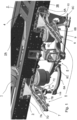
- FIG. 1 the parts relevant for describing an embodiment of a road vehicle according to the invention are schematically shown in perspective.
- Road vehicles provided with an electric motor configured to at least partially propel the road vehicle are known in the art and a detailed description thereof is omitted here for clarity sake.
- the road vehicle comprises a chassis 1 comprising a first elongate chassis beam 2 and a second elongate chassis beam 3, both extending along a length of the road vehicle, and at least one cross beam 4 connecting the first elongate chassis beam 2 and the second elongate chassis beam 3.
- a front side of the road vehicle is situated at the right hand side of the figure, whilst a rear side of the road vehicle is situated at the left hand side of figure 1 .
- the road vehicle further comprises a battery module mounting system 5 for mounting a battery module to the chassis 1.
- Each of the first and second elongate chassis beam 2, 3 comprises an inner surface (only the inner surface 2A of the first elongate chassis beam 2 being visible in Figure 1 ) and an outer surface (only the outer surface 3B of the second elongate chassis beam 3 being visible in Figure 1 ).
- the inner surfaces of the first and second chassis beams 2, 3 face each other while the outer surfaces of the first and second chassis beams 2, 3 face away from each other.
- the battery module mounting system 5 comprises a front bracket 6 mounted to and projecting from the outer surface 3B of the second elongate chassis beam 3 and a posterior bracket 7 mounted to and projecting from the outer surface 3B of the elongate chassis beam 3.
- the posterior bracket 7 is spaced apart from the front bracket 6 for receiving a battery module (not shown) between the front bracket 6 and the posterior bracket 7.
- the battery module can be attached to the front and posterior brackets by any known means in the art.
- Each of the front and posterior brackets 6, 7 is a triangularly shaped bracket comprising a chassis beam attachment portion 6A, 7A for connecting the triangularly shaped bracket 6, 7 to the outer surface 3B of the second elongate chassis beam 3.
- An angled portion 6B, 7B extends upwardly between a lower edge 6C, 7C of the chassis beam attachment portion 6A, 7A and an upper horizontal portion 6D, 7D of the triangularly shaped bracket 6, 7.
- a battery module can be arranged on the outer surface 3B of the second elongate chassis beam 3.
- another battery module can be arranged on the outer surface of the first elongate chassis beam 2, and that the invention is not restricted to the number of battery modules.
- the road vehicle comprises a suspension system 8 connecting the chassis 1 to an axle onto which wheels (both not shown for clarity reasons) of the road vehicle are attached.
- the suspension system 8 comprises a first suspension sub unit 8A and a second suspension sub unit 8B (see e.g. Fig. 2 ) connected with each other by a connection rod 8C.
- the first suspension sub unit 8 comprises a longitudinal rod 9 configured to longitudinally limit a movement of the axle.
- the second suspension sub unit 8B (part of which is depicted in e.g. Fig. 2 ) is identical to the first suspension sub unit 8A).
- the longitudinal rod 9 is connected to the second elongate chassis beam 3 via a front hanger 10 extending downwards from the second elongate chassis beam 3.
- the first suspension sub unit 8 further comprises a suspension element configured to limit a vertical movement of the axle, which suspension element according to the invention is a stabilizer rod 11 having an upper end 11A and a lower end 11B, the upper end 11A of the stabilizer rod 11 being attached to the lower edge 7C of the chassis beam attachment portion 7A of the posterior bracket 7.
- the front bracket 6 and the front hanger 10 are integrated in one piece so that an even more compact arrangement of the first suspension sub unit 8A and thus the suspension system 8 and the battery module mounting system 5 can be achieved.
- the stabilizer rod 10 is relatively short and thus a relatively short suspension stroke length is obtained this can, if desired and needed, be compensated by e.g. controlling the suspension parameters, such as e.g. the air pressure in an air suspension system.
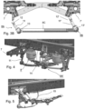
- FIGs 2 and 3A / 3B the posterior portion of the battery module mounting system and the suspension system 8 are shown in a perspective view and front view, respectively, depicting both suspension sub units 8A and 8B of the embodiment of Figure 1 of a road vehicle according to an embodiment of the invention without depicting the elongate chassis beams for clarity reasons.
- the components of the second suspension sub unit 8B are indicated with the same reference numerals as for the first suspension sub unit but an " ' " has been added.
- the upper end 11A, 11A' of the stabilizer rod 11, 11' is attached to the lower edge of the chassis beam attachment portion of the posterior bracket 7, 7' by means of a first ball joint 12, 12'.
- the lower end 11B, 11B' of the stabilizer rod 11, 11' is attached to the connection rod 8C by means of a second ball joint 13, 13'.
- the ball joints 12, 12'; 13, 13' provide that the suspension system 8 can allow for movements of the chassis relative to the axle in all directions to a greater extent. This is e.g. shown in Fig. 3B which depicts the situation in which during rolling of the axle the connection rod 8C winds itself leading to a difference in vertical height of the ball joints 12, 13; 12', 13' which has as result that the connection rod 8C moves sideways with regard to the chassis.
- the suspension system 8 is an air suspension system 8' and comprises a driving height control valve 14 arranged between a respective elongate chassis beam 3 and the corresponding suspension sub unit 8A'.
- the driving height control valve 14 is arranged to prevent an overstretch of the stabilizer rod 11 in case of large relative movements between chassis and axle.
- a catch cable 15 can be used as shown in Fig. 5 .
Landscapes
- Engineering & Computer Science (AREA)
- Mechanical Engineering (AREA)
- Chemical & Material Sciences (AREA)
- Combustion & Propulsion (AREA)
- Transportation (AREA)
- Vehicle Body Suspensions (AREA)
- Arrangement Or Mounting Of Propulsion Units For Vehicles (AREA)
- Body Structure For Vehicles (AREA)
Applications Claiming Priority (1)
| Application Number | Priority Date | Filing Date | Title |
|---|---|---|---|
| NL2035222A NL2035222B1 (en) | 2023-06-29 | 2023-06-29 | A road vehicle |
Publications (3)
| Publication Number | Publication Date |
|---|---|
| EP4484183A1 true EP4484183A1 (de) | 2025-01-01 |
| EP4484183C0 EP4484183C0 (de) | 2025-07-23 |
| EP4484183B1 EP4484183B1 (de) | 2025-07-23 |
Family
ID=87514363
Family Applications (1)
| Application Number | Title | Priority Date | Filing Date |
|---|---|---|---|
| EP24185444.7A Active EP4484183B1 (de) | 2023-06-29 | 2024-06-28 | Strassenfahrzeug |
Country Status (2)
| Country | Link |
|---|---|
| EP (1) | EP4484183B1 (de) |
| NL (1) | NL2035222B1 (de) |
Citations (4)
| Publication number | Priority date | Publication date | Assignee | Title |
|---|---|---|---|---|
| WO2022084936A1 (en) | 2020-10-22 | 2022-04-28 | Iveco Magirus Ag | Improved front hanger for a heavy vehicle suspension system |
| WO2022255870A1 (en) * | 2021-06-01 | 2022-12-08 | Daf Trucks N.V. | Pre-assembled electric power module |
| DE102022128747A1 (de) * | 2022-10-28 | 2022-12-29 | Daimler Truck AG | Nutzfahrzeug |
| WO2022269461A1 (en) * | 2021-06-21 | 2022-12-29 | Iveco Magirus Ag | Improved braket for a suspension system of a heavy vehicle |
-
2023
- 2023-06-29 NL NL2035222A patent/NL2035222B1/en active
-
2024
- 2024-06-28 EP EP24185444.7A patent/EP4484183B1/de active Active
Patent Citations (4)
| Publication number | Priority date | Publication date | Assignee | Title |
|---|---|---|---|---|
| WO2022084936A1 (en) | 2020-10-22 | 2022-04-28 | Iveco Magirus Ag | Improved front hanger for a heavy vehicle suspension system |
| WO2022255870A1 (en) * | 2021-06-01 | 2022-12-08 | Daf Trucks N.V. | Pre-assembled electric power module |
| WO2022269461A1 (en) * | 2021-06-21 | 2022-12-29 | Iveco Magirus Ag | Improved braket for a suspension system of a heavy vehicle |
| DE102022128747A1 (de) * | 2022-10-28 | 2022-12-29 | Daimler Truck AG | Nutzfahrzeug |
Also Published As
| Publication number | Publication date |
|---|---|
| EP4484183C0 (de) | 2025-07-23 |
| NL2035222B1 (en) | 2025-01-09 |
| EP4484183B1 (de) | 2025-07-23 |
Similar Documents
| Publication | Publication Date | Title |
|---|---|---|
| JP2003515489A (ja) | 車両のリジッドアクスルのための車軸懸架装置 | |
| US20040140641A1 (en) | Rear axle of a passenger vehicle with five individual links | |
| CN100579851C (zh) | 具有剪式伸缩机构的悬挂装置 | |
| US12030374B2 (en) | Bearing arrangement of a component on an axle carrier for a motor vehicle, and motor vehicle, in particular passenger car | |
| US9446797B2 (en) | Front vehicle-body structure of vehicle | |
| CN104010922A (zh) | 汽车的前副车架结构 | |
| CN1273317C (zh) | 用于车辆的变速箱安装结构 | |
| KR20050085946A (ko) | 다용도 차량을 위한 전방프레임부품 | |
| KR20180101448A (ko) | 휠 서스펜션 | |
| KR20180101447A (ko) | 휠 서스펜션 | |
| US20200140008A1 (en) | Axle Support with Device for Positioning a Steering Gear | |
| US6354627B1 (en) | Construction for suspension system mounting portions of body of vehicle | |
| EP4484183A1 (de) | Strassenfahrzeug | |
| JP2009166796A (ja) | 車両のサスペンション装置 | |
| EP1241077B1 (de) | Lastkraftwagen mit niedrigem, ebenem Fahrerhausboden | |
| US20130088047A1 (en) | Vehicle body comprising a longitudinal member and an elastomer bearing arranged thereon, especially as a transmission mounting | |
| EP1400380B1 (de) | Fahrzeugradaufhängung mit Querblattfeder | |
| JP6873226B2 (ja) | 車両のステアリングコラム用の支持装置およびこのような支持装置を備えた車両 | |
| JP4133723B2 (ja) | 自動車の前部車体構造 | |
| CN210126555U (zh) | 铝合金前副车架 | |
| EP4257454B1 (de) | Strassenfahrzeug mit batteriebefestigung | |
| CN107264218B (zh) | 具有横向稳定杆的车轴悬架系统和具有车轴悬架系统的车辆 | |
| CN113492913B (zh) | 副车架以及车辆 | |
| JP3440867B2 (ja) | 電気自動車の車体下部構造 | |
| KR910003949B1 (ko) | 차량의 프론트휘일 서스펜션구조 |
Legal Events
| Date | Code | Title | Description |
|---|---|---|---|
| PUAI | Public reference made under article 153(3) epc to a published international application that has entered the european phase |
Free format text: ORIGINAL CODE: 0009012 |
|
| STAA | Information on the status of an ep patent application or granted ep patent |
Free format text: STATUS: REQUEST FOR EXAMINATION WAS MADE |
|
| 17P | Request for examination filed |
Effective date: 20240628 |
|
| AK | Designated contracting states |
Kind code of ref document: A1 Designated state(s): AL AT BE BG CH CY CZ DE DK EE ES FI FR GB GR HR HU IE IS IT LI LT LU LV MC ME MK MT NL NO PL PT RO RS SE SI SK SM TR |
|
| GRAP | Despatch of communication of intention to grant a patent |
Free format text: ORIGINAL CODE: EPIDOSNIGR1 |
|
| STAA | Information on the status of an ep patent application or granted ep patent |
Free format text: STATUS: GRANT OF PATENT IS INTENDED |
|
| RIC1 | Information provided on ipc code assigned before grant |
Ipc: B62D 21/11 20060101ALI20250212BHEP Ipc: B60K 1/04 20190101ALI20250212BHEP Ipc: B60G 21/055 20060101AFI20250212BHEP |
|
| INTG | Intention to grant announced |
Effective date: 20250224 |
|
| GRAS | Grant fee paid |
Free format text: ORIGINAL CODE: EPIDOSNIGR3 |
|
| GRAA | (expected) grant |
Free format text: ORIGINAL CODE: 0009210 |
|
| STAA | Information on the status of an ep patent application or granted ep patent |
Free format text: STATUS: THE PATENT HAS BEEN GRANTED |
|
| AK | Designated contracting states |
Kind code of ref document: B1 Designated state(s): AL AT BE BG CH CY CZ DE DK EE ES FI FR GB GR HR HU IE IS IT LI LT LU LV MC ME MK MT NL NO PL PT RO RS SE SI SK SM TR |
|
| REG | Reference to a national code |
Ref country code: GB Ref legal event code: FG4D |
|
| REG | Reference to a national code |
Ref country code: CH Ref legal event code: EP |
|
| REG | Reference to a national code |
Ref country code: DE Ref legal event code: R096 Ref document number: 602024000336 Country of ref document: DE |
|
| REG | Reference to a national code |
Ref country code: IE Ref legal event code: FG4D |
|
| U01 | Request for unitary effect filed |
Effective date: 20250730 |
|
| U07 | Unitary effect registered |
Designated state(s): AT BE BG DE DK EE FI FR IT LT LU LV MT NL PT RO SE SI Effective date: 20250808 |
|
| PG25 | Lapsed in a contracting state [announced via postgrant information from national office to epo] |
Ref country code: IS Free format text: LAPSE BECAUSE OF FAILURE TO SUBMIT A TRANSLATION OF THE DESCRIPTION OR TO PAY THE FEE WITHIN THE PRESCRIBED TIME-LIMIT Effective date: 20251123 |
|
| PG25 | Lapsed in a contracting state [announced via postgrant information from national office to epo] |
Ref country code: NO Free format text: LAPSE BECAUSE OF FAILURE TO SUBMIT A TRANSLATION OF THE DESCRIPTION OR TO PAY THE FEE WITHIN THE PRESCRIBED TIME-LIMIT Effective date: 20251023 |
|
| PG25 | Lapsed in a contracting state [announced via postgrant information from national office to epo] |
Ref country code: HR Free format text: LAPSE BECAUSE OF FAILURE TO SUBMIT A TRANSLATION OF THE DESCRIPTION OR TO PAY THE FEE WITHIN THE PRESCRIBED TIME-LIMIT Effective date: 20250723 |
|
| PG25 | Lapsed in a contracting state [announced via postgrant information from national office to epo] |
Ref country code: GR Free format text: LAPSE BECAUSE OF FAILURE TO SUBMIT A TRANSLATION OF THE DESCRIPTION OR TO PAY THE FEE WITHIN THE PRESCRIBED TIME-LIMIT Effective date: 20251024 |
|
| PG25 | Lapsed in a contracting state [announced via postgrant information from national office to epo] |
Ref country code: PL Free format text: LAPSE BECAUSE OF FAILURE TO SUBMIT A TRANSLATION OF THE DESCRIPTION OR TO PAY THE FEE WITHIN THE PRESCRIBED TIME-LIMIT Effective date: 20250723 |
|
| PG25 | Lapsed in a contracting state [announced via postgrant information from national office to epo] |
Ref country code: RS Free format text: LAPSE BECAUSE OF FAILURE TO SUBMIT A TRANSLATION OF THE DESCRIPTION OR TO PAY THE FEE WITHIN THE PRESCRIBED TIME-LIMIT Effective date: 20251023 |
|
| PG25 | Lapsed in a contracting state [announced via postgrant information from national office to epo] |
Ref country code: ES Free format text: LAPSE BECAUSE OF FAILURE TO SUBMIT A TRANSLATION OF THE DESCRIPTION OR TO PAY THE FEE WITHIN THE PRESCRIBED TIME-LIMIT Effective date: 20250723 |
|
| PG25 | Lapsed in a contracting state [announced via postgrant information from national office to epo] |
Ref country code: SM Free format text: LAPSE BECAUSE OF FAILURE TO SUBMIT A TRANSLATION OF THE DESCRIPTION OR TO PAY THE FEE WITHIN THE PRESCRIBED TIME-LIMIT Effective date: 20250723 |