EP4484031A1 - Submerged entry nozzle for continuous casting, and continuous casting method for steel - Google Patents
Submerged entry nozzle for continuous casting, and continuous casting method for steel Download PDFInfo
- Publication number
- EP4484031A1 EP4484031A1 EP23778873.2A EP23778873A EP4484031A1 EP 4484031 A1 EP4484031 A1 EP 4484031A1 EP 23778873 A EP23778873 A EP 23778873A EP 4484031 A1 EP4484031 A1 EP 4484031A1
- Authority
- EP
- European Patent Office
- Prior art keywords
- immersion nozzle
- mold
- discharge
- continuous casting
- molten steel
- Prior art date
- Legal status (The legal status is an assumption and is not a legal conclusion. Google has not performed a legal analysis and makes no representation as to the accuracy of the status listed.)
- Granted
Links
Images

Classifications
-
- B—PERFORMING OPERATIONS; TRANSPORTING
- B22—CASTING; POWDER METALLURGY
- B22D—CASTING OF METALS; CASTING OF OTHER SUBSTANCES BY THE SAME PROCESSES OR DEVICES
- B22D41/00—Casting melt-holding vessels, e.g. ladles, tundishes, cups or the like
- B22D41/50—Pouring-nozzles
- B22D41/58—Pouring-nozzles with gas injecting means
-
- B—PERFORMING OPERATIONS; TRANSPORTING
- B22—CASTING; POWDER METALLURGY
- B22D—CASTING OF METALS; CASTING OF OTHER SUBSTANCES BY THE SAME PROCESSES OR DEVICES
- B22D11/00—Continuous casting of metals, i.e. casting in indefinite lengths
- B22D11/001—Continuous casting of metals, i.e. casting in indefinite lengths of specific alloys
-
- B—PERFORMING OPERATIONS; TRANSPORTING
- B22—CASTING; POWDER METALLURGY
- B22D—CASTING OF METALS; CASTING OF OTHER SUBSTANCES BY THE SAME PROCESSES OR DEVICES
- B22D11/00—Continuous casting of metals, i.e. casting in indefinite lengths
- B22D11/04—Continuous casting of metals, i.e. casting in indefinite lengths into open-ended moulds
- B22D11/049—Continuous casting of metals, i.e. casting in indefinite lengths into open-ended moulds for direct chill casting, e.g. electromagnetic casting
-
- B—PERFORMING OPERATIONS; TRANSPORTING
- B22—CASTING; POWDER METALLURGY
- B22D—CASTING OF METALS; CASTING OF OTHER SUBSTANCES BY THE SAME PROCESSES OR DEVICES
- B22D11/00—Continuous casting of metals, i.e. casting in indefinite lengths
- B22D11/10—Supplying or treating molten metal
-
- B—PERFORMING OPERATIONS; TRANSPORTING
- B22—CASTING; POWDER METALLURGY
- B22D—CASTING OF METALS; CASTING OF OTHER SUBSTANCES BY THE SAME PROCESSES OR DEVICES
- B22D11/00—Continuous casting of metals, i.e. casting in indefinite lengths
- B22D11/10—Supplying or treating molten metal
- B22D11/11—Treating the molten metal
- B22D11/114—Treating the molten metal by using agitating or vibrating means
- B22D11/115—Treating the molten metal by using agitating or vibrating means by using magnetic fields
-
- B—PERFORMING OPERATIONS; TRANSPORTING
- B22—CASTING; POWDER METALLURGY
- B22D—CASTING OF METALS; CASTING OF OTHER SUBSTANCES BY THE SAME PROCESSES OR DEVICES
- B22D41/00—Casting melt-holding vessels, e.g. ladles, tundishes, cups or the like
- B22D41/50—Pouring-nozzles
Definitions
- the present invention relates to an immersion nozzle for pouring molten steel into a mold when continuously casting the molten steel, and to a continuous casting method for steel using this immersion nozzle.
- the present invention relates to an immersion nozzle for continuous casting and a continuous casting method for steel that can inhibit both capture, in a solidified shell, of bubbles of an inert gas blown into the immersion nozzle and entrapment of a mold powder in the solidified shell.
- Criteria for determining the quality of a cast piece of steel produced by a continuous casting machine include the following two. The first one is that the amount of bubbles of an inert gas, such as an argon gas, captured in the cast piece after being blown into molten steel flowing down inside an immersion nozzle is small. The second one is that the amount of a mold powder captured in the cast piece after being added to a meniscus (the bath surface of the molten steel inside the mold) is small. As the bubbles of the inert gas and the mold powder that have been captured in the cast piece constitute surface defects of the steel product, reducing these amounts is important.
- an inert gas such as an argon gas
- an immersion nozzle having discharge ports facing the left and right short sides of the mold is generally used. Therefore, a discharge flow of molten steel discharged through each discharge port of the immersion nozzle collides with a solidified shell on the side of the short side of the mold (cast piece short-side solidified shell) and diverges upward and downward after the collision.
- One of the divergent flows forms a flow heading toward the lower side of the mold (hereinafter referred to as a "descending divergent flow”), while the other forms a flow heading toward the meniscus at an upper part (hereinafter referred to as an "ascending divergent flow").
- the ascending divergent flow heading toward the meniscus forms an ascending flow along the short-side solidified shell of the slab cast piece (hereinafter referred to as an "ascending short-side flow").
- This ascending short-side flow significantly influences the flow velocity of the molten steel in the meniscus. Specifically, the faster the ascending divergent flow becomes, the faster the ascending short-side flow becomes, and as the flow velocity of the ascending short-side flow increases, the flow velocity of the molten steel in the meniscus becomes higher. As a result, the frequency of entrapment of the mold powder present on the meniscus in the solidified shell increases.
- one problem in reducing defects due to the mold powder is how to decelerate the ascending divergent flow after the collision with the cast piece short-side solidified shell.
- the descending divergent flow heading toward the lower side of the mold forms a descending flow along the short-side solidified shell of the slab cast piece (hereinafter referred to as a "descending short-side flow").
- This descending short-side flow reaches deep inside an unsolidified layer.
- the faster the descending divergent flow becomes the faster the descending short-side flow becomes, leading to an increase in the depth of penetration of the descending short-side flow into the unsolidified layer.
- An inert gas such as an argon gas, that has been blown into the molten steel flowing down inside the immersion nozzle to prevent adhesion of alumina to an inner wall of the immersion nozzle turns into bubbles and is discharged through the discharge ports of the immersion nozzle into the molten steel inside the mold.
- one problem in reducing the amount of bubbles of the inert gas captured in the cast piece is how to decelerate the descending divergent flow after the collision with the cast piece short-side solidified shell.
- Patent Literature 1 discloses an immersion nozzle for continuous casting which has, at a portion of the immersion nozzle to be immersed in molten steel, a plurality of upper and lower discharge ports formed such that the opening part area of the discharge port provided on the lower side becomes smaller than the opening part area of the discharge port provided on the upper side, and in which the inside diameter of a molten steel flow passage inside the immersion nozzle is smaller in a range where the discharge ports are provided than in an upper part where discharge ports are not provided.
- Patent Literature 1 alleges that discharge flows from the discharge ports can be made into slow uniform flows, and that thereby the descending short-side flow can be weakened to reduce the amounts of bubbles of an inert gas and non-metallic inclusions entrapped in a cast piece.
- Patent Literature 2 discloses an immersion nozzle for continuous casting that has, at a portion of the immersion nozzle to be immersed in molten steel, four discharge ports consisting of a left-row, upper-tier port, a left-row, lower-tier port, a right-row, upper-tier port, and a right-row, lower-tier port.
- the opening part area of each lower-tier discharge port is smaller than the opening part area of each upper-tier discharge port.
- a ratio of the opening part area of each lower-tier discharge port to a total of the opening part areas of the upper-tier and lower-tier discharge ports is between 0.2 and 0.4 inclusive.
- the discharge angles of the lower-tier discharge ports are 10° or more downward based on the discharge angles of the upper-tier discharge ports.
- Patent Literature 2 alleges that the flow velocity of the molten steel near an inner wall on the side of a cast piece short-side solidified shell can be sufficiently controlled, and that thereby bubbles of an inert gas and non-metallic inclusions can be inhibited from penetrating to a deep part of the cast piece through the descending short-side flow to obtain a cast piece with few internal defects.
- Patent Literature 3 discloses an immersion nozzle having, at a portion to be immersed into molten steel inside a mold, two or more pairs of discharge ports that are bilaterally symmetrical with respect to an axial center of the immersion nozzle.
- the opening part area of the discharge port located on the lower side is equal to or larger than the opening part area of the discharge port located on the upper side.
- the discharge angle of each discharge port is limited to a maximum of 15° upward relative to the horizontal direction and a maximum of 50° downward relative to the horizontal direction.
- the discharge port located on the lower side has a discharge angle that is a downward angle larger than the discharge angle of the discharge port located on the upper side, and the difference between the discharge angle of the discharge port located on the lower side and the discharge angle of the discharge port located on the upper side is between 20° and 55° inclusive.
- the discharge angle of each discharge port is preferably within a range of 10° upward to 45° downward.
- the discharge angle of the discharge port provided on the lower side and the discharge angle of the discharge port provided on the upper side are the same. Thus, no difference is provided between the discharge angle of the discharge port provided on the lower side and the discharge angle of the discharge port provided on the upper side. Therefore, discharge flows discharged through the upper and lower discharge ports merge, so that an ideal damping effect on the discharge flows can hardly be achieved.
- the opening part area of the lower discharge port is smaller than the opening part area of the upper discharge port, and the difference between the discharge angle of the lower discharge port and the discharge angle of the upper discharge port is small. For these reasons, the flow velocity of the molten steel in the meniscus becomes high, leading to a high chance of the occurrence of the entrapment of the mold powder.
- Patent Literature 3 mentions angles of the discharge ports, there is no specific description of the relationship between the straight-body-part internal cross-sectional area of the immersion nozzle and the areas of the discharge ports. Thus, specific conditions are unknown, and it is doubtful that an improving effect can be actually achieved.
- the present invention has been developed in view of these circumstances, and an object thereof is to provide an immersion nozzle for continuous casting that improves the quality of a cast piece when pouring molten steel into a mold for continuous casting in continuous casting of steel.
- the object is to stably inhibit the capture, in the cast piece, of bubbles of an inert gas, such as an argon gas, having been blown into the molten steel flowing down inside the immersion nozzle, as well as to stably inhibit the capture, in the cast piece, of a mold powder having been added to the meniscus.
- Another object is to provide a steel continuous casting method that uses the immersion nozzle.
- An immersion nozzle for continuous casting according to the present invention for solving the above-described problems is an immersion nozzle for continuous casting which has a shape of a cylinder with a bottom and through which molten steel is poured into a mold for continuous casting.
- This immersion nozzle has the following characteristics.
- the immersion nozzle has, at a portion to be immersed in the molten steel inside the mold for continuous casting, two or more pairs of discharge ports that are axially symmetrical with respect to an axial center of the immersion nozzle.
- an inside diameter in a range from an upper end of an upper discharge port to a bottom of the immersion nozzle is equal to or smaller than that at other portions.
- a ratio of a straight-body-part internal cross-sectional area (S1) in a range from an upper end of the immersion nozzle to the upper end of the upper discharge port to a total one-side opening part area (S3 + S4) of the discharge ports is within a range of 0.30 to 0.50;
- a ratio of a straight-body-part internal cross-sectional area (S2) in a range from the upper end of the upper discharge port to the bottom of the immersion nozzle to the total one-side opening part area (S3 + S4) of the discharge ports is within a range of 0.10 to 0.40;
- the straight-body-part internal cross-sectional areas (S1, S2) of the immersion nozzle and the one-side opening areas (S3, S4) of the discharge ports meet a relationship 0.20 ⁇ (S2/S4) ⁇ (S1/S3) ⁇ 1.0.
- a discharge angle of each of the discharge ports is within a range of +20° to -50°, with an upward direction based on a horizontal plane being positive.
- the discharge angle of the discharge port on a vertically lower side is vertically downward within a range of 20° to 55° based on the discharge angle of the discharge port on a vertically upper side.
- the immersion nozzle for continuous casting according to the present invention could be a more preferable solution when two of the discharge ports with a vertical positional relationship face different directions in the horizontal plane, and at least one pair of the discharge ports faces a direction parallel to a long-side surface of the mold.
- a steel continuous casting method is characterized in that: the above-described immersion nozzle is used; a mold powder is added to a surface of molten steel inside a mold for continuous casting; and molten steel inside a tundish is poured into the mold through the immersion nozzle, while an inert gas is blown into molten steel flowing down the molten steel flow passage of the immersion nozzle.
- the steel continuous casting method according to the present invention could be a more preferable solution when, for example:
- molten steel discharged through the upper and lower discharge ports of the immersion nozzle is kept at an appropriate discharge flow rate, and moreover, the discharge flows discharged through the upper and lower discharge ports collide with the cast piece short-side solidified shell without merging.
- a descending divergent flow, after the collision with the cast piece short-side solidified shell, of the discharge flow from the discharge port located on the upper side and an ascending divergent flow, after the collision with the cast piece short-side solidified shell, of the discharge flow from the discharge port located on the lower side collide with each other, thereby each dampening the other's flow velocity.
- the descending short-side flow that influences the capture of bubbles of an inert gas in the cast piece is mainly formed by the descending divergent flow, after the collision with the cast piece short-side solidified shell, of the discharge flow discharged through the discharge port on the vertically lowermost side.
- the ascending short-side flow that influences the flow velocity of the molten steel in the meniscus that is a determining factor in the entrapment of the mold powder is mainly formed by the ascending divergent flow, after the collision with the cast piece short-side solidified shell, of the discharge flow discharged through the discharge port on the vertically uppermost side.
- both the ascending short-side flow and the descending short-side flow can be decelerated, which makes it possible to stably inhibit both the entrapment of the mold powder and capture of bubbles of the inert gas in the cast piece. Therefore, the quality of the cast piece can be improved when pouring molten steel into a mold for continuous casting using the immersion nozzle according to the present invention in continuous casting of steel.
- the cast piece width is far larger than the cast piece thickness, and slab cast pieces with various cast piece widths are needed.
- the cast piece width/cast piece thickness ratio is often within a range of about 4 to 12.
- a mold for continuous casting commensurate with the dimensions of the lateral cross-section of the slab cast piece to be cast is used.
- the mold for continuous casting has one pair of mold long sides facing each other and one pair of mold short sides facing each other, and is configured such that the mold short sides are movable on the inner side of the mold long sides.
- an immersion nozzle for pouring molten steel into this mold for continuous casting an immersion nozzle having one or more pairs of discharge ports that face one pair of mold short sides facing each other is used.
- the molten steel is poured through each discharge port toward each mold short side. Therefore, the discharge flow of the molten steel discharged through each discharge port collides with a solidified shell on the side of the mold short side, i.e., a cast piece short-side solidified shell, and diverges upward and downward after the collision.
- One of the divergent flows forms a flow heading toward the lower side of the mold, i.e., a descending divergent flow.
- the other divergent flow forms a flow heading toward the meniscus at an upper part, i.e., an ascending divergent flow.
- the ascending divergent flow heading toward the meniscus forms an ascending flow along the short-side solidified shell of the slab cast piece, i.e., an ascending short-side flow.
- the descending divergent flow heading toward the lower side of the mold forms a descending flow along the short-side solidified shell of the slab cast piece, i.e., a descending short-side flow.
- the present inventors considered an immersion nozzle that could decelerate both the descending short-side flow and the ascending short-side flow in such a slab continuous casting machine. As a result, we found that an immersion nozzle having the following shape was optimal.
- the immersion nozzle according to this embodiment is a refractory having a shape of a cylinder with a bottom through which molten steel is poured into a mold for continuous casting.
- the immersion nozzle has, at a portion to be immersed in the molten steel inside the mold for continuous casting, two or more pairs of discharge ports that are bilaterally symmetrical with respect to an axial center of the immersion nozzle.
- an inside diameter in a range from an upper end of an upper discharge port to a bottom of the immersion nozzle is equal to or smaller than that at other portions.
- the discharge angle of the discharge port on the vertically lower side is vertically downward within a range of 20° to 55° based on the discharge angle of the discharge port on the vertically upper side.
- the discharge angle of the discharge port refers to an angle formed between a central axis of the discharge port and a horizontal plane, and being upward means being positive.
- the immersion nozzle according to this embodiment has, at the portion to be immersed in the molten steel inside the mold for continuous casting, two or more pairs of discharge ports that are axially symmetrical with respect to the axial center of the immersion nozzle. This is because when the immersion nozzle has two or more pairs of axially symmetrical discharge ports, discharge flows discharged through the discharge ports are dispersed and the flow velocities of the discharge flows decrease. Thus, both the descending divergent flow and the ascending divergent flow that are formed after the discharge flows collide with the cast piece short-side solidified shell decelerate.
- the inside diameter in the range from the upper end of the upper discharge port to the bottom of the immersion nozzle is equal to or smaller than that at other portions.
- the discharge ports disposed one above the other are within the range of +20° to -50°. This is because if the discharge angles of the discharge ports are set to be upward beyond 20° upward relative to the horizontal direction, the discharge flow from the discharge port provided on the vertically uppermost side may fail to collide with the cast piece short-side solidified shell and directly head for the meniscus without being decelerated.
- the discharge angles of the discharge ports should be within the range of +20° to -50°.
- the discharge angle of the discharge port located on the lower side should have a downward angle larger than the discharge angle of the discharge port located on the upper side, and the difference between the discharge angle of the discharge port located on the lower side and the discharge angle of the discharge port located on the upper side should be between 20° and 55° inclusive.
- These specifications are to prevent the discharge flow from the discharge port located on the upper side and the discharge flow from the discharge port located on the lower side from merging before colliding with the cast piece short-side solidified shell. If the difference in the discharge angle is smaller than 20°, the discharge flows from the two discharge ports may merge.
- the discharge flow from the discharge port located on the lower side may collide with the cast piece short-side solidified shell below the lower end of the mold, and the depth of penetration of the descending short-side flow may increase.
- the discharge flow from the discharge port located on the upper side may collide with the cast piece short-side solidified shell immediately below the meniscus, and the ascending short-side flow may become faster.
- the two discharge ports with a vertical positional relationship face different directions in the horizontal plane, and that at least one pair of the discharge ports faces a direction parallel to a long-side surface of the mold. That the discharge flow from the upper discharge port and the discharge flow from the lower discharge port are oriented in different directions in the horizontal plane is preferable, because then the likelihood that the discharge flows may interfere with each other and merge decreases and the dispersing effect on the discharge flows is enhanced.
- the different directions in the horizontal plane should be less than 90° apart at a maximum.
- Fig. 1 shows the immersion nozzle for continuous casting according to one embodiment of the present invention.
- Fig. 1 (a) is a longitudinal sectional view as cut along a plane including a central axis C of an immersion nozzle 1 and a central axes of discharge ports 2, and
- Fig. 1 (b) is a perspective view as seen from an obliquely upper side facing the discharge ports 2.
- the immersion nozzle 1 of the embodiment shown in Fig. 1 is the immersion nozzle 1 having two pairs of discharge ports 2 that are axially symmetrical with respect to the axial center C of the immersion nozzle 1, one vertically above the other at a portion to be immersed in molten steel.
- FIG. 1 is the immersion nozzle; 2 is the discharge ports; 3 is discharge ports located on the vertically upper side (hereinafter referred to as “upper discharge ports”); 4 is discharge ports located on the vertically lower side (hereinafter referred to as “lower discharge ports”); 5 is a molten steel flow passage provided inside the immersion nozzle 1; 6 is a bottom of the immersion nozzle 1; 7 is an upper end position of the immersion nozzle 1; 8 is an upper end position of the upper discharge ports 3; ⁇ is a discharge angle of the upper discharge ports 3; ⁇ is a discharge angle of the lower discharge ports 4; S 1 is an area of the molten steel flow passage in a range from the upper end position 7 of the immersion nozzle 1 to the upper end position 8 of the upper discharge ports 3 (straight-body-part internal cross-sectional area); S2 is an area of the molten steel flow passage in a range from the upper end position 8 of the upper discharge ports 3 to the bottom 6 of the immersion nozzle 1 (
- the upper discharge ports 3 correspond to the discharge ports 2 provided on the vertically uppermost side
- the lower discharge ports 4 correspond to the discharge ports 2 provided on the vertically lowermost side.
- the upper discharge ports 3 and the lower discharge ports 4 are oriented in the same direction in a horizontal plane.
- the immersion nozzle 1 of this embodiment is configured as described above. In the following, a steel continuous casting method using the immersion nozzle 1 according to this embodiment thus configured will be described.
- the immersion nozzle 1 is installed at the bottom of a tundish, and the tundish is installed above a mold for continuous casting such that the immersion nozzle 1 is located nearly at the center of the space inside the mold.
- molten steel produced in a refining furnace such as a converter
- the molten steel is poured from the tundish into the mold for continuous casting through the immersion nozzle 1.
- a mold powder is added to a meniscus, i.e., the bath surface of the molten steel inside the mold so as to cover the surface of the molten steel inside the mold.
- An inert gas such as an argon gas or a nitrogen gas, is blown into the molten steel flowing down the molten steel flow passage 5 of the immersion nozzle 1 through a sliding nozzle or a tundish upper nozzle.
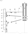
- Fig. 2 is a view schematically showing a result of a study on a flow inside a mold in a water model experiment simulating a flow of molten steel inside a mold that was performed using the immersion nozzle 1 of this embodiment in which two pairs of discharge ports 2 were each vertically arranged.
- the flow of the molten steel inside the mold will be described based on Fig. 2 .
- Fig. 2 shows only half of the mold for continuous casting on one side, half thereof on the other side has the same form, with the central axis C being an axis of symmetry.
- FIG. 2 Reference signs in Fig. 2 denote as follows: 9 is a mold short side; 10 is the bath surface inside the mold (corresponding to the meniscus); 11 is a discharge flow from the upper discharge port 3; 12 is a discharge flow from the lower discharge port 4; 13 is an ascending divergent flow formed as the discharge flow 11 from the upper discharge port 3 diverges; 14 is a descending divergent flow formed as the discharge flow 11 from the upper discharge port 3 diverges; 15 is an ascending divergent flow formed as the discharge flow 12 from the lower discharge port 4 diverges; 16 is a descending divergent flow formed as the discharge flow 12 from the lower discharge port 4 diverges; 17 is an ascending short-side flow flowing along the mold short side 9; 18 is a descending short-side flow flowing along the mold short side 9; and 19 is a meniscus flow.
- FIG. 2 the same parts as in Fig. 1 are denoted by the same reference signs while description thereof will be omitted.
- reference signs 20 and 21 are a flow velocity meter-sensor that measures the flow velocity of the meniscus flow 19 and a flow velocity meter-sensor that measures the flow velocity of the descending short-side flow 18, respectively, in the water model experiment.
- the discharge flow 11 and the discharge flow 12 are represented by straight lines, but the discharge flow 11 and the discharge flow 12 in reality flow toward the mold short side 9 while moving up and down as time passes.
- the discharge flow 11 discharged through the upper discharge port 3 and the discharge flow 12 discharged through the lower discharge port 4 collide with the mold short side 9 without merging in a range before colliding with the mold short side 9.
- the discharge flow 11 diverges into the ascending divergent flow 13 and the descending divergent flow 14, and the discharge flow 12 diverges into the ascending divergent flow 15 and the descending divergent flow 16.
- the discharge flow is dispersed into the two of the discharge flow 11 and the discharge flow 12.
- the flow velocity of each of the ascending divergent flow 13, the descending divergent flow 14, the ascending divergent flow 15, and the descending divergent flow 16 is reduced compared with an ascending divergent flow and a descending divergent flow in the case where there is one pair of discharge ports 2 (only one discharge port on one side). Further, the descending divergent flow 14 and the ascending divergent flow 15 are flows facing opposite directions, and the descending divergent flow 14 and the ascending divergent flow 15 collide and interfere with each other and thereby decelerate.
- the ascending short-side flow 17 that influences the meniscus flow 19 that is a determining factor in the entrapment of the mold powder is mainly determined by the flow velocity of the ascending divergent flow 13 while being little influenced by the ascending divergent flow 15. Since the ascending divergent flow 13 is decelerated compared with the velocity of the ascending divergent flow in the case of one pair of discharge ports 2, the ascending short-side flow 17 is decelerated, and thereby the flow velocity of the meniscus flow 19 is reduced.
- the descending short-side flow 18 that influences the capture of gas bubbles in the cast piece is mainly determined by the flow velocity of the descending divergent flow 16 while being little influenced by the descending divergent flow 14. Since the descending divergent flow 16 is decelerated compared with the velocity of the descending divergent flow in the case of one pair of discharge ports 2, the flow velocity of the descending short-side flow 18 decreases.
- both the meniscus flow 19 that influences the entrapment of the mold powder and the descending short-side flow 18 that influences the capture of gas bubbles in the cast piece are decelerated.
- both the entrapment of the mold powder and capture of bubbles of the inert gas in the cast piece can be stably inhibited.
- one pair of discharge ports 2 on the upper side and another pair of discharge ports 2 on the lower side are used. This may be changed so as to use two or more pairs of discharge ports 2 that discharge in different directions relative to the horizontal direction, at the same vertical position on either the upper side or the lower side.
- the opening cross-sectional areas of the discharge ports 2 should be the total opening area on one side relative to the central axis.
- both the ascending short-side flow 17 that influences the flow velocity of the molten steel in the meniscus that is a determining factor in the entrapment of the mold powder and the descending short-side flow 18 that influences the capture of bubbles of the inert gas in the cast piece can be decelerated.
- Continuous casting operation was performed in an actual slab continuous casting machine using the immersion nozzle 1 according to the embodiment (Invention Example).
- the lateral cross-section of a slab cast piece that was continuously cast had dimensions with a thickness of 220 to 260 mm and a width of 1000 to 2200 mm.
- An argon gas was used as an inert gas blown into the immersion nozzle 1, and an optimal mold powder according to the cast piece pulling speed and the type of steel was added to the surface of the molten steel inside the mold.
- an immersion nozzle having one pair of discharge ports on the left and right sides of the immersion nozzle, an immersion nozzle having two pairs of discharge ports on the left and right sides of the immersion nozzle, and an immersion nozzle in which conditions for providing two pairs of discharge ports were outside the range of the present invention were also used.
- molds for continuous casting were used: a mold in which no magnetic field generation device was installed; a mold in which direct-current magnetic field generation devices were installed on back surfaces of the mold for continuous casting so as to face each other across the long sides of the mold, in a total of two levels, one on each of the upper side of the upper discharge port and the lower side of the lower discharge port; and a mold in which alternating-current magnetic field generation devices were installed on the back surfaces of the mold for continuous casting so as to face each other across the long sides of the mold.
- a direct-current static magnetic field was applied from the direct-current magnetic field generation devices in the two upper and lower levels to the molten steel inside the mold, on the upper side of the upper discharge port and the lower side of the lower discharge port.
- an alternating-current moving magnetic field was applied from the alternating-current magnetic field generation devices to the molten steel inside the mold for continuous casting, and continuous casting was performed while the molten steel inside the mold was swirled in a horizontal direction in the meniscus.
- Slab cast pieces produced by the slab continuous casting machine were hot-rolled into hot-rolled steel sheets, and these hot-rolled steel sheets were inspected for surface defects caused by argon gas bubbles and mold powder. From these surface defects, argon gas bubbles and mold powder remaining in the cast piece were evaluated. Specifically, a steel product with a lower defect index was evaluated as having fewer argon gas bubbles and less mold powder remaining in the cast piece.
- Table 1 shows the conditions of the immersion nozzle
- Table 2 shows the operation conditions and the operation results. Designing the immersion nozzle within the range of the present invention resulted in lower ratios of inclusion of defects in the steel product.
- Table 1 No. Discharge Angle Area Ratio Remarks ⁇ ⁇ S1/(S3+S4) S2/(S3+S4) S1/S3 S2/S4 ⁇ ⁇ - - - - 1 +10 -25 0.3 0.1 0.1 0.1 Invention Example 2 +5 -30 0.3 0.1 0.1 0.1 Invention Example 3 0 -35 0.3 0.1 0.1 0.1 Invention Example 4 +10 -25 0.4 0.2 0.3 0.2 Invention Example 5 +5 -30 0.4 0.2 0.3 0.2 Invention Example 6 0 -35 0.4 0.2 0.3 0.2 Invention Example 7 +10 -25 0.5 0.3 0.5 0.4 Invention Example 8 +5 -30 0.5 0.3 0.5 0.4 Invention Example 9 0 -35 0.5 0.3 0.5 0.4 Invention
Landscapes
- Engineering & Computer Science (AREA)
- Mechanical Engineering (AREA)
- Continuous Casting (AREA)
- Casting Support Devices, Ladles, And Melt Control Thereby (AREA)
Abstract
Description
- The present invention relates to an immersion nozzle for pouring molten steel into a mold when continuously casting the molten steel, and to a continuous casting method for steel using this immersion nozzle. Specifically, the present invention relates to an immersion nozzle for continuous casting and a continuous casting method for steel that can inhibit both capture, in a solidified shell, of bubbles of an inert gas blown into the immersion nozzle and entrapment of a mold powder in the solidified shell.
- Criteria for determining the quality of a cast piece of steel produced by a continuous casting machine include the following two. The first one is that the amount of bubbles of an inert gas, such as an argon gas, captured in the cast piece after being blown into molten steel flowing down inside an immersion nozzle is small. The second one is that the amount of a mold powder captured in the cast piece after being added to a meniscus (the bath surface of the molten steel inside the mold) is small. As the bubbles of the inert gas and the mold powder that have been captured in the cast piece constitute surface defects of the steel product, reducing these amounts is important.
- When casting a slab cast piece using a continuous casting machine, an immersion nozzle having discharge ports facing the left and right short sides of the mold is generally used. Therefore, a discharge flow of molten steel discharged through each discharge port of the immersion nozzle collides with a solidified shell on the side of the short side of the mold (cast piece short-side solidified shell) and diverges upward and downward after the collision. One of the divergent flows forms a flow heading toward the lower side of the mold (hereinafter referred to as a "descending divergent flow"), while the other forms a flow heading toward the meniscus at an upper part (hereinafter referred to as an "ascending divergent flow").
- Of these flows, the ascending divergent flow heading toward the meniscus forms an ascending flow along the short-side solidified shell of the slab cast piece (hereinafter referred to as an "ascending short-side flow"). This ascending short-side flow significantly influences the flow velocity of the molten steel in the meniscus. Specifically, the faster the ascending divergent flow becomes, the faster the ascending short-side flow becomes, and as the flow velocity of the ascending short-side flow increases, the flow velocity of the molten steel in the meniscus becomes higher. As a result, the frequency of entrapment of the mold powder present on the meniscus in the solidified shell increases. Thus, one problem in reducing defects due to the mold powder is how to decelerate the ascending divergent flow after the collision with the cast piece short-side solidified shell.
- On the other hand, the descending divergent flow heading toward the lower side of the mold forms a descending flow along the short-side solidified shell of the slab cast piece (hereinafter referred to as a "descending short-side flow"). This descending short-side flow reaches deep inside an unsolidified layer. In this case, the faster the descending divergent flow becomes, the faster the descending short-side flow becomes, leading to an increase in the depth of penetration of the descending short-side flow into the unsolidified layer.
- An inert gas, such as an argon gas, that has been blown into the molten steel flowing down inside the immersion nozzle to prevent adhesion of alumina to an inner wall of the immersion nozzle turns into bubbles and is discharged through the discharge ports of the immersion nozzle into the molten steel inside the mold. Part of the bubbles of the inert gas discharged into the molten steel inside the mold penetrates to the lower side of the mold along with the descending divergent flow. The faster the descending divergent flow becomes, the faster the descending short-side flow becomes, which results in an increase in the depth of penetration of the bubbles of the inert gas into the unsolidified layer and an increase in the amount of bubbles of the inert gas captured in the cast piece. Thus, one problem in reducing the amount of bubbles of the inert gas captured in the cast piece is how to decelerate the descending divergent flow after the collision with the cast piece short-side solidified shell.
- Some measures have been proposed for these challenges, and as one such measure, a technology has been proposed that performs continuous casting using an immersion nozzle having a plurality of discharge ports at upper and lower positions on left and right sides of a part of the immersion nozzle to be immersed in molten steel.
- For example, Patent Literature 1 discloses an immersion nozzle for continuous casting which has, at a portion of the immersion nozzle to be immersed in molten steel, a plurality of upper and lower discharge ports formed such that the opening part area of the discharge port provided on the lower side becomes smaller than the opening part area of the discharge port provided on the upper side, and in which the inside diameter of a molten steel flow passage inside the immersion nozzle is smaller in a range where the discharge ports are provided than in an upper part where discharge ports are not provided.
- Patent Literature 1 alleges that discharge flows from the discharge ports can be made into slow uniform flows, and that thereby the descending short-side flow can be weakened to reduce the amounts of bubbles of an inert gas and non-metallic inclusions entrapped in a cast piece.
-
Patent Literature 2 discloses an immersion nozzle for continuous casting that has, at a portion of the immersion nozzle to be immersed in molten steel, four discharge ports consisting of a left-row, upper-tier port, a left-row, lower-tier port, a right-row, upper-tier port, and a right-row, lower-tier port. The opening part area of each lower-tier discharge port is smaller than the opening part area of each upper-tier discharge port. A ratio of the opening part area of each lower-tier discharge port to a total of the opening part areas of the upper-tier and lower-tier discharge ports is between 0.2 and 0.4 inclusive. The discharge angles of the lower-tier discharge ports are 10° or more downward based on the discharge angles of the upper-tier discharge ports. -
Patent Literature 2 alleges that the flow velocity of the molten steel near an inner wall on the side of a cast piece short-side solidified shell can be sufficiently controlled, and that thereby bubbles of an inert gas and non-metallic inclusions can be inhibited from penetrating to a deep part of the cast piece through the descending short-side flow to obtain a cast piece with few internal defects. -
Patent Literature 3 discloses an immersion nozzle having, at a portion to be immersed into molten steel inside a mold, two or more pairs of discharge ports that are bilaterally symmetrical with respect to an axial center of the immersion nozzle. For two discharge ports with the vertical positional relationship, the opening part area of the discharge port located on the lower side is equal to or larger than the opening part area of the discharge port located on the upper side. The discharge angle of each discharge port is limited to a maximum of 15° upward relative to the horizontal direction and a maximum of 50° downward relative to the horizontal direction. Of the two discharge ports with a vertical positional relationship, the discharge port located on the lower side has a discharge angle that is a downward angle larger than the discharge angle of the discharge port located on the upper side, and the difference between the discharge angle of the discharge port located on the lower side and the discharge angle of the discharge port located on the upper side is between 20° and 55° inclusive. -
- Patent Literature 1:
JP-2006-198655A - Patent Literature 2:
International Publication No. WO 2010/109887 - Patent Literature 3:
JP-2019-63851A - However, the above-described related art has the following problems.
- In the technology described in Patent Literature 1, the discharge angle of each discharge port is preferably within a range of 10° upward to 45° downward. In an example of implementation of Patent Literature 1, however, the discharge angle of the discharge port provided on the lower side and the discharge angle of the discharge port provided on the upper side are the same. Thus, no difference is provided between the discharge angle of the discharge port provided on the lower side and the discharge angle of the discharge port provided on the upper side. Therefore, discharge flows discharged through the upper and lower discharge ports merge, so that an ideal damping effect on the discharge flows can hardly be achieved.
- In the technology described in
Patent Literature 2, the opening part area of the lower discharge port is smaller than the opening part area of the upper discharge port, and the difference between the discharge angle of the lower discharge port and the discharge angle of the upper discharge port is small. For these reasons, the flow velocity of the molten steel in the meniscus becomes high, leading to a high chance of the occurrence of the entrapment of the mold powder. - While the technology described in
Patent Literature 3 mentions angles of the discharge ports, there is no specific description of the relationship between the straight-body-part internal cross-sectional area of the immersion nozzle and the areas of the discharge ports. Thus, specific conditions are unknown, and it is doubtful that an improving effect can be actually achieved. - The present invention has been developed in view of these circumstances, and an object thereof is to provide an immersion nozzle for continuous casting that improves the quality of a cast piece when pouring molten steel into a mold for continuous casting in continuous casting of steel. Specifically, the object is to stably inhibit the capture, in the cast piece, of bubbles of an inert gas, such as an argon gas, having been blown into the molten steel flowing down inside the immersion nozzle, as well as to stably inhibit the capture, in the cast piece, of a mold powder having been added to the meniscus. Another object is to provide a steel continuous casting method that uses the immersion nozzle.
- An immersion nozzle for continuous casting according to the present invention for solving the above-described problems is an immersion nozzle for continuous casting which has a shape of a cylinder with a bottom and through which molten steel is poured into a mold for continuous casting. This immersion nozzle has the following characteristics. The immersion nozzle has, at a portion to be immersed in the molten steel inside the mold for continuous casting, two or more pairs of discharge ports that are axially symmetrical with respect to an axial center of the immersion nozzle. In a molten steel flow passage inside a straight body part of the immersion nozzle, an inside diameter in a range from an upper end of an upper discharge port to a bottom of the immersion nozzle is equal to or smaller than that at other portions. When a one-side opening part area of the upper discharge port is S3 and a one-side opening part area of the lower discharge port is S4, a ratio of a straight-body-part internal cross-sectional area (S1) in a range from an upper end of the immersion nozzle to the upper end of the upper discharge port to a total one-side opening part area (S3 + S4) of the discharge ports is within a range of 0.30 to 0.50; a ratio of a straight-body-part internal cross-sectional area (S2) in a range from the upper end of the upper discharge port to the bottom of the immersion nozzle to the total one-side opening part area (S3 + S4) of the discharge ports is within a range of 0.10 to 0.40; and the straight-body-part internal cross-sectional areas (S1, S2) of the immersion nozzle and the one-side opening areas (S3, S4) of the discharge ports meet a relationship 0.20 ≤ (S2/S4) ≤ (S1/S3) ≤ 1.0. A discharge angle of each of the discharge ports is within a range of +20° to -50°, with an upward direction based on a horizontal plane being positive. The discharge angle of the discharge port on a vertically lower side is vertically downward within a range of 20° to 55° based on the discharge angle of the discharge port on a vertically upper side.
- The immersion nozzle for continuous casting according to the present invention could be a more preferable solution when two of the discharge ports with a vertical positional relationship face different directions in the horizontal plane, and at least one pair of the discharge ports faces a direction parallel to a long-side surface of the mold.
- A steel continuous casting method according to the present invention is characterized in that: the above-described immersion nozzle is used; a mold powder is added to a surface of molten steel inside a mold for continuous casting; and molten steel inside a tundish is poured into the mold through the immersion nozzle, while an inert gas is blown into molten steel flowing down the molten steel flow passage of the immersion nozzle.
- The steel continuous casting method according to the present invention could be a more preferable solution when, for example:
- (a) the molten steel inside the tundish is poured into the mold through the immersion nozzle, while a direct-current static magnetic field is applied to the molten steel inside the mold, on an upper side of a discharge port located at a vertically uppermost part and on a lower side of a discharge port located at a vertically lowermost part of the immersion nozzle, from a direct-current magnetic field generation device installed on a back surface of the mold for continuous casting; and
- (b) the molten steel inside the tundish is poured into the mold through the immersion nozzle, while an alternating-current moving magnetic field is applied to the molten steel inside the mold from an alternating-current magnetic field generation device installed on the back surface of the mold for continuous casting.
- When the immersion nozzle according to the present invention is used, molten steel discharged through the upper and lower discharge ports of the immersion nozzle is kept at an appropriate discharge flow rate, and moreover, the discharge flows discharged through the upper and lower discharge ports collide with the cast piece short-side solidified shell without merging. Thus, a descending divergent flow, after the collision with the cast piece short-side solidified shell, of the discharge flow from the discharge port located on the upper side and an ascending divergent flow, after the collision with the cast piece short-side solidified shell, of the discharge flow from the discharge port located on the lower side collide with each other, thereby each dampening the other's flow velocity. As a result, the descending short-side flow that influences the capture of bubbles of an inert gas in the cast piece is mainly formed by the descending divergent flow, after the collision with the cast piece short-side solidified shell, of the discharge flow discharged through the discharge port on the vertically lowermost side. On the other hand, the ascending short-side flow that influences the flow velocity of the molten steel in the meniscus that is a determining factor in the entrapment of the mold powder is mainly formed by the ascending divergent flow, after the collision with the cast piece short-side solidified shell, of the discharge flow discharged through the discharge port on the vertically uppermost side. Thus, both the ascending short-side flow and the descending short-side flow can be decelerated, which makes it possible to stably inhibit both the entrapment of the mold powder and capture of bubbles of the inert gas in the cast piece. Therefore, the quality of the cast piece can be improved when pouring molten steel into a mold for continuous casting using the immersion nozzle according to the present invention in continuous casting of steel.
-
- [
Fig. 1 ] (a) is a longitudinal sectional view of an immersion nozzle according to one embodiment of the present invention, and (b) is a perspective view as seen from above discharge directions. - [
Fig. 2 ] is a view schematically showing a result of a study on a flow inside a mold in a water model experiment simulating a flow of molten steel inside a mold using the immersion nozzle according to the embodiment. - An embodiment of the present invention will be specifically described below. The drawings are schematic and may differ from the reality. The following embodiment presents examples of a device and a method for embodying the technical idea of the present invention, and is not intended to restrict the configuration to the one described below. That is, various changes can be made to the technical idea of the present invention within the technical scope described in the claims.
- In the following, the present invention will be specifically described.
- In a lateral cross-section of a slab cast piece, the cast piece width is far larger than the cast piece thickness, and slab cast pieces with various cast piece widths are needed. In general, the cast piece width/cast piece thickness ratio is often within a range of about 4 to 12. In a continuous casting machine that produces a slab cast piece, therefore, a mold for continuous casting commensurate with the dimensions of the lateral cross-section of the slab cast piece to be cast is used. To adjust the internal space of the rectangular mold, the mold for continuous casting has one pair of mold long sides facing each other and one pair of mold short sides facing each other, and is configured such that the mold short sides are movable on the inner side of the mold long sides.
- As an immersion nozzle for pouring molten steel into this mold for continuous casting, an immersion nozzle having one or more pairs of discharge ports that face one pair of mold short sides facing each other is used. The molten steel is poured through each discharge port toward each mold short side. Therefore, the discharge flow of the molten steel discharged through each discharge port collides with a solidified shell on the side of the mold short side, i.e., a cast piece short-side solidified shell, and diverges upward and downward after the collision. One of the divergent flows forms a flow heading toward the lower side of the mold, i.e., a descending divergent flow. The other divergent flow forms a flow heading toward the meniscus at an upper part, i.e., an ascending divergent flow. The ascending divergent flow heading toward the meniscus forms an ascending flow along the short-side solidified shell of the slab cast piece, i.e., an ascending short-side flow. The descending divergent flow heading toward the lower side of the mold forms a descending flow along the short-side solidified shell of the slab cast piece, i.e., a descending short-side flow.
- The present inventors considered an immersion nozzle that could decelerate both the descending short-side flow and the ascending short-side flow in such a slab continuous casting machine. As a result, we found that an immersion nozzle having the following shape was optimal.
- Specifically, the immersion nozzle according to this embodiment is a refractory having a shape of a cylinder with a bottom through which molten steel is poured into a mold for continuous casting. The immersion nozzle has, at a portion to be immersed in the molten steel inside the mold for continuous casting, two or more pairs of discharge ports that are bilaterally symmetrical with respect to an axial center of the immersion nozzle. In a molten steel flow passage inside a straight body part of the immersion nozzle, an inside diameter in a range from an upper end of an upper discharge port to a bottom of the immersion nozzle is equal to or smaller than that at other portions. A cross-sectional area S1 of the straight body part at the upper part in the inner diameter of the immersion nozzle, a cross-sectional area S2 of the straight body part where the discharge ports are disposed, an opening part area S3 of the discharge port disposed on the upper side, and an opening part area S4 of the discharge port disposed on the lower side meet relationships S1/(S3+S4) = 0.30 to 0.50 and S2/(S3+S4) = 0.10 to 0.40. In addition, they meet a relationship 0.20 ≤ (S2/S4) ≤ (S1/S3) ≤ 1.0. Further, as for discharge angles of the discharge ports, the discharge ports disposed one above the other are within a range of +20° to -50°. The discharge angle of the discharge port on the vertically lower side is vertically downward within a range of 20° to 55° based on the discharge angle of the discharge port on the vertically upper side. Here, "the discharge angle of the discharge port" refers to an angle formed between a central axis of the discharge port and a horizontal plane, and being upward means being positive.
- The immersion nozzle according to this embodiment has, at the portion to be immersed in the molten steel inside the mold for continuous casting, two or more pairs of discharge ports that are axially symmetrical with respect to the axial center of the immersion nozzle. This is because when the immersion nozzle has two or more pairs of axially symmetrical discharge ports, discharge flows discharged through the discharge ports are dispersed and the flow velocities of the discharge flows decrease. Thus, both the descending divergent flow and the ascending divergent flow that are formed after the discharge flows collide with the cast piece short-side solidified shell decelerate.
- In the molten steel flow passage inside the straight body part of the immersion nozzle, the inside diameter in the range from the upper end of the upper discharge port to the bottom of the immersion nozzle is equal to or smaller than that at other portions. The cross-sectional area S1 of the straight body part at the upper part in the inner diameter of the immersion nozzle, the cross-sectional area S2 of the straight body part where the discharge ports are disposed, the opening part area S3 of the discharge port disposed on the upper side, and the opening part area S4 of the discharge port disposed on the lower side meet the relationships S1/(S3+S4) = 0.30 to 0.50 and S2/(S3+S4) = 0.10 to 0.40. In addition, they meet the relationship 0.20 ≤ (S2/S4) ≤ (S1/S3) ≤ 1.0. Thus, a phenomenon that the flow rate of the discharge flow discharged through the discharge port on the vertically lower side becomes high due to a pressure difference can be mitigated. In addition, the descending short-side flow can be further reduced by the discharge flows distributed through the discharge ports provided one above the other. When these conditions are not met, the flow rate balance between the discharge ports changes, so that the molten steel flow passage may become clogged with a substance such as alumina adhering to an inner wall etc., of the immersion nozzle.
- As for the discharge angles of the discharge ports, the discharge ports disposed one above the other are within the range of +20° to -50°. This is because if the discharge angles of the discharge ports are set to be upward beyond 20° upward relative to the horizontal direction, the discharge flow from the discharge port provided on the vertically uppermost side may fail to collide with the cast piece short-side solidified shell and directly head for the meniscus without being decelerated. On the other hand, if the discharge angles of the discharge ports are set to be downward beyond 50° downward relative to the horizontal direction, the position at which the discharge flow from the discharge port provided on the vertically lowermost side collides with the cast piece short-side solidified shell becomes a position deeper than the lower end of the mold, so that the descending short-side flow may fail to be decelerated. Therefore, the discharge angles of the discharge ports should be within the range of +20° to -50°.
- For the two discharge ports with a vertical positional relationship, the discharge angle of the discharge port located on the lower side should have a downward angle larger than the discharge angle of the discharge port located on the upper side, and the difference between the discharge angle of the discharge port located on the lower side and the discharge angle of the discharge port located on the upper side should be between 20° and 55° inclusive. These specifications are to prevent the discharge flow from the discharge port located on the upper side and the discharge flow from the discharge port located on the lower side from merging before colliding with the cast piece short-side solidified shell. If the difference in the discharge angle is smaller than 20°, the discharge flows from the two discharge ports may merge. On the other hand, if the difference in the discharge angle exceeds 55°, the discharge flow from the discharge port located on the lower side may collide with the cast piece short-side solidified shell below the lower end of the mold, and the depth of penetration of the descending short-side flow may increase. Or the discharge flow from the discharge port located on the upper side may collide with the cast piece short-side solidified shell immediately below the meniscus, and the ascending short-side flow may become faster.
- Further, in the immersion nozzle according to this embodiment, it is preferable that the two discharge ports with a vertical positional relationship face different directions in the horizontal plane, and that at least one pair of the discharge ports faces a direction parallel to a long-side surface of the mold. That the discharge flow from the upper discharge port and the discharge flow from the lower discharge port are oriented in different directions in the horizontal plane is preferable, because then the likelihood that the discharge flows may interfere with each other and merge decreases and the dispersing effect on the discharge flows is enhanced. The different directions in the horizontal plane should be less than 90° apart at a maximum. This is because when the discharge flows collide with the solidified shell on the side of the mold long-side surface, the balance of the thickness of the solidified shell is lost, which may adversely affect the quality of the cast piece. In particular, when a discharge port with a higher discharge flow rate of the two discharge ports with a vertical positional relationship is oriented in a direction parallel to the long-side surface of the mold, the flow of the molten steel inside the mold can be appropriately controlled.
-
Fig. 1 shows the immersion nozzle for continuous casting according to one embodiment of the present invention.Fig. 1 (a) is a longitudinal sectional view as cut along a plane including a central axis C of an immersion nozzle 1 and a central axes ofdischarge ports 2, andFig. 1 (b) is a perspective view as seen from an obliquely upper side facing thedischarge ports 2. The immersion nozzle 1 of the embodiment shown inFig. 1 is the immersion nozzle 1 having two pairs ofdischarge ports 2 that are axially symmetrical with respect to the axial center C of the immersion nozzle 1, one vertically above the other at a portion to be immersed in molten steel. - Reference signs in
Fig. 1 denote as follows: 1 is the immersion nozzle; 2 is the discharge ports; 3 is discharge ports located on the vertically upper side (hereinafter referred to as "upper discharge ports"); 4 is discharge ports located on the vertically lower side (hereinafter referred to as "lower discharge ports"); 5 is a molten steel flow passage provided inside the immersion nozzle 1; 6 is a bottom of the immersion nozzle 1; 7 is an upper end position of the immersion nozzle 1; 8 is an upper end position of the upper discharge ports 3; α is a discharge angle of the upper discharge ports 3; β is a discharge angle of the lower discharge ports 4; S 1 is an area of the molten steel flow passage in a range from the upper end position 7 of the immersion nozzle 1 to the upper end position 8 of the upper discharge ports 3 (straight-body-part internal cross-sectional area); S2 is an area of the molten steel flow passage in a range from the upper end position 8 of the upper discharge ports 3 to the bottom 6 of the immersion nozzle 1 (straight-body-part internal cross-sectional area); S3 is a one-side opening part area of the upper discharge ports 3; and S4 is a one-side opening part area of the lower discharge ports 4. In the immersion nozzle 1 shown inFig. 1 , since two pairs ofdischarge ports 2 are each vertically arranged, theupper discharge ports 3 correspond to thedischarge ports 2 provided on the vertically uppermost side, and thelower discharge ports 4 correspond to thedischarge ports 2 provided on the vertically lowermost side. In the example ofFig. 1 , theupper discharge ports 3 and thelower discharge ports 4 are oriented in the same direction in a horizontal plane. - The immersion nozzle 1 of this embodiment is configured as described above. In the following, a steel continuous casting method using the immersion nozzle 1 according to this embodiment thus configured will be described.
- The immersion nozzle 1 is installed at the bottom of a tundish, and the tundish is installed above a mold for continuous casting such that the immersion nozzle 1 is located nearly at the center of the space inside the mold. While molten steel produced in a refining furnace, such as a converter, is poured into the tundish from a ladle containing the molten steel, the molten steel is poured from the tundish into the mold for continuous casting through the immersion nozzle 1. A mold powder is added to a meniscus, i.e., the bath surface of the molten steel inside the mold so as to cover the surface of the molten steel inside the mold. An inert gas, such as an argon gas or a nitrogen gas, is blown into the molten steel flowing down the molten steel flow passage 5 of the immersion nozzle 1 through a sliding nozzle or a tundish upper nozzle.
-
Fig. 2 is a view schematically showing a result of a study on a flow inside a mold in a water model experiment simulating a flow of molten steel inside a mold that was performed using the immersion nozzle 1 of this embodiment in which two pairs ofdischarge ports 2 were each vertically arranged. In the following, the flow of the molten steel inside the mold will be described based onFig. 2 . WhileFig. 2 shows only half of the mold for continuous casting on one side, half thereof on the other side has the same form, with the central axis C being an axis of symmetry. - Reference signs in
Fig. 2 denote as follows: 9 is a mold short side; 10 is the bath surface inside the mold (corresponding to the meniscus); 11 is a discharge flow from theupper discharge port 3; 12 is a discharge flow from thelower discharge port 4; 13 is an ascending divergent flow formed as thedischarge flow 11 from theupper discharge port 3 diverges; 14 is a descending divergent flow formed as thedischarge flow 11 from theupper discharge port 3 diverges; 15 is an ascending divergent flow formed as thedischarge flow 12 from thelower discharge port 4 diverges; 16 is a descending divergent flow formed as thedischarge flow 12 from thelower discharge port 4 diverges; 17 is an ascending short-side flow flowing along the moldshort side 9; 18 is a descending short-side flow flowing along the moldshort side 9; and 19 is a meniscus flow. InFig. 2 , the same parts as inFig. 1 are denoted by the same reference signs while description thereof will be omitted. InFig. 2 ,reference signs meniscus flow 19 and a flow velocity meter-sensor that measures the flow velocity of the descending short-side flow 18, respectively, in the water model experiment. InFig. 2 , thedischarge flow 11 and thedischarge flow 12 are represented by straight lines, but thedischarge flow 11 and thedischarge flow 12 in reality flow toward the moldshort side 9 while moving up and down as time passes. - As shown in
Fig. 2 , thedischarge flow 11 discharged through theupper discharge port 3 and thedischarge flow 12 discharged through thelower discharge port 4 collide with the moldshort side 9 without merging in a range before colliding with the moldshort side 9. After colliding with the moldshort side 9, thedischarge flow 11 diverges into the ascendingdivergent flow 13 and the descendingdivergent flow 14, and thedischarge flow 12 diverges into the ascendingdivergent flow 15 and the descendingdivergent flow 16. In the immersion nozzle 1 of this embodiment, the discharge flow is dispersed into the two of thedischarge flow 11 and thedischarge flow 12. When the amount of molten steel poured into the mold is the same, i.e., when a cast piece pulling speed is the same, in this embodiment, the flow velocity of each of the ascendingdivergent flow 13, the descendingdivergent flow 14, the ascendingdivergent flow 15, and the descendingdivergent flow 16 is reduced compared with an ascending divergent flow and a descending divergent flow in the case where there is one pair of discharge ports 2 (only one discharge port on one side). Further, the descendingdivergent flow 14 and the ascendingdivergent flow 15 are flows facing opposite directions, and the descendingdivergent flow 14 and the ascendingdivergent flow 15 collide and interfere with each other and thereby decelerate. - As a result, the ascending short-
side flow 17 that influences themeniscus flow 19 that is a determining factor in the entrapment of the mold powder is mainly determined by the flow velocity of the ascendingdivergent flow 13 while being little influenced by the ascendingdivergent flow 15. Since the ascendingdivergent flow 13 is decelerated compared with the velocity of the ascending divergent flow in the case of one pair ofdischarge ports 2, the ascending short-side flow 17 is decelerated, and thereby the flow velocity of themeniscus flow 19 is reduced. - Similarly, the descending short-
side flow 18 that influences the capture of gas bubbles in the cast piece is mainly determined by the flow velocity of the descendingdivergent flow 16 while being little influenced by the descendingdivergent flow 14. Since the descendingdivergent flow 16 is decelerated compared with the velocity of the descending divergent flow in the case of one pair ofdischarge ports 2, the flow velocity of the descending short-side flow 18 decreases. - Thus, when molten steel is continuously cast using the immersion nozzle 1 according to this embodiment, both the
meniscus flow 19 that influences the entrapment of the mold powder and the descending short-side flow 18 that influences the capture of gas bubbles in the cast piece are decelerated. As a result, both the entrapment of the mold powder and capture of bubbles of the inert gas in the cast piece can be stably inhibited. - In the above-described embodiment, one pair of
discharge ports 2 on the upper side and another pair ofdischarge ports 2 on the lower side are used. This may be changed so as to use two or more pairs ofdischarge ports 2 that discharge in different directions relative to the horizontal direction, at the same vertical position on either the upper side or the lower side. In this case, the opening cross-sectional areas of thedischarge ports 2 should be the total opening area on one side relative to the central axis. - As has been described above, according to this embodiment, both the ascending short-
side flow 17 that influences the flow velocity of the molten steel in the meniscus that is a determining factor in the entrapment of the mold powder and the descending short-side flow 18 that influences the capture of bubbles of the inert gas in the cast piece can be decelerated. Thus, it is possible to stably inhibit both the entrapment of the mold powder and capture of bubbles of the inert gas in the cast piece. - The present invention is configured as has been described above. In the following, the implementability and effects of the present invention will be further described using examples of implementation.
- Continuous casting operation was performed in an actual slab continuous casting machine using the immersion nozzle 1 according to the embodiment (Invention Example). The lateral cross-section of a slab cast piece that was continuously cast had dimensions with a thickness of 220 to 260 mm and a width of 1000 to 2200 mm. An argon gas was used as an inert gas blown into the immersion nozzle 1, and an optimal mold powder according to the cast piece pulling speed and the type of steel was added to the surface of the molten steel inside the mold. For comparison, an immersion nozzle having one pair of discharge ports on the left and right sides of the immersion nozzle, an immersion nozzle having two pairs of discharge ports on the left and right sides of the immersion nozzle, and an immersion nozzle in which conditions for providing two pairs of discharge ports were outside the range of the present invention were also used.
- The following three types of molds for continuous casting were used: a mold in which no magnetic field generation device was installed; a mold in which direct-current magnetic field generation devices were installed on back surfaces of the mold for continuous casting so as to face each other across the long sides of the mold, in a total of two levels, one on each of the upper side of the upper discharge port and the lower side of the lower discharge port; and a mold in which alternating-current magnetic field generation devices were installed on the back surfaces of the mold for continuous casting so as to face each other across the long sides of the mold.
- In the continuous casting operation using the mold for continuous casting in which the direct-current magnetic field generation devices were installed, a direct-current static magnetic field was applied from the direct-current magnetic field generation devices in the two upper and lower levels to the molten steel inside the mold, on the upper side of the upper discharge port and the lower side of the lower discharge port. In the continuous casting operation using the mold for continuous casting in which the alternating-current magnetic field generation devices were installed, an alternating-current moving magnetic field was applied from the alternating-current magnetic field generation devices to the molten steel inside the mold for continuous casting, and continuous casting was performed while the molten steel inside the mold was swirled in a horizontal direction in the meniscus.
- Slab cast pieces produced by the slab continuous casting machine were hot-rolled into hot-rolled steel sheets, and these hot-rolled steel sheets were inspected for surface defects caused by argon gas bubbles and mold powder. From these surface defects, argon gas bubbles and mold powder remaining in the cast piece were evaluated. Specifically, a steel product with a lower defect index was evaluated as having fewer argon gas bubbles and less mold powder remaining in the cast piece.
- Table 1 shows the conditions of the immersion nozzle, and Table 2 shows the operation conditions and the operation results. Designing the immersion nozzle within the range of the present invention resulted in lower ratios of inclusion of defects in the steel product.
Table 1 No. Discharge Angle Area Ratio Remarks α β S1/(S3+S4) S2/(S3+S4) S1/S3 S2/S4 ○ ○ - - - - 1 +10 -25 0.3 0.1 0.1 0.1 Invention Example 2 +5 -30 0.3 0.1 0.1 0.1 Invention Example 3 0 -35 0.3 0.1 0.1 0.1 Invention Example 4 +10 -25 0.4 0.2 0.3 0.2 Invention Example 5 +5 -30 0.4 0.2 0.3 0.2 Invention Example 6 0 -35 0.4 0.2 0.3 0.2 Invention Example 7 +10 -25 0.5 0.3 0.5 0.4 Invention Example 8 +5 -30 0.5 0.3 0.5 0.4 Invention Example 9 0 -35 0.5 0.3 0.5 0.4 Invention Example 10 +10 -25 0.5 0.1 0.7 0.5 Invention Example 11 +5 -30 0.5 0.1 0.7 0.5 Invention Example 12 0 -35 0.5 0.1 0.7 0.5 Invention Example 13 +10 -25 0.3 0.2 1.0 0.8 Invention Example 14 +5 -30 0.3 0.2 1.0 0.8 Invention Example 15 0 -35 0.3 0.2 1.0 0.8 Invention Example 16 +10 -25 0.4 0.3 0.3 0.1 Invention Example 17 +5 -30 0.4 0.3 0.3 0.1 Invention Example 18 0 -35 0.4 0.3 0.3 0.1 Invention Example 19 0 -15 0.3 0.2 0.1 0.1 Comparative Example 20 0 -5 0.3 0.2 0.1 0.1 Comparative Example 21 +10 -50 0.3 0.2 0.1 0.1 Comparative Example 22 +10 -50 0.4 0.3 0.3 0.2 Comparative Example 23 - -15 - 0.4 - 0.4 Comparative Example 24 - -25 - 0.4 - 0.4 Comparative Example 25 - -45 - 0.5 - 0.4 Comparative Example 26 +10 -25 0.5 0.5 1 0.9 Comparative Example 27 +5 -30 0.6 0.4 1.1 0.9 Comparative Example 28 +10 -25 0.4 0.07 0.8 0.2 Comparative Example 29 +5 -30 1.6 1.1 3.2 2.2 Comparative Example 30 0 -35 0.4 0.5 0.8 1 Comparative Example Table 2 No. Amount of Molten Steel Passed Direct-current Magnetic field Alternating-current Moving Magnetic Field Steel product Defect Index Remarks ton/min Applied/Not applied Applied/Not applied - 1 4.2 Applied Not Applied 0.25 Invention Example 2 4.2 Applied Not Applied 0.23 Invention Example 3 4.2 Applied Not Applied 0.21 Invention Example 4 5.4 Applied Not Applied 0.18 Invention Example 5 5.4 Applied Not Applied 0.15 Invention Example 6 5.4 Applied Not Applied 0.16 Invention Example 7 5.0 Applied Not Applied 0.19 Invention Example 8 5.0 Applied Not Applied 0.18 Invention Example 9 5.0 Applied Not Applied 0.13 Invention Example 10 4.2 Not Applied Applied 0.17 Invention Example 11 4.2 Not Applied Applied 0.12 Invention Example 12 4.2 Not Applied Applied 0.15 Invention Example 13 5.4 Not Applied Applied 0.14 Invention Example 14 5.4 Not Applied Applied 0.19 Invention Example 15 5.4 Not Applied Applied 0.20 Invention Example 16 5.0 Not Applied Applied 0.21 Invention Example 17 5.0 Not Applied Applied 0.23 Invention Example 18 5.0 Not Applied Applied 0.22 Invention Example 19 4.2 Not Applied Not Applied 0.32 Comparative Example 20 4.2 Not Applied Not Applied 0.35 Comparative Example 21 4.2 Not Applied Not Applied 0.37 Comparative Example 22 4.2 Not Applied Not Applied 0.33 Comparative Example 23 4.2 Not Applied Not Applied 0.35 Comparative Example 24 4.2 Not Applied Not Applied 0.38 Comparative Example 25 4.2 Not Applied Not Applied 0.40 Comparative Example 26 5.0 Not Applied Not Applied 0.40 Comparative Example 27 5.0 Not Applied Not Applied 0.40 Comparative Example 28 4.2 Not Applied Not Applied 0.32 Comparative Example 29 4.2 Not Applied Not Applied 0.37 Comparative Example 30 4.2 Not Applied Not Applied 0.39 Comparative Example -
- 1 Immersion nozzle
- 2 Discharge port
- 3 Upper discharge port
- 4 Lower discharge port
- 5 Molten steel flow passage
- 6 Bottom of immersion nozzle
- 7 Upper end position of immersion nozzle
- 8 Upper end position of upper discharge port
- 9 Mold short side
- 10 Bath surface inside mold
- 11 Discharge flow from upper discharge port
- 12 Discharge flow from lower discharge port
- 13 Ascending divergent flow
- 14 Descending divergent flow
- 15 Ascending divergent flow
- 16 Descending divergent flow
- 17 Ascending short-side flow
- 18 Descending short-side flow
- 19 Meniscus flow
- 20 Flow velocity meter-sensor
- 21 Flow velocity meter-sensor
- α, β Discharge angle
- S1 Straight-body-part internal cross-sectional area (in a range from upper end position of immersion nozzle to upper end position of upper discharge port)
- S2 Straight-body-part internal cross-sectional area (in a range from upper end position of upper discharge port to bottom of immersion nozzle)
- S3 Opening part area (on one side of upper discharge port)
- S4 Opening part area (on one side of lower discharge port)
- C Central axis (axial center)
Claims (6)
- An immersion nozzle for continuous casting which has a shape of a cylinder with a bottom and through which molten steel is poured into a mold for continuous casting, characterized in that:the immersion nozzle has, at a portion to be immersed in the molten steel inside the mold for continuous casting, two or more pairs of discharge ports that are axially symmetrical with respect to an axial center of the immersion nozzle;in a molten steel flow passage inside a straight body part of the immersion nozzle, an inside diameter in a range from an upper end of an upper discharge port to a bottom of the immersion nozzle is equal to or smaller than that at other portions;when a one-side opening part area of the upper discharge port is S3 and a one-side opening part area of the lower discharge port is S4,a ratio of a straight-body-part internal cross-sectional area (51) in a range from an upper end of the immersion nozzle to the upper end of the upper discharge port to a total one-side opening part area (S3 + S4) of the discharge ports is within a range of 0.30 to 0.50,a ratio of a straight-body-part internal cross-sectional area (S2) in a range from the upper end of the upper discharge port to the bottom of the immersion nozzle to the total one-side opening part area (S3 + S4) of the discharge ports is within a range of 0.10 to 0.40, andthe straight-body-part internal cross-sectional areas (S1, S2) of the immersion nozzle and the one-side opening areas (S3, S4) of the discharge ports meet a relationship 0.20 ≤ (S2/S4) ≤ (S1/S3) ≤ 1.0;a discharge angle of each of the discharge ports is within a range of +20° to -50°, with an upward direction based on a horizontal plane being positive; andthe discharge angle of the discharge port on a vertically lower side is vertically downward within a range of 20° to 55° based on the discharge angle of the discharge port on a vertically upper side.
- The immersion nozzle for continuous casting according to claim 1, wherein two of the discharge ports with a vertical positional relationship face different directions in the horizontal plane, and at least one pair of the discharge ports faces a direction parallel to a long-side surface of the mold.
- A steel continuous casting method, characterized in that:the immersion nozzle for continuous casting according to claim 1 or 2 is used;a mold powder is added to a surface of molten steel inside a mold for continuous casting; andmolten steel inside a tundish is poured into the mold through the immersion nozzle, while an inert gas is blown into molten steel flowing down the molten steel flow passage of the immersion nozzle.
- The steel continuous casting method according to claim 3, wherein the molten steel inside the tundish is poured into the mold through the immersion nozzle, while a direct-current static magnetic field is applied to the molten steel inside the mold, on an upper side of a discharge port located at a vertically uppermost part and on a lower side of a discharge port located at a vertically lowermost part of the immersion nozzle, from a direct-current magnetic field generation device installed on a back surface of the mold for continuous casting.
- The steel continuous casting method according to claim 3, wherein the molten steel inside the tundish is poured into the mold through the immersion nozzle, while an alternating-current moving magnetic field is applied to the molten steel inside the mold from an alternating-current magnetic field generation device installed on a back surface of the mold for continuous casting.
- The steel continuous casting method according to claim 4, wherein the molten steel inside the tundish is poured into the mold through the immersion nozzle, while an alternating-current moving magnetic field is applied to the molten steel inside the mold from an alternating-current magnetic field generation device installed on the back surface of the mold for continuous casting.
Applications Claiming Priority (2)
| Application Number | Priority Date | Filing Date | Title |
|---|---|---|---|
| JP2022061664 | 2022-04-01 | ||
| PCT/JP2023/003993 WO2023188837A1 (en) | 2022-04-01 | 2023-02-07 | Submerged entry nozzle for continuous casting, and continuous casting method for steel |
Publications (3)
| Publication Number | Publication Date |
|---|---|
| EP4484031A1 true EP4484031A1 (en) | 2025-01-01 |
| EP4484031A4 EP4484031A4 (en) | 2025-07-02 |
| EP4484031B1 EP4484031B1 (en) | 2026-03-25 |
Family
ID=88201035
Family Applications (1)
| Application Number | Title | Priority Date | Filing Date |
|---|---|---|---|
| EP23778873.2A Active EP4484031B1 (en) | 2022-04-01 | 2023-02-07 | Immersion nozzle for continuous casting and continuous casting method for steel |
Country Status (7)
| Country | Link |
|---|---|
| US (1) | US20250196223A1 (en) |
| EP (1) | EP4484031B1 (en) |
| JP (1) | JP7388599B1 (en) |
| KR (1) | KR102959444B1 (en) |
| CN (1) | CN118973739A (en) |
| TW (1) | TWI882305B (en) |
| WO (1) | WO2023188837A1 (en) |
Family Cites Families (9)
| Publication number | Priority date | Publication date | Assignee | Title |
|---|---|---|---|---|
| JP3566904B2 (en) * | 1999-04-20 | 2004-09-15 | 新日本製鐵株式会社 | Steel continuous casting method |
| JP4456491B2 (en) | 2005-01-20 | 2010-04-28 | 新日本製鐵株式会社 | Porous immersion nozzle and continuous casting method using the same |
| JP4724606B2 (en) * | 2006-06-05 | 2011-07-13 | 新日本製鐵株式会社 | Continuous casting method for molten steel |
| JP5534666B2 (en) | 2008-10-31 | 2014-07-02 | キヤノン株式会社 | Document processing apparatus and control method thereof, document management system, data processing method in the system, and computer program |
| JP4874431B2 (en) | 2009-03-25 | 2012-02-15 | 新日本製鐵株式会社 | Immersion nozzle for continuous casting |
| JP5929872B2 (en) * | 2013-10-31 | 2016-06-08 | Jfeスチール株式会社 | Steel continuous casting method |
| BR112018004704B1 (en) * | 2015-09-16 | 2022-10-11 | Jfe Steel Corporation | CONTINUOUS SHEET CASTING METHODS USING A SHEET CONTINUOUS CASTING MACHINE |
| JP2019063851A (en) | 2017-10-05 | 2019-04-25 | Jfeスチール株式会社 | Immersion nozzle for continuous casting and method of continuously casting steel |
| KR20190063851A (en) | 2017-11-30 | 2019-06-10 | 현대중공업 주식회사 | Lashing bridge |
-
2023
- 2023-02-07 CN CN202380031359.2A patent/CN118973739A/en active Pending
- 2023-02-07 WO PCT/JP2023/003993 patent/WO2023188837A1/en not_active Ceased
- 2023-02-07 EP EP23778873.2A patent/EP4484031B1/en active Active
- 2023-02-07 JP JP2023532797A patent/JP7388599B1/en active Active
- 2023-02-07 KR KR1020247034475A patent/KR102959444B1/en active Active
- 2023-02-07 US US18/849,311 patent/US20250196223A1/en active Pending
- 2023-03-27 TW TW112111437A patent/TWI882305B/en active
Also Published As
| Publication number | Publication date |
|---|---|
| JP7388599B1 (en) | 2023-11-29 |
| EP4484031B1 (en) | 2026-03-25 |
| TWI882305B (en) | 2025-05-01 |
| JPWO2023188837A1 (en) | 2023-10-05 |
| KR20240164926A (en) | 2024-11-21 |
| WO2023188837A1 (en) | 2023-10-05 |
| KR102959444B1 (en) | 2026-04-30 |
| CN118973739A (en) | 2024-11-15 |
| US20250196223A1 (en) | 2025-06-19 |
| EP4484031A4 (en) | 2025-07-02 |
| TW202339871A (en) | 2023-10-16 |
Similar Documents
| Publication | Publication Date | Title |
|---|---|---|
| EP2361703B1 (en) | Device for continuously casting steel | |
| EP3332889B1 (en) | Continuous casting method for slab casting piece | |
| EP2754513A1 (en) | Continuous casting device for steel | |
| EP2842658A1 (en) | Submerged nozzle of continuous casting apparatus | |
| EP2092998B1 (en) | Molten metal continuous casting method | |
| EP3278906B1 (en) | Continuous casting method for steel | |
| EP4484031B1 (en) | Immersion nozzle for continuous casting and continuous casting method for steel | |
| CN101257988B (en) | Method of continuous casting of steel | |
| JP7663809B2 (en) | Continuous casting method for steel | |
| CN119053395A (en) | Immersion nozzle, mold, and method for continuously casting steel | |
| US5265665A (en) | Continuous casting method of steel slab | |
| JP4216642B2 (en) | Immersion nozzle and continuous casting method using the same | |
| JP4772798B2 (en) | Method for producing ultra-low carbon slab | |
| US11400513B2 (en) | Continuous casting facility and continuous casting method used for thin slab casting for steel | |
| RU2850474C2 (en) | Submersible cup for continuous dispensing and method for continuous dispensing of steel | |
| JP2002301549A (en) | Continuous casting method | |
| JP6484856B2 (en) | Continuous casting mold | |
| JP3365362B2 (en) | Continuous casting method | |
| JP5440933B2 (en) | Immersion nozzle and continuous casting method using the same | |
| JP2603402B2 (en) | Continuous casting method of defect-free slab using straight immersion nozzle | |
| JP6036144B2 (en) | Continuous casting method | |
| JP2000246407A (en) | Slab with few non-metallic inclusions | |
| JP2004209512A (en) | Continuous casting method and immersion nozzle | |
| JPH08332553A (en) | Continuous casting method |
Legal Events
| Date | Code | Title | Description |
|---|---|---|---|
| STAA | Information on the status of an ep patent application or granted ep patent |
Free format text: STATUS: THE INTERNATIONAL PUBLICATION HAS BEEN MADE |
|
| PUAI | Public reference made under article 153(3) epc to a published international application that has entered the european phase |
Free format text: ORIGINAL CODE: 0009012 |
|
| STAA | Information on the status of an ep patent application or granted ep patent |
Free format text: STATUS: REQUEST FOR EXAMINATION WAS MADE |
|
| 17P | Request for examination filed |
Effective date: 20240923 |
|
| AK | Designated contracting states |
Kind code of ref document: A1 Designated state(s): AL AT BE BG CH CY CZ DE DK EE ES FI FR GB GR HR HU IE IS IT LI LT LU LV MC ME MK MT NL NO PL PT RO RS SE SI SK SM TR |
|
| A4 | Supplementary search report drawn up and despatched |
Effective date: 20250602 |
|
| RIC1 | Information provided on ipc code assigned before grant |
Ipc: B22D 41/58 20060101ALI20250526BHEP Ipc: B22D 41/50 20060101ALI20250526BHEP Ipc: B22D 11/115 20060101ALI20250526BHEP Ipc: B22D 11/11 20060101ALI20250526BHEP Ipc: B22D 11/04 20060101ALI20250526BHEP Ipc: B22D 11/10 20060101AFI20250526BHEP |
|
| DAV | Request for validation of the european patent (deleted) | ||
| DAX | Request for extension of the european patent (deleted) | ||
| REG | Reference to a national code |
Ref country code: DE Ref legal event code: R079 Free format text: PREVIOUS MAIN CLASS: B22D0011100000 Ipc: B22D0011115000 Ref country code: DE Ref legal event code: R079 Ref document number: 602023014195 Country of ref document: DE Free format text: PREVIOUS MAIN CLASS: B22D0011100000 Ipc: B22D0011115000 |
|
| RIC1 | Information provided on ipc code assigned before grant |
Ipc: B22D 11/115 20060101AFI20250908BHEP Ipc: B22D 11/10 20060101ALI20250908BHEP Ipc: B22D 41/50 20060101ALI20250908BHEP Ipc: B22D 41/58 20060101ALI20250908BHEP |
|
| GRAP | Despatch of communication of intention to grant a patent |
Free format text: ORIGINAL CODE: EPIDOSNIGR1 |
|
| STAA | Information on the status of an ep patent application or granted ep patent |
Free format text: STATUS: GRANT OF PATENT IS INTENDED |
|
| INTG | Intention to grant announced |
Effective date: 20251027 |
|
| GRAS | Grant fee paid |
Free format text: ORIGINAL CODE: EPIDOSNIGR3 |
|
| GRAA | (expected) grant |
Free format text: ORIGINAL CODE: 0009210 |
|
| STAA | Information on the status of an ep patent application or granted ep patent |
Free format text: STATUS: THE PATENT HAS BEEN GRANTED |
|
| AK | Designated contracting states |
Kind code of ref document: B1 Designated state(s): AL AT BE BG CH CY CZ DE DK EE ES FI FR GB GR HR HU IE IS IT LI LT LU LV MC ME MK MT NL NO PL PT RO RS SE SI SK SM TR |
|
| REG | Reference to a national code |
Ref country code: CH Ref legal event code: F10 Free format text: ST27 STATUS EVENT CODE: U-0-0-F10-F00 (AS PROVIDED BY THE NATIONAL OFFICE) Effective date: 20260325 Ref country code: GB Ref legal event code: FG4D |
|
| REG | Reference to a national code |
Ref country code: DE Ref legal event code: R096 Ref document number: 602023014195 Country of ref document: DE |
|
| REG | Reference to a national code |
Ref country code: IE Ref legal event code: FG4D |