EP4482227A2 - Strahlverwaltungsverbesserung für betrieb mit diskontinuierlichem empfang (drx) - Google Patents
Strahlverwaltungsverbesserung für betrieb mit diskontinuierlichem empfang (drx) Download PDFInfo
- Publication number
- EP4482227A2 EP4482227A2 EP24211900.6A EP24211900A EP4482227A2 EP 4482227 A2 EP4482227 A2 EP 4482227A2 EP 24211900 A EP24211900 A EP 24211900A EP 4482227 A2 EP4482227 A2 EP 4482227A2
- Authority
- EP
- European Patent Office
- Prior art keywords
- drx
- circuitry
- uplink
- duration
- quality metric
- Prior art date
- Legal status (The legal status is an assumption and is not a legal conclusion. Google has not performed a legal analysis and makes no representation as to the accuracy of the status listed.)
- Pending
Links
Images










Classifications
-
- H—ELECTRICITY
- H04—ELECTRIC COMMUNICATION TECHNIQUE
- H04W—WIRELESS COMMUNICATION NETWORKS
- H04W72/00—Local resource management
- H04W72/50—Allocation or scheduling criteria for wireless resources
- H04W72/54—Allocation or scheduling criteria for wireless resources based on quality criteria
- H04W72/542—Allocation or scheduling criteria for wireless resources based on quality criteria using measured or perceived quality
-
- H—ELECTRICITY
- H04—ELECTRIC COMMUNICATION TECHNIQUE
- H04B—TRANSMISSION
- H04B17/00—Monitoring; Testing
- H04B17/30—Monitoring; Testing of propagation channels
- H04B17/309—Measuring or estimating channel quality parameters
-
- H—ELECTRICITY
- H04—ELECTRIC COMMUNICATION TECHNIQUE
- H04B—TRANSMISSION
- H04B7/00—Radio transmission systems, i.e. using radiation field
- H04B7/02—Diversity systems; Multi-antenna system, i.e. transmission or reception using multiple antennas
- H04B7/04—Diversity systems; Multi-antenna system, i.e. transmission or reception using multiple antennas using two or more spaced independent antennas
- H04B7/06—Diversity systems; Multi-antenna system, i.e. transmission or reception using multiple antennas using two or more spaced independent antennas at the transmitting station
- H04B7/0686—Hybrid systems, i.e. switching and simultaneous transmission
- H04B7/0695—Hybrid systems, i.e. switching and simultaneous transmission using beam selection
- H04B7/06952—Selecting one or more beams from a plurality of beams, e.g. beam training, management or sweeping
-
- H—ELECTRICITY
- H04—ELECTRIC COMMUNICATION TECHNIQUE
- H04B—TRANSMISSION
- H04B7/00—Radio transmission systems, i.e. using radiation field
- H04B7/02—Diversity systems; Multi-antenna system, i.e. transmission or reception using multiple antennas
- H04B7/04—Diversity systems; Multi-antenna system, i.e. transmission or reception using multiple antennas using two or more spaced independent antennas
- H04B7/08—Diversity systems; Multi-antenna system, i.e. transmission or reception using multiple antennas using two or more spaced independent antennas at the receiving station
- H04B7/0868—Hybrid systems, i.e. switching and combining
- H04B7/088—Hybrid systems, i.e. switching and combining using beam selection
-
- H—ELECTRICITY
- H04—ELECTRIC COMMUNICATION TECHNIQUE
- H04L—TRANSMISSION OF DIGITAL INFORMATION, e.g. TELEGRAPHIC COMMUNICATION
- H04L5/00—Arrangements affording multiple use of the transmission path
- H04L5/0001—Arrangements for dividing the transmission path
- H04L5/0014—Three-dimensional division
- H04L5/0023—Time-frequency-space
-
- H—ELECTRICITY
- H04—ELECTRIC COMMUNICATION TECHNIQUE
- H04L—TRANSMISSION OF DIGITAL INFORMATION, e.g. TELEGRAPHIC COMMUNICATION
- H04L5/00—Arrangements affording multiple use of the transmission path
- H04L5/003—Arrangements for allocating sub-channels of the transmission path
- H04L5/0048—Allocation of pilot signals, i.e. of signals known to the receiver
- H04L5/005—Allocation of pilot signals, i.e. of signals known to the receiver of common pilots, i.e. pilots destined for multiple users or terminals
-
- H—ELECTRICITY
- H04—ELECTRIC COMMUNICATION TECHNIQUE
- H04L—TRANSMISSION OF DIGITAL INFORMATION, e.g. TELEGRAPHIC COMMUNICATION
- H04L5/00—Arrangements affording multiple use of the transmission path
- H04L5/003—Arrangements for allocating sub-channels of the transmission path
- H04L5/0053—Allocation of signalling, i.e. of overhead other than pilot signals
- H04L5/0057—Physical resource allocation for CQI
-
- H—ELECTRICITY
- H04—ELECTRIC COMMUNICATION TECHNIQUE
- H04L—TRANSMISSION OF DIGITAL INFORMATION, e.g. TELEGRAPHIC COMMUNICATION
- H04L5/00—Arrangements affording multiple use of the transmission path
- H04L5/0091—Signalling for the administration of the divided path, e.g. signalling of configuration information
- H04L5/0094—Indication of how sub-channels of the path are allocated
-
- H—ELECTRICITY
- H04—ELECTRIC COMMUNICATION TECHNIQUE
- H04W—WIRELESS COMMUNICATION NETWORKS
- H04W24/00—Supervisory, monitoring or testing arrangements
- H04W24/08—Testing, supervising or monitoring using real traffic
-
- H—ELECTRICITY
- H04—ELECTRIC COMMUNICATION TECHNIQUE
- H04W—WIRELESS COMMUNICATION NETWORKS
- H04W24/00—Supervisory, monitoring or testing arrangements
- H04W24/10—Scheduling measurement reports ; Arrangements for measurement reports
-
- H—ELECTRICITY
- H04—ELECTRIC COMMUNICATION TECHNIQUE
- H04W—WIRELESS COMMUNICATION NETWORKS
- H04W52/00—Power management, e.g. Transmission Power Control [TPC] or power classes
- H04W52/04—Transmission power control [TPC]
- H04W52/18—TPC being performed according to specific parameters
- H04W52/24—TPC being performed according to specific parameters using SIR [Signal to Interference Ratio] or other wireless path parameters
- H04W52/242—TPC being performed according to specific parameters using SIR [Signal to Interference Ratio] or other wireless path parameters taking into account path loss
-
- H—ELECTRICITY
- H04—ELECTRIC COMMUNICATION TECHNIQUE
- H04W—WIRELESS COMMUNICATION NETWORKS
- H04W72/00—Local resource management
- H04W72/20—Control channels or signalling for resource management
- H04W72/21—Control channels or signalling for resource management in the uplink direction of a wireless link, i.e. towards the network
-
- H—ELECTRICITY
- H04—ELECTRIC COMMUNICATION TECHNIQUE
- H04W—WIRELESS COMMUNICATION NETWORKS
- H04W76/00—Connection management
- H04W76/20—Manipulation of established connections
- H04W76/28—Discontinuous transmission [DTX]; Discontinuous reception [DRX]
-
- H—ELECTRICITY
- H04—ELECTRIC COMMUNICATION TECHNIQUE
- H04W—WIRELESS COMMUNICATION NETWORKS
- H04W16/00—Network planning, e.g. coverage or traffic planning tools; Network deployment, e.g. resource partitioning or cells structures
- H04W16/24—Cell structures
- H04W16/28—Cell structures using beam steering
-
- H—ELECTRICITY
- H04—ELECTRIC COMMUNICATION TECHNIQUE
- H04W—WIRELESS COMMUNICATION NETWORKS
- H04W72/00—Local resource management
- H04W72/04—Wireless resource allocation
- H04W72/044—Wireless resource allocation based on the type of the allocated resource
- H04W72/046—Wireless resource allocation based on the type of the allocated resource the resource being in the space domain, e.g. beams
-
- H—ELECTRICITY
- H04—ELECTRIC COMMUNICATION TECHNIQUE
- H04W—WIRELESS COMMUNICATION NETWORKS
- H04W76/00—Connection management
- H04W76/10—Connection setup
- H04W76/19—Connection re-establishment
Definitions
- the present disclosure relates to wireless technology, and more specifically to techniques related to enhancing beam management for a User Equipment (UE) operating in Discontinuous Reception (DRX) mode.
- UE User Equipment
- DRX Discontinuous Reception
- 5G NR uses frequency bands in two distinct frequency ranges: Frequency Range 1 (FR1) comprising sub-6 GHz frequency bands, and Frequency Range 2 (FR2) comprising frequency bands above 6 GHz (e.g., comprising millimeter wave (mmWave), including frequency bands at 24GHz and above).
- FR1 Frequency Range 1
- FR2 Frequency Range 2
- mmWave millimeter wave
- a component can be a processor (e.g., a microprocessor, a controller, or other processing device), a process running on a processor, a controller, an object, an executable, a program, a storage device, a computer, a tablet PC and/or a user equipment (e.g., mobile phone, etc.) with a processing device.
- a processor e.g., a microprocessor, a controller, or other processing device
- an application running on a server and the server can also be a component.
- One or more components can reside within a process, and a component can be localized on one computer and/or distributed between two or more computers.
- a set of elements or a set of other components can be described herein, in which the term "set" can be interpreted as "one or more.”
- these components can execute from various computer readable storage media having various data structures stored thereon such as with a module, for example.
- the components can communicate via local and/or remote processes such as in accordance with a signal having one or more data packets (e.g., data from one component interacting with another component in a local system, distributed system, and/or across a network, such as, the Internet, a local area network, a wide area network, or similar network with other systems via the signal).
- a signal having one or more data packets (e.g., data from one component interacting with another component in a local system, distributed system, and/or across a network, such as, the Internet, a local area network, a wide area network, or similar network with other systems via the signal).
- a component can be an apparatus with specific functionality provided by mechanical parts operated by electric or electronic circuitry, in which the electric or electronic circuitry can be operated by a software application or a firmware application executed by one or more processors.
- the one or more processors can be internal or external to the apparatus and can execute at least a part of the software or firmware application.
- a component can be an apparatus that provides specific functionality through electronic components without mechanical parts; the electronic components can include one or more processors therein to execute software and/or firmware that confer(s), at least in part, the functionality of the electronic components.
- circuitry can refer to, be part of, or include an Application Specific Integrated Circuit (ASIC), an electronic circuit, a processor (shared, dedicated, or group), and/or memory (shared, dedicated, or group) that execute one or more software or firmware programs, a combinational logic circuit, and/or other suitable hardware components that provide the described functionality.
- ASIC Application Specific Integrated Circuit
- the circuitry can be implemented in, or functions associated with the circuitry can be implemented by, one or more software or firmware modules.
- circuitry can include logic, at least partially operable in hardware.
- personally identifiable information should follow privacy policies and practices that are generally recognized as meeting or exceeding industry or governmental requirements for maintaining the privacy of users.
- personally identifiable information data should be managed and handled so as to minimize risks of unintentional or unauthorized access or use, and the nature of authorized use should be clearly indicated to users.
- FR2 is a unique design feature of 5G NR, which provides multiple advantages, but also presents challenges.
- FR2 allows UEs to access a much higher bandwidth, which can be advantageous for services that benefit from a high data rate and/or low latency.
- FR2 suffers from increased pathloss compared to lower frequencies. To counteract this, beamforming can be employed for communication in FR2.
- FR2 operation typically relies on analog beamforming, and as a result, for beam management, a UE will measure qualities of different beams in a Time Division Multiplexing (TDM) manner, which can consume a significant amount of resource overhead and increase latency. Additionally, the UE beam can frequently change due to various reasons. Because the beam is more directional, small rotations of the UE or environmental changes can change the optimum beam direction dramatically. Additionally, blockage of beams is more severe due to the higher frequency of FR2, which results in significantly worse penetration loss and path loss.
- TDM Time Division Multiplexing
- FR2 operation can involve increased power consumption and thermal issues. Increased power consumption can result from baseband processing, transmission, and even AP load, due to the higher data rate possible via FR2.
- DTX Discontinuous Transmission
- DRX Discontinuous Reception
- UL Uplink
- DL Downlink
- FIG. 1 illustrates an architecture of a system 100 including a Core Network (CN) 120, for example a Fifth Generation (5G) CN (5GC), in accordance with various embodiments.
- CN Core Network
- 5G Fifth Generation
- the system 100 is shown to include a UE 101, which can be the same or similar to one or more other UEs discussed herein; a Third Generation Partnership Project (3GPP) Radio Access Network (Radio AN or RAN) or other (e.g., non-3GPP) AN, (R)AN 210, which can include one or more RAN nodes (e.g., Evolved Node B(s) (eNB(s)), next generation Node B(s) (gNB(s), and/or other nodes) or other nodes or access points; and a Data Network (DN) 203, which can be, for example, operator services, Internet access or third party services; and a Fifth Generation Core Network (5GC) 120.
- 3GPP Third Generation Partnership Project
- Radio Access Network Radio AN or RAN
- R Radio Access Network
- R Radio Access Network
- RAN nodes e.g., Evolved Node B(s) (eNB(s)
- gNB(s) next generation Node B(s)
- the SGC 120 can comprise one or more of the following functions and network components: an Authentication Server Function (AUSF) 122; an Access and Mobility Management Function (AMF) 121; a Session Management Function (SMF) 124; a Network Exposure Function (NEF) 123; a Policy Control Function (PCF) 126; a Network Repository Function (NRF) 125; a Unified Data Management (UDM) 127; an Application Function (AF) 128; a User Plane (UP) Function (UPF) 102; and a Network Slice Selection Function (NSSF) 129.
- AUSF Authentication Server Function
- AMF Access and Mobility Management Function
- SMF Session Management Function
- NEF Network Exposure Function
- PCF Policy Control Function
- NRF Network Repository Function
- UDM Unified Data Management
- AF Application Function
- UPF User Plane
- NSF Network Slice Selection Function
- the UPF 102 can act as an anchor point for intra-RAT and inter-RAT mobility, an external Protocol Data Unit (PDU) session point of interconnect to DN 103, and a branching point to support multi-homed PDU session.
- the UPF 102 can also perform packet routing and forwarding, perform packet inspection, enforce the user plane part of policy rules, lawfully intercept packets (UP collection), perform traffic usage reporting, perform QoS handling for a user plane (e.g., packet filtering, gating, Uplink (UL)/Downlink (DL) rate enforcement), perform Uplink Traffic verification (e.g., Service Data Flow (SDF) to QoS flow mapping), transport level packet marking in the uplink and downlink, and perform downlink packet buffering and downlink data notification triggering.
- SDF Service Data Flow
- UPF 102 can include an uplink classifier to support routing traffic flows to a data network.
- the DN 103 can represent various network operator services, Internet access, or third-party services.
- DN 103 can include, or be similar to, an application server.
- the UPF 102 can interact with the SMF 124 via an N4 reference point between the SMF 124 and the UPF 102.
- the AUSF 122 can store data for authentication of UE 101 and handle authentication-related functionality.
- the AUSF 122 can facilitate a common authentication framework for various access types.
- the AUSF 122 can communicate with the AMF 121 via an N12 reference point between the AMF 121 and the AUSF 122; and can communicate with the UDM 127 via an N13 reference point between the UDM 127 and the AUSF 122. Additionally, the AUSF 122 can exhibit an Nausf service-based interface.
- the AMF 121 can be responsible for registration management (e.g., for registering UE 101, etc.), connection management, reachability management, mobility management, and lawful interception of AMF-related events, and access authentication and authorization.
- the AMF 121 can be a termination point for the an N11 reference point between the AMF 121 and the SMF 124.
- the AMF 121 can provide transport for SM messages between the UE 101 and the SMF 124, and act as a transparent proxy for routing SM messages.
- AMF 121 can also provide transport for SMS messages between UE 101 and a Short Message Service (SMS) Function (SMSF) (not shown in FIG. 1 ).
- SMS Short Message Service
- AMF 121 can act as SEcurity Anchor Function (SEAF), which can include interaction with the AUSF 122 and the UE 101 and/or receipt of an intermediate key that was established as a result of the UE 101 authentication process. Where Universal Subscriber Identity Module (USIM) based authentication is used, the AMF 121 can retrieve the security material from the AUSF 122. AMF 121 can also include a Single-Connection Mode (SCM) function, which receives a key from the SEA that it uses to derive access-network specific keys.
- SEcurity Anchor Function SEcurity Anchor Function
- SCM Single-Connection Mode
- AMF 121 can be a termination point of a RAN Control Plane (CP) interface, which can include or be an N2 reference point between the (R)AN 110 and the AMF 121; and the AMF 121 can be a termination point of Non Access Stratum (NAS) (N1) signaling, and perform NAS ciphering and integrity protection.
- CP RAN Control Plane
- N1 Non Access Stratum
- AMF 121 can also support NAS signaling with a UE 101 over an Non-3GPP (N3) Inter Working Function (IWF) interface.
- N3IWF can be used to provide access to untrusted entities.
- N3IWF can be a termination point for the N2 interface between the (R)AN 110 and the AMF 121 for the control plane, and can be a termination point for the N3 reference point between the (R)AN 110 and the UPF 102 for the user plane.
- the AMF 121 can handle N2 signaling from the SMF 124 and the AMF 121 for PDU sessions and QoS, encapsulate/de-encapsulate packets for Internet Protocol (IP) Security (IPSec) and N3 tunneling, mark N3 user-plane packets in the uplink, and enforce QoS corresponding to N3 packet marking taking into account QoS requirements associated with such marking received over N2.
- IP Internet Protocol
- IPSec Internet Protocol Security
- N3IWF can also relay uplink and downlink control-plane NAS signaling between the UE 101 and AMF 121 via an N1 reference point between the UE 101 and the AMF 121, and relay uplink and downlink user-plane packets between the UE 101 and UPF 102.
- the N3IWF also provides mechanisms for IPsec tunnel establishment with the UE 101.
- the AMF 121 can exhibit an Namf service-based interface, and can be a termination point for an N14 reference point between two AMFs 121 and an N17 reference point between the AMF 121 and a 5G Equipment Identity Register (5G-EIR) (not shown in FIG. 1 ).
- 5G-EIR 5G Equipment Identity Register
- the UE 101 can be registered with the AMF 121 in order to receive network services.
- Registration Management is used to register or deregister the UE 101 with the network (e.g., AMF 121), and establish a UE context in the network (e.g., AMF 121).
- the UE 101 can operate in an RM-REGISTERED state or an RM-DEREGISTERED state. In the RM-DEREGISTERED state, the UE 101 is not registered with the network, and the UE context in AMF 121 holds no valid location or routing information for the UE 101 so the UE 101 is not reachable by the AMF 121.
- the UE 101 In the RM-REGISTERED state, the UE 101 is registered with the network, and the UE context in AMF 121 can hold a valid location or routing information for the UE 101 so the UE 101 is reachable by the AMF 121.
- the UE 101 In the RM-REGISTERED state, the UE 101 can perform mobility Registration Update procedures, perform periodic Registration Update procedures triggered by expiration of the periodic update timer (e.g., to notify the network that the UE 101 is still active), and perform a Registration Update procedure to update UE capability information or to re-negotiate protocol parameters with the network, among others.
- the AMF 121 can store one or more RM contexts for the UE 101, where each RM context is associated with a specific access to the network.
- the RM context can be a data structure, database object, etc. that indicates or stores, inter alia, a registration state per access type and the periodic update timer.
- the AMF 121 can also store a SGC Mobility Management (MM) context that can be the same or similar to an (Enhanced Packet System (EPS))MM ((E)MM) context.
- EPS Enhanced Packet System
- E Enhanced Packet System
- CE Coverage Enhancement
- the AMF 121 can also derive the value, when needed, from the UE's usage setting parameter already stored in the UE context (and/or MM/RM context).
- CM Connection Management
- the signaling connection is used to enable NAS signaling exchange between the UE 101 and the CN 120, and comprises both the signaling connection between the UE and the AN (e.g., RRC connection or UE-N3IWF connection for non-3GPP access) and the N2 connection for the UE 101 between the AN (e.g., RAN 110) and the AMF 121.
- the UE 101 can operate in one of two CM states, CM-IDLE mode or CM-CONNECTED mode.
- the UE 101 may have no NAS signaling connection established with the AMF 121 over the N1 interface, and there can be (R)AN 110 signaling connection (e.g., N2 and/or N3 connections) for the UE 101.
- the UE 101 can have an established NAS signaling connection with the AMF 121 over the N1 interface, and there can be a (R)AN 110 signaling connection (e.g., N2 and/or N3 connections) for the UE 101.
- Establishment of an N2 connection between the (R)AN 110 and the AMF 121 can cause the UE 101 to transition from CM-IDLE mode to CM-CONNECTED mode, and the UE 101 can transition from the CM-CONNECTED mode to the CM-IDLE mode when N2 signaling between the (R)AN 110 and the AMF 121 is released.
- the SMF 124 can be responsible for Session Management (SM) (e.g., session establishment, modify and release, including tunnel maintain between UPF and AN node); UE IP address allocation and management (including optional authorization); selection and control of UP function; configuring traffic steering at UPF to route traffic to proper destination; termination of interfaces toward policy control functions; controlling part of policy enforcement and QoS; lawful intercept (for SM events and interface to Lawful Interception (LI) system); termination of SM parts of NAS messages; downlink data notification; initiating AN specific SM information, sent via AMF over N2 to AN; and determining Session and Service Continuity (SSC) mode of a session.
- SM Session Management
- SM can refer to management of a PDU session
- a PDU session or “session” can refer to a PDU connectivity service that provides or enables the exchange of PDUs between a UE 101 and a data network (DN) 103 identified by a Data Network Name (DNN).
- PDU sessions can be established upon UE 101 request, modified upon UE 101 and 5GC 120 request, and released upon UE 101 and 5GC 120 request using NAS SM signaling exchanged over the N1 reference point between the UE 101 and the SMF 124.
- the SGC 120 can trigger a specific application in the UE 101.
- the UE 101 can pass the trigger message (or relevant parts/information of the trigger message) to one or more identified applications in the UE 101.
- the identified application(s) in the UE 101 can establish a PDU session to a specific DNN.
- the SMF 124 can check whether the UE 101 requests are compliant with user subscription information associated with the UE 101. In this regard, the SMF 124 can retrieve and/or request to receive update notifications on SMF 124 level subscription data from the UDM 127.
- the SMF 124 can include the following roaming functionality: handling local enforcement to apply QoS Service Level Agreements (SLAs) (Visited Public Land Mobile Network (VPLMN)); charging data collection and charging interface (VPLMN); lawful intercept (in VPLMN for SM events and interface to LI system); and support for interaction with external DN for transport of signaling for PDU session authorization/authentication by external DN.
- SLAs QoS Service Level Agreements
- VPLMN Voice-Fi Protectet Access (VPLMN)
- VPLMN Charging Data collection and charging interface
- lawful intercept in VPLMN for SM events and interface to LI system
- support for interaction with external DN for transport of signaling for PDU session authorization/authentication by external DN.
- An N16 reference point between two SMFs 124 can be included in the system 100, which can be between another SMF 124 in a visited network and the SMF 124 in the home network in roaming scenarios. Additionally, the SMF 124 can exhibit the Nsm
- the NEF 123 can provide means for securely exposing the services and capabilities provided by 3GPP network functions for third party, internal exposure/re-exposure, Application Functions (e.g., AF 128), edge computing or fog computing systems, etc.
- the NEF 123 can authenticate, authorize, and/or throttle the AFs.
- NEF 123 can also translate information exchanged with the AF 128 and information exchanged with internal network functions. For example, the NEF 123 can translate between an AF-Service-Identifier and an internal 5GC information.
- NEF 123 can also receive information from other network functions (NFs) based on exposed capabilities of other network functions. This information can be stored at the NEF 123 as structured data, or at a data storage NF using standardized interfaces. The stored information can then be re-exposed by the NEF 123 to other NFs and AFs, and/or used for other purposes such as analytics. Additionally, the NEF 123 can exhibit an Nnef service-based interface.
- NFs network functions
- the NRF 125 can support service discovery functions, receive NF discovery requests from NF instances, and provide the information of the discovered NF instances to the NF instances. NRF 125 also maintains information of available NF instances and their supported services. As used herein, the terms "instantiate,” “instantiation,” and the like can refer to the creation of an instance, and an “instance” can refer to a concrete occurrence of an object, which can occur, for example, during execution of program code. Additionally, the NRF 125 can exhibit the Nnrf service-based interface.
- the PCF 126 can provide policy rules to control plane function(s) to enforce them, and can also support unified policy framework to govern network behavior.
- the PCF 126 can also implement an FE to access subscription information relevant for policy decisions in a UDR of the UDM 127.
- the PCF 126 can communicate with the AMF 121 via an N15 reference point between the PCF 126 and the AMF 121, which can include a PCF 126 in a visited network and the AMF 121 in case of roaming scenarios.
- the PCF 126 can communicate with the AF 128 via an N5 reference point between the PCF 126 and the AF 128; and with the SMF 124 via an N7 reference point between the PCF 126 and the SMF 124.
- the system 100 and/or CN 120 can also include an N24 reference point between the PCF 126 (in the home network) and a PCF 126 in a visited network. Additionally, the PCF 126 can exhibit an Npcf service-based interface.
- the UDM 127 can handle subscription-related information to support the network entities' handling of communication sessions, and can store subscription data of UE 101.
- subscription data can be communicated between the UDM 127 and the AMF 121 via an N8 reference point between the UDM 127 and the AMF.
- the UDM 127 can include two parts, an application Functional Entity (FE) and a Unified Data Repository (UDR) (the FE and UDR are not shown in FIG. 1 ).
- the UDR can store subscription data and policy data for the UDM 127 and the PCF 126, and/or structured data for exposure and application data (including Packet Flow Descriptions (PFDs) for application detection, application request information for multiple UEs 101) for the NEF 123.
- PFDs Packet Flow Descriptions
- the Nudr service-based interface can be exhibited by the UDR 221 to allow the UDM 127, PCF 126, and NEF 123 to access a particular set of the stored data, as well as to read, update (e.g., add, modify), delete, and subscribe to notification of relevant data changes in the UDR.
- the UDM can include a UDM-FE, which is in charge of processing credentials, location management, subscription management and so on. Several different FEs can serve the same user in different transactions.
- the UDM-FE accesses subscription information stored in the UDR and performs authentication credential processing, user identification handling, access authorization, registration/mobility management, and subscription management.
- the UDR can interact with the SMF 124 via an N10 reference point between the UDM 127 and the SMF 124.
- UDM 127 can also support SMS management, wherein an SMS-FE implements similar application logic as discussed elsewhere herein. Additionally, the UDM 127 can exhibit the Nudm service-based interface.
- the AF 128 can provide application influence on traffic routing, provide access to NEF 123, and interact with the policy framework for policy control.
- 5GC 120 and AF 128 can provide information to each other via NEF 123, which can be used for edge computing implementations.
- the network operator and third party services can be hosted close to the UE 101 access point of attachment to achieve an efficient service delivery through the reduced end-to-end latency and load on the transport network.
- the SGC can select a UPF 102 close to the UE 101 and execute traffic steering from the UPF 102 to DN 103 via the N6 interface. This can be based on the UE subscription data, UE location, and information provided by the AF 128.
- the AF 128 can influence UPF (re)selection and traffic routing. Based on operator deployment, when AF 128 is considered to be a trusted entity, the network operator can permit AF 128 to interact directly with relevant NFs. Additionally, the AF 128 can exhibit an Naf service-based interface.
- the NSSF 129 can select a set of network slice instances serving the UE 101.
- the NSSF 129 can also determine allowed Network Slice Selection Assistance Information (NSSAI) and the mapping to the subscribed Single NSSAIs (S-NSSAIs), as appropriate.
- the NSSF 129 can also determine the AMF set to be used to serve the UE 101, or a list of candidate AMF(s) 121 based on a suitable configuration and possibly by querying the NRF 125.
- the selection of a set of network slice instances for the UE 101 can be triggered by the AMF 121 with which the UE 101 is registered by interacting with the NSSF 129, which can lead to a change of AMF 121.
- the NSSF 129 can interact with the AMF 121 via an N22 reference point between AMF 121 and NSSF 129; and can communicate with another NSSF 129 in a visited network via an N31 reference point (not shown in FIG. 1 ). Additionally, the NSSF 129 can exhibit an Nnssf service-based interface.
- the CN 120 can include an SMSF, which can be responsible for SMS subscription checking and verification, and relaying SM messages to/from the UE 101 to/from other entities, such as an SMS-Gateway Mobile services Switching Center (GMSC)/Inter-Working MSC (IWMSC)/SMS-router.
- the SMSF can also interact with AMF 121 and UDM 127 for a notification procedure that the UE 101 is available for SMS transfer (e.g., set a UE not reachable flag, and notifying UDM 127 when UE 101 is available for SMS).
- the CN 120 can also include other elements that are not shown in FIG. 1 , such as a Data Storage system/architecture, a 5G-EIR, a Security Edge Protection Proxy (SEPP), and the like.
- the Data Storage system can include a Structured Data Storage Function (SDSF), an Unstructured Data Storage Function (UDSF), and/or the like.
- SDSF Structured Data Storage Function
- UDSF Unstructured Data Storage Function
- Any NF can store and retrieve unstructured data into/from the UDSF (e.g., UE contexts), via N18 reference point between any NF and the UDSF (not shown in FIG. 1 ).
- Individual NFs can share a UDSF for storing their respective unstructured data or individual NFs can each have their own UDSF located at or near the individual NFs.
- the UDSF can exhibit an Nudsf service-based interface (not shown in FIG. 1 ).
- the SG-EIR can be an NF that checks the status of Permanent Equipment Identifier (PEI) for determining whether particular equipment/entities are blacklisted from the network; and the SEPP can be a non-transparent proxy that performs topology hiding, message filtering, and policing on inter-PLMN control plane interfaces.
- PEI Permanent Equipment Identifier
- SEPP can be a non-transparent proxy that performs topology hiding, message filtering, and policing on inter-PLMN control plane interfaces.
- the CN 120 can include an Nx interface, which is an inter-CN interface between the MME (e.g., a non-5G MME) and the AMF 121 in order to enable interworking between CN 120 and a non-5G CN.
- MME e.g., a non-5G MME
- interfaces/reference points can include an N5g-EIR service-based interface exhibited by a 5G-EIR, an N27 reference point between the Network Repository Function (NRF) in the visited network and the NRF in the home network; and an N31 reference point between the NSSF in the visited network and the NSSF in the home network.
- NRF Network Repository Function
- FIG. 2 illustrates example components of a device 200 in accordance with some embodiments.
- the device 200 can include application circuitry 202, baseband circuitry 204, Radio Frequency (RF) circuitry 206, front-end module (FEM) circuitry 208, one or more antennas 210, and power management circuitry (PMC) 212 coupled together at least as shown.
- the components of the illustrated device 200 can be included in a UE or a RAN node.
- the device 200 can include fewer elements (e.g., a RAN node may not utilize application circuitry 202, and instead include a processor/controller to process IP data received from a CN such as SGC 120 or an Evolved Packet Core (EPC)).
- a CN such as SGC 120 or an Evolved Packet Core (EPC)
- the device 200 can include additional elements such as, for example, memory/storage, display, camera, sensor, or input/output (I/O) interface.
- the components described below can be included in more than one device (e.g., said circuitries can be separately included in more than one device for Cloud-RAN (C-RAN) implementations).
- C-RAN Cloud-RAN
- the application circuitry 202 can include one or more application processors.
- the application circuitry 202 can include circuitry such as, but not limited to, one or more single-core or multi-core processors.
- the processor(s) can include any combination of general-purpose processors and dedicated processors (e.g., graphics processors, application processors, etc.).
- the processors can be coupled with or can include memory/storage and can be configured to execute instructions stored in the memory/storage to enable various applications or operating systems to run on the device 200.
- processors of application circuitry 202 can process IP data packets received from an EPC.
- the baseband circuitry 204 can include circuitry such as, but not limited to, one or more single-core or multi-core processors.
- the baseband circuitry 204 can include one or more baseband processors or control logic to process baseband signals received from a receive signal path of the RF circuitry 206 and to generate baseband signals for a transmit signal path of the RF circuitry 206.
- Baseband processing circuity 204 can interface with the application circuitry 202 for generation and processing of the baseband signals and for controlling operations of the RF circuitry 206.
- the baseband circuitry 204 can include a third generation (3G) baseband processor 204A, a fourth generation (4G) baseband processor 204B, a fifth generation (5G) baseband processor 204C, or other baseband processor(s) 204D for other existing generations, generations in development or to be developed in the future (e.g., second generation (2G), sixth generation (6G), etc.).
- the baseband circuitry 204 e.g., one or more of baseband processors 204A-D
- baseband processors 204A-D can be included in modules stored in the memory 204G and executed via a Central Processing Unit (CPU) 204E.
- the radio control functions can include, but are not limited to, signal modulation/demodulation, encoding/decoding, radio frequency shifting, etc.
- modulation/demodulation circuitry of the baseband circuitry 204 can include Fast-Fourier Transform (FFT), precoding, or constellation mapping/demapping functionality.
- encoding/decoding circuitry of the baseband circuitry 204 can include convolution, tail-biting convolution, turbo, Viterbi, or Low Density Parity Check (LDPC) encoder/decoder functionality.
- Embodiments of modulation/demodulation and encoder/decoder functionality are not limited to these examples and can include other suitable functionality in other embodiments.
- the baseband circuitry 204 can include one or more audio digital signal processor(s) (DSP) 204F.
- the audio DSP(s) 204F can include elements for compression/decompression and echo cancellation and can include other suitable processing elements in other embodiments.
- Components of the baseband circuitry can be suitably combined in a single chip, a single chipset, or disposed on a same circuit board in some embodiments.
- some or all of the constituent components of the baseband circuitry 204 and the application circuitry 202 can be implemented together such as, for example, on a system on a chip (SOC).
- SOC system on a chip
- the baseband circuitry 204 can provide for communication compatible with one or more radio technologies.
- the baseband circuitry 204 can support communication with a NG-RAN, an evolved universal terrestrial radio access network (EUTRAN) or other wireless metropolitan area networks (WMAN), a wireless local area network (WLAN), a wireless personal area network (WPAN), etc.
- EUTRAN evolved universal terrestrial radio access network
- WMAN wireless metropolitan area networks
- WLAN wireless local area network
- WPAN wireless personal area network
- multi-mode baseband circuitry Embodiments in which the baseband circuitry 204 is configured to support radio communications of more than one wireless protocol.
- RF circuitry 206 can enable communication with wireless networks using modulated electromagnetic radiation through a non-solid medium.
- the RF circuitry 206 can include switches, filters, amplifiers, etc. to facilitate the communication with the wireless network.
- RF circuitry 206 can include a receive signal path which can include circuitry to down-convert RF signals received from the FEM circuitry 208 and provide baseband signals to the baseband circuitry 204.
- RF circuitry 206 can also include a transmit signal path which can include circuitry to up-convert baseband signals provided by the baseband circuitry 204 and provide RF output signals to the FEM circuitry 208 for transmission.
- the receive signal path of the RF circuitry 206 can include mixer circuitry 206a, amplifier circuitry 206b and filter circuitry 206c.
- the transmit signal path of the RF circuitry 206 can include filter circuitry 206c and mixer circuitry 206a.
- RF circuitry 206 can also include synthesizer circuitry 206d for synthesizing a frequency for use by the mixer circuitry 206a of the receive signal path and the transmit signal path.
- the mixer circuitry 206a of the receive signal path can be configured to down-convert RF signals received from the FEM circuitry 208 based on the synthesized frequency provided by synthesizer circuitry 206d.
- the amplifier circuitry 206b can be configured to amplify the down-converted signals and the filter circuitry 206c can be a low-pass filter (LPF) or band-pass filter (BPF) configured to remove unwanted signals from the down-converted signals to generate output baseband signals.
- Output baseband signals can be provided to the baseband circuitry 204 for further processing.
- the output baseband signals can be zero-frequency baseband signals, although this is not a requirement.
- mixer circuitry 206a of the receive signal path can comprise passive mixers, although the scope of the embodiments is not limited in this respect.
- the mixer circuitry 206a of the transmit signal path can be configured to up-convert input baseband signals based on the synthesized frequency provided by the synthesizer circuitry 206d to generate RF output signals for the FEM circuitry 208.
- the baseband signals can be provided by the baseband circuitry 204 and can be filtered by filter circuitry 206c.
- the mixer circuitry 206a of the receive signal path and the mixer circuitry 206a of the transmit signal path can include two or more mixers and can be arranged for quadrature downconversion and upconversion, respectively.
- the mixer circuitry 206a of the receive signal path and the mixer circuitry 206a of the transmit signal path can include two or more mixers and can be arranged for image rejection (e.g., Hartley image rejection).
- the mixer circuitry 206a of the receive signal path and the mixer circuitry 206a can be arranged for direct downconversion and direct upconversion, respectively.
- the mixer circuitry 206a of the receive signal path and the mixer circuitry 206a of the transmit signal path can be configured for super-heterodyne operation.
- the output baseband signals and the input baseband signals can be analog baseband signals, although the scope of the embodiments is not limited in this respect.
- the output baseband signals and the input baseband signals can be digital baseband signals.
- the RF circuitry 206 can include analog-to-digital converter (ADC) and digital-to-analog converter (DAC) circuitry and the baseband circuitry 204 can include a digital baseband interface to communicate with the RF circuitry 206.
- ADC analog-to-digital converter
- DAC digital-to-analog converter
- a separate radio IC circuitry can be provided for processing signals for each spectrum, although the scope of the embodiments is not limited in this respect.
- the synthesizer circuitry 206d can be a fractional-N synthesizer or a fractional N/N+1 synthesizer, although the scope of the embodiments is not limited in this respect as other types of frequency synthesizers can be suitable.
- synthesizer circuitry 206d can be a delta-sigma synthesizer, a frequency multiplier, or a synthesizer comprising a phase-locked loop with a frequency divider.
- Synthesizer circuitry 206d of the RF circuitry 206 can include a divider, a delay-locked loop (DLL), a multiplexer and a phase accumulator.
- the divider can be a dual modulus divider (DMD) and the phase accumulator can be a digital phase accumulator (DPA).
- the DMD can be configured to divide the input signal by either N or N+1 (e.g., based on a carry out) to provide a fractional division ratio.
- the DLL can include a set of cascaded, tunable, delay elements, a phase detector, a charge pump and a D-type flip-flop.
- FEM circuitry 208 can include a receive signal path which can include circuitry configured to operate on RF signals received from one or more antennas 210, amplify the received signals and provide the amplified versions of the received signals to the RF circuitry 206 for further processing.
- FEM circuitry 208 can also include a transmit signal path which can include circuitry configured to amplify signals for transmission provided by the RF circuitry 206 for transmission by one or more of the one or more antennas 210.
- the amplification through the transmit or receive signal paths can be done solely in the RF circuitry 206, solely in the FEM 208, or in both the RF circuitry 206 and the FEM 208.
- FIG. 2 shows the PMC 212 coupled only with the baseband circuitry 204.
- the PMC 212 may be additionally or alternatively coupled with, and perform similar power management operations for, other components such as, but not limited to, application circuitry 202, RF circuitry 206, or FEM 208.
- the device 200 can transition off to an RRC_Idle state, where it disconnects from the network and does not perform operations such as channel quality feedback, handover, etc.
- the device 200 goes into a very low power state and it performs paging where again it periodically wakes up to listen to the network and then powers down again.
- the device 200 may not receive data in this state; in order to receive data, it can transition back to RRC_Connected state.
- An additional power saving mode can allow a device to be unavailable to the network for periods longer than a paging interval (ranging from seconds to a few hours). During this time, the device is totally unreachable to the network and can power down completely. Any data sent during this time incurs a large delay and it is assumed the delay is acceptable.
- Processors of the application circuitry 202 and processors of the baseband circuitry 204 can be used to execute elements of one or more instances of a protocol stack.
- processors of the baseband circuitry 204 alone or in combination, can be used execute Layer 3, Layer 2, or Layer 1 functionality, while processors of the application circuitry 204 can utilize data (e.g., packet data) received from these layers and further execute Layer 4 functionality (e.g., transmission communication protocol (TCP) and user datagram protocol (UDP) layers).
- Layer 3 can comprise a radio resource control (RRC) layer, described in further detail below.
- RRC radio resource control
- Layer 2 can comprise a medium access control (MAC) layer, a radio link control (RLC) layer, and a packet data convergence protocol (PDCP) layer, described in further detail below.
- Layer 1 can comprise a physical (PHY) layer of a UE/RAN node, described in further detail below.
- FIG. 3 illustrates example interfaces of baseband circuitry in accordance with some embodiments.
- the baseband circuitry 204 of FIG. 2 can comprise processors 204A-204E and a memory 204G utilized by said processors.
- Each of the processors 204A-204E can include a memory interface, 304A-304E, respectively, to send/receive data to/from the memory 204G.
- the baseband circuitry 204 can further include one or more interfaces to communicatively couple to other circuitries/devices, such as a memory interface 312 (e.g., an interface to send/receive data to/from memory external to the baseband circuitry 204), an application circuitry interface 314 (e.g., an interface to send/receive data to/from the application circuitry 202 of FIG. 2 ), an RF circuitry interface 316 (e.g., an interface to send/receive data to/from RF circuitry 206 of FIG.
- a memory interface 312 e.g., an interface to send/receive data to/from memory external to the baseband circuitry 204
- an application circuitry interface 314 e.g., an interface to send/receive data to/from the application circuitry 202 of FIG. 2
- an RF circuitry interface 316 e.g., an interface to send/receive data to/from RF circuitry 206 of FIG.
- a wireless hardware connectivity interface 318 e.g., an interface to send/receive data to/from Near Field Communication (NFC) components, Bluetooth ® components (e.g., Bluetooth ® Low Energy), Wi-Fi ® components, and other communication components
- a power management interface 320 e.g., an interface to send/receive power or control signals to/from the PMC 212).
- embodiments discussed herein can facilitate beam management for a UE operating in DRX via one or more of a variety of techniques discussed herein.
- FR2 operation can involve beam management in connection with the analog beamforming employed for transmission and reception in FR2. Because of the increased data rate of FR2, operation in FR2 can increase power consumption and thermal issues. Although DRX operation can mitigate concerns with power consumption and thermal issues, there is a conflict between a long DRX cycle and reliable beam management. For power saving, it can be beneficial to configure a long DRX cycle. However, a long DRX cycle can, at least in existing systems, result in the UE performing beam management less frequently, which can reduce beam quality and reliability.
- various embodiments can employ one or more techniques discussed herein that can facilitate enhanced beam management for DRX operation of a UE.
- various techniques discussed herein can be employed in connection with a long or short DRX cycle to provide advantages over existing approaches, some of these techniques can provide even more significant advantages over existing approaches when employed in connection with a long DRX cycle as compared with a long DRX cycle of existing system.
- Various embodiments can employ any of a variety of techniques discussed herein, including in various combinations. These techniques are grouped herein into three related sets of techniques related to (1) Scheduling Request (SR) transmission and beam sweep, (2) beam failure recovery enhancement, and (3) bursty beam measurement and reporting enhancement.
- SR Scheduling Request
- a first set of techniques discussed herein relates to enhancements associated with transmission of Scheduling Request(s) (SR(s)) by UEs operating in DRX mode.
- a second set of techniques discussed herein relates to enhancements associated with beam failure detection and recovery by UEs operating in DRX mode.
- a third set of techniques discussed herein relates to enhancements associated with beam measurement and reporting by UEs operating in DRX mode.
- Various embodiments can employ one or more techniques of the first set of techniques, the second set of techniques, and/or the third set of techniques.
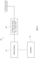
- System 400 can include processor(s) 410, communication circuitry 420, and memory 430.
- Processor(s) 410 can comprise processing circuitry and associated interface(s) (e.g., a communication interface (e.g., RF circuitry interface 316) for communicating with communication circuitry 420, a memory interface (e.g., memory interface 312) for communicating with memory 430, etc.).
- processing circuitry and associated interface(s) e.g., a communication interface (e.g., RF circuitry interface 316) for communicating with communication circuitry 420, a memory interface (e.g., memory interface 312) for communicating with memory 430, etc.).
- Communication circuitry 420 can comprise, for example circuitry for wired and/or wireless connection(s) (e.g., 206 and/or 208), which can include transmitter circuitry (e.g., associated with one or more transmit chains) and/or receiver circuitry (e.g., associated with one or more receive chains), wherein transmitter circuitry and receiver circuitry can employ common and/or distinct circuit elements, or a combination thereof).
- transmitter circuitry e.g., associated with one or more transmit chains
- receiver circuitry e.g., associated with one or more receive chains
- Memory 430 can comprise one or more memory devices (e.g., memory 204G, local memory (e.g., including CPU register(s)) of processor(s) discussed herein, etc.) which can be of any of a variety of storage mediums (e.g., volatile and/or non-volatile according to any of a variety of technologies/constructions, etc.), and can store instructions and/or data associated with one or more of processor(s) 410 or transceiver circuitry 420).
- memory devices e.g., memory 204G, local memory (e.g., including CPU register(s)) of processor(s) discussed herein, etc.) which can be of any of a variety of storage mediums (e.g., volatile and/or non-volatile according to any of a variety of technologies/constructions, etc.), and can store instructions and/or data associated with one or more of processor(s) 410 or transceiver circuitry 420).
- system 400 e.g., UE embodiments
- subscripts e.g., system 400 UE comprising processor(s) 410 UE , communication circuitry 420 UE , and memory 430 UE ).
- BS embodiments e.g., system 400 gNB
- network component e.g., UPF (User Plane Function), etc.
- UPF User Plane Function
- processor(s) 410 gNB etc.
- communication circuitry e.g., 420 gNB , etc.
- memory e.g., 430 gNB , etc.
- signaling or messaging between different embodiments of system 400 can be generated by processor(s) 410 1 , transmitted by communication circuitry 420 1 over a suitable interface or reference point (e.g., a 3GPP air interface, N3, N4, etc.), received by communication circuitry 420 2 , and processed by processor(s) 410 2 .
- a suitable interface or reference point e.g., a 3GPP air interface, N3, N4, etc.
- additional components e.g., antenna(s), network port(s), etc. associated with system(s) 400 1 and 400 2
- additional components e.g., antenna(s), network port(s), etc. associated with system(s) 400 1 and 400 2
- signals and/or messages can be generated and output for transmission, and/or transmitted messages can be received and processed.
- outputting for transmission can comprise one or more of the following: generating a set of associated bits that indicate the content of the signal or message, coding (e.g., which can include adding a cyclic redundancy check (CRC) and/or coding via one or more of turbo code, low density parity-check (LDPC) code, tailbiting convolution code (TBCC), etc.), scrambling (e.g., based on a scrambling seed), modulating (e.g., via one of binary phase shift keying (BPSK), quadrature phase shift keying (QPSK), or some form of quadrature amplitude modulation (QAM), etc.), and/or resource mapping to one or more Resource Elements (REs) (e.g., a scheduled set of resources, a set
- REs Resource Elements
- processing can comprise one or more of: identifying physical resources associated with the signal/message, detecting the signal/message, resource element group deinterleaving, demodulation, descrambling, and/or decoding.
- one or more of information can be configured to a UE via signaling (e.g., associated with one or more layers, such as L1 signaling or higher layer signaling (e.g., MAC, RRC, etc.)) from a gNB or other access point (e.g., via signaling generated by processor(s) 410 gNB , transmitted by communication circuitry 420 gNB , received by communication circuitry 420 UE , and processed by processor(s) 410 UE ).
- signaling e.g., associated with one or more layers, such as L1 signaling or higher layer signaling (e.g., MAC, RRC, etc.)
- a gNB or other access point e.g., via signaling generated by processor(s) 410 gNB , transmitted by communication circuitry 420 gNB , received by communication circuitry 420 UE , and processed by processor(s) 410 UE ).
- the type of signaling employed and/or the exact details of the operations performed at the UE and/or gNB in processing can vary. However, for convenience, such operations can be referred to herein as configuring information/feature(s)/parameter(s)/etc. to a UE, generating or processing configuration signaling, or via similar terminology.
- a UE in DRX mode can operate (e.g., via a Medium Access Control (MAC) entity of the UE, e.g., as implemented by processors 410 UE , etc.) according to a DRX cycle (e.g., the long DRX cycle or the short DRX cycle) that can allow for discontinuous monitoring of PDCCH, etc., which can provide for reduced power consumption.
- MAC Medium Access Control
- DRX operation can be controlled and/or configured via Radio Resource Control (RRC) by configuring a number of parameters associated with DRX operation (e.g., via RRC signaling generated by processor(s) 410 gNB , transmitted by communication circuitry 420 gNB , received by communication circuitry 420 UE , and processed by processor(s) 410 UE ).
- RRC Radio Resource Control
- These parameters can comprise parameters related to: a DRX on duration timer (e.g., via the drx-onDurationTimer parameter), a DRX inactivity timer (e.g., via the drx-Inactivity Timer ), start of a DRX cycle (e.g., via the drx-LongCycleStartOffset ), optional parameters related to a short DRX cycle (e.g., drx-ShortCycle and drx-ShortCycleTimer ).
- a DRX on duration timer e.g., via the drx-onDurationTimer parameter
- a DRX inactivity timer e.g., via the drx-Inactivity Timer
- start of a DRX cycle e.g., via the drx-LongCycleStartOffset
- optional parameters related to a short DRX cycle e.g., drx-S
- Various embodiments can relate to operations (e.g., by a UE and/or gNB) during a DRX cycle (e.g., long or short), including but not limited to operations during and/or prior to a DRX on duration, and operations related to actions taken in connection with the DRX on duration timer and/or DRX inactivity timer.
- the first set of techniques comprise techniques related to transmission of a Scheduling Request (SR) by a UE (e.g., employing a system 400 UE , etc.) operating in DRX mode relative to one or more cells (e.g., a Primary Cell (PCell), and optionally a Primary Secondary Cell (PSCell), alone, or in addition to one or more other SCells) from one or more gNBs (e.g., employing a system 400 gNB , etc.).
- SR Scheduling Request
- PCell Primary Cell
- PSCell Primary Secondary Cell
- a UE e.g., that has UL data to transmit for which the UE does not yet have an associated Physical Uplink Shared Channel (PUSCH) grant
- PUSCH Physical Uplink Shared Channel
- a SR e.g., generated by processor(s) 410 UE , transmitted by communication circuitry 420 UE , received by communication circuitry 420 gNB , and processed by processor(s) 410 gNB
- a SR e.g., generated by processor(s) 410 UE , transmitted by communication circuitry 420 UE , received by communication circuitry 420 gNB , and processed by processor(s) 410 gNB
- a selected beam during a DRX on duration of a DRX cycle e.g., long or short
- the selected beam can be a best beam of one or more candidate beams, which can be determined as discussed herein, based on one or more of Channel State Information Reference Signal(s) (CSI-RS) and/or Synchronization Signal Block(s) (SSB(s)) transmitted by the gNB (e.g., generated by processor(s) 410 gNB , transmitted by communication circuitry 420 gNB , received by communication circuitry 420 UE , and processed by processor(s) 410 UE ).
- CSI-RS Channel State Information Reference Signal
- SSB(s) Synchronization Signal Block
- the selected beam can be a previously employed beam, which can have been, for example, previously determined (e.g., during or prior to an earlier DRX on duration) to be a best beam (e.g., as discussed herein).
- SSB and/or CSI-RS can be configured for the UE for each DRX on duration (or each N DRX on durations, wherein N is a positive integer; e.g., some embodiments can have N > 1, such as in connection with a short DRX cycle, etc.) for each of a plurality of beams for the UE to check beam quality of those beams. For one or more of these beams (e.g.
- the SSB and/or CSI-RS can be during the DRX on duration, while in other embodiments they can be outside the DRX on duration of the UE. In various embodiments wherein the SSB and/or CSI-RS are outside the DRX on duration of the UE, they can be configured immediately prior to (e.g., in one or more slot(s) immediately prior to) the start of the DRX on duration of the UE, which can minimize power consumption at the UE.
- one or more sets of PUCCH resources can be configured to the UE for transmission of the SR, and each of the configured PUCCH resources can have a fixed mapping to one or more of the SSB and/or CSI-RS (and, equivalently, to the one or more gNB beams over which those one or more SSB and/or CSI-RS were transmitted).
- the UE can determine (e.g., via processor(s) 410 UE ) from that beam selection which PUCCH resources to employ for SR transmission.
- a previously selected beam can be associated with configured dedicated PUCCH resources for that previously selected beam (e.g., in embodiments employing one-to-one mapping, or in embodiments employing many-to-one mapping for one or more PUCCH resources). This can further minimize UE power consumption, giving the option for the UE to omit SSB/CSI-RS measurement, or SSB/CSI-RS measurement for other beams (e.g., while still measuring the previously selected beam to determine if its beam quality metric is sufficient).
- each of the multiple PUCCH can be associated with a distinct beam of the plurality of beams.
- the UE e.g., via processor(s) 410 UE
- the UE can determine the associated PUCCH resources.
- the mapping of PUCCH resources to SSB/CSI-RS can be previously configured for the UE at some time prior to transmission of the SSB/CSI-RS (e.g., prior to the DRX on duration, etc.).
- these dedicated PUCCH resources can also be previously configured (e.g., at the same time).
- a threshold can be configured for the associated beam quality metric such that transmission of the SR by the UE can depend on the beam selected by the UE (e.g., best beam, a previously selected beam, a first qualifying beam, etc.) having an associated beam quality metric greater than or equal to the configured threshold, which can thereby reduce latency.
- the UE can optionally omit later measurements once at least one beam has been found to have an associated beam quality metric that meets the threshold, which can reduce power consumption.
- UE pathloss estimates are determined from the Reference Signal(s) (RS(s)) or Synchronization Signal(s) (SS(s)) used for detecting the selected (e.g., best) beam and the receive beam used for receiving the selected beam.
- RS(s) Reference Signal(s)
- SS(s) Synchronization Signal(s)
- a minimum number of samples or measurement duration(s) can be configured for the UE, in order to ensure the UE can obtain a reliable path loss estimate for power control.
- CSI-RS 502 i transmitted in a TDM manner (e.g., with each distinct set of CSI-RS transmitted a different time) from a gNB to a UE (e.g., wherein the CSI-RS (which could also be SSB in other scenarios) is generated by processor(s) 410 gNB , transmitted by communication circuitry 420 gNB , received by communication circuitry 420 UE , and processed by processor(s) 410 UE ) over a plurality of beam pairs 504 i (each comprising a gNB beam used for CSI-RS transmit (Tx) and a UE beam used for CSI-RS receive (Rx)).
- Tx gNB beam used for CSI-RS transmit
- Rx UE beam used for CSI-RS receive
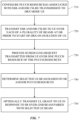
- a machine readable medium can store instructions associated with method 600 that, when executed, can cause a UE (e.g., employing system 400 UE ) to perform the acts of method 600.
- an associated beam quality metric (e.g., RSRP, RSRQ, SINR, etc.) can be measured for each beam of one or more beams based on signaling (e.g., SSB and/or CSI-RS) transmitted over that beam.
- the signaling can be transmitted during a DRX on duration of the UE or before (e.g., immediately prior to) the DRX on duration of the UE.
- a PUCCH resource associated with the selected (e.g., best) beam can be selected from multiple PUCCH resources for a SR transmission (e.g., a PUCCH resource uniquely associated with the selected beam, or associated with the selected beam and one or more other beams).
- a many-to-one mapping can be employed which may provide a single PUCCH resource rendering this selection unnecessary.
- the SR can be transmitted over the selected (e.g, best) beam during the DRX on duration of the UE.
- transmission of the SR over the selected (e.g., best) beam can depend on the associated beam quality metric for the selected (e.g., best) beam meeting or exceeding a threshold.
- the transmit power for the SR can be based on an estimated pathloss for the selected beam if there is sufficient information to measure that pathloss. If there is not, in some embodiments, a previously estimated pathloss for that beam can be used for transmit power determination. In other embodiments, if a first choice for selected beam does not have sufficient information to determine pathloss, a different beam can be selected at 620 for which sufficient information is available.
- one or more of PDCCH/PDSCH can be monitored/received and/or PUCCH/PUSCH can be transmitted over the selected beam used for SR transmission.
- This can include, for example, monitoring according to an active time of the UE (e.g., based on DRX on duration and/or inactivity duration timer(s)), such as for DCI indicating a UL grant in response to the SR, transmitting PUSCH via a UL grant, etc.
- method 600 can include one or more other acts described herein in connection with various embodiments of a UE and/or system 400 UE and the first set of techniques.
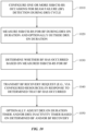
- a machine readable medium can store instructions associated with method 700 that, when executed, can cause a gNB (e.g., employing system 400 gNB ) to perform the acts of method 700.
- a gNB e.g., employing system 400 gNB
- one or more PUCCH resources can be configured to a UE that can be used to generate a SR.
- the PUCCH resources can be associated in a one-to-one or many-to-one with as plurality of SSB and/or CSI-RS to be transmitted to the UE for beam selection.
- a scheduling request can be received from the UE requesting a UL grant.
- the scheduling request can be transmitted over a selected beam of the UE for further communication (e.g., PDCCH/PDSCH/PUCCH/PUSCH, etc.).
- the PUCCH resource employed for transmission of the beam can be associated with one or more of the SSB and/or CSI-RS transmitted at 720.
- the selected beam of the UE can be determined based on the SR and/or PUCCH resource.
- a UL grant can be transmitted to the UE in response to the SR over a gNB beam corresponding to the selected beam of the UE, allocating PUSCH resources for UL data.
- method 700 can include one or more other acts described herein in connection with various embodiments of a gNB and/or system 400 gNB and the first set of techniques.
- the second set of techniques comprise techniques related to beam failure detection and recovery by a UE operating in DRX mode relative to one or more cells (e.g., a PCell, and optionally a PSCell, alone, or in addition to one or more other SCells) from one or more gNBs (e.g., employing a system 400 gNB , etc.).
- each beam can be handled separately, whereby techniques discussed herein can be separately applied by a UE and/or gNB in connection with one or more beams.
- signaling can be configured for a UE to detect beam failure (BF) on a given beam during a DRX cycle (e.g., long or short) of that UE.
- the signaling configured for BF can be comprise signaling within a DRX on duration of the UE.
- the signaling configured for BF can also comprise signaling outside of the DRX on duration of the UE.
- the UE can measure the signaling for BF during the DRX on duration, and can optionally measure none, some, or all of the signaling for BF outside the DRX on duration (e.g., wherein more measurements can provide more accurate determination, but increased power consumption), which can depend on UE ability to meet a minimum performance level for the beam.
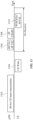
- FIG. 8 illustrated is an example timing diagram showing a plurality of CSI-RS and/or SSB 802 i configured for BF detection by a DRX mode UE, according to various embodiments discussed herein. In the example scenario shown in FIG.
- four sets of signaling for BF detection/recovery 802 1 -802 4 are configured during each DRX cycle of the UE, one of which (802 1 ) is during the DRX on duration of the UE.
- the number of times signaling for BF is configured during a DRX cycle can be greater or fewer in various embodiments.
- UL resources can be configured that can be used for reporting beam failure by the UE (e.g., for transmission of a BF recovery request generated by processor(s) 410 UE , transmitted by communication circuitry 420 UE , received by communication circuitry 420 gNB , and processed by processor(s) 410 gNB ).
- the nature of these resources can vary based on the type of cell associated with the given beam. For example, for a PCell or PSCell, contention based Physical Random Access Channel (PRACH) or contention free PRACH can be configured for the UE to report BF.
- PRACH Physical Random Access Channel
- PRACH contention free PRACH
- distinct PRACH can be configured for each beam in a one-to-one manner, while in other embodiments, a many-to-one mapping can be employed, which can be, for example, the same mapping employed between SSB/CSI-RS and PUCCH as discussed above in connection with the first set of techniques (e.g., related to candidate beam detection and selection).
- the configured resources for BF reporting and/or recovery can comprise PUCCH/SR resources, or can comprise a UL PUSCH grant.
- the operation of one or more DRX timers can be affected. For example, in various embodiments, if beam failure is detected, the DRX on duration timer and/or DRX inactivity timer can be stopped if active. In various embodiments, the one or more DRX timers can be paused when BF is detected and a BF recovery request is going to be transmitted. Additionally, in some embodiments, the one or more DRX timers can optionally also be reset to 0 (in others, they can be maintained paused at a current value).
- the one or more DRX timers can remain stopped.
- the UE can restart and/or reset (e.g., via processor(s) 410 UE ) the one or more DRX timers (e.g., DRX on duration timer, DRX inactivity timer).
- signaling for BF detection can be transmitted by the gNB (which, in various embodiments, can be prior to signaling 502 i for candidate beam selection, discussed in connection with the first set of techniques, above).
- the UE can pause an active DRX on duration timer (e.g., pause at a current value), or can alternatively reset the DRX on duration timer to 0 (as noted at the bottom of FIG. 9 ).
- the UE can transmit a BF recovery request, and can keep the DRX on duration timer stopped until the UE receives a response to the BF recovery request at 906, at which point the UE can restart the DRX on duration timer.
- the at least one DRX timer (e.g., DRX on duration timer, etc.) can be expired, and the UE can enter a sleep state. In such a situation, the UE can wake up on the next DRX on duration and attempt BF recovery again.
Landscapes
- Engineering & Computer Science (AREA)
- Signal Processing (AREA)
- Computer Networks & Wireless Communication (AREA)
- Quality & Reliability (AREA)
- Physics & Mathematics (AREA)
- Electromagnetism (AREA)
- Mobile Radio Communication Systems (AREA)
- Radio Relay Systems (AREA)
- Vehicle Body Suspensions (AREA)
- Toys (AREA)
Priority Applications (1)
| Application Number | Priority Date | Filing Date | Title |
|---|---|---|---|
| EP24211900.6A EP4482227A3 (de) | 2020-02-12 | 2020-02-12 | Strahlverwaltungsverbesserung für betrieb mit diskontinuierlichem empfang (drx) |
Applications Claiming Priority (3)
| Application Number | Priority Date | Filing Date | Title |
|---|---|---|---|
| EP24211900.6A EP4482227A3 (de) | 2020-02-12 | 2020-02-12 | Strahlverwaltungsverbesserung für betrieb mit diskontinuierlichem empfang (drx) |
| EP20918419.1A EP4046416A4 (de) | 2020-02-12 | 2020-02-12 | Strahlverwaltungsverbesserung für betrieb mit diskontinuierlichem empfang (drx) |
| PCT/CN2020/074916 WO2021159326A1 (en) | 2020-02-12 | 2020-02-12 | Beam management enhancement for discontinuous reception (drx) operation |
Related Parent Applications (1)
| Application Number | Title | Priority Date | Filing Date |
|---|---|---|---|
| EP20918419.1A Division EP4046416A4 (de) | 2020-02-12 | 2020-02-12 | Strahlverwaltungsverbesserung für betrieb mit diskontinuierlichem empfang (drx) |
Publications (2)
| Publication Number | Publication Date |
|---|---|
| EP4482227A2 true EP4482227A2 (de) | 2024-12-25 |
| EP4482227A3 EP4482227A3 (de) | 2025-03-05 |
Family
ID=77291985
Family Applications (2)
| Application Number | Title | Priority Date | Filing Date |
|---|---|---|---|
| EP24211900.6A Pending EP4482227A3 (de) | 2020-02-12 | 2020-02-12 | Strahlverwaltungsverbesserung für betrieb mit diskontinuierlichem empfang (drx) |
| EP20918419.1A Pending EP4046416A4 (de) | 2020-02-12 | 2020-02-12 | Strahlverwaltungsverbesserung für betrieb mit diskontinuierlichem empfang (drx) |
Family Applications After (1)
| Application Number | Title | Priority Date | Filing Date |
|---|---|---|---|
| EP20918419.1A Pending EP4046416A4 (de) | 2020-02-12 | 2020-02-12 | Strahlverwaltungsverbesserung für betrieb mit diskontinuierlichem empfang (drx) |
Country Status (6)
| Country | Link |
|---|---|
| US (2) | US12069708B2 (de) |
| EP (2) | EP4482227A3 (de) |
| JP (2) | JP7516531B2 (de) |
| KR (2) | KR102845213B1 (de) |
| CN (3) | CN118714666A (de) |
| WO (1) | WO2021159326A1 (de) |
Families Citing this family (10)
| Publication number | Priority date | Publication date | Assignee | Title |
|---|---|---|---|---|
| KR20240170591A (ko) * | 2019-02-14 | 2024-12-03 | 애플 인크. | 뉴 라디오(nr)에서의 2차 셀 빔 실패 복구 동작 |
| WO2022027254A1 (en) * | 2020-08-04 | 2022-02-10 | Apple Inc. | Cross-cell beam failure recovery |
| KR20220021049A (ko) * | 2020-08-12 | 2022-02-22 | 삼성전자주식회사 | 페이징 메시지를 수신하는 전자 장치 및 그 동작 방법 |
| WO2022036498A1 (en) * | 2020-08-17 | 2022-02-24 | Qualcomm Incorporated | Beam management for a secondary cell group in a dormant state |
| WO2022205196A1 (en) * | 2021-03-31 | 2022-10-06 | Apple Inc. | Reference cell timing determination |
| CN118120293A (zh) * | 2021-12-28 | 2024-05-31 | Oppo广东移动通信有限公司 | 通信方法、装置、终端、芯片、存储介质、产品及程序 |
| US12445961B2 (en) * | 2022-03-30 | 2025-10-14 | Qualcomm Incorporated | Beam failure detection reference signal monitoring for discontinuous reception |
| US12261668B2 (en) * | 2022-03-31 | 2025-03-25 | Qualcomm Incorporated | Enhanced UE behavior for BFD/BFR in DRX mode |
| CN117479273A (zh) * | 2022-07-22 | 2024-01-30 | 维沃移动通信有限公司 | 唤醒信号的发送和反馈方法、设备及可读存储介质 |
| US12375963B2 (en) * | 2022-07-26 | 2025-07-29 | Qualcomm Incorporated | Perception-aided beam-based communications |
Family Cites Families (21)
| Publication number | Priority date | Publication date | Assignee | Title |
|---|---|---|---|---|
| JP3001484B2 (ja) * | 1997-11-03 | 2000-01-24 | 静岡日本電気株式会社 | 無線選択呼出受信機及びチャネル選択方法 |
| CN103686781B (zh) | 2012-09-17 | 2018-07-17 | 中兴通讯股份有限公司 | Csi-rsrp测量周期的配置方法及终端 |
| KR102071372B1 (ko) * | 2013-09-16 | 2020-01-30 | 삼성전자 주식회사 | 무선 통신 시스템에서 빔 포밍을 고려한 drx 제어 방법 및 장치 |
| US10224994B2 (en) * | 2016-02-26 | 2019-03-05 | Samsung Electronics Co., Ltd. | System and method of connected mode discontinuous operation in beamformed system |
| TWI644530B (zh) * | 2016-12-13 | 2018-12-11 | 華碩電腦股份有限公司 | 無線通訊系統中用於波束管理的方法和設備 |
| US10601492B2 (en) | 2017-01-05 | 2020-03-24 | Futurewei Technologies, Inc. | Device/UE-oriented beam recovery and maintenance mechanisms |
| EP3606257B1 (de) | 2017-03-22 | 2021-10-06 | LG Electronics Inc. | Verfahren und benutzergerät zur ausführung einer strahlwiedereherstellung |
| US20180287860A1 (en) | 2017-03-31 | 2018-10-04 | Futurewei Technologies, Inc. | System and Method for Communications Beam Recovery |
| CN109246743B (zh) | 2017-04-28 | 2021-10-15 | 华为技术有限公司 | 一种波束管理方法及终端设备、网络设备 |
| KR102609643B1 (ko) * | 2017-09-27 | 2023-12-05 | 한국전자통신연구원 | 통신 시스템에서 무선 자원 관리를 위한 방법 및 장치 |
| JP7027766B2 (ja) * | 2017-09-29 | 2022-03-02 | 日本電気株式会社 | 無線アクセスネットワークに関連する装置、及び方法 |
| US10772151B2 (en) * | 2018-01-05 | 2020-09-08 | Ofinno, Llc | Beam management in discontinuous reception |
| KR102472292B1 (ko) * | 2018-01-10 | 2022-11-30 | 삼성전자 주식회사 | 무선 통신 시스템에서 경쟁 및 비경쟁 기반 빔 실패 복구를 수행하는 방법 및 장치 |
| EP3776900B1 (de) | 2018-03-28 | 2021-08-11 | Telefonaktiebolaget LM Ericsson (publ) | Effiziente anzeige räumlicher beziehungen für ressourcen von physischem uplink-steuerkanal (pucch) |
| KR102546164B1 (ko) * | 2018-04-05 | 2023-06-22 | 삼성전자주식회사 | 무선 통신 시스템에서 빔 실패 복구를 위한 장치 및 방법 |
| CN110475276B (zh) | 2018-05-10 | 2023-11-07 | 夏普株式会社 | 用户设备中的链路评估方法及用户设备 |
| US12294437B2 (en) | 2018-07-02 | 2025-05-06 | Huawei Technologies Co., Ltd. | System and method for link recovery with discontinuous reception |
| CN114916049B (zh) * | 2018-07-13 | 2022-12-13 | 华为技术有限公司 | 在不连续传输操作中节能的系统和方法 |
| US11510274B2 (en) | 2018-07-27 | 2022-11-22 | Qualcomm Incorporated | Proactive wake-up beam management for connected mode discontinuous reception (C-DRX) operation |
| US11350418B2 (en) * | 2019-01-24 | 2022-05-31 | Samsung Electronics Co., Ltd. | Method and apparatus for channel measurement and reporting in coreset basis |
| CN110475326A (zh) * | 2019-08-23 | 2019-11-19 | 重庆邮电大学 | 一种支持波束搜索的动态非连续接收方法、装置以及系统 |
-
2020
- 2020-02-12 WO PCT/CN2020/074916 patent/WO2021159326A1/en not_active Ceased
- 2020-02-12 JP JP2022549055A patent/JP7516531B2/ja active Active
- 2020-02-12 CN CN202410908306.0A patent/CN118714666A/zh active Pending
- 2020-02-12 KR KR1020227028017A patent/KR102845213B1/ko active Active
- 2020-02-12 CN CN202311090330.XA patent/CN116980957A/zh active Pending
- 2020-02-12 CN CN202080077528.2A patent/CN114731525B/zh active Active
- 2020-02-12 EP EP24211900.6A patent/EP4482227A3/de active Pending
- 2020-02-12 EP EP20918419.1A patent/EP4046416A4/de active Pending
- 2020-02-12 KR KR1020247039338A patent/KR20240170980A/ko active Pending
- 2020-02-12 US US17/442,252 patent/US12069708B2/en active Active
-
2024
- 2024-03-04 JP JP2024032097A patent/JP7688187B2/ja active Active
- 2024-08-19 US US18/808,278 patent/US20250310983A1/en active Pending
Also Published As
| Publication number | Publication date |
|---|---|
| CN118714666A (zh) | 2024-09-27 |
| EP4046416A4 (de) | 2024-01-17 |
| WO2021159326A1 (en) | 2021-08-19 |
| JP7516531B2 (ja) | 2024-07-16 |
| US20220377756A1 (en) | 2022-11-24 |
| KR102845213B1 (ko) | 2025-08-12 |
| EP4482227A3 (de) | 2025-03-05 |
| JP2024073491A (ja) | 2024-05-29 |
| JP2023514262A (ja) | 2023-04-05 |
| KR20240170980A (ko) | 2024-12-05 |
| KR20220128403A (ko) | 2022-09-20 |
| JP7688187B2 (ja) | 2025-06-03 |
| EP4046416A1 (de) | 2022-08-24 |
| CN116980957A (zh) | 2023-10-31 |
| CN114731525A (zh) | 2022-07-08 |
| CN114731525B (zh) | 2024-07-19 |
| US12069708B2 (en) | 2024-08-20 |
| US20250310983A1 (en) | 2025-10-02 |
Similar Documents
| Publication | Publication Date | Title |
|---|---|---|
| US20250310983A1 (en) | Beam management enhancement for discontinuous reception (drx) operation | |
| US12052741B2 (en) | Methods of resource re-selection and pre-emption | |
| US20240380527A1 (en) | Method and apparatus for physical downlink shared channel (pdsch) hybrid automatic repeat request (harq)-acknowledgement (ack) feedback in wireless communication | |
| US12069571B2 (en) | Dual discontinuous reception (DRX) in frequency range 1 (FR1) and frequency range 2 (FR2) carrier aggregation (CA) | |
| EP4193532B1 (de) | Verfahren und vorrichtung für harq-feedback (ack)-feedback für semipersistent scheduling (sps)-freigabe eines physikalischen geteilten downlink-kanals (pdsch) | |
| US12483918B2 (en) | Sidelink feedback enhancement | |
| US11909532B2 (en) | Redundancy gap indication for improved data transmission | |
| US20230156849A1 (en) | Access control of user equipments for inactive direct transmissions | |
| US12200809B2 (en) | Method and apparatus for optimal user equipment (UE) power consumption in new radio (NR) connected discontinuous reception (C-DRX) mode | |
| US12213144B2 (en) | Uplink control information transmission in wireless communication | |
| US20230156571A1 (en) | Base station access control techniques for inactive direct transmission |
Legal Events
| Date | Code | Title | Description |
|---|---|---|---|
| PUAI | Public reference made under article 153(3) epc to a published international application that has entered the european phase |
Free format text: ORIGINAL CODE: 0009012 |
|
| STAA | Information on the status of an ep patent application or granted ep patent |
Free format text: STATUS: REQUEST FOR EXAMINATION WAS MADE |
|
| 17P | Request for examination filed |
Effective date: 20241108 |
|
| AC | Divisional application: reference to earlier application |
Ref document number: 4046416 Country of ref document: EP Kind code of ref document: P |
|
| AK | Designated contracting states |
Kind code of ref document: A2 Designated state(s): AL AT BE BG CH CY CZ DE DK EE ES FI FR GB GR HR HU IE IS IT LI LT LU LV MC MK MT NL NO PL PT RO RS SE SI SK SM TR |
|
| REG | Reference to a national code |
Ref country code: DE Ref legal event code: R079 Free format text: PREVIOUS MAIN CLASS: H04W0052240000 Ipc: H04W0024080000 |
|
| PUAL | Search report despatched |
Free format text: ORIGINAL CODE: 0009013 |
|
| AK | Designated contracting states |
Kind code of ref document: A3 Designated state(s): AL AT BE BG CH CY CZ DE DK EE ES FI FR GB GR HR HU IE IS IT LI LT LU LV MC MK MT NL NO PL PT RO RS SE SI SK SM TR |
|
| RIC1 | Information provided on ipc code assigned before grant |
Ipc: H04W 52/24 20090101ALI20250127BHEP Ipc: H04B 7/08 20060101ALI20250127BHEP Ipc: H04W 72/542 20230101ALI20250127BHEP Ipc: H04W 72/044 20230101ALI20250127BHEP Ipc: H04W 24/10 20090101ALI20250127BHEP Ipc: H04W 16/28 20090101ALI20250127BHEP Ipc: H04B 7/06 20060101ALI20250127BHEP Ipc: H04W 52/44 20090101ALI20250127BHEP Ipc: H04L 5/00 20060101ALI20250127BHEP Ipc: H04W 24/08 20090101AFI20250127BHEP |