EP4482076A2 - Frequenzsprungsteuerungsverfahren und -vorrichtung - Google Patents
Frequenzsprungsteuerungsverfahren und -vorrichtung Download PDFInfo
- Publication number
- EP4482076A2 EP4482076A2 EP24209343.3A EP24209343A EP4482076A2 EP 4482076 A2 EP4482076 A2 EP 4482076A2 EP 24209343 A EP24209343 A EP 24209343A EP 4482076 A2 EP4482076 A2 EP 4482076A2
- Authority
- EP
- European Patent Office
- Prior art keywords
- redcap
- frequency hopping
- hops
- present disclosure
- determining
- Prior art date
- Legal status (The legal status is an assumption and is not a legal conclusion. Google has not performed a legal analysis and makes no representation as to the accuracy of the status listed.)
- Pending
Links
Images




Classifications
-
- H—ELECTRICITY
- H04—ELECTRIC COMMUNICATION TECHNIQUE
- H04L—TRANSMISSION OF DIGITAL INFORMATION, e.g. TELEGRAPHIC COMMUNICATION
- H04L5/00—Arrangements affording multiple use of the transmission path
- H04L5/0001—Arrangements for dividing the transmission path
- H04L5/0003—Two-dimensional division
- H04L5/0005—Time-frequency
- H04L5/0007—Time-frequency the frequencies being orthogonal, e.g. OFDM(A) or DMT
- H04L5/0012—Hopping in multicarrier systems
-
- H—ELECTRICITY
- H04—ELECTRIC COMMUNICATION TECHNIQUE
- H04W—WIRELESS COMMUNICATION NETWORKS
- H04W72/00—Local resource management
- H04W72/04—Wireless resource allocation
- H04W72/044—Wireless resource allocation based on the type of the allocated resource
- H04W72/0457—Variable allocation of band or rate
-
- H—ELECTRICITY
- H04—ELECTRIC COMMUNICATION TECHNIQUE
- H04W—WIRELESS COMMUNICATION NETWORKS
- H04W8/00—Network data management
- H04W8/22—Processing or transfer of terminal data, e.g. status or physical capabilities
Definitions
- the present disclosure relates to the field of communication technologies, and in particular, to frequency hopping control methods and apparatuses.
- MTC Machine Type Communication
- NB-IoT Narrow Band Internet of things
- IoT Internet of things
- LTE Long Term Evolution
- 4G the 4th generation mobile communication technology
- redcap Reduced capability
- 5G the 5th generation mobile communication technology
- Embodiments of the present disclosure provide frequency hopping control methods and apparatuses for solving the above problem.
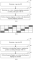
- An embodiment of a first aspect of the present disclosure proposes a frequency hopping control method, which is performed by a user equipment (UE), including: determining a type of a UE; determining one or more frequency hopping parameters according to the type of the UE; and performing frequency hopping according to the determined frequency hopping parameters.
- UE user equipment
- the frequency hopping parameter is a frequency hopping start position.
- the determining the frequency hopping start position according to the type of the UE includes: determining that the UE is a redcap UE, determining an initial position of a start frequency hopping of the UE; and determining the frequency hopping start position according to an initial value of the start frequency hopping.
- the determining the frequency hopping start position according to the initial position of the start frequency hopping includes: determining a system bandwidth of the UE; determining to the initial position of the start frequency hopping exceeding the system bandwidth of the UE, acquiring an adjustment value; and adjusting the initial position of the start frequency hopping according to the adjustment value to generate the frequency hopping start position.
- the adjustment value is determined by: a protocol; or, a signaling configuration sent by a base station.
- the determining the frequency hopping start position according to the type of the UE includes: acquiring a current number of hops; generating a current frequency hopping start position according to the current number of hops; generating an adjustment coefficient according to the type of the UE; and generating the frequency hopping start position according to the adjustment coefficient and the current frequency hopping start position.
- the generating the adjustment coefficient according to the type of the UE includes: if the UE is a non-redcap UE, acquire a bandwidth part (BWP) of the non-redcap UE and generating the adjustment coefficient according to the BWP; or if the UE is a redcap UE, acquiring a system bandwidth of the redcap UE and generating the adjustment coefficient according to the system bandwidth.
- BWP bandwidth part
- the generating the adjustment coefficient according to the system bandwidth includes: generating the adjustment coefficient according to a minimum value between the system bandwidth of the redcap UE and the BWP of the non-redcap UE.
- the generating the adjustment coefficient according to the type of the UE includes: generating the adjustment coefficient according to a minimum value between a BWP of a non-redcap UE and a system bandwidth of a redcap UE, where frequency hopping start positions of the non-redcap UE and the redcap UE are both generated by the adjustment coefficient.
- the determining the frequency hopping offset according to the type of the UE includes: acquiring an offset configuration table corresponding to the type of the UE; acquiring an offset identification indicated by a base station; and determining the frequency hopping offset according to the offset identification and the offset configuration table corresponding to the type of the UE.
- the frequency hopping offsets in the second offset configuration table are determined according to a minimum value between the system bandwidth of the redcap UE and the BWP of the non-redcap UE.
- both the non-redcap UE and the redcap UE can use the second offset configuration table.
- frequency hopping offsets corresponding to a non-redcap UE are determined by a BWP of the non-redcap UE, or frequency hopping offsets corresponding to a redcap UE are determined by a minimum value between the BWP of the non-redcap UE and a system bandwidth of the redcap UE.
- the one or more frequency hopping parameters include a number of hops.
- the number of hops supported by the non-redcap UE is greater than the number of hops supported by the redcap UE.
- the determining the number of hops according to the type of the UE includes: if the UE is a non-redcap UE, taking a first number of hops as the number of hops of the non-redcap UE; or if the UE is a redcap UE, taking a second number of hops as the number of hops of the redcap UE, where the first number of hops is greater than the second number of hops.
- the first number of hops and the second number of hops are configured by a protocol or indicated by a base station.
- the first number of hops and second number of hops are indicated by a remaining minimum system information (RMSI), random access response (RAR), or downlink control information (DCI) from the base station.
- RMSI remaining minimum system information
- RAR random access response
- DCI downlink control information
- the determining the number of hops according to the type of the UE includes: determining whether a BWP of a non-redcap UE is greater than a system bandwidth of a redcap UE; if greater than the system bandwidth of the redcap UE, taking a first preset number as a number of hops of the non-redcap UE, and taking a second preset number as a number of hops of the redcap UE, where the first preset number of hops is greater than the second preset number of hops; and if less than or equal to a system bandwidth of the redcap UE, taking the first preset number as the number of hops of the non-redcap UE and the redcap UE.
- the determining the number of hops according to the type of the UE includes: receiving a first indication number and a second indication number indicated by the base station, where the first indication number is greater than the second indication number; if a BWP of a non-redcap UE is greater than a system bandwidth of a redcap UE, taking the first indication number as a number of hops of the non-redcap UE, and taking the second indication number as a number of hops of the redcap UE.
- the determining the number of hops according to the type of the UE includes: receiving a third indication number indicated by the base station; if a first BWP of the non-redcap UE is less than or equal to a second BWP of the redcap UE, taking the third indication number as a number of hops of the non-redcap UE and the redcap UE.
- the first indication number and second indication number, or third indication number are indicated by an RMSI, an RAR, or a DCI from the base station.
- the number of hops corresponding to the non-redcap UE is indicated by the base station, or the number of hops corresponding to the redcap UE is specified by a protocol.
- An embodiment of a second aspect of the present disclosure proposes a frequency hopping control method, which is performed by a redcap UE, including: confirming a position of a next hop of the redcap UE; if a frequency domain position of the next hop exceeds a frequency domain position where a current operating bandwidth of the redcap is located, performing radio frequency (RF) retuning, such that an operating bandwidth of the redcap UE hops to a frequency domain position where the next hop is located.
- RF radio frequency
- a time interval for radio frequency retuning is specified by a protocol as a fixed value, or indicated by a base station.
- the time interval is indicated by a system message, a media access control control element (MAC CE), or downlink control information (DCI) signaling.
- MAC CE media access control control element
- DCI downlink control information
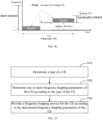
- An embodiment of a third aspect of the present disclosure proposes a frequency hopping control method, which is performed by a base station, including: determining a type of a UE; determining one or more frequency hopping parameters of the UE according to the type of the UE; and providing a frequency hopping service for the UE according to the determined frequency hopping parameters of the UE.
- the frequency hopping parameter is a frequency hopping start position.
- the determining the frequency hopping start position of the UE according to the type of the UE includes: determining that the UE is a redcap UE, determining an initial position of a start frequency hopping of the UE; and determining the frequency hopping start position according to an initial value of the start frequency hopping.
- the determining the frequency hopping start position of the UE according to the initial position of the start frequency hopping includes: determining a system bandwidth of the UE; determining the initial position of the start frequency hopping exceeding the system bandwidth of the UE, acquiring an adjustment value; and adjusting the initial position of the start frequency hopping according to the adjustment value to generate the frequency hopping start position.
- the adjustment value is determined by: a protocol; or, sending signaling to the UE for configuration.
- the determining the frequency hopping start position of the UE according to the type of the UE includes: acquiring a current number of hops of the UE; generating a current frequency hopping start position of the UE according to the current number of hops; generating an adjustment coefficient according to the type of the UE; and generating the frequency hopping start position of the UE according to the adjustment coefficient and the current frequency hopping start position.
- the generating the adjustment coefficient according to the type of the UE includes: if the UE is a non-redcap UE, acquire a bandwidth part (BWP) of the non-redcap UE and generating the adjustment coefficient according to the BWP; and if the UE is a redcap UE, acquiring a system bandwidth of the redcap UE and generating the adjustment coefficient according to the system bandwidth.
- BWP bandwidth part
- the generating the adjustment coefficient according to the system bandwidth includes: generating the adjustment coefficient according to a minimum value between the system bandwidth of the redcap UE and the BWP of the non-redcap UE.
- the generating the adjustment coefficient according to the type of the UE includes: generating the adjustment coefficient according to a minimum value between a BWP of a non-redcap UE and a system bandwidth of a redcap UE, where frequency hopping start positions of the non-redcap UE and the redcap UE are both generated by the adjustment coefficient.
- the one or more frequency hopping parameters are frequency hopping offsets.
- the determining the frequency hopping offsets of the UE according to the type of the UE includes: sending an offset configuration table corresponding to the type of the UE to the UE; and sending an offset identification to the UE.
- the UE further including: if the UE is a non-redcap UE, determining frequency hopping offsets in a first offset configuration table corresponding to the non-redcap UE according to a BWP of the non-redcap UE; and if the UE is a redcap UE, determining frequency hopping offsets in a second offset configuration table corresponding to the redcap UE according to a system bandwidth of the redcap UE.
- the frequency hopping offsets in the second offset configuration table are determined according to a minimum value between the system bandwidth of the redcap and the BWP of the non-redcap UE.
- the offset configuration table is determined by: a protocol; or, sending signaling to the UE for configuration.
- both the non-redcap UE and the redcap UE can use the second offset configuration table.
- frequency hopping offsets corresponding to a non-redcap UE are determined by a BWP of the non-redcap UE, and frequency hopping offsets corresponding to a redcap UE are determined by a minimum value between the BWP of the non-redcap UE and a system bandwidth of the redcap UE.
- the frequency hopping parameter is a number of hops.
- the number of hops supported by the non-redcap UE is greater than the number of hops supported by the redcap UE.
- the determining the number of hops of the UE according to the type of the UE includes: if the UE is a non-redcap UE, taking a first number of hops as the number of hops of the non-redcap UE; if the UE is a redcap UE, taking a second number of hops as the number of hops of the redcap UE, where the first number of hops is greater than the second number of hops.
- the first number of hops and the second number of hops are configured by a protocol or indicated by a base station.
- the first number of hops and second number of hops are indicated by remaining minimum system information (RMSI), random access response (RAR), or downlink control information (DCI) from the base station.
- RMSI remaining minimum system information
- RAR random access response
- DCI downlink control information
- the determining the number of hops of the UE according to the type of the UE includes: determining whether a BWP of a non-redcap UE is greater than a system bandwidth of a redcap UE; if greater than the system bandwidth of the redcap UE, taking a first preset number as a number of hops of the non-redcap UE, and taking a second preset number as a number of hops of the redcap UE, where the first preset number of hops is greater than the second preset number of hops; and if less than or equal to a system bandwidth of the redcap UE, taking the first preset number as the number of hops of the non-redcap UE and the redcap UE.
- the determining the number of hops of the UE according to the type of the UE includes: sending a first indication number and a second indication number, where the first indication number is greater than the second indication number; if a BWP of a non-redcap UE is greater than a system bandwidth of a redcap UE, taking the first indication number as a number of hops of the non-redcap UE, and taking the second indication number as a number of hops of the redcap UE.
- the determining the number of hops according to the type of the UE includes: sending a third indication number indicated by the base station; if a first BWP of the non-redcap UE is less than or equal to a second BWP of the redcap UE, taking the third indication number as a number of hops of the non-redcap UE and the redcap UE.
- the first indication number and second indication number, or third indication number are indicated by an RMSI, an RAR, or a DCI from the base station.
- the number of hops corresponding to the non-redcap UE is indicated by the base station, and the number of hops corresponding to the redcap UE is specified by a protocol.
- An embodiment of a fourth aspect of the present disclosure proposes a frequency hopping control apparatus, which is performed by a base station, including:
- the frequency hopping parameter is a frequency hopping start position.
- the second determining module is configured to: determining that the UE is a redcap UE, determine an initial position of a start frequency hopping of the UE; and determine the frequency hopping start position according to an initial value of the start frequency hopping.
- the second determining module is configured to: determine a system bandwidth of the UE; determining the initial position of the start frequency hopping exceeding the system bandwidth of the UE, acquire an adjustment value; and adjust the initial position of the start frequency hopping according to the adjustment value to generate the frequency hopping start position.
- the second determining module is configured to: determining the initial position of the start frequency hopping not exceeding the system bandwidth of the UE, determine the initial position of the start frequency hopping as the frequency hopping start position.
- the adjustment value is determined by: a protocol; or, a signaling configuration sent by a base station.
- the second determining module is configured to: determining the UEbeing a non-redcap UE, take the initial position of the start frequency hopping as the frequency hopping start position.
- the second determining module includes: a unit for acquiring a number of hops, configured to: acquire a current number of hops; a unit for generating a current frequency hopping start position, configured to: generate a current frequency hopping start position according to the current number of hops; a unit for generating an adjustment coefficient, configured to: generate an adjustment coefficient according to the type of the UE; and a unit for generating a frequency hopping start position, configured to: generate the frequency hopping start position according to the adjustment coefficient and the current frequency hopping start position.
- the unit for generating an adjustment coefficient is configured to: if the UE is a non-redcap UE, acquire a bandwidth part (BWP) of the non-redcap UE and generate the adjustment coefficient according to the BWP; and a subunit for acquiring a system bandwidth, configured to: if the UE is a redcap UE, acquire a system bandwidth of the redcap UE and generate the adjustment coefficient according to the system bandwidth.
- BWP bandwidth part
- the subunit for acquiring a system bandwidth is configured to: generate the adjustment coefficient according to a minimum value between the system bandwidth of the redcap UE and the BWP of the non-redcap UE.
- the unit for generating an adjustment coefficient is configured to: generate the adjustment coefficient according to a minimum value between a BWP of a non-redcap UE and a system bandwidth of a redcap UE, where frequency hopping start positions of the non-redcap UE and the redcap UE are both generated by the adjustment coefficient.
- the one or more frequency hopping parameters include a frequency hopping offset.
- the second determining module includes: a unit for acquiring an offset configuration table, configured to acquire an offset configuration table corresponding to the type of the UE; a unit for acquiring an offset identification unit, configured to acquire an offset identification indicated by the base station; and a unit for determining the frequency hopping offset, configured to determine frequency hopping offsets according to the offset identification and the offset configuration table corresponding to the type of the UE.
- a first frequency hopping offset unit configured to: if the UE is a non-redcap UE, determine frequency hopping offsets in a first offset configuration table corresponding to the non-redcap UE according to a BWP of the non-redcap UE; and a second frequency hopping offset unit, configured to: if the UE is a redcap UE, determine frequency hopping offsets in a second offset configuration table corresponding to the redcap UE according to a system bandwidth of the redcap UE.
- the frequency hopping offsets in the second offset configuration table are determined according to a minimum value between the system bandwidth of the redcap and the BWP of the non-redcap UE.
- both the non-redcap UE and the redcap UE can use the second offset configuration table.
- the frequency hopping parameter is a number of hops.
- the number of hops supported by the non-redcap UE is greater than the number of hops supported by the redcap UE.
- the first number of hops and the second number of hops are configured by a protocol or indicated by a base station.
- the first number of hops and second number of hops are indicated by a remaining minimum system information (RMSI), random access response (RAR), or downlink control information (DCI) from the base station.
- RMSI remaining minimum system information
- RAR random access response
- DCI downlink control information
- the second determining module includes: a first determining module, configured to determine whether a BWP of a non-redcap UE is greater than a system bandwidth of a redcap UE; a second for determining a number of hops of a non-redcap UE, configured to: if greater than the system bandwidth of the redcap UE, take a first preset number as a number of hops of the non-redcap UE, and take a second preset number as a number of hops of the redcap UE, where the first preset number of hops is greater than the second preset number of hops; and a first unit for determining a number of hops of a non-redcap UE and a redcap UE, configured to: if less than or equal to a system bandwidth of the redcap UE, take the first preset number as the number of hops of the non-redcap UE and the redcap UE.
- the second determining module includes: a first receiving indication number unit, configured to: receive a first indication number and a second indication number indicated by the base station, where the first indication number is greater than the second indication number; and a second unit for determining a number of hops of a non-redcap UE and a redcap UE, configured to: if a BWP of a non-redcap UE is greater than a system bandwidth of a redcap UE, take the first indication number as a number of hops of the non-redcap UE, and the second indication number as a number of hops of the redcap UE.
- the second determining module includes: a second receiving indication number unit, configured to: receive a third indication number indicated by the base station; and a third unit for determining a number of hops of a non-redcap UE and a redcap UE, configured to: if a first BWP of the non-redcap UE is less than or equal to a second BWP of the redcap UE, take the third indication number as a number of hops of the non-redcap UE and the redcap UE.
- the first indication number and second indication number, or third indication number are indicated by an RMSI, an RAR, or a DCI from the base station.
- the number of hops corresponding to the non-redcap UE is indicated by the base station, or the number of hops corresponding to the redcap UE is specified by a protocol.
- An embodiment of a fifth aspect of the present disclosure proposes a frequency hopping control apparatus, which is performed by a redcap UE, including: a third determining module, configured to confirm a position of a next hop of the redcap UE; a radio frequency retuning module, configured to perform radio frequency retuning if a frequency domain position of the next hop exceeds a frequency domain position where a current operating bandwidth of the redcap is located, such that an operating bandwidth of the redcap UE hops to a frequency domain position where the next hop is located.
- a time interval for radio frequency retuning is specified by a protocol as a fixed value, or indicated by a base station.
- the time interval is indicated by a system message, a media access control control element (MAC CE), or downlink control information (DCI) signaling.
- MAC CE media access control control element
- DCI downlink control information
- An embodiment of a sixth aspect of the present disclosure proposes a frequency hopping control apparatus, which is performed by a base station, including:
- the frequency hopping parameter is a frequency hopping start position.
- the fifth determining module is configured to: determining that the UE is a redcap UE, determine an initial position of a start frequency hopping of the UE; and determine the frequency hopping start position of the UE according to an initial value of the start frequency hopping of the UE.
- the fifth determining module is configured to: determine a system bandwidth of the UE; determining the initial position of the start frequency hopping exceeding the system bandwidth of the UE, acquire an adjustment value; and adjust the initial position of the start frequency hopping according to the adjustment value to generate the frequency hopping start position of the UE.
- the fifth determining module is configured to: determining the initial position of the start frequency hopping not exceeding the system bandwidth of the UE, determine the initial position of the start frequency hopping as the frequency hopping start position of the UE.
- the adjustment value is determined by: a protocol; or, sending signaling to the UE for configuration.
- the fifth determining module is configured to: determining the UE is a non-redcap UE, take the initial position of the start frequency hopping as the frequency hopping start position of the UE.
- the fifth determining module includes: a unit for acquiring a number of hops of the UE, configured to: acquire a current number of hops of the UE; a unit for generating a current frequency hopping start position of the UE, configured to generate a current frequency hopping start position of the UE according to the current number of hops; a generating unit, configured to: generate an adjustment coefficient according to the type of the UE; and a unit for generating a frequency hopping start position of the UE, configured to: generate the frequency hopping start position of the UE according to the adjustment coefficient and the current frequency hopping start position.
- the generating unit is configured to: if the UE is a non-redcap UE, acquire a bandwidth part (BWP) of the non-redcap UE and generate the adjustment coefficient according to the BWP; and if the UE is a redcap UE, acquire a system bandwidth of the redcap UE and generate the adjustment coefficient according to the system bandwidth.
- BWP bandwidth part
- the generating unit is configured to: generate the adjustment coefficient according to a minimum value between the system bandwidth of the redcap and the BWP of the non-redcap UE.
- the generating unit is configured to: generate the adjustment coefficient according to a minimum value between a BWP of a non-redcap UE and a system bandwidth of a redcap UE, where frequency hopping start positions of the non-redcap UE and the redcap UE are both generated by the adjustment coefficient.
- the one or more frequency hopping parameters include frequency hopping offsets.
- the fifth determining module includes: a first sending unit, configured to: send an offset configuration table corresponding to the type of the UE to the UE; and a second sending unit, configured to: send an offset identification to the UE.
- a unit for determining a first offset configuration table corresponding to a non-redcap UE configured to: if the UE is a non-redcap UE, determine frequency hopping offsets in a first offset configuration table corresponding to the non-redcap UE according to a BWP of the non-redcap UE; and a unit for determining a second offset configuration table corresponding to a UE, configured to: if the UE is a redcap UE, determine frequency hopping offsets in a second offset configuration table corresponding to the redcap UE according to a system bandwidth of the redcap UE.
- the frequency hopping offsets in the second offset configuration table are determined according to a minimum value between the system bandwidth of the redcap and the BWP of the non-redcap UE.
- the offset configuration table is determined by: a protocol; or, sending signaling to the UE for configuration.
- both the non-redcap UE and the redcap UE can use the second offset configuration table.
- frequency hopping offsets corresponding to a non-redcap UE are determined by a BWP of the non-redcap UE, and frequency hopping offsets corresponding to a redcap UE are determined by a minimum value between the BWP of the non-redcap UE and a system bandwidth of the redcap UE.
- the one or more frequency hopping parameters include a number of hops.
- the number of hops supported by the non-redcap UE is greater than the number of hops supported by the redcap UE.
- the fifth determining module includes: a third unit for determining a number of hops of a non-redcap UE, configured to: if the UE is a non-redcap UE, take a first number of hops as a number of hops of the non-redcap UE; and a second unit for determining a number of hops of a redcap UE, configured to: if the UE is a redcap UE, take a second number of hops as a number of hops of the redcap UE, where the first number of hops is greater than the second number of hops.
- the first number of hops and the second number of hops are configured by a protocol or indicated by a base station.
- the first number of hops and second number of hops are indicated by a remaining minimum system information (RMSI), random access response (RAR), or downlink control information (DCI) from the base station.
- RMSI remaining minimum system information
- RAR random access response
- DCI downlink control information
- the fifth determining module includes: a second determining module, configured to determine whether a BWP of a non-redcap UE is greater than a system bandwidth of a redcap UE; a fourth for determining a number of hops of a non-redcap UE, configured to: if greater than the system bandwidth of the redcap UE, take a first preset number as a number of hops of the non-redcap UE, and take a second preset number as a number of hops of the redcap UE, where the first preset number of hops is greater than the second preset number of hops; and a fourth unit for determining a number of hops of a non-redcap UE and a redcap UE, configured to: if less than or equal to a system bandwidth of the redcap UE, take the first preset number as the number of hops of the non-redcap UE and the redcap UE.
- the fifth determining module includes: a third sending unit, configured to: send a first indication number and a second indication number, where the first indication number is greater than the second indication number; where, if a BWP of a non-redcap UE is greater than a system bandwidth of a redcap UE, take the first indication number as a number of hops of the non-redcap UE, and take the second indication number as a number of hops of the redcap UE.
- the fifth determining module includes: a fourth sending unit, configured to: send a third indication number, where if a first BWP of the non-redcap UE is less than or equal to a second BWP of the redcap UE, taking the third indication number as a number of hops of the non-redcap UE and the redcap UE.
- the first indication number and second indication number, or third indication number are indicated by an RMSI, an RAR, or a DCI from the base station.
- the number of hops corresponding to the non-redcap UE is indicated by the base station, and the number of hops corresponding to the redcap UE is specified by a protocol.
- An embodiment of a seventh aspect of the present disclosure provides a communication device, including: a transceiver; a memory; a processor, connected to the transceiver and the memory, respectively, and configured to control radio signal transmission and reception of the transceiver by executing computer-executable instructions on the memory, and realize the frequency hopping control method proposed in the embodiment of the first aspect, the frequency hopping control method proposed in the second aspect or the frequency hopping control method proposed in the third aspect.
- An embodiment of an eighth aspect of the present disclosure proposes a processor-readable storage medium, which stores a computer program for causing the processor to execute the frequency hopping control method proposed in the embodiment of the first aspect, the frequency hopping control method proposed in the embodiment of the second aspect or the frequency hopping control method proposed in the third aspect.
- a frequency hopping control method and apparatus is provided by the embodiment of the present disclosure, which determines a type of a UE; determines one or more frequency hopping parameters according to the type of the UE; and performs frequency hopping according to the determined frequency hopping parameters. Therefore, the frequency hopping parameters can be adjusted according to the type of the UE, thereby avoiding a situation of hopping out of a system bandwidth range of a redcap UE.
- redcap UE because a system bandwidth of the redcap UE is small, when the redcap UE performs frequency hopping, it may cause the redcap UE to hop out of the system bandwidth and cannot work. Therefore, how to avoid a redcap UE from hopping out of system bandwidth during frequency hopping has become an urgent problem.
- embodiments of the present disclosure provide frequency hopping control methods and apparatuses.
- FIG. 1 is a schematic flowchart of a frequency hopping method according to an embodiment of the present disclosure; which is executed by a UE.
- a same initial uplink BWP bandwidth part
- non-redcap UE non-reduced capability UE
- frequency hopping parameters can be adjusted according to a type of UE to avoid the situation where the redcap UE hops out of its system bandwidth range.
- frequency hopping parameters include the frequency hopping offset value, the number of hops, the FH time domain granularity, and so on.
- the frequency hopping offset value is used to determine a start position of each hop; the number of hops is used to achieve a higher frequency diversity gain by configuring multiple frequency domain positions; and the FH time domain granularity is used to expand basic granularities of time-domain frequency hopping, which can support cross-slot joint channel estimation, or reduce DMRS (Demodulation Reference Signal) density for a low mobility or stationary UE.
- DMRS Demodulation Reference Signal
- the frequency hopping control method includes the following steps.
- a type of a UE is determined.
- the types of UE include a redcap (Reduced capability) UE and a non-redcap UE.
- the redcap UE can be understood as an IoT device with a smaller bandwidth or fewer antennas
- the non-redcap UE can be understood as a regular NR terminal that supports all the features of NR.
- MTC and NB-IoT two major technologies, MTC and NB-IoT, have been proposed to support IoT services. These two major technologies are mainly aimed at scenarios such as low rate and high latency, for example, meter reading and environmental monitoring.
- NB-IoT can only support rates of up to a few hundred kilobytes (k), while MTC can only support rates of up to a few megabytes (M).
- k k
- MTC megabytes
- this new type of UE is collectively referred to as a Reduced Capability UE, i.e., a redcap UE, while a current normal terminal is referred to as a non-redcap UE in the embodiment of the present disclosure.
- a redcap UE typically has the following features:
- a bandwidth of the redcap UE can be limited, for example, to 10 MHz or 20 MHz, or the number of receiving antennas for the redcap UE can be limited.
- a possible optimization direction is to reduce the processing complexity of user equipment, such as only receiving a PDCCH (Physical Downlink Control Channel) in a slot, and entering a micro-sleep state at other symbols in the same slot.
- PDCCH Physical Downlink Control Channel
- multiple repeated transmissions can be performed on each channel, reduce bit rates, etc.
- the type of the UE can be determined based on a size of a bandwidth.
- a base station can obtain a bandwidth of the UE, and the type of the UE can be determined according to a bandwidth size of the UE, that is, a redcap UE or a non-redcap UE.
- two types of UE can further be distinguished based on a physical random access channel (PRACH).
- PRACH physical random access channel
- the frequency hopping offset value is used to determine a start position of each hop.
- the number of hops can be understood as hop numbers in the frequency hopping: for example, if Message3 (msg3) is repeatedly transmitted 8 times, the FH time domain granularity is 1 slot, and the number of hops can be 4, a frequency hopping mode can be shown in FIG. 2 . That is to say, during a repetition process, the transmission of msg3 has 4 different frequency domain positions (as shown in the grey part of FIG. 2 ).
- one or more frequency hopping parameters are determined according to the type of the UE.
- the frequency hopping parameters include one or more of frequency hopping start position, frequency hopping offset, and a number of hops.
- the frequency hopping parameters are determined according to the type of the UE. Specifically, separate frequency hopping parameters can be set for the redcap UE and for the non-redcap UE.
- the redcap UE can set hopping parameters according to its own system bandwidth to avoid hopping out of the redcap system bandwidth during frequency hopping.
- same frequency hopping parameters can also be set for both the redcap UE and the non-redcap UE.
- the frequency hopping parameters need to take into account the redcap UE to avoid a situation that the redcap UE hops out of a system bandwidth range of the redcap UE. Or, it is possible to maintain current frequency hopping parameters of the non-redcap UE and adjust frequency hopping parameters of the redcap UE.
- one or more of the frequency hopping start position, the frequency hopping offset, and the number of hops can be adjusted to avoid the situation of hopping out of the system bandwidth range of the redcap UE.
- frequency hopping is performed according to the determined frequency hopping parameters.
- frequency hopping can be performed according to the frequency hopping parameters determined by the UE. For example, frequency hopping is performed according to the frequency hopping start position, the frequency hopping offset, and the number of hops.
- the frequency hopping parameters can be adjusted according to the type of the UE, thereby avoiding a situation of hopping out of a system bandwidth range of a redcap UE.
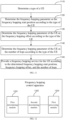
- FIG. 3 is a schematic flowchart of a frequency hopping method according to an embodiment of the present disclosure, which is executed by a UE. After determining parameters such as a frequency hopping offset value, a number of hops, and a FH time domain granularity, UE can perform frequency hopping according to the determined frequency hopping parameters. It should be noted that in the embodiment of the present disclosure, frequency hopping parameters include the frequency hopping offset value, the number of hops, the FH time domain granularity, and so on.
- the frequency hopping offset value is used to determine a start position of each hop; the number of hops is used to achieve higher frequency diversity gain by configuring multiple frequency domain positions; and the FH time domain granularity is used to expand basic granularities of time-domain frequency hopping, which can support cross-slot joint channel estimation, or reduce DMRS density for a low mobility or stationary UE.
- a frequency hopping parameter can be a frequency hopping start position.
- the frequency hopping control method includes the following steps: At step 301, a type of a UE is determined.
- the types of UE include a redcap UE and a non-redcap UE.
- the redcap UE can be understood as an IoT device with a smaller bandwidth or fewer antennas
- the non-redcap UE can be understood as a regular NR terminal that supports all the features of NR.
- a corresponding frequency hopping start position is determined according to the type of the UE.
- the frequency hopping start position can be determined in a same way for a non-redcap UE and a redcap UE.
- the redcap UE after determining the frequency hopping start position for the redcap UE, it may be necessary to adjust the frequency hopping start position for the redcap UE, thereby avoiding a situation of hopping out of a system bandwidth range of a redcap UE.
- the frequency hopping parameter can be determined as the frequency hopping start position by the following manner.
- determining that the UE is a redcap UE an initial position of a start frequency hopping of the redcap UE is determined at first, and then the frequency hopping start position is determined according to the initial position of the start frequency hopping.
- a corresponding adjustment value can be determined according to a system bandwidth of the redcap UE, and then the initial position of the frequency hopping can be adjusted according to the adjustment value, so as to determine the frequency hopping start position.
- the adjustment value is determined by: a protocol; or, a signaling configuration sent by a base station.
- the adjustment value can be fixed by a protocol or dynamically configured by the base station.
- the frequency hopping start position of the nth hop may be changed to a position b of a (n-m)th hop, where b is within the system bandwidth range of the redcap UE, and n>m.
- m can be fixed by a protocol or dynamically configured by the base station. m is determined based on the number of hops.
- FIG. 4 it is a schematic diagram of adjusting a frequency hopping start position according to an embodiment of the present disclosure.
- the adjustment value for example 2
- the adjustment value for example, 2
- determining the initial position of the start frequency hopping not exceeding the system bandwidth of the UE can be determined as the frequency hopping start position directly.
- the frequency hopping parameter can be determined as the frequency hopping start position by the following manner.
- determining the UE is a non-redcap UE the initial position of the start frequency hopping is taken as the frequency hopping start position.
- the base station can inform the UE of the adjustment value by sending signaling to the UE.
- the signaling may include remaining minimum system information (RMSI) signaling.
- step 303 frequency hopping is performed according to the frequency hopping start position.
- frequency hopping after determining the frequency hopping start position, frequency hopping can be performed according to the frequency hopping start position.
- the redcap UE its initial position of the frequency hopping is adjusted to determine the frequency hopping start position corresponding to the redcap UE, thereby avoiding hopping out of the system bandwidth range of a redcap UE.
- FIG. 5 is a schematic flowchart of a frequency hopping method according to an embodiment of the present disclosure; which is executed by a UE.
- UE After determining frequency parameters such as a frequency hopping offset value, the number of hops, and a FH time domain granularity, UE can perform frequency hopping according to the determined frequency hopping parameters.
- frequency hopping parameters include the frequency hopping offset value, the number of hops, and the FH time domain granularity and so on.
- the frequency hopping offset value is used to determine a start position of each hop; the number of hops is used to achieve higher frequency diversity gain by configuring multiple frequency domain positions; and the FH time domain granularity is used to expand basic granularities of time-domain frequency hopping, which can support cross-slot joint channel estimation, or reduce DMRS density for a low mobility or stationary UE.
- a corresponding formula for determining a frequency hopping start position can be set for a redcap UE, thereby avoiding a situation of hopping out of a system bandwidth range of the redcap UE.
- the frequency hopping control method includes the following steps.
- a type of a UE is determined.
- the types of UE include a redcap UE and a non-redcap UE.
- the redcap UE can be understood as an IoT device with a smaller bandwidth or fewer antennas
- the non-redcap UE can be understood as a regular NR terminal that supports all the features of NR.
- a current number of hops is acquired.
- a current frequency hopping start position is generated according to the current number of hops.
- i the current number of hops
- RBstart is the current frequency hopping start position
- RBoffset is an offset
- an adjustment coefficient is generated according to the type of the UE.
- a corresponding adjustment coefficient is generated according to the type of the UE, and the current frequency hopping start position can be adjusted by the adjustment coefficient.
- the adjustment coefficient is mod N BWP size , where N BWP size is a bandwidth part (BWP) of the non-redcap UE.
- the adjustment coefficient can be generated according to a system bandwidth of the redcap UE.
- the adjustment coefficient is mod min N BWP size N BW size , where N BWP size is a bandwidth part (BWP) of the non-redcap UE, and N BW size is a system bandwidth of the redcap UE.
- the adjustment coefficient generated based on the modulo operation may further be generated based in other manners, which is not limited by the present disclosure.
- the frequency hopping start position is generated according to the adjustment coefficient and the current frequency hopping start position.
- the current frequency hopping start position is adjusted by adjusting the adjustment coefficient, so as to generate the frequency hopping start position.
- step 506 frequency hopping is performed according to the frequency hopping start position.
- UE After UE determines its corresponding frequency hopping start position, it performs frequency hopping according to the determined frequency hopping start position.
- the adjustment coefficient can be determined based on the type of the UE, so that the redcap UE can avoid hopping out of the system bandwidth range of the redcap UE.
- frequency hopping start positions of the redcap UE and the non-redcap UE can be determined by the following manner.
- the frequency hopping start position can further be determined by the following formula.
- the frequency hopping start position can be determined by the following formula:
- redcap UE supports RF (Radio Frequency) retuning between RAR (Random Access Response) and Msg3.
- RF Radio Frequency
- the adjustment coefficient is generated according to a minimum value between the system bandwidth of the redcap UE and the BWP of the non-redcap UE.
- both the redcap UE and the non-redcap UE use a same formula for determining the frequency hopping start position.
- the base station since the formulas used for the redcap UE and the non-redcap UE are the same (both using the formula for determining the frequency hopping start position of the redcap UE as shown above), the base station does not need to distinguish between the redcap UE and the non-redcap UE.
- the adjustment coefficient is generated according to a minimum value between a BWP of a non-redcap UE and a system bandwidth of a redcap UE, where frequency hopping start positions of the non-redcap UE and the redcap UE are both generated by the adjustment coefficient.
- FIG. 6 is a schematic flowchart of a frequency hopping method according to an embodiment of the present disclosure; which is executed by a UE.
- UE After determining frequency parameters such as a frequency hopping offset value, the number of hops, and a FH time domain granularity, UE can perform frequency hopping according to the determined frequency hopping parameters.
- frequency hopping parameters include the frequency hopping offset value, the number of hops, and the FH time domain granularity.
- the frequency hopping offset value is used to determine a start position of each hop; the number of hops is used to achieve higher frequency diversity gain by configuring multiple frequency domain positions; and the FH time domain granularity is used to expand basic granularities of time-domain frequency hopping, which can support cross-slot joint channel estimation, or reduce DMRS density for a low mobility or stationary UE.
- the frequency hopping parameter may be a frequency hopping offset.
- a problem of hopping out of a system bandwidth of a redcap UE can also be avoided by adjusting the frequency hopping offset of the redcap UE.
- the frequency hopping control method includes the following steps: At step 601, a type of a UE is determined.
- the types of UE include a redcap UE and a non-redcap UE.
- the redcap UE can be understood as an IoT device with a smaller bandwidth or fewer antennas
- the non-redcap UE can be understood as a regular NR terminal that supports all the features of NR.
- the frequency hopping parameter is determined as the frequency hopping offset according to the type of the UE.
- an offset configuration table corresponding to the type of the UE can be acquired first; then an offset identification indicated by a base station can be acquired; and the frequency hopping offset can be determined according to the offset identification and the offset configuration table corresponding to the type of the UE.
- different offset configuration tables are set for different types of UE.
- the offset configuration table may be specified by a protocol or notified by the base station via a system message.
- a same offset configuration table can be configured for the non-redcap UE and the redcap UE, and different offset configuration tables can also be configured for the non-redcap UE and the redcap UE. If the same offset configuration table is configured, it is necessary to avoid the redcap UE hopping out of its own system bandwidth.
- step 603 frequency hopping is performed according to the frequency hopping offset.
- UE performs frequency hopping according to the frequency hopping offset determined in the above steps.
- the frequency hopping offset of the redcap UE can be adjusted to avoid a problem of the redcap UE hopping out of a system bandwidth range.
- frequency hopping offsets in a first offset configuration table corresponding to the non-redcap UE are determined according to a BWP of the non-redcap UE; and when the UE is a redcap UE, frequency hopping offsets in a second offset configuration table corresponding to the redcap UE are determined according to a system bandwidth of the redcap UE.
- the non-redcap UE can use the following first offset configuration table: Table 1 Number of PRBs for BWP Offset identification Offset N BWP size ⁇ 50 0 N BWP size / 2 1 N BWP size / 4 N BWP size ⁇ 50 00 N BWP size / 2 01 N BWP size / 4 10 ⁇ N BWP size / 4 11 Reserved
- the redcap UE can use the following second offset configuration table: Table 2 Number of PRBs for BWP Offset identification Offset N BWP size ⁇ 50 0 Min ( N BWP size / 2 , N BW size / 2 ) 1 Min ( N BWP size / 4 , N BW size / 4 ) N BWP size ⁇ 50 00 Min( N BWP size / 2 , N BW size / 2 ) 01 Min( N BWP size / 4 , N BW size / 4 ) 10 -Min( N BWP size / 4 , N BW size / 4 ) 11 Reserved
- the above-mentioned Table 1 and Table 2 may be fixed by a protocol. It can also be configured into the UE by means of a base station indication.
- the non-redcap UE can use the following first offset configuration table: Table 3 Number of PRBs for BWP Offset identification Offset N BWP size ⁇ 50 0 N BWP size / 2 1 N BWP size / 4 N BWP size ⁇ 50 00 N BWP size / 2 01 N BWP size / 4 10 ⁇ N BWP size / 4 11 Reserved
- the redcap UE can use the following second offset configuration table: Table 4 Number of PRBs for BWP Offset identification Offset N BWP size ⁇ 50 0 Min( N BWP size / 2 , N BW size / 2 ) 1 Min( N BWP size / 4 , N BW size / 4 ) N BWP size ⁇ 50 00 Min( N BWP size / 2 , N BW size / 2 ) 01 Min( N BWP size / 4 , N BW size / 4 ) 10 - Min( N BWP size / 4 , N BW size / 4 ) 11 Reserved
- frequency hopping offsets corresponding to a non-redcap UE are determined by a BWP of the non-redcap UE, and frequency hopping offsets corresponding to a redcap UE are determined by a minimum value between the BWP of the non-redcap UE and a system bandwidth of the redcap UE.
- the UE may further be configured with the above-mentioned offset configuration table(s) via a system message.
- both the non-redcap UE and the redcap UE can use a second offset configuration table.
- the offset configuration table can further be set for more than two hops.
- the non-redcap UE can use the following first offset configuration table: Table 5 Number of PRBs for BWP Offset identification Offset N BWP size ⁇ 50 0 N BWP size / 3 1 N BWP size / 6 N BWP size ⁇ 50 00 N BWP size / 3 01 N BWP size / 6 10 ⁇ N BWP size / 3 11 Reserved
- the redcap UE can use the following second offset configuration table: Table 6 Number of PRBs for BWP Offset identification Offset N BWP size ⁇ 50 0 Min( N BWP size / 3 , N BW size / 3 ) 1 Min( N BWP size / 6 , N BW size / 6 ) N BWP size ⁇ 50 00 Min( N BWP size / 3 , N BW size / 3 ) 01 Min( N BWP size / 6 , N BW size / 6 ) 10 - Min( N BWP size / 6 , N BW size / 6 ) 11 Reserved
- the above-mentioned first offset configuration table 5 and second offset configuration table 6 can be specified by a protocol or notified by a system message.
- the first offset configuration table and the second offset configuration table are further merged.
- the merged table is applicable to both the redcap UE and the non-redcap UE, as shown in the following table.
- Table 7 Number of PRBs for BWP Offset identification Offset N BWP size ⁇ 50 00 N BWP size / 2 01 N BWP size / 4 10 N BW size / 2 11 N BW size / 4 N BWP size ⁇ 50 000 N BWP size / 2 001 N BWP size / 4 010 ⁇ N BWP size / 4 011 N BW size / 2 100 N BW size / 4 101 ⁇ N BW size / 4 110 reserved 111 reserved
- a plurality of frequency hopping offset value configuration tables may be aggregated into one large table, after which a first offset identification is retrieved as an index value. Since a plurality of frequency hopping offset value configuration tables are aggregated into one large table, it is necessary to extend bits in corresponding dynamic signaling to indicate its index. An extended bit can reuse a TPC (power control) field in an RAR UL grant.
- TPC power control
- a terminal when a repetition is required, a coverage is poor, and a terminal generally uses full power for the transmission.
- the TPC (power control) field is invalid, so one or more bits of the TPC field can be reused as extended bit(s) (for the first offset identification).
- the base station may set a first offset configuration table and a second offset configuration table, or, a first offset configuration table or a second offset configuration table. If a BWP of the non-redcap UE is greater than the system bandwidth of the redcap UE, the base station configures the first offset configuration table and the second offset configuration table. If the BWP of the non-redcap UE is less than or equal to the system bandwidth of the redcap UE, only the first offset configuration table is configured in the base station, and the redcap UE also uses the first offset configuration table.
- the base station can set a first offset configuration table and a second offset configuration table.
- the non-redcap UE uses the first offset configuration table to determine the frequency hopping start position, while the redcap UE uses the second offset configuration table to determine the frequency hopping start position.
- the offset(s) can be set not only by the above-mentioned offset configuration table, but also by a protocol, or may be configured by a system message from the base station.
- FIG. 7 is a schematic flowchart of a frequency hopping method according to an embodiment of the present disclosure, which is executed by a UE, so that after determining parameters such as a frequency hopping offset value, a number of hops, and a FH time domain granularity, the UE can perform frequency hopping according to the determined frequency hopping parameters.
- frequency hopping parameters include the frequency hopping offset value, the number of hops, the FH time domain granularity, and so on.
- the frequency hopping offset value is used to determine a start position of each hop; the number of hops is used to achieve higher frequency diversity gain by configuring multiple frequency domain positions; and the FH time domain granularity is used to expand basic granularities of time-domain frequency hopping, which can support cross-slot joint channel estimation, or reduce DMRS density for a low mobility or stationary UE.
- the frequency hopping parameter includes a number of hops.
- a problem of hopping out of a system bandwidth of a redcap UE can also be avoided by adjusting the number of hops of the redcap UE.
- the frequency hopping control method includes the following steps.
- a type of a UE is determined.
- the types of UE include a redcap UE and a non-redcap UE.
- the redcap UE can be understood as an IoT device with a smaller bandwidth or fewer antennas
- the non-redcap UE can be understood as a regular NR terminal that supports all the features of NR.
- the frequency hopping parameter is determined as the number of hops according to the type of the UE.
- a first number of hops is taken as the number of hops of the non-redcap UE; and if the UE is a redcap UE, a second number of hops is taken as the number of hops of the redcap UE, where the first number of hops is greater than the second number of hops.
- the number of hops supported by the non-redcap UE is greater than the number of hops supported by the redcap UE.
- the above-mentioned first number of hops and second number of hops may be indicated by remaining minimum system information (RMSI), random access response (RAR), or downlink control information (DCI) from the base station.
- RMSI remaining minimum system information
- RAR random access response
- DCI downlink control information
- the first number of hops and the second number of hops are configured by a protocol or indicated by a base station.
- the base station may broadcast the first number of hops and the second number of hops through the RMSI.
- the number of hops corresponding to the non-redcap UE may be indicated by the base station, and the number of hops corresponding to the redcap UE may be specified by a protocol.
- a BWP of a non-redcap UE is greater than a system bandwidth of a redcap UE. If the BWP of the non-redcap UE is greater than the system bandwidth of the redcap UE, a first preset number is taken as a number of hops of the non-redcap UE, and a second preset number is taken as a number of hops of the redcap UE, where the first preset number of hops is greater than the second preset number of hops. And if the BWP of the non-redcap UE is less than or equal to a system bandwidth of the redcap UE, the first preset number is taken as the number of hops of the non-redcap UE and the redcap UE.
- a first indication number and a second indication number indicated by the base station are received, where the first indication number is greater than the second indication number. If a BWP of a non-redcap UE is greater than a system bandwidth of a redcap UE, the first indication number is taken as a number of hops of the non-redcap UE, and the second indication number is taken as a number of hops of the redcap UE.
- a third indication number is received from the base station. If a first BWP of the non-redcap UE is less than or equal to a second BWP of the redcap UE, the third indication number is taken as a number of hops of the non-redcap UE and the redcap UE.
- first indication number, second indication number, or third indication number are indicated by RMSI, an RAR, or DCI from the base station.
- a preset value for example 0, can also be notified or set for the redcap UE, that is, the redcap UE does not perform frequency hopping.
- intra-slot frequency hopping may be applied as well as inter-slot frequency hopping.
- the number of hops of the non-redcap UE can be configured by the base station, and the number of hops of the redcap UE can also be set to a fixed value.
- a value configured by the base station may be greater than a preset value specified by a protocol for the redcap UE.
- step 703 frequency hopping is performed according to the number of hops.
- UE performs frequency hopping according to the number of hops determined in the above steps.
- the number of hops of the redcap UE can be adjusted to avoid a problem of the redcap UE hopping out of a system bandwidth range.
- FIG. 8 is a schematic flowchart of a frequency hopping method according to an embodiment of the present disclosure, which is performed by a redcap UE.
- frequency hopping parameters include the frequency hopping offset value, the number of hops, the FH time domain granularity, and so on.
- the frequency hopping offset value is used to determine a start position of each hop; the number of hops is used to achieve higher frequency diversity gain by configuring multiple frequency domain positions; and the FH time domain granularity is used to expand basic granularities of time-domain frequency hopping, which can support cross-slot joint channel estimation, or reduce DMRS density for a low mobility or stationary UE.
- the frequency hopping control method includes the following steps.
- a position of a next hop of a redcap UE is confirmed.
- FIG. 9a it is a schematic diagram of performing radio frequency retuning according to an embodiment of the present disclosure.
- a next hop time domain position of the redcap UE is Slot3.
- step 802 if a frequency domain position of the next hop exceeds a frequency domain position where a current operating bandwidth of the redcap is located, performing RF retuning, so that an operating bandwidth of the redcap UE hops to a frequency domain position where the next hop is located.
- the next hop frequency domain position of the redcap UE exceeds a frequency domain range where a current operating bandwidth of the redcap UE is located. Therefore, it may be necessary to perform RF retuning on the redcap UE, so that the operating bandwidth of the redcap UE hops to the frequency domain position where the next hop is located, for example, Slot4 in FIG. 9a .
- a time interval for radio frequency retuning is specified by a protocol as a fixed value, or indicated by a base station.
- the time interval is indicated by a system message, a media access control control element (MAC CE), or downlink control information (DCI) signaling.
- MAC CE media access control control element
- DCI downlink control information
- FIG. 9b it is another schematic diagram of performing radio frequency retuning according to an embodiment of the present disclosure.
- the redcap UE hops from Hop#0 to Hop# 1 by means of RF retuning.
- PUSCH physical uplink shared channel
- embodiments of the present disclosure can support Msg3 transmission of the redcap UE and the non-redcap UE supporting frequency hopping mechanisms, including traditional intra-slot frequency hopping, inter-slot frequency hopping, and more than two hops based inter-slot frequency hopping, as well as inter-slot frequency hopping solutions of time domain granularity enhancement.
- FIG. 10 is a schematic flowchart of a frequency hopping method according to an embodiment of the present disclosure, which is executed by a base station, so that after determining parameters such as a frequency hopping offset value, a number of hops, and a FH time domain granularity, a UE can perform frequency hopping according to the determined frequency hopping parameters.
- frequency hopping parameters include the frequency hopping offset value, the number of hops, the FH time domain granularity and so on.
- the frequency hopping offset value is used to determine a start position of each hop; the number of hops is used to achieve a higher frequency diversity gain by configuring multiple frequency domain positions; and the FH time domain granularity is used to expand basic granularities of time-domain frequency hopping, which can support cross-slot joint channel estimation, or reduce DMRS (Demodulation Reference Signal) density for a low mobility or stationary UE.
- DMRS Demodulation Reference Signal
- the frequency hopping control method includes the following steps.
- a type of a UE is determined.
- the types of UE include a redcap UE and a non-redcap UE.
- the redcap UE can be understood as an IoT device with a smaller bandwidth or fewer antennas
- the non-redcap UE can be understood as a regular NR terminal that supports all the features of NR.
- the types of UE include a redcap UE and a non-redcap UE.
- the redcap UE can be understood as an IoT device with a smaller bandwidth or fewer antennas
- the non-redcap UE can be understood as a regular NR terminal that supports all the features of NR.
- MTC and NB-IoT two major technologies, MTC and NB-IoT, have been proposed to support IoT services. These two major technologies are mainly aimed at scenarios such as low rate and high latency, for example, meter reading and environmental monitoring.
- NB-IoT can only support rates of up to a few hundred kilobytes (k), while MTC can only support rates of up to a few megabytes (M).
- k kilobytes
- MTC megabytes
- this new type of UE is collectively referred to as a Reduced Capability UE, i.e., a redcap UE, while a current normal terminal is referred to as a non-redcap UE in the embodiment of the present disclosure.
- a redcap UE typically has the following features:
- a bandwidth of the redcap UE can be limited, for example, to 10M Hz or 20M Hz, or the number of receiving antennas for the redcap UE can be limited.
- a possible optimization direction is to reduce the processing complexity of user equipment, such as only receiving a PDCCH (Physical Downlink Control Channel) in a slot, and entering a micro-sleep state at other symbols in the same slot.
- PDCCH Physical Downlink Control Channel
- multiple repeated transmissions can be performed on each channel, increase aggregation level and reduce bit rate, etc.
- the type of the UE can be determined based on a size of a bandwidth.
- a base station can obtain a bandwidth of the UE, and the type of the UE can be determined according to a bandwidth size of the UE, that is, a redcap UE or a non-redcap UE.
- two types of UE can further be distinguished based on a physical random access channel (PRACH).
- PRACH physical random access channel
- the frequency hopping offset value is used to determine a start position of each hop.
- the number of hops can be understood as hop numbers in the frequency hopping: for example, if Message3 (msg3)is repeatedly transmitted 8 times, the FH time domain granularity is 1 slot, and the number of hops can be 4, a frequency hopping mode can be shown in FIG. 2 . That is to say, during a repetition process, the transmission of msg3 has 4 different frequency domain positions (as shown in the grey part of FIG. 2 ).
- one or more frequency hopping parameters of the UE are determined according to the type of the UE.
- the frequency hopping parameters include one or more of frequency hopping start position, frequency hopping offset, and a number of hops.
- the frequency hopping parameters are determined according to the type of the UE. Specifically, separate frequency hopping parameters can be set for the redcap UE and separate frequency hopping parameters can also be set for the non-redcap UE, so that the frequency hopping parameters of redcap UE and non-redcap UE are different, thereby avoiding a situation that the redcap UE may hop out of a system bandwidth of the redcap UE during frequency hopping.
- same frequency hopping parameters can also be set for both the redcap UE and the non-redcap UE.
- the frequency hopping parameters need to take into account the redcap UE to avoid a situation hopping out of a system bandwidth range of the redcap UE. Or, it is possible to maintain current frequency hopping parameters of the non-redcap UE and adjust frequency hopping parameters of the redcap UE.
- a frequency hopping service is provided for the UE according to the determined frequency hopping parameters of the UE.
- the frequency hopping service can be provided to the UE according to the determined frequency hopping parameters of the UE.
- FIG. 11 is a schematic flowchart of a frequency hopping method according to an embodiment of the present disclosure; which is executed by a base station.
- frequency hopping parameters include the frequency hopping offset value, the number of hops, the FH time domain granularity and so on.
- the frequency hopping offset value is used to determine a start position of each hop; the number of hops is used to achieve higher frequency diversity gain by configuring multiple frequency domain positions; and the FH time domain granularity is used to expand basic granularities of time-domain frequency hopping, which can support cross-slot joint channel estimation, or reduce DMRS density for a low mobility or stationary UE.
- a frequency hopping parameter can be a frequency hopping start position.
- the frequency hopping control method includes the following steps.
- a type of a UE is determined.
- the types of UE include a redcap UE and a non-redcap UE.
- the redcap UE can be understood as an IoT device with a smaller bandwidth or fewer antennas
- the non-redcap UE can be understood as a regular NR terminal that supports all the features of NR.
- the types of UE include a redcap UE and a non-redcap UE.
- the redcap UE can be understood as an IoT device with a smaller bandwidth or fewer antennas
- the non-redcap UE can be understood as a regular NR terminal that supports all the features of NR.
- MTC and NB-IoT two major technologies, MTC and NB-IoT, have been proposed to support IoT services. These two major technologies are mainly aimed at scenarios such as low rate and high latency, for example, meter reading and environmental monitoring.
- NB-IoT can only support rates of up to a few hundred kilobytes (k), while MTC can only support rates of up to a few megabytes (M).
- k kilobytes
- MTC megabytes
- this new type of UE is collectively referred to as a Reduced Capability UE, i.e., a redcap UE, while a current normal terminal is referred to as a non-redcap UE in the embodiment of the present disclosure.
- a redcap UE typically has the following features:
- a bandwidth of the redcap UE can be limited, for example, to 10M Hz or 20M Hz, or the number of receiving antennas for the redcap UE can be limited.
- a possible optimization direction is to reduce the processing complexity of user equipment, such as only receiving a PDCCH (Physical Downlink Control Channel) in a slot, and entering a micro-sleep state at other symbols in the same slot.
- PDCCH Physical Downlink Control Channel
- multiple repeated transmissions can be performed on each channel to increase aggregation level, reduce bit rate, etc.
- the type of the UE can be determined based on a size of a bandwidth.
- a base station can obtain a bandwidth of the UE, and the type of the UE can be determined according to a bandwidth size of the UE, that is, a redcap UE or a non-redcap UE.
- two types of UE can further be distinguished based on a physical random access channel (PRACH).
- PRACH physical random access channel
- the frequency hopping offset value is used to determine a start position of each hop.
- the number of hops can be understood as hop numbers in the frequency hopping: for example, if Message3 (msg3)is repeatedly transmitted 8 times, the FH time domain granularity is 1 slot, and the number of hops can be 4, then a frequency hopping mode can be shown in FIG. 2 . That is to say, during a repetition process, the transmission of msg3 has 4 different frequency domain positions (as shown in the grey part of FIG. 2 ).
- the frequency hopping parameter is determined as the frequency hopping start position according to the type of the UE.
- the frequency hopping start position can be determined in a same way for a non-redcap UE and a redcap UE.
- the redcap UE after determining the frequency hopping start position for the redcap UE, it is necessary to adjust the frequency hopping start position for the redcap UE, so that it is reduced, thereby avoiding a situation of hopping out of a system bandwidth range of a redcap UE.
- the frequency hopping parameter can be determined as the frequency hopping start position by the following manner.
- an initial position of a start frequency hopping of the redcap UE is determined, and then the frequency hopping start position of the UE is determined according to an initial value of the start frequency hopping.
- the adjustment value is determined by: a protocol; or, sending signaling to the UE for configuration.
- the adjustment value can be fixed by a protocol or dynamically configured by the base station.
- a system bandwidth of the UE is determined, and an adjustment value is acquired when the initial position of the start frequency hopping is determined exceeding the system bandwidth of the UE. Then, the initial position of the start frequency hopping is adjusted according to the adjustment value to generate the frequency hopping start position of the UE.
- the initial position of frequency hopping is determined as the start frequency hopping position of UE.
- the frequency hopping start position of the nth hop may be changed to a position b of a (n-m)th hop, where b is within the system bandwidth range of the redcap UE, and n>m.
- m can be fixed by a protocol or dynamically configured by the base station. m is determined based on the number of hops.
- FIG. 4 it is a schematic diagram of adjusting a frequency hopping start position according to an embodiment of the present disclosure.
- the adjustment value for example 2
- the adjustment value for example, 2
- the initial position of the start frequency hopping is taken as the frequency hopping start position.
- the base station can inform the UE of the adjustment value by sending signal to the UE.
- the signaling may include remaining minimum system information (RMSI) signaling.
- a current number of hops of the UE is acquired; a current frequency hopping start position of the UE is generated according to the current number of hops; an adjustment coefficient is generated according to the type of the UE; and the frequency hopping start position of the UE is generated according to the adjustment coefficient and the current frequency hopping start position.
- i the current number of hops
- RBstart is the current frequency hopping start position
- RBoffset is an offset
- a bandwidth part (BWP) of the non-redcap UE is acquired and the adjustment coefficient is generated according to the BWP; and if the UE is a redcap UE, a system bandwidth of the redcap UE is acquired and the adjustment coefficient is generated according to the system bandwidth.
- BWP bandwidth part
- the adjustment coefficient is mod N BWP size , where N BWP size is a bandwidth part (BWP) of the non-redcap UE.
- the adjustment coefficient can be generated according to a system bandwidth of the redcap UE.
- the adjustment coefficient is mod min N BWP size N BW size , where N BWP size is a bandwidth part (BWP) of the non-redcap UE, and N BW size is a system bandwidth of the redcap UE.
- the adjustment coefficient generated based on the modulo operation may further be generated based in other manners, which is not limited by the present disclosure.
- an implementation of generating the adjustment coefficient according to the system bandwidth can be: generating the adjustment coefficient according to a minimum value between the system bandwidth of the redcap UE and the BWP of the non-redcap UE.
- the adjustment coefficient is generated according to a minimum value between a BWP of a non-redcap UE and a system bandwidth of a redcap UE, where frequency hopping start positions of the non-redcap UE and the redcap UE are both generated by the adjustment coefficient.
- the frequency hopping parameter of the UE is determined as the frequency hopping offset according to the type of the UE.
- an offset configuration table corresponding to the type of the UE is sent to the UE, and an offset identification is sent to the UE.
- the offset configuration table is determined by: a protocol; or, sending a signaling to the UE for configuration.
- different offset configuration tables are set for different types of UE.
- a same offset configuration table can be configured for the non-redcap UE and the redcap UE, and different offset configuration tables can also be configured for the non-redcap UE and the redcap UE.
- the redcap UE can be avoided from hopping out of its own system bandwidth.
- frequency hopping offsets in a first offset configuration table corresponding to the non-redcap UE are determined according to a BWP of the non-redcap UE; and if the UE is a redcap UE, frequency hopping offsets in a second offset configuration table corresponding to the redcap UE are determined according to a system bandwidth of the redcap UE.
- the frequency hopping offsets in the second offset configuration table are determined according to a minimum value between the system bandwidth of the redcap UE and the BWP of the non-redcap UE.
- both the non-redcap UE and the redcap UE can use the second offset configuration table.
- frequency hopping offsets corresponding to a non-redcap UE are determined by a BWP of the non-redcap UE
- frequency hopping offsets corresponding to a redcap UE are determined by a minimum value between the BWP of the non-redcap UE and a system bandwidth of the redcap UE.
- the frequency hopping parameter of the UE is determined as the number of hops according to the type of the UE.
- a first number of hops is taken as the number of hops of the non-redcap UE; and if the UE is a redcap UE, a second number of hops is taken as the number of hops of the redcap UE, where the first number of hops is greater than the second number of hops.
- the number of hops supported by the non-redcap UE is greater than the number of hops supported by the redcap UE.
- the first number of hops and the second number of hops are configured by a protocol or indicated by a base station.
- the first number of hops and second number of hops may be indicated by remaining minimum system information (RMSI), random access response (RAR), or downlink control information (DCI) from the base station.
- RMSI remaining minimum system information
- RAR random access response
- DCI downlink control information
- a BWP of a non-redcap UE is greater than a system bandwidth of a redcap UE; if greater than the system bandwidth of the redcap UE, a first preset number is taken as a number of hops of the non-redcap UE, and a second preset number is taken as a number of hops of the redcap UE, where the first preset number of hops is greater than the second preset number of hops; and if less than or equal to a system bandwidth of the redcap UE, the first preset number is taken as the number of hops of the non-redcap UE and the redcap UE.
- the base station sends a first indication number and a second indication number, where the first indication number is greater than the second indication number; if a BWP of a non-redcap UE is greater than a system bandwidth of a redcap UE, the first indication number is taken as a number of hops of the non-redcap UE, and the second indication number is taken as a number of hops of the redcap UE.
- a third indication number is sent, where if a first BWP of the non-redcap UE is less than or equal to a second BWP of the redcap UE, the third indication number is taken as a number of hops of the non-redcap UE and the redcap UE.
- first indication number and second indication number, or third indication number are indicated by an RMSI, an RAR, or a DCI from the base station.
- a preset value for example 0, can also be notified or set for the redcap UE, that is, the redcap UE does not perform frequency hopping.
- the number of hops corresponding to the non-redcap UE is indicated by the base station, and the number of hops corresponding to the redcap UE is specified by a protocol.
- the frequency hopping service after determining the frequency hopping start position, can be performed according to the determined frequency hopping start position.
- the adjustment coefficient can be determined based on the type of the UE, so that the redcap UE can avoid hopping out of the system bandwidth range of the redcap UE.
- the frequency hopping start position can be determined by the following formula:
- the frequency hopping service is performed according to the frequency hopping offset.
- frequency hopping offsets in a first offset configuration table corresponding to the non-redcap UE are determined according to a BWP of the non-redcap UE; and when the UE is a redcap UE, frequency hopping offsets in a second offset configuration table corresponding to the redcap UE are determined according to a system bandwidth of the redcap UE.
- the non-redcap UE can use the following first offset configuration table: Table 1 Number of PRBs for BWP Offset identification Offset N BWP size ⁇ 50 0 N BWP size / 2 1 N BWP size / 4 N BWP size ⁇ 50 00 N BWP size / 2 01 N BWP size / 4 10 ⁇ N BWP size / 4 11 Reserved
- the above-mentioned Table 1 and Table 2 may be fixed by a protocol. It can also be configured into the UE by means of a base station indication.
- the redcap UE can use the following second offset configuration table: Table 4 Number of PRBs for BWP Offset identification Offset N BWP size ⁇ 50 0 Min( N BWP size / 2 , N BW size / 2 ) 1 Min( N BWP size / 4 , N BW size / 4 ) N BWP size ⁇ 50 00 Min( N BWP size / 2 , N BW size / 2 ) 01 Min( N BWP size / 4 , N BW size / 4 ) 10 - Min( N BWP size / 4 , ) 11 Reserved
- frequency hopping offsets corresponding to a non-redcap UE are determined by a BWP of the non-redcap UE, and frequency hopping offsets corresponding to a redcap UE are determined by a minimum value between the BWP of the non-redcap UE and a system bandwidth of the redcap UE.
- both the non-redcap UE and the redcap UE can use the second offset configuration table.
- the offset configuration table can further be set for more than two hops.
- the non-redcap UE can use the following first offset configuration table: Table 5 Number of PRBs for BWP Offset identification Offset N BWP size ⁇ 50 0 N BWP size / 3 1 N BWP size / 6 N BWP size ⁇ 50 00 N BWP size / 3 01 N BWP size / 6 10 ⁇ N BWP size / 3 11 Reserved
- the redcap UE can use the following second offset configuration table: Table 6 Number of PRBs for BWP Offset identification Offset N BWP size ⁇ 50 0 Min( N BWP size / 3 , N BW size / 3 ) 1 Min( N BWP size / 6 , N BW size / 6 ) N BWP size ⁇ 50 00 Min( N BWP size / 3 , N BW size
- the above-mentioned first offset configuration table 5 and second offset configuration table 6 can be specified by a protocol or notified by a system message.
- the first offset configuration table and the second offset configuration table are further merged.
- the merged table is applicable to both the redcap UE and the non-redcap UE, as shown in the following table.
- Table 7 Number of PRBs for BWP Offset identification Offset N BWP size ⁇ 50 00 N BWP size / 2 01 N BWP size / 4 10 N BW size / 2 11 N BW size / 4 N BWP size ⁇ 50 000 N BWP size / 2 001 N BWP size / 4 010 ⁇ N BWP size / 4 011 N BW size / 2 100 N BW size / 4 101 ⁇ N BW size / 4 110 reserved 111 reserved
- a plurality of frequency hopping offset value configuration tables may be aggregated into one large table, after which a first offset identification is retrieved as an index value. Since a plurality of frequency hopping offset value configuration tables are aggregated into one large table, it is necessary to extend bits in corresponding dynamic signaling to indicate its index. An extended bit can reuse a TPC (power control) field in an RAR UL grant.
- TPC power control
- the TPC (power control) field is invalid, so one or more bits of the TPC field can be reused as an extended bit (i.e. the first offset identification).
- the base station may set a first offset configuration table and a second offset configuration table, or, a first offset configuration table or a second offset configuration table. If a BWP is greater than the system bandwidth of the redcap UE, the base station configures the first offset configuration table and the second offset configuration table. If the BWP is less than or equal to the system bandwidth of the redcap UE, only the first offset configuration table is configured in the base station, and the redcap UE also uses the first offset configuration table.
- the base station can set a first offset configuration table and a second offset configuration table.
- the non-redcap UE uses the first offset configuration table to determine the frequency hopping start position, while the redcap UE uses the second offset configuration table to determine the frequency hopping start position.
- the offset configuration table is notified by a system message
- only the second offset configuration table may be sent in this embodiment, and both the non-redcap UE and the redcap UE use the second offset configuration table to determine the frequency hopping start position. In this way, the base station may not need to distinguish the types of UE.
- the offset(s) can be set not only by the above-mentioned offset configuration table, but also by a protocol, or may be configured by a system message from the base station.
- the frequency hopping is performed according to the number of hops.
- the number of hops of the redcap UE can be adjusted to avoid a problem of the redcap UE hopping out of a system bandwidth range.
- the present disclosure further provides frequency hopping control apparatuses. Since the frequency hopping control apparatuses provided in embodiments of the present disclosure corresponding to the frequency hopping control methods provided by the above-mentioned embodiments, the implementations in the frequency hopping control methods are also applicable to the frequency hopping control apparatuses provided by the embodiments of the present disclosure, and will not be described in detail in this embodiment.
- FIG. 12 - FIG. 14 are schematic structural diagrams of frequency hopping control apparatuses proposed according to an embodiment of the present disclosure.
- FIG. 12 is a schematic structural diagram of a frequency hopping control apparatus according to an embodiment of the present disclosure.
- the apparatus is performed by a user equipment (UE).
- UE user equipment
- frequency hopping control apparatus 1200 includes: first determining module 1201, second determining module 1202, and first processing module 1203, where:
- the first determining module 1201 is configured to determine a type of a UE.
- the types of UE include a redcap (Reduced capability) UE and a non-redcap UE.
- the redcap UE can be understood as an IoT device with a smaller bandwidth or fewer antennas, while the non-redcap UE can be understood as a regular NR terminal that supports all the features of NR.
- the type of the UE can be determined based on a size of a bandwidth.
- a base station can obtain a bandwidth of the UE, and the type of the UE can be determined according to a bandwidth size of the UE, that is, a redcap UE or a non-redcap UE.
- two types of UE can further be distinguished based on a physical random access channel (PRACH).
- PRACH physical random access channel
- the second determining module 1202 is configured to determine one or more frequency hopping parameters according to the type of the UE.
- the frequency hopping parameters include one or more of frequency hopping start position, frequency hopping offset, and a number of hops.
- the hopping parameters are determined according to the type of the UE. Specifically, separate frequency hopping parameters can be set for the redcap UE and separate frequency hopping parameters can also be set for the non-redcap UE, so that the frequency hopping parameters of redcap UE and non-redcap UE are different, thereby avoiding a situation that the redcap UE may hop out of a system bandwidth of the redcap UE during frequency hopping.
- same frequency hopping parameters can also be set for both the redcap UE and the non-redcap UE.
- the frequency hopping parameters need to take into account the redcap UE to avoid a situation hopping out of a system bandwidth range of the redcap UE. Or, it is possible to maintain current frequency hopping parameters of the non-redcap UE and adjust frequency hopping parameters of the redcap UE.
- the first processing module 1203 is configured to perform frequency hopping according to the determined frequency hopping parameters.
- frequency hopping can be performed according to the frequency hopping parameters determined by UE. For example, frequency hopping is performed according to the frequency hopping start position, the frequency hopping offset, and the number of hops.
- the frequency hopping parameters can be adjusted according to the type of the UE, thereby avoiding a situation of hopping out of a system bandwidth range of a redcap UE.
- the frequency hopping parameter is a frequency hopping start position.
- the second determining module 1202 is configured to determine the UE being a redcap UE, determine an initial position of a start frequency hopping of the UE; and determine the frequency hopping start position according to an initial value of the start frequency hopping.
- the frequency hopping start position of the nth hop may be changed to a position b of a (n-m)th hop, where b is within the system bandwidth range of the redcap UE, and n>m.
- m can be fixed by a protocol or dynamically configured by the base station. m is determined based on the number of hops.
- the initial position of the start frequency hopping can be determined as the frequency hopping start position directly.
- FIG. 4 it is a schematic diagram of adjusting a frequency hopping start position according to an embodiment of the present disclosure.
- the adjustment value for example 2
- the adjustment value for example, 2
- the second determining module 1202 is configured to determine a system bandwidth of the UE; determine the initial position of the start frequency hopping exceeding the system bandwidth of the UE, acquire an adjustment value; and adjust the initial position of the start frequency hopping according to the adjustment value to generate the frequency hopping start position.
- the second determining module 1202 is configured to determine the initial position of the start frequency hopping not exceeding the system bandwidth of the UE, determine the initial position of the start frequency hopping as the frequency hopping start position.
- the adjustment value is determined by: a protocol; or, a signaling configuration sent by a base station.
- the second determining module 1202 is configured to determine the UE is a non-redcap UE, take the initial position of the start frequency hopping as the frequency hopping start position.
- the second determining module 1202 includes: a unit for acquiring a number of hops, configured to acquire a current number of hops; a unit for generating a current frequency hopping start position, configured to generate a current frequency hopping start position according to the current number of hops; a unit for generating an adjustment coefficient, configured to generate an adjustment coefficient according to the type of the UE; and a unit for generating a frequency hopping start position, configured to generate the frequency hopping start position according to the adjustment coefficient and the current frequency hopping start position.
- i the current number of hops
- RBstart is the current frequency hopping start position
- RBoffset is an offset
- the adjustment coefficient is mod N BWP size , where N BWP size is a bandwidth part (BWP) of the non-redcap UE.
- the adjustment coefficient can be generated according to a system bandwidth of the redcap UE.
- the adjustment coefficient is mod min N BWP size N BW size , where N BWP size is a bandwidth part (BWP) of the non-redcap UE, and N BW size is a system bandwidth of the redcap UE.
- the adjustment coefficient generated based on mode-taking may further be generated based in other manners, which is not limited by the present disclosure.
- frequency hopping start positions of the redcap UE and the non-redcap UE can be determined by the following manner.
- the frequency hopping start position can further be determined by the following formula.
- redcap UE supports RF retuning between RAR and Msg3.
- the adjustment coefficient is generated according to a minimum value between the system bandwidth of the redcap UE and the BWP of the non-redcap UE.
- both the redcap UE and the non-redcap UE use a same formula for determining the frequency hopping start position.
- the base station since the formulas used for the redcap UE and the non-redcap UE are the same (both using the formula for determining the frequency hopping start position of the redcap UE as shown above), the base station does not need to distinguish between the redcap UE and the non-redcap UE.
- the adjustment coefficient is generated according to a minimum value between a BWP of a non-redcap UE and a system bandwidth of a redcap UE, where frequency hopping start positions of the non-redcap UE and the redcap UE are both generated by the adjustment coefficient.
- the unit for generating an adjustment coefficient includes: a subunit for generating an adjustment coefficient, configured to: if the UE is a non-redcap UE, acquire a bandwidth part (BWP) of the non-redcap UE and generate the adjustment coefficient according to the BWP; and if the UE is a redcap UE, acquire a system bandwidth of the redcap UE and generate the adjustment coefficient according to the system bandwidth.
- BWP bandwidth part
- a subunit for acquiring a system bandwidth is configured to: generate the adjustment coefficient according to a minimum value between the system bandwidth of the redcap UE and the BWP of the non-redcap UE.
- the unit for generating adjustment coefficient is configured to: the generate adjustment coefficient according to a minimum value between a BWP of a non-redcap UE and a system bandwidth of a redcap UE, where frequency hopping start positions of the non-redcap UE and the redcap UE are both generated by the adjustment coefficient.
- the one or more frequency hopping parameters include a frequency hopping offset.
- the second determining module 1202 includes: a unit for acquiring an offset configuration table, configured to acquire an offset configuration table corresponding to the type of the UE; a unit for acquiring an offset identification unit, configured to acquire an offset identification indicated by the base station; and a unit for determining frequency hopping offset, configured to determine frequency hopping offset according to the offset identification and the offset configuration table corresponding to the type of the UE.
- an offset configuration table corresponding to the type of the UE can be acquired first; an offset identification indicated by a base station can be acquired; and the frequency hopping offset can be determined according to the offset identification and the offset configuration table corresponding to the type of the UE.
- different offset configuration tables are set for different types of UE.
- the offset configuration table may be specified by a protocol or notified by the base station via a system message.
- a same offset configuration table can be configured for the non-redcap UE and the redcap UE, and different offset configuration tables can also be configured for the non-redcap UE and the redcap UE.
- the redcap UE can be avoided from hopping out of its own system bandwidth.
- a first frequency hopping offset unit configured to: if the UE is a non-redcap UE, determine frequency hopping offsets in a first offset configuration table corresponding to the non-redcap UE according to a BWP of the non-redcap UE; and a second frequency hopping offset unit, configured to: if the UE is a redcap UE, determine frequency hopping offsets in a second offset configuration table corresponding to the redcap UE according to a system bandwidth of the redcap UE.
- the frequency hopping offsets in the second offset configuration table are determined according to a minimum value between the system bandwidth of the redcap UE and the BWP of the non-redcap UE.
- an e on table is determined by: a protocol; or, a signaling configuration sent by a base station.
- one or more lists may be designed, for example, one list may include frequency hopping parameters such as frequency hopping offset values, number of hops, and FH time domain granularity, or multiple lists may each include a parameter.
- a first table may include the frequency hopping parameters
- a second table may include the number of hops
- a third table may include the FH time domain granularity, which may be specified by a protocol or notified by a system message to enable the UE to acquire the lists and thus acquire at least one of the frequency hopping parameters such as frequency hopping offset values, the number of hops and FH time domain granularity from the one or more lists.
- this list may further be pre-configured in a communication device either by a communication protocol of communication standardization organizations (e.g., 3GPP standardization organizations, IEEE, etc.) or by factory settings of the communication device.
- a control signal can be sent to a terminal, indicating a list to be applied in the current communication to notify the terminal to activate the list.
- both the non-redcap UE and the redcap UE can use the second offset configuration table.
- frequency hopping offsets corresponding to a non-redcap UE are determined by a BWP of the non-redcap UE, and frequency hopping offsets corresponding to a redcap UE are determined by a minimum value between the BWP of the non-redcap UE and a system bandwidth of the redcap UE.
- the non-redcap UE can use the following first offset configuration table: Table 1 Number of PRBs for BWP Offset identification Offset N BWP size ⁇ 50 0 N BWP size / 2 1 N BWP size / 4 N BWP size ⁇ 50 00 N BWP size / 2 01 N BWP size / 4 10 ⁇ N BWP size / 4 11 Reserved
- the redcap UE can use the following second offset configuration table: Table 2 Number of PRBs for BWP Offset identification Offset N BWP size ⁇ 50 0 Min N BWP size / 2 N BW size / 2 1 Min N BWP size / 4 N BW size / 4 N BWP size ⁇ 50 00 Min N BWP size / 2 N BW size / 2 01 Min N BWP size / 4 N BW size / 4 10 ⁇ Min N BWP size / 4 N BW size / 4 11 Reserved
- the above-mentioned Table 1 and Table 2 may be fixed by a protocol. It can also be configured into the UE by means of a base station indication.
- the non-redcap UE can use the following first offset configuration table: Table 3 Number of PRBs for BWP Offset identification Offset N BWP size ⁇ 50 0 N BWP size / 2 1 N BWP size / 4 N BWP size ⁇ 50 00 N BWP size / 2 01 N BWP size / 4 10 ⁇ N BWP size / 4 11 Reserved
- the redcap UE can use the following second offset configuration table: Table 4 Number of PRBs for BWP Offset identification Offset N BWP size ⁇ 50 0 Min N BWP size / 2 N BW size / 2 1 Min N BWP size / 4 N BW size / 4 N BWP size ⁇ 50 00 Min N BWP size / 2 N BW size / 2 01 Min N BWP size / 4 N BW size / 4 10 ⁇ Min N BWP size / 4 N BW size / 4 11 Reserved
- frequency hopping offsets corresponding to a non-redcap UE are determined by a BWP of the non-redcap UE, and frequency hopping offsets corresponding to a redcap UE are determined by a minimum value between the BWP of the non-redcap UE and a system bandwidth of the redcap UE.
- both the non-redcap UE and the redcap UE can use the second offset configuration table.
- an offset configuration table can also be set for more than hops.
- the non-redcap UE can use the following first offset configuration table: Table 5 Number of PRBs for BWP Offset identification Offset N BWP size ⁇ 50 0 N BWP size / 3 1 N BWP size / 6 N BWP size ⁇ 50 00 N BWP size / 3 01 N BWP size / 6 10 ⁇ N BWP size / 3 11 Reserved
- the redcap UE can use the following second offset configuration table: Table 6 Number of PRBs for BWP Offset identification Offset N BWP size ⁇ 50 0 Min N BWP size / 3 N BW size / 3 1 Min N BWP size / 6 N BW size / 6 N BWP size ⁇ 50 00 Min N BWP size / 3 N BW size / 3 01 Min N BWP size / 6 N BW size / 6 10 ⁇ Min N BWP size / 6 N BW size / 6 11 Reserved
- the above-mentioned first offset configuration table 5 and second offset configuration table 6 can be specified by a protocol or notified by a system message.
- the first offset configuration table and the second offset configuration table are further merged.
- the merged table is applicable to both the redcap UE and the non-redcap UE, as shown in the following table.
- Table 7 Number of PRBs for BWP Offset identification Offset N BWP size ⁇ 50 00 N BWP size / 2 01 N BWP size / 4 10 N BW size / 2 11 N BW size / 4 N BWP size ⁇ 50 000 N BWP size / 2 001 N BWP size / 4 010 ⁇ N BWP size / 4 011 N BW size / 2 100 N BW size / 4 101 ⁇ N BW size / 4 110 reserved 111 reserved
- a plurality of frequency hopping offset value configuration tables may be aggregated into one large table, after which a first offset identification is retrieved as an index value. Since a plurality of frequency hopping offset value configuration tables are aggregated into one large table, it is necessary to extend bits in a corresponding dynamic signaling to indicate its index. An extended bit can reuse a TPC (power control) field in an RAR UL grant.
- TPC power control
- the TPC (power control) field is invalid, so the one or more bits of the TPC field can be reused as an extended bit (i.e. the first offset identification).
- the base station may set a first offset configuration table and a second offset configuration table, or, a first offset configuration table or a second offset configuration table. If a BWP is greater than the system bandwidth of the redcap UE, configure the first offset configuration table and the second offset configuration table in the base station. If the BWP is less than or equal to the system bandwidth of the redcap UE, only the first offset configuration table is configured in the base station, and the redcap UE also uses the first offset configuration table.
- the base station can set a first offset configuration table and a second offset configuration table.
- the non-redcap UE uses the first offset configuration table to determine the frequency hopping start position, while the redcap UE uses the second offset configuration table to determine the frequency hopping start position.
- the offset configuration table is notified by a system message
- only the second offset configuration table may be sent in this embodiment, and both the non-redcap UE and the redcap UE use the second offset configuration table to determine the frequency hopping start position. In this way, the base station may not need to distinguish the types of UE.
- the offset can be set not only by the above-mentioned offset configuration table, but also by a protocol, or may be configured by a system message of the base station.
- the frequency hopping parameter is a number of hops.
- the number of hops supported by the non-redcap UE is greater than the number of hops supported by the redcap UE.
- the second determining module 1202 includes: a first unit for determining a number of hops of a non-redcap UE, configured to: if the UE is a non-redcap UE, take a first number of hops as the number of hops of the non-redcap UE; and a first unit for determining a number of hops of a redcap UE, configured to: if the UE is a redcap UE, take a second number of hops as the number of hops of the redcap UE, where the first number of hops is greater than the second number of hops.
- the first number of hops and the second number of hops are configured by a protocol or indicated by a base station.
- the first number of hops and second number of hops are indicated by a remaining minimum system information (RMSI), random access response (RAR), or downlink control information (DCI) from the base station.
- RMSI remaining minimum system information
- RAR random access response
- DCI downlink control information
- the second determining module 1202 includes: a first determining module, configured to determine whether a BWP of a non-redcap UE is greater than a system bandwidth of a redcap UE; a second for determining a number of hops of a non-redcap UE unit, configured to: if greater than the system bandwidth of the redcap UE, take a first preset number as a number of hops of the non-redcap UE, and take a second preset number as a number of hops of the redcap UE, where the first preset number of hops is greater than the second preset number of hops; and a first unit for determining a number of hops of a non-redcap UE and a redcap UE, configured to: if less than or equal to a system bandwidth of the redcap UE, take the first preset number as the number of hops of the non-redcap UE and the redcap UE.
- the second determining module 1202 includes: a first receiving indication number unit, configured to: receive a first indication number and a second indication number indicated by the base station, where the first indication number is greater than the second indication number; and a second unit for determining a number of hops of a non-redcap UE and a redcap UE, configured to: if a BWP of a non-redcap UE is greater than a system bandwidth of a redcap UE, take the first indication number as a number of hops of the non-redcap UE, and the second indication number as a number of hops of the redcap UE.
- the second determining module 1202 includes: a second receiving indication number unit, configured to: receive a third indication number indicated by the base station; and a third unit for determining a number of hops of a non-redcap UE and a redcap UE, configured to: if a first BWP of the non-redcap UE is less than or equal to a second BWP of the redcap UE, take the third indication number as a number of hops of the non-redcap UE and the redcap UE.
- the first indication number and second indication number, or third indication number are indicated by an RMSI, an RAR, or a DCI from the base station.
- the number of hops corresponding to the non-redcap UE is indicated by the base station, and the number of hops corresponding to the redcap UE is specified by a protocol.
- a first number of hops is taken as the number of hops of the non-redcap UE; if the UE is a redcap UE, a second number of hops is taken as the number of hops of the redcap UE, where the first number of hops is greater than the second number of hops.
- the first number of hops and the second number of hops are configured by a protocol or indicated by a base station.
- the base station may broadcast the first number of hops and the second number of hops through RMSI.
- the number of hops corresponding to the non-redcap UE is indicated by the base station, and the number of hops corresponding to the redcap UE is specified by a protocol.
- a first indication number and a second indication number indicated by the base station are received, where the first indication number is greater than the second indication number. If a BWP of a non-redcap UE is greater than a system bandwidth of a redcap UE, the first indication number is taken as a number of hops of the non-redcap UE, and the second indication number is taken as a number of hops of the redcap UE.
- a third indication number is received from the base station. If a first BWP of the non-redcap UE is less than or equal to a second BWP of the redcap UE, the third indication number is taken as a number of hops of the non-redcap UE and the redcap UE.
- first indication number second indication number, or third indication number are indicated by an RMSI, an RAR, or a DCI from the base station.
- a preset value for example 0, can also be notified or set for the redcap UE, that is, the redcap UE does not perform frequency hopping.
- intra-slot frequency hopping may be applied as well as inter-slot frequency hopping.
- the number of hops of the non-redcap UE can be configured by the base station, and the number of hops of the redcap UE can also be set to a fixed value.
- a value configured by the base station may be greater than a preset value specified by a protocol for the redcap UE.
- FIG. 13 is a schematic structural diagram of a frequency hopping control apparatus according to an embodiment of the present disclosure.
- the apparatus is performed by a UE.
- frequency hopping control apparatus 1300 includes: third determining module 1301 and radio frequency retuning module 1302, where: the third determining module 1301 is configured to confirm a position of a next hop of the redcap UE.
- FIG. 9a it is a schematic diagram of performing radio frequency retuning according to an embodiment of the present disclosure.
- a next hop position of the redcap UE is Slot3.
- the radio frequency retuning module 1302 is configured to: perform radio frequency retuning if a frequency domain position of the next hop exceeds a frequency domain position where a current operating bandwidth of the redcap is located, so that an operating bandwidth of the redcap UE hops to a frequency domain position where the next hop is located. Further referring to FIG. 9a , the next hop position Slot3 of the redcap UE exceeds a frequency domain range where a current operating bandwidth of the redcap UE is located. Therefore, it may be necessary to perform RF retuning on the redcap UE, so that the operating bandwidth of the redcap UE hops to the frequency domain position where the next hop is located, for example Slot4 in FIG. 9a .
- a time interval for radio frequency retuning is specified by a protocol as a fixed value, or indicated by a base station.
- the time interval is indicated by a system message, a media access control control element (MAC CE), or downlink control information (DCI) signaling.
- MAC CE media access control control element
- DCI downlink control information
- FIG. 9b it is another schematic diagram of performing radio frequency retuning according to an embodiment of the present disclosure.
- the redcap UE hops from Hop#0 to Hop#1 by means of RF retuning.
- PUSCH physical uplink shared channel
- FIG. 14 is a schematic structural diagram of a frequency hopping control apparatus according to an embodiment of the present disclosure.
- the apparatus is performed by a base station.
- frequency hopping control apparatus 1400 includes: fourth determining module 1401, fifth determining module 1402, and first providing module 1403, where:
- the frequency hopping parameter is a frequency hopping start position.
- the fifth determining module 1402 is configured to determine the UE being a redcap UE, determine an initial position of a start frequency hopping of the UE; and determine the frequency hopping start position of the UE according to an initial value of the start frequency hopping of the UE.
- the fifth determining module 1402 is configured to determine a system bandwidth of the UE; determine the initial position of the start frequency hopping exceeding the system bandwidth of the UE, acquire an adjustment value; and adjust the initial position of the start frequency hopping according to the adjustment value to generate the frequency hopping start position of the UE.
- the fifth determining module 1402 is configured to determine the initial position of the start frequency hopping not exceeding the system bandwidth of the UE, determine the initial position of the start frequency hopping as the frequency hopping start position of the UE.
- the adjustment value is determined by: a protocol; or, sending signaling to the UE for configuration.
- the fifth determining module 1402 is configured to determine the UE is a non-redcap UE, take the initial position of the start frequency hopping as the frequency hopping start position of the UE.
- the fifth determining module 1402 includes: a unit for acquiring a number of hops of the UE, configured to acquire a current number of hops of the UE; a unit for generating a current frequency hopping start position of the UE, configured to generate a current frequency hopping start position of the UE according to the current number of hops; a generating unit, configured to generate an adjustment coefficient according to the type of the UE; and a unit for generating a frequency hopping start position of the UE, configured to generate the frequency hopping start position of the UE according to the adjustment coefficient and the current frequency hopping start position.
- the generating unit is configured to: if the UE is a non-redcap UE, acquire a bandwidth part (BWP) of the non-redcap UE and generate the adjustment coefficient according to the BWP; and if the UE is a redcap UE, acquire a system bandwidth of the redcap UE and generate the adjustment coefficient according to the system bandwidth.
- BWP bandwidth part
- the generating unit is configured to: generate the adjustment coefficient according to a minimum value between the system bandwidth of the redcap UE and the BWP of the non-redcap UE.
- the generating unit is configured to: generate the adjustment coefficient according to a minimum value between a BWP of a non-redcap UE and a system bandwidth of a redcap UE, where frequency hopping start positions of the non-redcap UE and the redcap UE are both generated by the adjustment coefficient.
- the one or more frequency hopping parameters are frequency hopping offsets.
- the fifth determining module 1402 includes: a first sending unit, configured to send an offset configuration table corresponding to the type of the UE to the UE; and a second sending unit, configured to: send an offset identification to the UE.
- a unit for determining a first offset configuration table corresponding to a non-redcap UE configured to: if the UE is a non-redcap UE, determine frequency hopping offsets in a first offset configuration table corresponding to the non-redcap UE according to a BWP of the non-redcap UE; and a unit for determining a second offset configuration table corresponding to a UE, configured to: if the UE is a redcap UE, determine frequency hopping offsets in a second offset configuration table corresponding to the redcap UE according to a system bandwidth of the redcap UE.
- the frequency hopping offsets in the second offset configuration table are determined according to a minimum value between the system bandwidth of the redcap UE and the BWP of the non-redcap UE.
- the offset configuration table is determined by: a protocol; or, sending signaling to the UE for configuration.
- both the non-redcap UE and the redcap UE can use the second offset configuration table.
- frequency hopping offsets corresponding to a non-redcap UE are determined by a BWP of the non-redcap UE, and frequency hopping offsets corresponding to a redcap UE are determined by a minimum value between the BWP of the non-redcap UE and a system bandwidth of the redcap UE.
- the frequency hopping parameter is a number of hops.
- the number of hops supported by the non-redcap UE is greater than the number of hops supported by the redcap UE.
- the fifth determining module 1402 includes: a third unit for determining a number of hops of a non-redcap UE, configured to: if the UE is a non-redcap UE, take a first number of hops as the number of hops of the non-redcap UE; and a second unit for determining a number of hops of a redcap UE, configured to: if the UE is a redcap UE, take a second number of hops as the number of hops of the redcap UE, where the first number of hops is greater than the second number of hops.
- the first number of hops and the second number of hops are configured by a protocol or indicated by a base station.
- the first number of hops and second number of hops are indicated by a remaining minimum system information (RMSI), random access response (RAR), or downlink control information (DCI) from the base station.
- RMSI remaining minimum system information
- RAR random access response
- DCI downlink control information
- the fifth determining module 1402 includes: a second determining module, configured to determine whether a BWP of a non-redcap UE is greater than a system bandwidth of a redcap UE; a fourth for determining a number of hops of a non-redcap UE, configured to: if greater than the system bandwidth of the redcap UE, take a first preset number as a number of hops of the non-redcap UE, and take a second preset number as a number of hops of the redcap UE, where the first preset number of hops is greater than the second preset number of hops; and a fourth unit for determining a number of hops of a non-redcap UE and a redcap UE, configured to: if less than or equal to a system bandwidth of the redcap UE, take the first preset number as the number of hops of the non-redcap UE and the redcap UE.
- the fifth determining module 1402 includes: a third sending unit, configured to: send a first indication number and a second indication number, where the first indication number is greater than the second indication number; where, if a BWP of a non-redcap UE is greater than a system bandwidth of a redcap UE, take the first indication number as a number of hops of the non-redcap UE, and take the second indication number as a number of hops of the redcap UE.
- the fifth determining module 1402 includes: a fourth sending unit, configured to: send a third indication number, where if a first BWP of the non-redcap UE is less than or equal to a second BWP of the redcap UE, taking the third indication number as a number of hops of the non-redcap UE and the redcap UE.
- the first indication number and second indication number, or third indication number are indicated by an RMSI, an RAR, or a DCI from the base station.
- the number of hops corresponding to the non-redcap UE is indicated by the base station, and the number of hops corresponding to the redcap UE is specified by a protocol.
- a type of a UE is determined; one or more frequency hopping parameters are determined according to the type of the UE; and frequency hopping is performed according to the determined frequency hopping parameters. Therefore, the frequency hopping parameters can be adjusted according to the type of the UE, thereby avoiding a situation of hopping out of a system bandwidth range of a redcap UE.
- the present disclosure further provides a communication device and a readable storage medium.
- FIG.15 it is a block diagram of a communication device of a frequency hopping control method according to an embodiment of the present disclosure.
- a communication device is intended to represent various forms of digital computers, such as a laptop computer, a desktop computer, a workstation, a personal digital assistant, a server, a blade server, a mainframe computer, and other suitable computers.
- the communication device may further represent various forms of mobile apparatuses, such as a personal digital processing, a cellular phone, a smart phones, a wearable device and other similar computing apparatuses.
- the components shown herein, their connections and relationships, and their functions are only examples, and are not intended to limit the implementation of the present disclosure described and/or required herein.
- the communication device includes: one or more processors 1100, memory 1200, and interfaces for connecting various components, including a high-speed interface and a low-speed interface. Each component is interconnected by different buses, and can be installed on a common motherboard or in other ways as needed.
- a processor may process instructions executed within a communication device, including instructions stored in or on a memory to display graphical information of a GUI on an external input/output apparatus (such as a display device coupled to an interface).
- a plurality of processors and/or a plurality of buses may be used with a plurality of memories and a plurality of memories, if necessary.
- a plurality of communication devices can be connected, and each device provides some necessary operations (for example, as a server array, a group of blade servers, or a multiprocessor system).
- a processor 1100 is taken as an example in FIG. 15 .
- a memory 1200 is a non-transitory computer-readable storage medium provided by the present disclosure.
- the memory stores instructions executable by at least one processor to make the at least one processor execute the frequency hopping control method provided by the present disclosure.
- the non-transitory computer-readable storage medium of the present disclosure stores computer instructions for causing a computer to execute the frequency hopping control method provided by the present disclosure.
- the memory 1200 can be used to store non-transitory software programs, non-transitory computer-executable programs and modules, such as program instructions/modules corresponding to the frequency hopping control method in the embodiment of the present disclosure (for example, the first determining module 1201, the second determining module 1202 and the first processing module 1203 shown in FIG. 12 , or the third determining module 1301 and the retuning module 1302 shown in FIG. 13 , or the fourth determining module 1401, the fifth determining module 1402, and the first providing module 1403 shown in FIG. 14 ).
- the processor 1100 executes various functional applications and data processing of a server by running non-transitory software programs, instructions and modules stored in the memory 1200, i.e., implementing the frequency hopping control method in the method embodiments described above.
- the memory 1200 may include a storage program area and a storage data area, where the storage program area may store an operating system and an application program required by at least one function.
- the storage data area may store data created according to the use of a positioning communication device and the like.
- the memory 1200 may include a high-speed random access memory and may further include a non-transitory memory, for example, at least one disk memory device, flash memory device, or other non-transitory solid-state memory devices.
- the memory 1200 may optionally include memories remotely located relative to the processor 1100, and these remote memories may be connected to the positioning communication device through a network. Examples of the above networks include, but are not limited to, an Internet, an intranet, a local area network, a mobile communication network, and combinations thereof.
- the communication device for frequency hopping may further include input apparatus 1300 and output apparatus 1400.
- the processor 1100, the memory 1200, the input apparatus 1300, and the output apparatus 1400 may be connected by a bus or other means, with the connection via a bus being used as an example in FIG. 15 .
- the input apparatus 1300 can receive input digital or character information and generate key signal input related to user setting and function control of positioning communication device, such as a touch screen, a keypad, a mouse, a track pad, a touch pad, a pointing stick, one or more mouse buttons, a trackball, a joystick and other input apparatuses.
- the output apparatus 1400 may include a display device, an auxiliary lighting apparatus (for example, an LED), a tactile feedback apparatus (for example, a vibration motor), and the like.
- the display device may include, but is not limited to, a liquid crystal display (LCD), a light emitting diode (LED) display and a plasma display. In some embodiments, the display device may be a touch screen.
- Various embodiments of the systems and techniques described herein may be implemented in a digital electronic circuit system, an integrated circuit system, a specialized ASIC (application specific integrated circuit), a computer hardware, a firmware, a software, and/or combinations thereof.
- These various implementation may include: implementing in one or more computer programs that can be executed and/or interpreted on a programmable system including at least one programmable processor, which may be a special-purpose or general-purpose programmable processor and can receive data and instructions from a storage system, at least one input apparatus, and at least one output apparatus, and transmit data and instructions to the storage system, the at least one input apparatus, and the at least one output apparatus.
- a computer having: a display apparatus (for example, a CRT (cathode ray tube) or an LCD (liquid crystal display) monitor) for displaying information to users; and a keyboard and a pointing apparatus (for example, a mouse or a trackball) through which a user can provide input to the computer.
- a display apparatus for example, a CRT (cathode ray tube) or an LCD (liquid crystal display) monitor
- a keyboard and a pointing apparatus for example, a mouse or a trackball
- Other kinds of apparatuses can also be used to provide interaction with users.
- a feedback provided to the user can be any form of sensory feedback (for example, visual feedback, auditory feedback, or tactile feedback); and an input from the user can be received in any form (including acoustic input, voice input or tactile input).
- the systems and techniques described herein may be implemented in a computing system that includes a backend component (e.g., as a data server), or a computing system that includes a middleware component (e.g., an application server), or a computing system that includes a frontend component (e.g., a user computer having a graphical user interface or a web browser through which a user may interact with implementations of the systems and techniques described herein), or any combination of such backend component, middleware component, or frontend component.
- Components of the system can be interconnected by any form or medium of digital data communication (for example, a communication network). Examples of the communication network include: a local area network (LAN), a wide area network (WAN) and an Internet.
- a computer system may include a client and a server.
- the client and server are generally far away from each other and usually interact through a communication network.
- a relationship between client and server is generated by computer programs that run on a corresponding computer and have a client-server relationship with each other.
Landscapes
- Engineering & Computer Science (AREA)
- Signal Processing (AREA)
- Computer Networks & Wireless Communication (AREA)
- Databases & Information Systems (AREA)
- Mobile Radio Communication Systems (AREA)
Priority Applications (1)
| Application Number | Priority Date | Filing Date | Title |
|---|---|---|---|
| EP24209343.3A EP4482076A3 (de) | 2021-01-16 | 2021-01-16 | Frequenzsprungsteuerungsverfahren und -vorrichtung |
Applications Claiming Priority (3)
| Application Number | Priority Date | Filing Date | Title |
|---|---|---|---|
| PCT/CN2021/072350 WO2022151453A1 (zh) | 2021-01-16 | 2021-01-16 | 跳频控制方法及装置 |
| EP24209343.3A EP4482076A3 (de) | 2021-01-16 | 2021-01-16 | Frequenzsprungsteuerungsverfahren und -vorrichtung |
| EP21918656.6A EP4280740A4 (de) | 2021-01-16 | 2021-01-16 | Frequenzsprungsteuerungsverfahren und -vorrichtung |
Related Parent Applications (1)
| Application Number | Title | Priority Date | Filing Date |
|---|---|---|---|
| EP21918656.6A Division EP4280740A4 (de) | 2021-01-16 | 2021-01-16 | Frequenzsprungsteuerungsverfahren und -vorrichtung |
Publications (2)
| Publication Number | Publication Date |
|---|---|
| EP4482076A2 true EP4482076A2 (de) | 2024-12-25 |
| EP4482076A3 EP4482076A3 (de) | 2025-03-12 |
Family
ID=82447898
Family Applications (2)
| Application Number | Title | Priority Date | Filing Date |
|---|---|---|---|
| EP21918656.6A Pending EP4280740A4 (de) | 2021-01-16 | 2021-01-16 | Frequenzsprungsteuerungsverfahren und -vorrichtung |
| EP24209343.3A Pending EP4482076A3 (de) | 2021-01-16 | 2021-01-16 | Frequenzsprungsteuerungsverfahren und -vorrichtung |
Family Applications Before (1)
| Application Number | Title | Priority Date | Filing Date |
|---|---|---|---|
| EP21918656.6A Pending EP4280740A4 (de) | 2021-01-16 | 2021-01-16 | Frequenzsprungsteuerungsverfahren und -vorrichtung |
Country Status (3)
| Country | Link |
|---|---|
| US (1) | US20240187151A1 (de) |
| EP (2) | EP4280740A4 (de) |
| WO (1) | WO2022151453A1 (de) |
Families Citing this family (2)
| Publication number | Priority date | Publication date | Assignee | Title |
|---|---|---|---|---|
| WO2022201651A1 (ja) * | 2021-03-26 | 2022-09-29 | パナソニック インテレクチュアル プロパティ コーポレーション オブ アメリカ | 基地局、端末、及び、通信方法 |
| WO2025185218A1 (en) * | 2024-11-14 | 2025-09-12 | Lenovo (Beijing) Limited | Frequency hopping in a-iot system |
Family Cites Families (9)
| Publication number | Priority date | Publication date | Assignee | Title |
|---|---|---|---|---|
| CN101222268B (zh) * | 2007-01-08 | 2011-11-30 | 中兴通讯股份有限公司 | 连续频分多址系统跳频发射机、接收机装置及其跳频方法 |
| WO2016019552A1 (zh) * | 2014-08-07 | 2016-02-11 | 华为技术有限公司 | 传输数据的方法、设备及系统 |
| WO2016164028A1 (en) * | 2015-04-09 | 2016-10-13 | Nokia Solutions And Networks Oy | Frequency hopping method for machine type communication |
| CN109600833B (zh) * | 2017-09-30 | 2023-08-01 | 中国移动通信有限公司研究院 | 一种确定传输资源的方法及设备 |
| EP3747233A1 (de) * | 2018-02-02 | 2020-12-09 | Sony Corporation | Telekommunikationsvorrichtung und -verfahren |
| WO2020032646A1 (ko) * | 2018-08-09 | 2020-02-13 | 엘지전자 주식회사 | 무선 통신 시스템에서 신호를 송수신하는 방법 및 이를 위한 장치 |
| EP4080957A4 (de) * | 2019-12-20 | 2023-08-09 | Ntt Docomo, Inc. | Endgerät und drahtloskommunikationsverfahren |
| CN111406378B (zh) * | 2020-02-25 | 2023-07-04 | 北京小米移动软件有限公司 | 通信方法、装置及计算机存储介质 |
| JP7575584B2 (ja) * | 2021-01-05 | 2024-10-29 | 華為技術有限公司 | 通信方法および通信装置 |
-
2021
- 2021-01-16 EP EP21918656.6A patent/EP4280740A4/de active Pending
- 2021-01-16 US US18/272,764 patent/US20240187151A1/en active Pending
- 2021-01-16 EP EP24209343.3A patent/EP4482076A3/de active Pending
- 2021-01-16 WO PCT/CN2021/072350 patent/WO2022151453A1/zh not_active Ceased
Also Published As
| Publication number | Publication date |
|---|---|
| EP4482076A3 (de) | 2025-03-12 |
| US20240187151A1 (en) | 2024-06-06 |
| CN115088348A (zh) | 2022-09-20 |
| WO2022151453A1 (zh) | 2022-07-21 |
| EP4280740A4 (de) | 2024-03-20 |
| EP4280740A1 (de) | 2023-11-22 |
Similar Documents
| Publication | Publication Date | Title |
|---|---|---|
| US11523395B2 (en) | Transmission direction configuration method, device, and system | |
| US11206635B2 (en) | Paging indication transmission method and apparatus | |
| EP3820222A1 (de) | Verfahren und vorrichtung zur festlegung einer uplink-ressource | |
| US20200068644A1 (en) | Method For Receiving Beam Recovery Request And Network Device | |
| US20190182833A1 (en) | Communication method and base station | |
| KR20210110377A (ko) | 다운 링크 데이터 수신 방법, 송신 방법, 장치 및 저장 매체 | |
| US10349394B2 (en) | Physical downlink control channel transmission method, base station device, and user equipment | |
| EP3471286A1 (de) | Verfahren und vorrichtung zur strahlrückgewinnung | |
| EP3965502A1 (de) | Verfahren zur anzeige von schlitzformaten und kommunikationsvorrichtung | |
| EP4391679A1 (de) | Übertragungsverfahren für physikalischen downlink-steuerkanal sowie endgerät und netzwerkseitige vorrichtung | |
| EP3589048A1 (de) | Datensendeverfahren und -vorrichtung sowie datenempfangsverfahren und -vorrichtung | |
| US11997611B2 (en) | Power control method and apparatus | |
| US20200413351A1 (en) | Communication method, communications apparatus, and computer-readable storage medium | |
| EP3965341A1 (de) | Ratenanpassungsverfahren, vorrichtung und speichermedium | |
| WO2023083304A1 (zh) | 随机接入的方法、终端及网络侧设备 | |
| EP4482076A2 (de) | Frequenzsprungsteuerungsverfahren und -vorrichtung | |
| US12132551B2 (en) | System and method for fast beam tracking in a cellular environment | |
| CN113170469B (zh) | 波束指示方法及装置 | |
| EP3591874A1 (de) | Datenübertragungsverfahren und -vorrichtung | |
| EP3982672A1 (de) | Drahtloskommunikationsverfahren, -vorrichtung und -system | |
| EP3860195A1 (de) | Kommunikationsverfahren und -vorrichtung | |
| EP4280509A1 (de) | Frequenzsprungsteuerungsverfahren und -vorrichtung | |
| CN115088348B (en) | Frequency hopping control method and device | |
| WO2023150911A1 (en) | Methods and apparatuses for sidelink transmission on unlicensed spectrum | |
| US20260129519A1 (en) | Communication method and apparatus |
Legal Events
| Date | Code | Title | Description |
|---|---|---|---|
| PUAI | Public reference made under article 153(3) epc to a published international application that has entered the european phase |
Free format text: ORIGINAL CODE: 0009012 |
|
| STAA | Information on the status of an ep patent application or granted ep patent |
Free format text: STATUS: THE APPLICATION HAS BEEN PUBLISHED |
|
| AC | Divisional application: reference to earlier application |
Ref document number: 4280740 Country of ref document: EP Kind code of ref document: P |
|
| AK | Designated contracting states |
Kind code of ref document: A2 Designated state(s): AL AT BE BG CH CY CZ DE DK EE ES FI FR GB GR HR HU IE IS IT LI LT LU LV MC MK MT NL NO PL PT RO RS SE SI SK SM TR |
|
| REG | Reference to a national code |
Ref country code: DE Ref legal event code: R079 Free format text: PREVIOUS MAIN CLASS: H04L0005000000 Ipc: H04W0072045300 |
|
| PUAL | Search report despatched |
Free format text: ORIGINAL CODE: 0009013 |
|
| AK | Designated contracting states |
Kind code of ref document: A3 Designated state(s): AL AT BE BG CH CY CZ DE DK EE ES FI FR GB GR HR HU IE IS IT LI LT LU LV MC MK MT NL NO PL PT RO RS SE SI SK SM TR |
|
| RIC1 | Information provided on ipc code assigned before grant |
Ipc: H04L 5/00 20060101ALI20250206BHEP Ipc: H04W 72/0453 20230101AFI20250206BHEP |
|
| STAA | Information on the status of an ep patent application or granted ep patent |
Free format text: STATUS: REQUEST FOR EXAMINATION WAS MADE |
|
| 17P | Request for examination filed |
Effective date: 20250911 |