EP4481925A1 - Batteriemodul und batteriepack damit - Google Patents
Batteriemodul und batteriepack damit Download PDFInfo
- Publication number
- EP4481925A1 EP4481925A1 EP23901115.8A EP23901115A EP4481925A1 EP 4481925 A1 EP4481925 A1 EP 4481925A1 EP 23901115 A EP23901115 A EP 23901115A EP 4481925 A1 EP4481925 A1 EP 4481925A1
- Authority
- EP
- European Patent Office
- Prior art keywords
- battery
- bus bar
- barrier
- battery module
- module
- Prior art date
- Legal status (The legal status is an assumption and is not a legal conclusion. Google has not performed a legal analysis and makes no representation as to the accuracy of the status listed.)
- Pending
Links
Images


Classifications
-
- H—ELECTRICITY
- H01—ELECTRIC ELEMENTS
- H01M—PROCESSES OR MEANS, e.g. BATTERIES, FOR THE DIRECT CONVERSION OF CHEMICAL ENERGY INTO ELECTRICAL ENERGY
- H01M50/00—Constructional details or processes of manufacture of the non-active parts of electrochemical cells other than fuel cells, e.g. hybrid cells
- H01M50/20—Mountings; Secondary casings or frames; Racks, modules or packs; Suspension devices; Shock absorbers; Transport or carrying devices; Holders
- H01M50/204—Racks, modules or packs for multiple batteries or multiple cells
- H01M50/207—Racks, modules or packs for multiple batteries or multiple cells characterised by their shape
- H01M50/209—Racks, modules or packs for multiple batteries or multiple cells characterised by their shape adapted for prismatic or rectangular cells
-
- H—ELECTRICITY
- H01—ELECTRIC ELEMENTS
- H01M—PROCESSES OR MEANS, e.g. BATTERIES, FOR THE DIRECT CONVERSION OF CHEMICAL ENERGY INTO ELECTRICAL ENERGY
- H01M50/00—Constructional details or processes of manufacture of the non-active parts of electrochemical cells other than fuel cells, e.g. hybrid cells
- H01M50/30—Arrangements for facilitating escape of gases
- H01M50/383—Flame arresting or ignition-preventing means
-
- H—ELECTRICITY
- H01—ELECTRIC ELEMENTS
- H01M—PROCESSES OR MEANS, e.g. BATTERIES, FOR THE DIRECT CONVERSION OF CHEMICAL ENERGY INTO ELECTRICAL ENERGY
- H01M10/00—Secondary cells; Manufacture thereof
- H01M10/60—Heating or cooling; Temperature control
- H01M10/65—Means for temperature control structurally associated with the cells
- H01M10/658—Means for temperature control structurally associated with the cells by thermal insulation or shielding
-
- H—ELECTRICITY
- H01—ELECTRIC ELEMENTS
- H01M—PROCESSES OR MEANS, e.g. BATTERIES, FOR THE DIRECT CONVERSION OF CHEMICAL ENERGY INTO ELECTRICAL ENERGY
- H01M50/00—Constructional details or processes of manufacture of the non-active parts of electrochemical cells other than fuel cells, e.g. hybrid cells
- H01M50/20—Mountings; Secondary casings or frames; Racks, modules or packs; Suspension devices; Shock absorbers; Transport or carrying devices; Holders
- H01M50/204—Racks, modules or packs for multiple batteries or multiple cells
- H01M50/207—Racks, modules or packs for multiple batteries or multiple cells characterised by their shape
- H01M50/211—Racks, modules or packs for multiple batteries or multiple cells characterised by their shape adapted for pouch cells
-
- H—ELECTRICITY
- H01—ELECTRIC ELEMENTS
- H01M—PROCESSES OR MEANS, e.g. BATTERIES, FOR THE DIRECT CONVERSION OF CHEMICAL ENERGY INTO ELECTRICAL ENERGY
- H01M50/00—Constructional details or processes of manufacture of the non-active parts of electrochemical cells other than fuel cells, e.g. hybrid cells
- H01M50/20—Mountings; Secondary casings or frames; Racks, modules or packs; Suspension devices; Shock absorbers; Transport or carrying devices; Holders
- H01M50/271—Lids or covers for the racks or secondary casings
-
- H—ELECTRICITY
- H01—ELECTRIC ELEMENTS
- H01M—PROCESSES OR MEANS, e.g. BATTERIES, FOR THE DIRECT CONVERSION OF CHEMICAL ENERGY INTO ELECTRICAL ENERGY
- H01M50/00—Constructional details or processes of manufacture of the non-active parts of electrochemical cells other than fuel cells, e.g. hybrid cells
- H01M50/20—Mountings; Secondary casings or frames; Racks, modules or packs; Suspension devices; Shock absorbers; Transport or carrying devices; Holders
- H01M50/289—Mountings; Secondary casings or frames; Racks, modules or packs; Suspension devices; Shock absorbers; Transport or carrying devices; Holders characterised by spacing elements or positioning means within frames, racks or packs
- H01M50/293—Mountings; Secondary casings or frames; Racks, modules or packs; Suspension devices; Shock absorbers; Transport or carrying devices; Holders characterised by spacing elements or positioning means within frames, racks or packs characterised by the material
-
- H—ELECTRICITY
- H01—ELECTRIC ELEMENTS
- H01M—PROCESSES OR MEANS, e.g. BATTERIES, FOR THE DIRECT CONVERSION OF CHEMICAL ENERGY INTO ELECTRICAL ENERGY
- H01M50/00—Constructional details or processes of manufacture of the non-active parts of electrochemical cells other than fuel cells, e.g. hybrid cells
- H01M50/30—Arrangements for facilitating escape of gases
- H01M50/35—Gas exhaust passages comprising elongated, tortuous or labyrinth-shaped exhaust passages
- H01M50/358—External gas exhaust passages located on the battery cover or case
-
- H—ELECTRICITY
- H01—ELECTRIC ELEMENTS
- H01M—PROCESSES OR MEANS, e.g. BATTERIES, FOR THE DIRECT CONVERSION OF CHEMICAL ENERGY INTO ELECTRICAL ENERGY
- H01M50/00—Constructional details or processes of manufacture of the non-active parts of electrochemical cells other than fuel cells, e.g. hybrid cells
- H01M50/30—Arrangements for facilitating escape of gases
- H01M50/394—Gas-pervious parts or elements
-
- H—ELECTRICITY
- H01—ELECTRIC ELEMENTS
- H01M—PROCESSES OR MEANS, e.g. BATTERIES, FOR THE DIRECT CONVERSION OF CHEMICAL ENERGY INTO ELECTRICAL ENERGY
- H01M50/00—Constructional details or processes of manufacture of the non-active parts of electrochemical cells other than fuel cells, e.g. hybrid cells
- H01M50/50—Current conducting connections for cells or batteries
- H01M50/502—Interconnectors for connecting terminals of adjacent batteries; Interconnectors for connecting cells outside a battery casing
- H01M50/503—Interconnectors for connecting terminals of adjacent batteries; Interconnectors for connecting cells outside a battery casing characterised by the shape of the interconnectors
-
- H—ELECTRICITY
- H01—ELECTRIC ELEMENTS
- H01M—PROCESSES OR MEANS, e.g. BATTERIES, FOR THE DIRECT CONVERSION OF CHEMICAL ENERGY INTO ELECTRICAL ENERGY
- H01M50/00—Constructional details or processes of manufacture of the non-active parts of electrochemical cells other than fuel cells, e.g. hybrid cells
- H01M50/50—Current conducting connections for cells or batteries
- H01M50/502—Interconnectors for connecting terminals of adjacent batteries; Interconnectors for connecting cells outside a battery casing
- H01M50/507—Interconnectors for connecting terminals of adjacent batteries; Interconnectors for connecting cells outside a battery casing comprising an arrangement of two or more busbars within a container structure, e.g. busbar modules
-
- Y—GENERAL TAGGING OF NEW TECHNOLOGICAL DEVELOPMENTS; GENERAL TAGGING OF CROSS-SECTIONAL TECHNOLOGIES SPANNING OVER SEVERAL SECTIONS OF THE IPC; TECHNICAL SUBJECTS COVERED BY FORMER USPC CROSS-REFERENCE ART COLLECTIONS [XRACs] AND DIGESTS
- Y02—TECHNOLOGIES OR APPLICATIONS FOR MITIGATION OR ADAPTATION AGAINST CLIMATE CHANGE
- Y02E—REDUCTION OF GREENHOUSE GAS [GHG] EMISSIONS, RELATED TO ENERGY GENERATION, TRANSMISSION OR DISTRIBUTION
- Y02E60/00—Enabling technologies; Technologies with a potential or indirect contribution to GHG emissions mitigation
- Y02E60/10—Energy storage using batteries
Definitions
- the present disclosure relates to a battery module and a battery pack including the same, and more specifically, to a battery module having improved heat propagation cutoff function in the event of thermal runaway, and a battery pack including the same.
- a secondary battery has attracted considerable attention as an energy source for power-driven devices, such as an electric bicycle, an electric vehicle, and a hybrid electric vehicle, as well as an energy source for mobile devices, such as a mobile phone, a digital camera, and a laptop computer.
- a battery module composed of at least one battery cell first and then configure a battery pack by using at least one battery module and adding other components. Since battery cells constituting such a medium- or large-sized battery module are composed of secondary batteries which can be charged and discharged, such a high-output large-capacity secondary battery generates a large amount of heat in a charge and discharge process.
- thermal runaway may occur from excessively overheated or overcharged battery cells due to abnormal reactions of the battery cells.
- a battery module comprising: a plurality of battery cells; a housing that houses a plurality of battery cells; a barrier that is arranged between the plurality of battery cells and partitions a compartment together with the housing; and a vent part for a battery cell that is provided in the housing and arranged in the compartment, wherein the housing and the barrier are connected to each other to define the compartment.
- the plurality of battery cells include a plurality of battery cell groups, and the barrier mayh be arranged between the plurality of battery cell groups.
- each of the plurality of battery cell groups may be arranged within each corresponding compartment.
- the barrier and the vent part may not be overlapping.
- the vent parts may be arranged in rows, and the barrier may be arranged between the rows of vent parts.
- the barrier may include a heat-resistant material and/or a fire-resistant material.
- the barrier may include one of a fiberglass sheet, a silicone sheet, mica, (MICA), or FLAME BARRIER FRB, and a foam pad.
- the barrier may further include a reinforcing material.
- the barrier may further include the reinforcing material and the heat-resistant material stacked on the reinforcing material.
- the housing may include a module frame having a pair of first surfaces and a pair of second surfaces arranged perpendicularly to the pair of first surfaces, and the barrier may be supported in contact with the pair of first surfaces or the pair of second surfaces.
- the barrier may be arranged along the longitudinal direction of the module frame.
- the pair of first surfaces may consist of a wide surface of the module frame
- the pair of second surfaces may consist of a narrow surface of the module frame
- the vent part may include a through hole that passes through at least one of the pair of first surfaces.
- the through holes may be arranged in plural numbers along the longitudinal direction of at least one of the surfaces.
- the through holes may be arranged in a plurality of rows, and the barrier is arranged between rows of adjacent through holes.
- the battery module further comprises a bus bar assembly including a bus bar electrically connected to the battery cell and a bus bar frame on which the bus bar is supported, wherein the barrier may be supported in contact with the bus bar frame.
- the battery module further comprises a bus bar assembly including a bus bar electrically connected to the battery cell and a bus bar frame on which the bus bar is supported, and an end plate that is coupled to the module frame while covering the bus bar assembly, wherein the barrier may be supported in contact with the end plate.
- the plurality of battery cells include a plurality of battery cell groups, the bus bar frame includes a plurality of sub-bus bar frames separated from each other corresponding to the plurality of battery cell groups, and the barrier may extend between adjacent sub-bus bar frames among the plurality of sub-bus bar frames and abut on the inner surface of the end plate.
- the end plate may include an additional vent part for battery cells placed in the compartment.
- the additional vent part may include an additional through hole that passes through the end plate.
- the battery module further comprises a bus bar assembly including a bus bar electrically connected to the battery cell and a bus bar frame on which the bus bar is supported, wherein the bus bar frame is formed with a slit, and wherein the barrier may pass through the slit.
- the battery module further comprises an end plate that is coupled to the module frame while covering the bus bar assembly, wherein the barrier passes through the slit and may be supported in contact with the end plate.
- a battery pack comprising the above-mentioned battery module.
- a device comprising the above-mentioned battery pack.
- exhaust gas discharged from a battery cell arranged in a compartment and flame caused thereby can be prevented from propagating to battery cells within an adjacent compartment, thereby minimizing loss of battery modules and battery packs.
- planar it means when a target portion is viewed from the upper side, and when it is referred to as “cross-sectional”, it means when a target portion is viewed from the side of a cross section cut vertically.
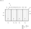
- FIG. 1 is a perspective view illustrating a battery module according to a first embodiment of the present disclosure
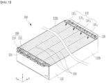
- FIG. 2 is a cut-away perspective view cut along line II-II in FIG. 1
- FIG. 3 is a cross-sectional view taken along line III-III in FIG. 1 .
- the battery module 100 includes a plurality of battery cells 110 and a housing 120 that houses the plurality of battery cells 110.
- the battery cell 110 is constituted as a pouch-type secondary battery. That is, the battery cell 110 includes an electrode assembly including a positive electrode plate, a negative electrode plate and a separator, and a rectangular cell case that houses the electrode assembly. Electrode leads electrically connected to the positive electrode plate and the negative electrode plate are protruding on the outside of the cell case.
- Such battery cells 110 are partitioned into a plurality of battery cell groups 110 1 , 110 2 , 110 3 and 110 4 , and arranged in the internal space of the housing 120.
- the battery cells 110 are comprised of four battery cell groups 110 1 , 110 2 , 110 3 and 110 4 , and one battery cell group is comprised of four battery cells, but the present disclosure is not necessarily limited thereto.
- the housing 120 which houses the plurality of battery cell groups 110 1 , 110 2 , 110 3 and 110 4 may include a module frame 122, a first end plate 124, and a second end plate 126.
- the module frame 122 may be configured as a square tubular frame consisting of a pair of first surfaces 122a and a pair of second surfaces 122b.
- the pair of first surfaces 122a consist of surfaces that are wider than the pair of second surfaces 122b
- the pair of second surfaces 122b consist of surfaces that are narrower than the pair of first surfaces 122a.
- the first pair of surfaces 122a may consist of narrow surfaces
- the pair of second surfaces 122b may consist of wide surfaces.
- the module frame 122 has a housing space in which the battery cell groups 110 1 , 110 2 , 110 3 and 110 4 can be housed, and may have a structure in which openings are arranged opposite to each other along the longitudinal direction (x).
- a module frame 122 may be formed by extrusion molding, or may be configured such that plate materials constituting the wide surface 122a and the narrow surface 122b are connected to each other by welding, screws, rivets, etc.
- the module frame 122 may be configured such that one of the pair of narrow surfaces 122b and the pair of wide surfaces 122a (the wide surface arranged at the lower part of the battery module based on the drawing) is formed as an integrated structure, and the other of the pair of wide surfaces 122a (the wide surface arranged at the upper part of the battery module based on the drawing) is coupled to the integrated structure by a cover method.
- the module frame 122 is configured as such a case.
- a first end plate (or front end plate) 124 and a second end plate (or rear end plate) 126 are fixed to both ends of the module frame 122 via welding or the like while closing the opening of the module frame 122, thereby covering both ends of the battery cell groups 110 1 , 110 2 , 110 3 and 110 4 , for example, the front and rear parts.
- the first end plate 124 and the second end plate 126 are located on the open first side (y-axis direction) and second side (-y side direction) of the module frame 122 to cover a stack of battery cell groups 110 1 , 110 2 , 110 3 and 110 4 .
- the first end plate 124 and the second end plate 126 can physically protect the stack of the battery cell groups 110 1 , 110 2 , 110 3 and 110 4 and other electrical components from external impact.
- a bus bar assembly 200 for electrically connecting the battery cells 110 to each other is arranged between the first end plate 124 and both ends of the stack of battery cell groups 110 1 , 110 2 , 110 3 and 110 4 and between the second end plate 126 and both ends of the stack of battery cell groups 110 1 , 110 2 , 110 3 and 110 4 .
- the bus bar assembly 200 includes a bus bar 210 and a bus bar frame 212.
- the bus bar 210 may be mounted on the bus bar frame 212 and electrically connected to the electrode lead of each battery cell 110.
- the bus bar frame 212 may fix the position of the bus bar 210 and physically protect the stack of battery cell groups 110 1 , 110 2 , 110 3 and 110 4 and the bus bar 210 from external impact.
- such a bus bar frame 212 is provided as one integrated structure.
- a barrier 300 is arranged between adjacent battery cell groups 110 1 , 110 2 , 110 3 and 110 4 .
- the barrier 300 prevents at least one battery cell in the battery cell groups 110 1 , 110 2 , 110 3 and 110 4 from causing thermal runaway, and high-temperature exhaust gases, exhaust byproducts (e.g., metal particles, etc.), flames, etc. discharged from the battery cell from moving to other battery cells.
- the barrier 300 is arranged between adjacent battery cell groups 110 1 , 110 2 , 110 3 and 110 4 (e.g., arranged between all four battery cell groups in this embodiment), so that it prevents the battery cells included in one battery cell group from causing thermal runway, and high-temperature exhaust gas and heat energy resulting therefrom from propagating to other battery cell groups.
- the barrier 300 constitutes compartments 310, 312, 314 and 316 for the battery cell groups 110 1 , 110 2 , 110 3 , and 110 4 together with the housing 120.
- the barrier 300 is arranged between the battery cell groups 110 1 , 110 2 , 110 3 , and 110 4 .
- the barrier 300 is supported in contact with the inner surfaces of both wide surfaces 122a of the module frame 122, as shown in FIG. 3 .
- the barrier 300 is arranged inside the module frame 122 so that its upper and lower edges about on the inner surfaces of both wide surfaces 122a of the module frame 122 based on the drawing.
- the interior of the housing 120 is provided with a plurality (four in this embodiment) of compartments 310, 312, 314 and 316 in which the barrier 300 and part of the housing 120 are connected and defined (or created).
- Corresponding battery cell groups 110 1 , 110 2 , 110 3 , and 110 4 are arranged in each of such compartments 310, 312, 314 and 316. At this time, the outermost battery cell of respective battery cell groups 110 1 , 110 2 , 110 3 and 110 4 may be in close contact with the barrier 300. Moreover, in the outermost battery cell groups 110 1 and 110 4 among the battery cell groups 110 1 , 110 2 , 110 3 and 110 4 , a pad 350 for impact absorption or the like may be arranged between the battery cell adjacent to the narrow surface 122b of the module frame 122 and the narrow surface 122b. This pad 350 may be omitted if necessary.
- the barrier 300 can maintain a fixed state by an adhesive force due to the arrangement of the battery cell groups 110 1 , 110 2 , 110 3 and 110 4 in the housing 120, and if necessary, the contact portion with the wide surface 122a can be fixed through an adhesive, welding, or the like to further strengthen the fixed state.
- the barrier 300 may be configured to include a heat-resistant material and/or a fire-resistant material.
- the barrier 300 may be configured from a glass fiber sheet, a silicon sheet, MICA, FLAME BARRIER FRB, or the like.
- the barrier 300 may be also configured from a foam pad.
- the barrier 300 may also be configured to further include a reinforcing material.
- FIG. 4 is a perspective view schematically illustrating a barrier 300 according to an embodiment of the present disclosure.
- the illustrated barrier 300 may include a reinforcing material 300a and a heat-resistant material 300b.
- the reinforcing material 300a may be, for example, a metal sheet.
- the reinforcing material 300a and the heat-resistant material 300b are provided in a rectangular shape to match the shape of the battery cell 110, and the heat-resistant material 300b is stacked on both side surfaces of the reinforcing material 300a.
- the barrier 300 of this structure is arranged between the battery cell groups 110 1 , 110 2 , 110 3 and 110 4 , it may be arranged long along the longitudinal direction (x) of the module frame 122.
- a vent part 400 is provided on at least one of the wide surfaces 122a of the module frame 122.
- the vent part 400 is for the safety of the battery cells arranged in respective compartments 310, 312, 314 and 316, and is configured to discharge not only high-temperature exhaust gases or heat discharged from the battery cell, but also flames generated by them to the outside of the housing 120.
- the vent part 400 includes through holes 400a arranged at equal intervals along the longitudinal direction (x) of the module frame 122 in the wide surface 122a of the module frame 122 (wide surface arranged at the upper part based on drawing standards).
- the through hole 400a may have an appropriate shape, and may have an appropriate size so that the module frame 122 has appropriate strength.
- vent part 400 does not overlap with the barrier 300.
- the vent part 400 is arranged in a row on the wide surface 122a of the module frame 122 corresponding to each compartment 310, 312, 314 and 316, and the barrier 300 is arranged between adjacent vent parts 400.
- the vent part 400 is in the form of a slot formed long in the longitudinal direction (x) of the module frame 122, and is provided with a through hole 400a arranged in a row at the central part of the wide surface 122a of the module frame 122 corresponding to respective compartments 310, 312, 314 and 316.
- the vent part 400 of the present disclosure is not necessarily limited thereto.
- the vent part may also be configured as a valve type.
- the battery module 100 configured in this manner is applied to devices such as electric vehicles. If a battery cell of one battery cell group 110 1 (e.g., the first battery cell group from the left side in FIG. 3 ) generates an abnormal state during operation, high-temperature gas is discharged from the battery cell, and high-temperature heat is generated within the compartment 310. This high-temperature exhaust gas and heat are cut off by the barrier 300 and do not move toward adjacent battery cell groups, for example, the compartment 312 where the second battery cell group 1102 from the left side in FIG. 3 is arranged. On the other hand, the exhaust gas and heat may rise above the housing 120 where the vent part 400 is arranged, and be discharged to the outside of the housing 120 through the through hole 400a.
- a battery cell of one battery cell group 110 1 e.g., the first battery cell group from the left side in FIG. 3
- high-temperature heat is generated within the compartment 310.
- This high-temperature exhaust gas and heat are cut off by the barrier 300 and do not move toward adjacent battery cell
- the battery module 100 can prevent or delay heat propagation from a battery cell in which thermal runaway has occurred to an adjacent battery cell by the compartment and the vent part created by the barrier 300 and the housing 120.
- FIG. 5 is a diagram illustrating a battery module 500 according to a second embodiment of the present disclosure, and is a cut-way perspective view cut along line II-II of FIG. 1 . Since the battery module 500 of the second embodiment is formed substantially in the same shape as the battery module 100 of the first embodiment, only the different configurations will be described below.
- both ends are supported in contact with the busbar frame 212 of the busbar assembly 200. That is, the upper and lower edges of the barrier 330 are in contact with the inner surface of the wide surface 122a of the module frame 122, and both end edges are in contact with the inner surface of the bus bar frame 212, based on the drawing.
- Such a barrier 330 may also allow respective battery cell groups 110 1 , 110 2 , 110 3 and 110 4 to be completely isolated into the corresponding compartments 310, 312, 314 and 316 on the bus bar assembly 200 side when the compartments 310, 312, 314 and 316 are formed within the housing 120.
- the battery module 500 of the present embodiment can reduce the occurrence of sparks by discharging exhaust gas, and the like to the outside of the housing 120 through the vent part 400 in advance. Even if a spark occurs, since the barrier 330 is arranged around the bus bar assembly 200, the generated spark can be cut off by the barrier 330, and prevented from propagating throughout the battery module 500.
- FIG. 6 is a perspective view illustrating a battery module according to a third embodiment of the present disclosure
- FIG. 7 is a cut-way perspective view taken along line VII-VII of FIG. 6 .
- the battery module 600 according to the third embodiment is formed substantially in the same shape as the battery module 100 according to the first embodiment, only the different configurations will be described below.
- the barrier 370 when the barrier 370 is arranged between the battery cell groups 110 1 , 110 2 , 110 3 , and 110 4 , at least one end edge of both ends is supported in contact with the inner surface of the end plate. Moreover, at least one of the two end plates is provided with an additional vent part.
- FIG. 6 illustrates that the right end edge of the barrier 370 is supported in contact with the inner surface of the second end plate 126.
- the bus bar frame 212 of the bus bar assembly 200 is not formed as an integral type, but is formed as a separate individual type corresponding to the battery cell groups 110 1 , 110 2 , 110 3 and 110 4 .
- the busbar frame 212 is formed with a slit (SL) into which the barrier 370 can be inserted.
- the barrier 370 may pass through the slit SL formed in the bus bar frame 212 and be in close contact with the inner surface of the second end plate 126.
- the additional vent part 450 may include additional through holes 450a, 450b, 450c and 450d formed through the front surface of the second end plate 126.
- the additional through holes 450a, 450b, 450c and 450d have an arbitrary pattern corresponding to each of the battery cell groups 110 1 , 110 2 , 110 3 and 110 4 or each of the compartments 310, 312, 314 and 316, and can be provided on the front surface of second end plate 126.
- each of the battery cell groups 110 1 , 110 2 , 110 3 and 110 4 is completely inserted into the corresponding compartments 310, 312, 314 and 316 up to the second end plate 126 side, when the compartments 310, 312, 314 and 316 are formed within the housing,
- the high-temperature exhaust gas or heat generated due to thermal runaway of the battery cells in any of the compartments 310, 312, 314 and 316 may be preferentially discharged to the outside of the housing 120 through the through holes 400a, 400b, 400c and 400d of the vent part 400. Additionally (or auxiliarily), at each side of the end plate, exhaust gas or heat can be quickly discharged to the outside of the housing 120 through the additional through holes 450a, 450b, 450c and 450d of the additional vent part 450.
- the battery module according to embodiments of the present disclosure can prevent or delay heat propagation from the battery cell in question to an adjacent cell depending on the compartment structure provided inside the housing.
- Such battery modules may be provided in plural numbers and configured as a battery pack, and the battery pack can improve the degree of freedom in a pack design by strengthening the heat propagation prevention structure due to thermal runaway provided in the battery module itself.
- the above-mentioned battery module and battery pack including the same can be applied to various devices.
- Such devices can be applied to vehicle means such as an electric bike, an electric vehicle, and a hybrid electric vehicle or ESS(Energy Storage System), but the present disclosure is not limited thereto, and also can be applied to various devices capable of using the battery module and the battery pack including the same, which falls within the scope of the present disclosure.
Landscapes
- Chemical & Material Sciences (AREA)
- Chemical Kinetics & Catalysis (AREA)
- Electrochemistry (AREA)
- General Chemical & Material Sciences (AREA)
- Engineering & Computer Science (AREA)
- Manufacturing & Machinery (AREA)
- Battery Mounting, Suspending (AREA)
- Connection Of Batteries Or Terminals (AREA)
- Gas Exhaust Devices For Batteries (AREA)
Applications Claiming Priority (3)
| Application Number | Priority Date | Filing Date | Title |
|---|---|---|---|
| KR20220169450 | 2022-12-07 | ||
| KR1020230168582A KR102945061B1 (ko) | 2022-12-07 | 2023-11-28 | 전지 모듈 및 이를 포함하는 전지 팩 |
| PCT/KR2023/020060 WO2024123097A1 (ko) | 2022-12-07 | 2023-12-07 | 전지 모듈 및 이를 포함하는 전지 팩 |
Publications (2)
| Publication Number | Publication Date |
|---|---|
| EP4481925A1 true EP4481925A1 (de) | 2024-12-25 |
| EP4481925A4 EP4481925A4 (de) | 2025-11-26 |
Family
ID=91379798
Family Applications (1)
| Application Number | Title | Priority Date | Filing Date |
|---|---|---|---|
| EP23901115.8A Pending EP4481925A4 (de) | 2022-12-07 | 2023-12-07 | Batteriemodul und batteriepack damit |
Country Status (4)
| Country | Link |
|---|---|
| US (1) | US20250210804A1 (de) |
| EP (1) | EP4481925A4 (de) |
| JP (1) | JP7823988B2 (de) |
| WO (1) | WO2024123097A1 (de) |
Family Cites Families (8)
| Publication number | Priority date | Publication date | Assignee | Title |
|---|---|---|---|---|
| KR102480098B1 (ko) * | 2016-12-23 | 2022-12-21 | 에스케이온 주식회사 | 이차 전지 모듈 |
| KR102065100B1 (ko) * | 2017-02-24 | 2020-01-10 | 주식회사 엘지화학 | 배터리 모듈 |
| US11581618B2 (en) | 2020-11-18 | 2023-02-14 | GM Global Technology Operations LLC | Thermomechanical fuses for heat propagation mitigation of electrochemical devices |
| KR102842439B1 (ko) * | 2021-01-15 | 2025-08-05 | 주식회사 엘지에너지솔루션 | 전지 모듈 및 이를 포함하는 전지팩 |
| KR102267846B1 (ko) * | 2021-04-29 | 2021-06-23 | 덕양산업 주식회사 | 분리형 배터리 모듈용 하우징 |
| KR102713991B1 (ko) * | 2021-05-20 | 2024-10-07 | 주식회사 엘지에너지솔루션 | 안전성이 향상된 배터리 모듈 |
| KR102529740B1 (ko) | 2021-06-18 | 2023-05-08 | 주식회사 포스코 | 내식성 및 표면 품질이 우수한 고내식 도금 강판 및 이의 제조방법 |
| KR102888276B1 (ko) | 2022-06-07 | 2025-11-19 | 니혼 고꾸 덴시 고교 가부시끼가이샤 | 차동 전송용 기판 세트 및 어셈블리 |
-
2023
- 2023-12-07 WO PCT/KR2023/020060 patent/WO2024123097A1/ko not_active Ceased
- 2023-12-07 US US18/850,906 patent/US20250210804A1/en active Pending
- 2023-12-07 JP JP2024552753A patent/JP7823988B2/ja active Active
- 2023-12-07 EP EP23901115.8A patent/EP4481925A4/de active Pending
Also Published As
| Publication number | Publication date |
|---|---|
| US20250210804A1 (en) | 2025-06-26 |
| JP7823988B2 (ja) | 2026-03-04 |
| JP2025508545A (ja) | 2025-03-26 |
| WO2024123097A1 (ko) | 2024-06-13 |
| EP4481925A4 (de) | 2025-11-26 |
Similar Documents
| Publication | Publication Date | Title |
|---|---|---|
| EP4435954A1 (de) | Batteriepack und vorrichtung damit | |
| EP4478513A1 (de) | Batteriemodul und batteriepack damit | |
| EP4404361A1 (de) | Batteriepack und vorrichtung damit | |
| WO2021210806A1 (ko) | 전지 팩 및 이를 포함하는 디바이스 | |
| KR20210127316A (ko) | 전지 모듈 및 이를 포함하는 전지팩 | |
| KR20230030413A (ko) | 전지 모듈 및 이를 포함하는 전지 팩 | |
| CN222029271U (zh) | 电池模块和包括该电池模块的电池组 | |
| KR102945061B1 (ko) | 전지 모듈 및 이를 포함하는 전지 팩 | |
| US20250096407A1 (en) | Battery Pack And Vehicle Including Same | |
| EP4481925A1 (de) | Batteriemodul und batteriepack damit | |
| EP4366063A1 (de) | Batteriepack und vorrichtung damit | |
| JP7843936B2 (ja) | バッテリーパック及び該バッテリーパックを含む自動車 | |
| KR102911657B1 (ko) | 배터리 팩 및 이를 포함하는 자동차 | |
| CN118975032A (zh) | 电池模块和含该电池模块的电池组 | |
| EP4475308A1 (de) | Batteriepack und fahrzeug damit | |
| US20260066440A1 (en) | Battery pack and vehicle including the same | |
| EP4645562A1 (de) | Batteriemodul, batteriepack und fahrzeug damit | |
| CN118355555A (zh) | 电池组和包括该电池组的装置 | |
| KR20250054581A (ko) | 배터리 팩 | |
| KR20260022809A (ko) | 배터리 팩, 및 이를 포함하는 자동차 | |
| KR20240012309A (ko) | 전지팩 및 이를 포함하는 디바이스 | |
| KR20260018637A (ko) | 배터리 팩 및 이를 포함하는 자동차 | |
| KR20250161241A (ko) | 배터리 모듈, 이를 포함하는 배터리 팩 및 자동차 | |
| KR20260016185A (ko) | 배터리 팩 및 이를 포함하는 자동차 | |
| CN118120102A (zh) | 电池组和包括该电池组的装置 |
Legal Events
| Date | Code | Title | Description |
|---|---|---|---|
| STAA | Information on the status of an ep patent application or granted ep patent |
Free format text: STATUS: THE INTERNATIONAL PUBLICATION HAS BEEN MADE |
|
| PUAI | Public reference made under article 153(3) epc to a published international application that has entered the european phase |
Free format text: ORIGINAL CODE: 0009012 |
|
| STAA | Information on the status of an ep patent application or granted ep patent |
Free format text: STATUS: REQUEST FOR EXAMINATION WAS MADE |
|
| 17P | Request for examination filed |
Effective date: 20240918 |
|
| AK | Designated contracting states |
Kind code of ref document: A1 Designated state(s): AL AT BE BG CH CY CZ DE DK EE ES FI FR GB GR HR HU IE IS IT LI LT LU LV MC ME MK MT NL NO PL PT RO RS SE SI SK SM TR |
|
| A4 | Supplementary search report drawn up and despatched |
Effective date: 20251028 |
|
| RIC1 | Information provided on ipc code assigned before grant |
Ipc: H01M 50/383 20210101AFI20251022BHEP Ipc: H01M 50/358 20210101ALI20251022BHEP Ipc: H01M 10/658 20140101ALI20251022BHEP Ipc: H01M 50/211 20210101ALI20251022BHEP Ipc: H01M 50/507 20210101ALI20251022BHEP Ipc: H01M 50/271 20210101ALI20251022BHEP |
|
| DAV | Request for validation of the european patent (deleted) | ||
| DAX | Request for extension of the european patent (deleted) |