EP4481869A1 - Unit cell inspection device - Google Patents
Unit cell inspection device Download PDFInfo
- Publication number
- EP4481869A1 EP4481869A1 EP23756630.2A EP23756630A EP4481869A1 EP 4481869 A1 EP4481869 A1 EP 4481869A1 EP 23756630 A EP23756630 A EP 23756630A EP 4481869 A1 EP4481869 A1 EP 4481869A1
- Authority
- EP
- European Patent Office
- Prior art keywords
- region
- electrode tab
- unit cell
- transfer
- disposed
- Prior art date
- Legal status (The legal status is an assumption and is not a legal conclusion. Google has not performed a legal analysis and makes no representation as to the accuracy of the status listed.)
- Pending
Links
Images




Classifications
-
- G—PHYSICS
- G01—MEASURING; TESTING
- G01N—INVESTIGATING OR ANALYSING MATERIALS BY DETERMINING THEIR CHEMICAL OR PHYSICAL PROPERTIES
- G01N21/00—Investigating or analysing materials by the use of optical means, i.e. using sub-millimetre waves, infrared, visible or ultraviolet light
- G01N21/84—Systems specially adapted for particular applications
- G01N21/88—Investigating the presence of flaws or contamination
- G01N21/95—Investigating the presence of flaws or contamination characterised by the material or shape of the object to be examined
-
- G—PHYSICS
- G01—MEASURING; TESTING
- G01N—INVESTIGATING OR ANALYSING MATERIALS BY DETERMINING THEIR CHEMICAL OR PHYSICAL PROPERTIES
- G01N21/00—Investigating or analysing materials by the use of optical means, i.e. using sub-millimetre waves, infrared, visible or ultraviolet light
- G01N21/84—Systems specially adapted for particular applications
- G01N21/88—Investigating the presence of flaws or contamination
- G01N21/8806—Specially adapted optical and illumination features
-
- G—PHYSICS
- G01—MEASURING; TESTING
- G01N—INVESTIGATING OR ANALYSING MATERIALS BY DETERMINING THEIR CHEMICAL OR PHYSICAL PROPERTIES
- G01N21/00—Investigating or analysing materials by the use of optical means, i.e. using sub-millimetre waves, infrared, visible or ultraviolet light
- G01N21/84—Systems specially adapted for particular applications
- G01N21/88—Investigating the presence of flaws or contamination
- G01N21/8851—Scan or image signal processing specially adapted therefor, e.g. for scan signal adjustment, for detecting different kinds of defects, for compensating for structures, markings, edges
-
- H—ELECTRICITY
- H01—ELECTRIC ELEMENTS
- H01M—PROCESSES OR MEANS, e.g. BATTERIES, FOR THE DIRECT CONVERSION OF CHEMICAL ENERGY INTO ELECTRICAL ENERGY
- H01M10/00—Secondary cells; Manufacture thereof
- H01M10/42—Methods or arrangements for servicing or maintenance of secondary cells or secondary half-cells
- H01M10/4285—Testing apparatus
-
- G—PHYSICS
- G01—MEASURING; TESTING
- G01N—INVESTIGATING OR ANALYSING MATERIALS BY DETERMINING THEIR CHEMICAL OR PHYSICAL PROPERTIES
- G01N21/00—Investigating or analysing materials by the use of optical means, i.e. using sub-millimetre waves, infrared, visible or ultraviolet light
- G01N21/84—Systems specially adapted for particular applications
- G01N2021/845—Objects on a conveyor
-
- G—PHYSICS
- G01—MEASURING; TESTING
- G01N—INVESTIGATING OR ANALYSING MATERIALS BY DETERMINING THEIR CHEMICAL OR PHYSICAL PROPERTIES
- G01N21/00—Investigating or analysing materials by the use of optical means, i.e. using sub-millimetre waves, infrared, visible or ultraviolet light
- G01N21/84—Systems specially adapted for particular applications
- G01N21/88—Investigating the presence of flaws or contamination
- G01N21/8806—Specially adapted optical and illumination features
- G01N2021/8809—Adjustment for highlighting flaws
-
- H—ELECTRICITY
- H01—ELECTRIC ELEMENTS
- H01M—PROCESSES OR MEANS, e.g. BATTERIES, FOR THE DIRECT CONVERSION OF CHEMICAL ENERGY INTO ELECTRICAL ENERGY
- H01M50/00—Constructional details or processes of manufacture of the non-active parts of electrochemical cells other than fuel cells, e.g. hybrid cells
- H01M50/50—Current conducting connections for cells or batteries
- H01M50/531—Electrode connections inside a battery casing
-
- Y—GENERAL TAGGING OF NEW TECHNOLOGICAL DEVELOPMENTS; GENERAL TAGGING OF CROSS-SECTIONAL TECHNOLOGIES SPANNING OVER SEVERAL SECTIONS OF THE IPC; TECHNICAL SUBJECTS COVERED BY FORMER USPC CROSS-REFERENCE ART COLLECTIONS [XRACs] AND DIGESTS
- Y02—TECHNOLOGIES OR APPLICATIONS FOR MITIGATION OR ADAPTATION AGAINST CLIMATE CHANGE
- Y02E—REDUCTION OF GREENHOUSE GAS [GHG] EMISSIONS, RELATED TO ENERGY GENERATION, TRANSMISSION OR DISTRIBUTION
- Y02E60/00—Enabling technologies; Technologies with a potential or indirect contribution to GHG emissions mitigation
- Y02E60/10—Energy storage using batteries
Definitions
- the present invention relates to an apparatus for inspecting a unit cell.
- secondary batteries refer to batteries, which are chargeable and dischargeable unlike non-rechargeable primary batteries, and are widely used in electronic devices such as mobile phones, notebook computers and camcorders, electric vehicles, or the like.
- lithium secondary batteries have a larger capacity and a higher energy density than nickel-cadmium batteries or nickel-hydrogen batteries, and thus utilization thereof is on a rapidly increasing trend.
- the secondary batteries may be classified into a cylindrical type battery and a prismatic type battery, each of which has an electrode assembly embedded in a cylindrical or prismatic metal can, a pouch type battery having an electrode assembly embedded in a pouch type case made of an aluminum laminate sheet, and so on.
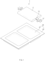
- FIG. 1 is a view illustrating an example of a pouch type secondary battery.
- a pouch type secondary battery 1 includes an electrode assembly 2, in which an electrode and a separator are provided to be alternately stacked, and a pouch 20 in which the electrode assembly 2 is accommodated.
- Each of electrode tabs 15 may be connected to the electrode of the electrode assembly 2.
- the electrode tabs 15 may be welded to each other in a predetermined area and then connected to an electrode lead 17.
- the pouch 20 includes a cup part 21 having a recessed shape for accommodating the electrode assembly 2.
- the cup part 21 of the pouch 20 may be provided in one or two.
- FIG. 1 illustrates an example of the pouch 20 including a left cup part and a right cup part.
- a circumferential part 23 (terrace) is formed around a circumference of the cup part 21 by sealing.
- an object e.g., the electrode tab of the unit cell
- An object of the present invention is to provide an apparatus for inspecting a unit cell, which is capable of preventing an object to be inspected of the unit cell from being photographed in a state of being blocked by other objects during obtaining of a photographed image of the unit cell for inspection of the unit cell, to accurately determine whether the object to be inspected is normal.
- an apparatus for inspecting a unit cell may include a transfer part, which is configured to transfer a plurality of unit cells in a predetermined transfer direction and includes a plurality of transfer rollers arranged along the transfer direction, wherein each of the plurality of unit cells comprises an electrode, and an optical inspection part which is configured to optically sense a unit cell to be inspected that is a unit cell disposed at a predetermined inspection position among the plurality of unit cells transferred by the transfer part.
- Each of the unit cells may further include an electrode tab extending from the electrode and exposed to an outside of a separator provided in each of the unit cells, the optical inspection part may be configured to set, as a region of interest (ROI), a region including a region in which at least a portion of the electrode tab is disposed at the inspection position, and an adjacent transfer roller that is a transfer roller disposed adjacent to the region of interest among the plurality of transfer rollers may be disposed so as to non-overlap the region of interest.
- ROI region of interest
- the region of interest may be set based on a region, in which the electrode tab is configured to be disposed at the inspection position during a normal transfer of the unit cell, and a region in which the electrode tab is configured to be disposed at the inspection position during a misaligned transfer of the unit cell.
- the region of interest may be set to include a region, which extends from a distal end of the separator, at which the electrode tab starts to be exposed when the electrode tab is disposed in a longitudinal direction, which is particular to the transfer direction, of the adjacent transfer roller, to the outside of the separator by a first distance in the longitudinal direction, and a region which extends from the distal end to an inside of the separator by a second distance in a direction opposite to the longitudinal direction.
- the first distance may be a length defined in the longitudinal direction and be set based on an exposure length of the electrode tab exposed from the distal end of the separator to the outside of the separator.
- the first distance may be in a range of 15 mm to 30 mm.
- the second distance may be a length defined in the longitudinal direction and be set based on an exposure length of the electrode tab exposed from the distal end of the separator to the outside of the separator, and a predetermined extra distance.
- the second distance may be in a range of 15 mm to 30 mm.
- the first distance may be less than or equal to the second distance.
- the adjacent transfer roller may be provided to have a length that does not invade the region of interest.
- the optical inspection part may include a lamp, which is configured to emit light toward the unit cell to be inspected and disposed at an upper side of the unit cell to be inspected, and a camera which is configured to photograph the unit cell to be inspected in a state in which the light is emitted by the lamp, and disposed at a lower side of the unit cell to be inspected.
- the optical inspection part may further include a reflecting plate that changes a photographing path of the camera to a direction perpendicular to the photographing path.
- the electrode tab may include a positive electrode tab and a negative electrode tab extending from a positive electrode and a negative electrode, which are one of the electrodes and the other thereof, in the longitudinal direction, which perpendicularly crosses the transfer direction, of the adjacent transfer roller and a direction opposite thereto, respectively.
- the optical inspection part may include a positive electrode tab inspection part, which optically inspects the positive electrode tab by setting, as the region of interest, a region including a region in which at least a portion of the positive electrode tab is configured to be disposed at the inspection position, and a negative electrode tab inspection part which optically inspects the negative electrode tab by setting, as the region of interest, a region including a region in which at least a portion of the negative electrode tab is configured to be disposed at the inspection position.
- the adjacent transfer roller may be disposed to at least partially overlap the unit cell to be inspected when the unit cell to be inspected is disposed at the inspection position.
- a gap between the adjacent transfer roller and another transfer roller disposed to be most adjacent to the adjacent transfer roller may be smaller than a width of the unit cell defined in the transfer direction.
- the problem may be solved in which due to the interference of the transfer roller, the optical inspection part is incapable of determining or incorrectly determines whether the electrode tab is normal, when processing the region of interest of the obtained image.
- FIG. 2 is a view illustrating an apparatus for inspecting a unit cell according to Embodiment 1 of the present invention.
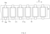
- FIG. 3 is a plan view of the inspecting apparatus in FIG. 2 when viewed from an upper side.
- the apparatus according to Embodiment 1 of the present invention is an apparatus for inspecting a unit cell 10, and, for example, may be an apparatus for inspecting electrode tabs 15a and 15b of the unit cell 10.
- the inspecting apparatus according to this embodiment may include a transfer part 110 for transferring the unit cell 10, and an optical inspection part 130 for inspecting the unit cell 10.
- the transfer part 110 may be configured to transfer the unit cells 10 in a predetermined transfer direction D1.
- the transfer part 110 may include a belt conveyor (not shown) for transferring the unit cells 10.
- the belt conveyor may include a driving roller (not shown) that supplies driving power, and an annular belt (not shown) that is circulated by the driving roller.
- the unit cells 10 may be seated on and transferred by a belt circulated by the driving roller.
- the transfer part 110 may be implemented in a manner of transferring a separating film 19.
- the electrode assembly 2 (see FIG. 1 ) constituting the battery may be configured in various types.
- the electrode assembly 2 may be configured in a stack and folding type.
- the stack and folding type electrode assembly 2 may be manufactured by using the separating film 19 to fold unit cells 10 (full-cells or bi-cells) that are provided so that electrodes 11a and 11b and a separator 13 are stacked according to a certain rule.
- the transfer part 110 may transfer the separating film 19 to transfer the unit cells 10 seated on the separating film 19 (see FIG. 3 ).
- the transfer part 110 may include the driving roller (not shown) for unwinding the separating film 19 from a roller (not shown) on which the separating film 19 is wound.
- the separating film 19 also serves as a separator, hereinafter both the separating film 19 and the separator 13 included in the unit cell 10 may be referred to as separators.
- the inspecting apparatus according to this embodiment may be disposed in front of a folding device or as a portion of the folding device.
- the transfer part 110 may include a plurality of transfer rollers 111 arranged in a transfer direction D1.
- the transfer rollers 111 may support the separating film 19 during the transfer of the separating film 19. To this end, the transfer rollers 111 may be disposed at a lower side of the separating film 19.
- the transfer rollers 111 may be idle rollers to which driving power is not supplied.
- the optical inspection part 130 may be configured to optically sense a unit cell 10' (see FIG. 2 ) to be inspected.
- the optical inspection part 130 may be configured to capture and process an image of the unit cell 10' to be inspected so as to inspect whether the unit cell 10' to be inspected is normal.
- the optical inspection part 130 may include a camera 133 (see FIG. 7 ), for example, a CCD camera, for photographing the unit cell 10' to be inspected.
- the unit cell 10' to be inspected may be a unit cell 10 that is disposed at a predetermined inspection position I (see FIG. 2 ) among the plurality of unit cells 10 transferred by the transfer part 110.
- the inspection position I may be a position at which the unit cell 10 is photographable by the camera 133 of the optical inspection part 130.
- the optical inspection part 130 may set, as a region of interest (ROI) R ( FIG. 5 ), a region including a region in which the electrode tabs 15a and 15b are disposed at the inspection position I.
- the region of interest R may be a region, which requires processing (image processing) for determining whether there is an abnormality, of the image photographed by the camera 133 of the optical inspection part 130.
- the optical inspection part 130 sets, as the region of interest R, the region including the region in which the electrode tabs 15a and 15b are disposed at the inspection position I, the electrode tabs 15a and 15b may be inspected for an abnormality.
- the region of interest R may be set to include a region in which the portion of each of the electrode tabs 15a and 15b is disposed.
- the electrode tabs 15a and 15b may extend from the electrodes 11a and 11b, respectively, and be provided in the unit cell 10 to be exposed to the outside of the separator 13 that separates the electrodes 11a and 11b from each other.
- FIG. 3 illustrates an example of the electrode tabs 15a and 15b that are exposed to the outside of the separator 13 of the unit cell 10 and also exposed to the outside of the separating film 19.
- the region of interest R is set to include a portion of one electrode tab 15a of the two electrode tabs 15a and 15b.
- a transfer roller 111' of the transfer part 110 may interfere with the photographing of the optical inspection part 130.
- the optical inspection part 130 may photograph the unit cell 10' to be inspected at a lower side of the unit cell 10' to be inspected, and, as illustrated in FIG. 4 , when the transfer roller 111' is provided to be elongated in a longitudinal direction D2 of the transfer roller 111', the transfer roller 111' may block a portion of the electrode tab 15a in a region of interest R' during the photographing of the optical inspection part 130.
- Each of the electrode tabs 15a and 15b may be folded inward to the inside of the separating film 19 for reasons such as collision with other portions during the transfer, and when the transfer roller 111' blocks the electrode tab 15a in the region of interest R', it may be difficult for the optical inspection part 130 to properly obtain the image of the electrode tab 15a folded inward to the inside of the separating film 19.
- These problems caused by blocking (or overlapping) may further occur during the meandering transfer to be described later. For example, this is because a degree to which the transfer roller blocks the region of interest may increase due to the meandering transfer compared to a case of the normal transfer.
- FIG. 4 is a view of the unit cell to be inspected disposed at the inspection position when viewed from a bottom, and is a view illustrating an example of a case in which the transfer roller blocks the electrode tab in the region of interest.
- an adjacent transfer roller 111a that is the transfer roller 111, which is disposed to be adjacent to the region of interest R among the transfer rollers 111, may be provided to non-overlap the region of interest R as illustrated in FIG. 5 .
- the adjacent transfer roller 111a may be provided to have a length that does not invade the region of interest R.
- the length of the transfer roller 111a in FIG. 5 may be less than a length of the transfer roller 111' in FIG. 4 .
- the length of the adjacent transfer roller 111a in FIG. 5 may be less than a length of the transfer roller 111' in FIG. 4 by 60 mm.
- FIG. 5 is a view of a unit cell to be inspected disposed at an inspection position when viewed from a bottom, and is a view illustrating an example of a case in which a transfer roller does not block an electrode tab in a region of interest. For reference, whether to overlap may be determined in a stacking direction of the electrode and the separator or a direction perpendicularly crossing the separating film (an upward and downward direction in FIG. 2 ).
- the apparatus for inspecting the unit cell may solve the problem that due to an interference of the transfer roller 111, the optical inspection part 130 is incapable of determining or incorrectly determines whether the electrode tabs 15a and 15b are normal, when processing the region of interest R of the obtained image.
- the adjacent transfer roller 111a may be disposed to at least partially overlap the unit cell 10' to be inspected, which is disposed at the inspection position I, in order to solve the following problems.
- FIG. 5 illustrates an example of the adjacent transfer roller 111a that partially overlaps the electrodes 11a and 11b and the separator 13 of the unit cell 10' to be inspected.
- the separating film 19 is prone to vertically sagging downward during the process.
- Pulling of the separating film may be interrupted during a folding process in the manufacturing of the stack and folding type electrode assembly (e.g., when one electrode assembly is completed and then folding of a subsequent electrode assembly is prepared). When this interruption occurs, tension applied to the separating film is decreased and thus, the separating film is prone to sagging downward.
- this sagging may further occur.
- the sagging of the separating film may further occur due to the weight of the unit cell.
- the photographed image may be distorted so that an object to be inspected is not accurately inspected.
- deformation such as wrinkles, may occur in the electrode assembly.
- the separator may appear to be a bright color, and the electrode may appear to be a dark color.
- this unit cell may be recognized as passing (or arriving) and starting the photographing (after a predetermined time) may be considered.
- a problem may occur also in this recognition to lead to a problem of a time point of starting the photographing.
- the adjacent transfer roller 111a may be provided to be disposed to at least partially overlap the unit cell 10' to be inspected to support the separating film 19 as illustrated in FIG. 5 .
- a gap between the transfer rollers 111 may be set to be small in order to support the separating film 19.
- a gap between the adjacent transfer roller 111a and another transfer roller 111 (or another adjacent transfer roller) disposed to be most adjacent to the adjacent transfer roller 111a may be smaller than a width of the unit cell defined in the transfer direction D1 (e.g., a width in a left and right direction of the electrode in FIG. 5 ).
- the adjacent transfer roller 111a may have the maximum length (see FIG. 5 ) non-overlapping the region of interest (or spaced a predetermined extra distance from the region of interest).
- the apparatus for inspecting the unit cell according to this embodiment may achieve both the prevention of the sagging of the separating film and the prevention of the interference of the adjacent transfer roller to the photographed image as described above.
- the region of interest R may be set as follows.
- the region of interest R may be set in consideration of an area A1 in which the electrode tab 15a is disposed at the inspection position I (see FIG. 2 ) during normal transfer of the unit cell 10 as illustrated in FIG. 5 .
- the normal transfer refers to a case in which the separating film 19 is transferred along a predetermined path, and may be contrasted with meandering transfer that is a case in which the separating film 19 is transferred to deviate from the predetermined path.
- the electrode tab 15a may be disposed at the area A1 of the inspection position I during the normal transfer.
- the optical inspection part 130 may determine, as an occurrence of abnormality in the electrode tab 15a, cases such as a case, in which a portion of the electrode tab 15a, which is exposed to the outside of the separating film 19, is folded to the outside of the separating film 19, or a case in which the portion of the electrode tab 15a, which is exposed to the outside of the separating film 19, is folded inward to the inside of the separating film 19.
- the region of interest R may be set to include both a region, in which the portion of the electrode tab 15a, which is exposed to the outside of the separating film 19, is disposed, and a region in which, when the portion of the electrode tab 15a, which is exposed to the outside of the separating film 19, is folded inward to the inside of the separating film 19, the portion folded inward is disposed.
- the region of interest R may be set in consideration of at least one of a first distance L1 or a second distance L2, which will be described later.
- the electrode tab 15a When the electrode tab 15a is disposed in a longitudinal direction D2 of the adjacent transfer roller 111a, which perpendicularly crosses the transfer direction D1 of the unit cell 10, the electrode tab 15a starts to be exposed from a distal end 19a of the separating film 19 in the longitudinal direction D2 to the outside of the separating film 19.
- the first distance L1 is a distance set from the distal end 19a of the separating film 19 in the longitudinal direction D2 as described above
- the second distance L2 is a distance set from the distal end 19a of the separating film 19 in a direction opposite to the longitudinal direction D2.
- the region of interest R may be set to include a region, which extends from the distal end 19a of the separating film 19 to the outside of the separating film 19 by the first distance L1, and a region which extends from the distal end 19a of the separating film 19 to the inside of the separating film 19 by the second distance L2.
- the first distance L1 may be set based on an exposure length h1 of the electrode tab 15a exposed from the distal end 19a of the separating film 19 to the outside of the separating film 19.
- the exposure length h1 of the electrode tab 15a may be a length defined in the longitudinal direction D2.
- the first distance L1 may be set to be the same as the exposure length h1 of the electrode tab 15a so that the exposed portion of the electrode tab 15a, which is disposed at the inspection position I (see FIG. 2 ), is included in the region of interest R.
- the first distance L1 may be set to be greater than the exposure length h1 as illustrated in FIG. 5 , i.e., further considering a predetermined extra distance. For example, when the exposure length h1 of the electrode tab 15a is 15 mm, the first distance L1 may be set to 15 mm to 30 mm.
- the second distance L2 may be set based on the exposure length h1 of the electrode tab 15a, which is exposed from the distal end 19a of the separating film 19 to the outside of the separating film 19, and the predetermined extra distance.
- the exposed portion of the electrode tab 15a When the exposed portion of the electrode tab 15a is entirely folded inward to the inside of the separating film 19, the exposed portion of the electrode tab 15a may be disposed inside the separating film 19 from the distal end 19a of the separating film 19 by the exposure length h1. So as for all cases including even this case to be inspected, the second distance L2 may be set in consideration of the exposure length h1 of the electrode tab 15a.
- the second distance L2 may be set in consideration of both the exposure length h1 of the electrode tab 15a and the predetermined extra distance. For example, when the exposure length h1 of the electrode tab 15a is 15 mm, the second distance L2 may be set to 15 mm to 30 mm. The second distance L2 may be greater than or equal to the first distance L1.
- the region of interest R may be set based on a region, in which the electrode tab 15a is disposed at the inspection position I during the normal transfer of the unit cell 10, and a region in which the electrode tab 15a is disposed at the inspection position I during the meandering transfer of the unit cell 10.
- the separating film 19 may be transferred in a state of being twisted for several reasons during the transfer.
- the reference symbol 19a refers to the distal end of the separating film 19 during the normal transfer
- the reference symbol 19a' refers to the distal end of the separating film 19 during the meandering transfer.
- the region of interest R may be set in consideration of both a position of the electrode tab 15a (see A1 in FIG. 5 ) during the normal transfer and a position of the electrode tab 15a (see A2 in FIG. 6 ) during the meandering transfer. Accordingly, for example, even during the meandering transfer, at least a portion of the electrode tab may be included in the region of interest, and also the transfer roller may not overlap the region of interest set as above.
- the optical inspection part 130 may be configured as follows.
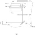
- FIG. 7 is a view specifically illustrating the optical inspection part of the inspecting apparatus in FIG. 2 .
- the optical inspection part 130 may include a lamp 131 configured to emit light toward a unit cell 10' to be inspected.
- the lamp 131 may highlight the unit cell 10' to be inspected so that the camera 133 to be described later clearly photographs the unit cell 10' to be inspected.
- the lamp 10 may be a backlight unit.
- the lamp 10 may be disposed at an upper side of the unit cell 10' to be inspected.
- the optical inspection part 130 may include a flat dome 137 to uniformly emit the light onto the unit cell 10' to be inspected at several angles.
- the optical inspection part 130 may include the camera 133 provide to photograph the unit cell 10' to be inspected in a state in which the light is emitted by the lamp 131.
- the camera 133 may be a CCD camera.
- the camera 133 may be disposed at a lower side of the unit cell 10' to be inspected as opposed to the lamp 131. Due to this arrangement, the unit cell 10' to be inspected may be disposed between the camera 133 and the lamp 131.
- the optical inspection part 130 may include a reflecting plate 135 that changes a photographing path of the camera 133 to a direction perpendicularly crossing the photographing path.
- the use of the reflecting plate 135 may increase a degree of freedom in position of the camera 133 and also reduce a size in a vertical direction of the inspecting apparatus.
- FIG. 8 is a view illustrating an apparatus for inspecting a unit cell according to Embodiment 2 of the present invention.
- the inspecting apparatus according to Embodiment 2 is provided with two inspection parts.
- the description of the inspecting apparatus according to Embodiment 2 will be focused on the difference as above.
- the same or similar matters described in Embodiment 1 may apply to Embodiment 2.
- electrode tabs 15a and 15b of a unit cell 10' to be inspected may include a positive electrode tab and a negative electrode tab extending from a positive electrode and a negative electrode, which are one of electrodes 11a and 11b and the other thereof, in the longitudinal direction D2 of an adjacent transfer roller 111a and a direction opposite thereto, respectively. That is, the positive electrode tab and the negative electrode tab may protrude in opposite directions.
- An optical inspection part 130 may include a positive electrode tab inspection part 130L for inspecting the positive electrode tab and a negative electrode tab inspection part 130R for inspecting the negative electrode tab, so as to inspect both the positive electrode tab and the negative electrode tab that protrude in the opposite directions.
- the positive electrode tab inspection part 130L may optically inspect the positive electrode tab by setting, as a region of interest R, a region including a region in which at least a portion of the positive electrode tab is disposed at inspection position I.
- the positive electrode tab inspection part 130L may include a lamp 131L, a flat dome 137L, a reflecting plate 135L, and a camera 133L, which are the same as those described in Embodiment 1.
- the negative electrode tab inspection part 130R may optically inspect the negative electrode tab by setting, as the region of interest R, a region including a region in which at least a portion of the negative electrode tab is disposed at the inspection position I.
- the negative electrode tab inspection part 130R may also include a lamp 131R, a flat dome 137R, a reflecting plate 135R, and a camera 133R, which are the same as those described in Embodiment 1.
Landscapes
- Chemical & Material Sciences (AREA)
- Immunology (AREA)
- General Health & Medical Sciences (AREA)
- Pathology (AREA)
- Engineering & Computer Science (AREA)
- General Physics & Mathematics (AREA)
- Analytical Chemistry (AREA)
- Biochemistry (AREA)
- Physics & Mathematics (AREA)
- Life Sciences & Earth Sciences (AREA)
- Health & Medical Sciences (AREA)
- Manufacturing & Machinery (AREA)
- General Chemical & Material Sciences (AREA)
- Electrochemistry (AREA)
- Chemical Kinetics & Catalysis (AREA)
- Signal Processing (AREA)
- Computer Vision & Pattern Recognition (AREA)
- Investigating Materials By The Use Of Optical Means Adapted For Particular Applications (AREA)
- Secondary Cells (AREA)
- Primary Cells (AREA)
- Connection Of Batteries Or Terminals (AREA)
Abstract
Description
- The present application claims the benefit of the priority of
Korean Patent Application Nos. 10-2022-0020455, filed on February 16, 2022 10-2023-0019638, filed on February 14, 2023 - The present invention relates to an apparatus for inspecting a unit cell.
- In general, secondary batteries refer to batteries, which are chargeable and dischargeable unlike non-rechargeable primary batteries, and are widely used in electronic devices such as mobile phones, notebook computers and camcorders, electric vehicles, or the like. In particular, lithium secondary batteries have a larger capacity and a higher energy density than nickel-cadmium batteries or nickel-hydrogen batteries, and thus utilization thereof is on a rapidly increasing trend.
- According to the shape of a battery case, the secondary batteries may be classified into a cylindrical type battery and a prismatic type battery, each of which has an electrode assembly embedded in a cylindrical or prismatic metal can, a pouch type battery having an electrode assembly embedded in a pouch type case made of an aluminum laminate sheet, and so on.
-
FIG. 1 is a view illustrating an example of a pouch type secondary battery. A pouch typesecondary battery 1 includes anelectrode assembly 2, in which an electrode and a separator are provided to be alternately stacked, and apouch 20 in which theelectrode assembly 2 is accommodated. Each ofelectrode tabs 15 may be connected to the electrode of theelectrode assembly 2. Theelectrode tabs 15 may be welded to each other in a predetermined area and then connected to anelectrode lead 17. Thepouch 20 includes acup part 21 having a recessed shape for accommodating theelectrode assembly 2. Thecup part 21 of thepouch 20 may be provided in one or two.FIG. 1 illustrates an example of thepouch 20 including a left cup part and a right cup part. A circumferential part 23 (terrace) is formed around a circumference of thecup part 21 by sealing. - It may be optically inspected during manufacturing of the
electrode assembly 2 whether a unit cell constituting theelectrode assembly 2 is normal (e.g., whether the electrode tab of the unit cell is folded). This inspection may be performed by photographing the unit cell and then analyzing a photographed image. However, when an object (e.g., the electrode tab of the unit cell) to be inspected for abnormality is blocked by other objects during obtaining of the photographed image of the unit cell, it may be difficult to analyze the obtained image to determine whether there is an abnormality. For example, when a roller disposed at a lower side of the unit cell for transfer of the unit cell blocks the electrode tab of the unit cell, it may be difficult to accurately obtain an image of the electrode tab and accordingly, it may be difficult to properly determine through the obtained image whether the electrode tab is normal. - An object of the present invention is to provide an apparatus for inspecting a unit cell, which is capable of preventing an object to be inspected of the unit cell from being photographed in a state of being blocked by other objects during obtaining of a photographed image of the unit cell for inspection of the unit cell, to accurately determine whether the object to be inspected is normal.
- In an embodiment, an apparatus for inspecting a unit cell may include a transfer part, which is configured to transfer a plurality of unit cells in a predetermined transfer direction and includes a plurality of transfer rollers arranged along the transfer direction, wherein each of the plurality of unit cells comprises an electrode, and an optical inspection part which is configured to optically sense a unit cell to be inspected that is a unit cell disposed at a predetermined inspection position among the plurality of unit cells transferred by the transfer part. Each of the unit cells may further include an electrode tab extending from the electrode and exposed to an outside of a separator provided in each of the unit cells, the optical inspection part may be configured to set, as a region of interest (ROI), a region including a region in which at least a portion of the electrode tab is disposed at the inspection position, and an adjacent transfer roller that is a transfer roller disposed adjacent to the region of interest among the plurality of transfer rollers may be disposed so as to non-overlap the region of interest.
- In another embodiment, the region of interest may be set based on a region, in which the electrode tab is configured to be disposed at the inspection position during a normal transfer of the unit cell, and a region in which the electrode tab is configured to be disposed at the inspection position during a misaligned transfer of the unit cell.
- In still another embodiment, the region of interest may be set to include a region, which extends from a distal end of the separator, at which the electrode tab starts to be exposed when the electrode tab is disposed in a longitudinal direction, which is particular to the transfer direction, of the adjacent transfer roller, to the outside of the separator by a first distance in the longitudinal direction, and a region which extends from the distal end to an inside of the separator by a second distance in a direction opposite to the longitudinal direction.
- In still another embodiment, the first distance may be a length defined in the longitudinal direction and be set based on an exposure length of the electrode tab exposed from the distal end of the separator to the outside of the separator.
- In still another embodiment, the first distance may be in a range of 15 mm to 30 mm.
- In still another embodiment, the second distance may be a length defined in the longitudinal direction and be set based on an exposure length of the electrode tab exposed from the distal end of the separator to the outside of the separator, and a predetermined extra distance.
- In still another embodiment, the second distance may be in a range of 15 mm to 30 mm.
- In still another embodiment, the first distance may be less than or equal to the second distance.
- In still another embodiment, the adjacent transfer roller may be provided to have a length that does not invade the region of interest.
- In still another embodiment, the optical inspection part may include a lamp, which is configured to emit light toward the unit cell to be inspected and disposed at an upper side of the unit cell to be inspected, and a camera which is configured to photograph the unit cell to be inspected in a state in which the light is emitted by the lamp, and disposed at a lower side of the unit cell to be inspected.
- In still another embodiment, the optical inspection part may further include a reflecting plate that changes a photographing path of the camera to a direction perpendicular to the photographing path.
- In still another embodiment, the electrode tab may include a positive electrode tab and a negative electrode tab extending from a positive electrode and a negative electrode, which are one of the electrodes and the other thereof, in the longitudinal direction, which perpendicularly crosses the transfer direction, of the adjacent transfer roller and a direction opposite thereto, respectively. The optical inspection part may include a positive electrode tab inspection part, which optically inspects the positive electrode tab by setting, as the region of interest, a region including a region in which at least a portion of the positive electrode tab is configured to be disposed at the inspection position, and a negative electrode tab inspection part which optically inspects the negative electrode tab by setting, as the region of interest, a region including a region in which at least a portion of the negative electrode tab is configured to be disposed at the inspection position.
- In still another embodiment, the adjacent transfer roller may be disposed to at least partially overlap the unit cell to be inspected when the unit cell to be inspected is disposed at the inspection position.
- In still another embodiment, a gap between the adjacent transfer roller and another transfer roller disposed to be most adjacent to the adjacent transfer roller may be smaller than a width of the unit cell defined in the transfer direction.
- According to the present invention, as the adjacent transfer roller does not invade the region of interest, the problem may be solved in which due to the interference of the transfer roller, the optical inspection part is incapable of determining or incorrectly determines whether the electrode tab is normal, when processing the region of interest of the obtained image.
-
-
FIG. 1 is a view illustrating an example of a pouch type secondary battery. -
FIG. 2 is a view illustrating an apparatus for inspecting a unit cell according toEmbodiment 1 of the present invention. -
FIG. 3 is a plan view of the inspecting apparatus inFIG. 2 when viewed from an upper side. -
FIG. 4 is a view of a unit cell to be inspected disposed at an inspection position when viewed from a bottom, and is a view illustrating an example of a case in which a transfer roller blocks an electrode tab in a region of interest. -
FIG. 5 is a view of a unit cell to be inspected disposed at an inspection position when viewed from a bottom, and is a view illustrating an example of a case in which a transfer roller does not block an electrode tab in a region of interest. -
FIG. 6 is a view of a unit cell to be inspected disposed at an inspection position when viewed from a bottom, and is a view illustrating an example of a case in which a separating film is meanderingly transferred. -
FIG. 7 is a view specifically illustrating an optical inspection part of the inspecting apparatus inFIG. 2 . -
FIG. 8 is a view illustrating an apparatus for inspecting a unit cell according toEmbodiment 2 of the present invention. - Hereinafter, preferred embodiments of the present invention will be described in detail with reference to the accompanying drawings to enable those skilled in the art to which the present invention pertains to easily carry out the present invention. The present invention may, however, be embodied in different forms and should not be construed as limited by the embodiments set forth herein.
- The parts unrelated to the description, or the detailed descriptions of related well-known art that may unnecessarily obscure subject matters of the present invention, will be ruled out in order to clearly describe the present invention. Like reference numerals refer to like elements throughout the whole specification.
- Moreover, terms or words used in this specification and claims should not be restrictively interpreted as ordinary meanings or dictionary-based meanings, but should be interpreted as meanings and concepts conforming to the scope of the present invention on the basis of the principle that an inventor can properly define the concept of a term to describe and explain his or her invention in the best ways.
-
FIG. 2 is a view illustrating an apparatus for inspecting a unit cell according toEmbodiment 1 of the present invention.FIG. 3 is a plan view of the inspecting apparatus inFIG. 2 when viewed from an upper side. The apparatus according toEmbodiment 1 of the present invention is an apparatus for inspecting aunit cell 10, and, for example, may be an apparatus for inspectingelectrode tabs unit cell 10. The inspecting apparatus according to this embodiment may include atransfer part 110 for transferring theunit cell 10, and anoptical inspection part 130 for inspecting theunit cell 10. - The
transfer part 110 may be configured to transfer theunit cells 10 in a predetermined transfer direction D1. For example, thetransfer part 110 may include a belt conveyor (not shown) for transferring theunit cells 10. The belt conveyor may include a driving roller (not shown) that supplies driving power, and an annular belt (not shown) that is circulated by the driving roller. Theunit cells 10 may be seated on and transferred by a belt circulated by the driving roller. - As illustrated in
FIG. 2 , thetransfer part 110 may be implemented in a manner of transferring a separatingfilm 19. The electrode assembly 2 (seeFIG. 1 ) constituting the battery may be configured in various types. For example, theelectrode assembly 2 may be configured in a stack and folding type. The stack and foldingtype electrode assembly 2 may be manufactured by using the separatingfilm 19 to fold unit cells 10 (full-cells or bi-cells) that are provided so thatelectrodes separator 13 are stacked according to a certain rule. Thetransfer part 110 may transfer the separatingfilm 19 to transfer theunit cells 10 seated on the separating film 19 (seeFIG. 3 ). To this end, thetransfer part 110 may include the driving roller (not shown) for unwinding the separatingfilm 19 from a roller (not shown) on which the separatingfilm 19 is wound. As the separatingfilm 19 also serves as a separator, hereinafter both the separatingfilm 19 and theseparator 13 included in theunit cell 10 may be referred to as separators. For reference, the inspecting apparatus according to this embodiment may be disposed in front of a folding device or as a portion of the folding device. - The
transfer part 110 may include a plurality oftransfer rollers 111 arranged in a transfer direction D1. Thetransfer rollers 111 may support the separatingfilm 19 during the transfer of the separatingfilm 19. To this end, thetransfer rollers 111 may be disposed at a lower side of the separatingfilm 19. Thetransfer rollers 111 may be idle rollers to which driving power is not supplied. - The
optical inspection part 130 may be configured to optically sense a unit cell 10' (seeFIG. 2 ) to be inspected. Theoptical inspection part 130 may be configured to capture and process an image of the unit cell 10' to be inspected so as to inspect whether the unit cell 10' to be inspected is normal. To this end, theoptical inspection part 130 may include a camera 133 (seeFIG. 7 ), for example, a CCD camera, for photographing the unit cell 10' to be inspected. Here, the unit cell 10' to be inspected may be aunit cell 10 that is disposed at a predetermined inspection position I (seeFIG. 2 ) among the plurality ofunit cells 10 transferred by thetransfer part 110. The inspection position I may be a position at which theunit cell 10 is photographable by thecamera 133 of theoptical inspection part 130. - The
optical inspection part 130 may set, as a region of interest (ROI) R (FIG. 5 ), a region including a region in which theelectrode tabs camera 133 of theoptical inspection part 130. As theoptical inspection part 130 sets, as the region of interest R, the region including the region in which theelectrode tabs electrode tabs electrode tabs electrode tabs electrode tabs electrodes unit cell 10 to be exposed to the outside of theseparator 13 that separates theelectrodes FIG. 3 illustrates an example of theelectrode tabs separator 13 of theunit cell 10 and also exposed to the outside of the separatingfilm 19. For reference, as an example inFIG. 5 to be described later, the region of interest R is set to include a portion of oneelectrode tab 15a of the twoelectrode tabs - When the
optical inspection part 130 photographs the unit cell 10' to be inspected, a transfer roller 111' of thetransfer part 110 may interfere with the photographing of theoptical inspection part 130. For example, theoptical inspection part 130 may photograph the unit cell 10' to be inspected at a lower side of the unit cell 10' to be inspected, and, as illustrated inFIG. 4 , when the transfer roller 111' is provided to be elongated in a longitudinal direction D2 of the transfer roller 111', the transfer roller 111' may block a portion of theelectrode tab 15a in a region of interest R' during the photographing of theoptical inspection part 130. Each of theelectrode tabs film 19 for reasons such as collision with other portions during the transfer, and when the transfer roller 111' blocks theelectrode tab 15a in the region of interest R', it may be difficult for theoptical inspection part 130 to properly obtain the image of theelectrode tab 15a folded inward to the inside of the separatingfilm 19. These problems caused by blocking (or overlapping) may further occur during the meandering transfer to be described later. For example, this is because a degree to which the transfer roller blocks the region of interest may increase due to the meandering transfer compared to a case of the normal transfer.FIG. 4 is a view of the unit cell to be inspected disposed at the inspection position when viewed from a bottom, and is a view illustrating an example of a case in which the transfer roller blocks the electrode tab in the region of interest. - In the apparatus for inspecting the unit cell according to this embodiment, in order to solve the above problems, an
adjacent transfer roller 111a that is thetransfer roller 111, which is disposed to be adjacent to the region of interest R among thetransfer rollers 111, may be provided to non-overlap the region of interest R as illustrated inFIG. 5 . For example, theadjacent transfer roller 111a may be provided to have a length that does not invade the region of interest R. The length of thetransfer roller 111a inFIG. 5 may be less than a length of the transfer roller 111' inFIG. 4 . For example, when theelectrode tabs adjacent transfer roller 111a and a direction opposite thereto, respectively (and when two regions of interest are set to correspond to the electrode tabs, respectively, as inEmbodiment 2 to be described later), the length of theadjacent transfer roller 111a inFIG. 5 may be less than a length of the transfer roller 111' inFIG. 4 by 60 mm.FIG. 5 is a view of a unit cell to be inspected disposed at an inspection position when viewed from a bottom, and is a view illustrating an example of a case in which a transfer roller does not block an electrode tab in a region of interest. For reference, whether to overlap may be determined in a stacking direction of the electrode and the separator or a direction perpendicularly crossing the separating film (an upward and downward direction inFIG. 2 ). - As the
adjacent transfer roller 111a does not invade the region of interest R, the apparatus for inspecting the unit cell according to this embodiment may solve the problem that due to an interference of thetransfer roller 111, theoptical inspection part 130 is incapable of determining or incorrectly determines whether theelectrode tabs - In this embodiment, the
adjacent transfer roller 111a may be disposed to at least partially overlap the unit cell 10' to be inspected, which is disposed at the inspection position I, in order to solve the following problems.FIG. 5 illustrates an example of theadjacent transfer roller 111a that partially overlaps theelectrodes separator 13 of the unit cell 10' to be inspected. - The separating
film 19 is prone to vertically sagging downward during the process. Pulling of the separating film may be interrupted during a folding process in the manufacturing of the stack and folding type electrode assembly (e.g., when one electrode assembly is completed and then folding of a subsequent electrode assembly is prepared). When this interruption occurs, tension applied to the separating film is decreased and thus, the separating film is prone to sagging downward. Here, when the supply of the separating film continues in the upstream of the inspecting apparatus, this sagging may further occur. In addition, when the unit cell is disposed on the separating film, the sagging of the separating film may further occur due to the weight of the unit cell. - When this sagging occurs, the photographed image may be distorted so that an object to be inspected is not accurately inspected. In addition, deformation such as wrinkles, may occur in the electrode assembly. In the photographed image, the separator may appear to be a bright color, and the electrode may appear to be a dark color. Thus, when a change from the dark color to the bright color is recognized (to this end, a trigger sensor is generally used), this unit cell may be recognized as passing (or arriving) and starting the photographing (after a predetermined time) may be considered. However, when the sagging of the separating film occurs, a problem may occur also in this recognition to lead to a problem of a time point of starting the photographing.
- In order to solve these problems, i.e., in order to prevent the sagging of the separating
film 19, theadjacent transfer roller 111a according of this embodiment may be provided to be disposed to at least partially overlap the unit cell 10' to be inspected to support the separatingfilm 19 as illustrated inFIG. 5 . Alternatively, a gap between thetransfer rollers 111 may be set to be small in order to support the separatingfilm 19. For example, a gap between theadjacent transfer roller 111a and another transfer roller 111 (or another adjacent transfer roller) disposed to be most adjacent to theadjacent transfer roller 111a may be smaller than a width of the unit cell defined in the transfer direction D1 (e.g., a width in a left and right direction of the electrode inFIG. 5 ). Accordingly, an area of the separatingfilm 19, which is not supported by the transfer roller, may be minimized. Alternatively, in order to support the separatingfilm 19, theadjacent transfer roller 111a may have the maximum length (seeFIG. 5 ) non-overlapping the region of interest (or spaced a predetermined extra distance from the region of interest). - The apparatus for inspecting the unit cell according to this embodiment may achieve both the prevention of the sagging of the separating film and the prevention of the interference of the adjacent transfer roller to the photographed image as described above.
- The region of interest R may be set as follows.
- First, the region of interest R may be set in consideration of an area A1 in which the
electrode tab 15a is disposed at the inspection position I (seeFIG. 2 ) during normal transfer of theunit cell 10 as illustrated inFIG. 5 . The normal transfer refers to a case in which the separatingfilm 19 is transferred along a predetermined path, and may be contrasted with meandering transfer that is a case in which the separatingfilm 19 is transferred to deviate from the predetermined path. As illustrated inFIG. 5 , theelectrode tab 15a may be disposed at the area A1 of the inspection position I during the normal transfer. - However, the
optical inspection part 130 may determine, as an occurrence of abnormality in theelectrode tab 15a, cases such as a case, in which a portion of theelectrode tab 15a, which is exposed to the outside of the separatingfilm 19, is folded to the outside of the separatingfilm 19, or a case in which the portion of theelectrode tab 15a, which is exposed to the outside of the separatingfilm 19, is folded inward to the inside of the separatingfilm 19. For such a determination, the region of interest R may be set to include both a region, in which the portion of theelectrode tab 15a, which is exposed to the outside of the separatingfilm 19, is disposed, and a region in which, when the portion of theelectrode tab 15a, which is exposed to the outside of the separatingfilm 19, is folded inward to the inside of the separatingfilm 19, the portion folded inward is disposed. - Second, the region of interest R may be set in consideration of at least one of a first distance L1 or a second distance L2, which will be described later. When the
electrode tab 15a is disposed in a longitudinal direction D2 of theadjacent transfer roller 111a, which perpendicularly crosses the transfer direction D1 of theunit cell 10, theelectrode tab 15a starts to be exposed from adistal end 19a of the separatingfilm 19 in the longitudinal direction D2 to the outside of the separatingfilm 19. The first distance L1 is a distance set from thedistal end 19a of the separatingfilm 19 in the longitudinal direction D2 as described above, and the second distance L2 is a distance set from thedistal end 19a of the separatingfilm 19 in a direction opposite to the longitudinal direction D2. The region of interest R may be set to include a region, which extends from thedistal end 19a of the separatingfilm 19 to the outside of the separatingfilm 19 by the first distance L1, and a region which extends from thedistal end 19a of the separatingfilm 19 to the inside of the separatingfilm 19 by the second distance L2. - The first distance L1 may be set based on an exposure length h1 of the
electrode tab 15a exposed from thedistal end 19a of the separatingfilm 19 to the outside of the separatingfilm 19. The exposure length h1 of theelectrode tab 15a may be a length defined in the longitudinal direction D2. For example, the first distance L1 may be set to be the same as the exposure length h1 of theelectrode tab 15a so that the exposed portion of theelectrode tab 15a, which is disposed at the inspection position I (seeFIG. 2 ), is included in the region of interest R. Alternatively, considering that theelectrode tab 15a may be folded or disposed to be twisted during the meandering transfer or that an extra region may be necessary during the image processing, the first distance L1 may be set to be greater than the exposure length h1 as illustrated inFIG. 5 , i.e., further considering a predetermined extra distance. For example, when the exposure length h1 of theelectrode tab 15a is 15 mm, the first distance L1 may be set to 15 mm to 30 mm. - The second distance L2 may be set based on the exposure length h1 of the
electrode tab 15a, which is exposed from thedistal end 19a of the separatingfilm 19 to the outside of the separatingfilm 19, and the predetermined extra distance. When the exposed portion of theelectrode tab 15a is entirely folded inward to the inside of the separatingfilm 19, the exposed portion of theelectrode tab 15a may be disposed inside the separatingfilm 19 from thedistal end 19a of the separatingfilm 19 by the exposure length h1. So as for all cases including even this case to be inspected, the second distance L2 may be set in consideration of the exposure length h1 of theelectrode tab 15a. Considering the twisting of theelectrode tab 15a, the extra region during the image processing, or the like, the second distance L2 may be set in consideration of both the exposure length h1 of theelectrode tab 15a and the predetermined extra distance. For example, when the exposure length h1 of theelectrode tab 15a is 15 mm, the second distance L2 may be set to 15 mm to 30 mm. The second distance L2 may be greater than or equal to the first distance L1. - Third, the region of interest R may be set based on a region, in which the
electrode tab 15a is disposed at the inspection position I during the normal transfer of theunit cell 10, and a region in which theelectrode tab 15a is disposed at the inspection position I during the meandering transfer of theunit cell 10. As illustrated inFIG. 6 , the separatingfilm 19 may be transferred in a state of being twisted for several reasons during the transfer. InFIG. 6 , thereference symbol 19a refers to the distal end of the separatingfilm 19 during the normal transfer, and thereference symbol 19a' refers to the distal end of the separatingfilm 19 during the meandering transfer. In order to inspect whether theelectrode tab 15a is normal even when the position of theelectrode tab 15a is changed due to this twisting, the region of interest R may be set in consideration of both a position of theelectrode tab 15a (see A1 inFIG. 5 ) during the normal transfer and a position of theelectrode tab 15a (see A2 inFIG. 6 ) during the meandering transfer. Accordingly, for example, even during the meandering transfer, at least a portion of the electrode tab may be included in the region of interest, and also the transfer roller may not overlap the region of interest set as above. - As illustrated in
FIG. 7 , theoptical inspection part 130 may be configured as follows.FIG. 7 is a view specifically illustrating the optical inspection part of the inspecting apparatus inFIG. 2 . - The
optical inspection part 130 may include alamp 131 configured to emit light toward a unit cell 10' to be inspected. Thelamp 131 may highlight the unit cell 10' to be inspected so that thecamera 133 to be described later clearly photographs the unit cell 10' to be inspected. Thelamp 10 may be a backlight unit. Thelamp 10 may be disposed at an upper side of the unit cell 10' to be inspected. Theoptical inspection part 130 may include aflat dome 137 to uniformly emit the light onto the unit cell 10' to be inspected at several angles. - The
optical inspection part 130 may include thecamera 133 provide to photograph the unit cell 10' to be inspected in a state in which the light is emitted by thelamp 131. Thecamera 133 may be a CCD camera. Thecamera 133 may be disposed at a lower side of the unit cell 10' to be inspected as opposed to thelamp 131. Due to this arrangement, the unit cell 10' to be inspected may be disposed between thecamera 133 and thelamp 131. - The
optical inspection part 130 may include a reflectingplate 135 that changes a photographing path of thecamera 133 to a direction perpendicularly crossing the photographing path. The use of the reflectingplate 135 may increase a degree of freedom in position of thecamera 133 and also reduce a size in a vertical direction of the inspecting apparatus. -
FIG. 8 is a view illustrating an apparatus for inspecting a unit cell according toEmbodiment 2 of the present invention. There is a difference from the inspecting apparatus according toEmbodiment 1 in that the inspecting apparatus according toEmbodiment 2 is provided with two inspection parts. Hereinafter, the description of the inspecting apparatus according toEmbodiment 2 will be focused on the difference as above. For reference, the same or similar matters described inEmbodiment 1 may apply toEmbodiment 2. - In this embodiment,
electrode tabs electrodes adjacent transfer roller 111a and a direction opposite thereto, respectively. That is, the positive electrode tab and the negative electrode tab may protrude in opposite directions. - An
optical inspection part 130 according to this embodiment may include a positive electrodetab inspection part 130L for inspecting the positive electrode tab and a negative electrodetab inspection part 130R for inspecting the negative electrode tab, so as to inspect both the positive electrode tab and the negative electrode tab that protrude in the opposite directions. - The positive electrode
tab inspection part 130L may optically inspect the positive electrode tab by setting, as a region of interest R, a region including a region in which at least a portion of the positive electrode tab is disposed at inspection position I. The positive electrodetab inspection part 130L may include alamp 131L, aflat dome 137L, a reflectingplate 135L, and acamera 133L, which are the same as those described inEmbodiment 1. - The negative electrode
tab inspection part 130R may optically inspect the negative electrode tab by setting, as the region of interest R, a region including a region in which at least a portion of the negative electrode tab is disposed at the inspection position I. The negative electrodetab inspection part 130R may also include alamp 131R, aflat dome 137R, a reflectingplate 135R, and acamera 133R, which are the same as those described inEmbodiment 1. - The description of the present invention is intended to be illustrative, and various changes and modifications can be made by those of ordinary skill in the art to which the present invention pertains, without departing from the spirit and scope of the present invention as defined by the appended claims.
- Therefore, the embodiments set forth herein are to describe the technical spirit of the present invention and not to limit. The scope of the technical spirit of the present invention is not limited by the embodiments.
- Moreover, the protective scope of the present invention should be determined by reasonable interpretation of the appended claims and all technical concepts coming within the equivalency range of the present application should be interpreted to be in the scope of the right of the present application.
Claims (14)
- An apparatus for inspecting a unit cell, the apparatus comprising:a transfer part configured to transfer a plurality of unit cells in a predetermined transfer direction, wherein the transfer part comprises a plurality of transfer rollers arranged along the transfer direction, wherein each of the plurality of unit cells comprises an electrode; andan optical inspection part configured to optically sense a unit cell to be inspected that is a unit cell disposed at a predetermined inspection position among the plurality of unit cells transferred by the transfer part,wherein each of the unit cells further comprises an electrode tab extending from the electrode and exposed to an outside of a separator provided in each of the unit cells,wherein the optical inspection part is configured to set, as a region of interest (ROI), a region comprising a region in which at least a portion of the electrode tab is disposed at the inspection position, andwherein an adjacent transfer roller that is a transfer roller disposed adjacent to the region of interest among the plurality of transfer rollers is disposed so as to not overlap the region of interest.
- The apparatus of claim 1, wherein the region of interest is set based on a region, in which the electrode tab is configured to be disposed at the inspection position during a normal transfer of the unit cell, and a region in which the electrode tab is configured to be disposed at the inspection position during a meandering transfer of the unit cell.
- The apparatus of claim 1, wherein the region of interest is set to comprise a region, which extends from a distal end of the separator, at which the electrode tab starts to be exposed when the electrode tab is disposed in a longitudinal direction, which perpendicularly crosses the transfer direction, of the adjacent transfer roller, to the outside of the separator by a first distance in the longitudinal direction, and a region which extends from the distal end to an inside of the separator by a second distance in a direction opposite to the longitudinal direction.
- The apparatus of claim 3, wherein the first distance is a length defined in the longitudinal direction and is set based on an exposure length of the electrode tab exposed from the distal end of the separator to the outside of the separator.
- The apparatus of claim 3, wherein the first distance is in a range of 15 mm to 30 mm.
- The apparatus of claim 3, wherein the second distance is a length defined in the longitudinal direction and is set based on an exposure length of the electrode tab exposed from the distal end of the separator to the outside of the separator, and a predetermined extra distance.
- The apparatus of claim 3, wherein the second distance is in a range of 15 mm to 30 mm.
- The apparatus of claim 3, wherein the first distance is less than or equal to the second distance.
- The apparatus of claim 1, wherein the adjacent transfer roller is provided to have a length that does not invade the region of interest.
- The apparatus of claim 1, wherein the optical inspection part comprises:a lamp configured to emit light toward the unit cell to be inspected and disposed at an upper side of the unit cell to be inspected; anda camera configured to photograph the unit cell to be inspected in a state in which the light is emitted by the lamp, and disposed at a lower side of the unit cell to be inspected.
- The apparatus of claim 10, wherein the optical inspection part further comprises a reflecting plate configured to change a photographing path of the camera to a direction perpendicularly crossing the photographing path.
- The apparatus of claim 1, wherein the electrode tab comprises a positive electrode tab and a negative electrode tab extending from a positive electrode and a negative electrode, which are one of the electrodes and the other thereof, in a longitudinal direction, which perpendicularly crosses the transfer direction, of the adjacent transfer roller and a direction opposite thereto, respectively,
wherein the optical inspection part comprises:a positive electrode tab inspection part configured to optically inspect the positive electrode tab by setting, as the region of interest, a region comprising a region in which at least a portion of the positive electrode tab is configured to be disposed at the inspection position; anda negative electrode tab inspection part configured to optically inspect the negative electrode tab by setting, as the region of interest, a region comprising a region in which at least a portion of the negative electrode tab is configured to be disposed at the inspection position. - The apparatus of claim 1, wherein the adjacent transfer roller is disposed to at least partially overlap the unit cell to be inspected when the unit cell to be inspected is disposed at the inspection position.
- The apparatus of claim 1, wherein a gap between the adjacent transfer roller and another transfer roller disposed immediately adjacent to the adjacent transfer roller is smaller than a width of the unit cell defined in the transfer direction.
Applications Claiming Priority (3)
| Application Number | Priority Date | Filing Date | Title |
|---|---|---|---|
| KR20220020455 | 2022-02-16 | ||
| KR1020230019638A KR20230123445A (en) | 2022-02-16 | 2023-02-14 | Inspection device for unit cell |
| PCT/KR2023/002218 WO2023158218A1 (en) | 2022-02-16 | 2023-02-15 | Unit cell inspection device |
Publications (2)
| Publication Number | Publication Date |
|---|---|
| EP4481869A1 true EP4481869A1 (en) | 2024-12-25 |
| EP4481869A4 EP4481869A4 (en) | 2025-04-30 |
Family
ID=87578603
Family Applications (1)
| Application Number | Title | Priority Date | Filing Date |
|---|---|---|---|
| EP23756630.2A Pending EP4481869A4 (en) | 2022-02-16 | 2023-02-15 | UNIT CELL INSPECTION DEVICE |
Country Status (4)
| Country | Link |
|---|---|
| US (1) | US20260009735A1 (en) |
| EP (1) | EP4481869A4 (en) |
| JP (1) | JP7831742B2 (en) |
| WO (1) | WO2023158218A1 (en) |
Families Citing this family (2)
| Publication number | Priority date | Publication date | Assignee | Title |
|---|---|---|---|---|
| KR20240159324A (en) * | 2023-04-28 | 2024-11-05 | 에스케이온 주식회사 | Method and apparatus for inspecting folding part of pouch type secondary battery |
| CN117740828B (en) * | 2024-02-20 | 2024-06-25 | 宁德时代新能源科技股份有限公司 | Encapsulation detection system and encapsulation detection method for cylindrical battery cell |
Family Cites Families (15)
| Publication number | Priority date | Publication date | Assignee | Title |
|---|---|---|---|---|
| JPS61148308A (en) * | 1984-12-22 | 1986-07-07 | Mitsubishi Heavy Ind Ltd | Visual inspection of metallic surface |
| KR102133915B1 (en) * | 2016-03-29 | 2020-07-15 | 주식회사 엘지화학 | Defect detecting system and method of electrode assembly |
| KR102090292B1 (en) * | 2016-04-15 | 2020-03-17 | 주식회사 엘지화학 | Connecting system and method for connecting electrode tap of electrode assembly |
| KR102345220B1 (en) * | 2017-02-27 | 2021-12-30 | 가부시키가이샤 인비젼 에이이에스씨 재팬 | Method for manufacturing mono cells |
| KR102167118B1 (en) * | 2017-04-26 | 2020-10-16 | 주식회사 엘지화학 | Lamination device for secondary battery |
| KR102217201B1 (en) * | 2018-03-29 | 2021-02-18 | 주식회사 엘지화학 | Apparatus for inspecting alignment of electrode assembly and method of inspecting electrode assembly using the same |
| KR101981010B1 (en) * | 2018-08-01 | 2019-08-28 | 정연길 | Equipment for manufacturing secondary battery and method for manufacturing secondary battery using the same |
| CN113196537B (en) * | 2018-12-19 | 2024-03-22 | Lg电子株式会社 | Apparatus for manufacturing cell stack of secondary battery |
| KR102771679B1 (en) * | 2019-01-16 | 2025-02-25 | 주식회사 엘지에너지솔루션 | The Apparatus And The Method For Determining Defect Of Unit Cell |
| KR102286676B1 (en) * | 2019-07-16 | 2021-08-09 | 주식회사 신룡 | Vision inspection apparatus for secondary battery |
| JP7343162B2 (en) * | 2019-09-24 | 2023-09-12 | 不二精機株式会社 | packaging equipment |
| KR20220011029A (en) * | 2020-07-20 | 2022-01-27 | 주식회사 엘지에너지솔루션 | The Apparatus And The Method For Manufacturing Unit Cell |
| KR20220020455A (en) | 2020-08-11 | 2022-02-21 | 현대자동차주식회사 | Method and apparatus for controlling vehicle using tire information |
| KR102783497B1 (en) | 2021-08-02 | 2025-03-21 | 오피이엔지(주) | Imaged multi-frequency pattern generation and transmission device |
| KR102864747B1 (en) * | 2021-08-26 | 2025-09-25 | 주식회사 엘지에너지솔루션 | Inspection device for unit cell, producing facility and method of electrode assembly including the same |
-
2023
- 2023-02-15 EP EP23756630.2A patent/EP4481869A4/en active Pending
- 2023-02-15 WO PCT/KR2023/002218 patent/WO2023158218A1/en not_active Ceased
- 2023-02-15 JP JP2024547840A patent/JP7831742B2/en active Active
- 2023-02-15 US US18/838,768 patent/US20260009735A1/en active Pending
Also Published As
| Publication number | Publication date |
|---|---|
| EP4481869A4 (en) | 2025-04-30 |
| JP2025507555A (en) | 2025-03-21 |
| WO2023158218A1 (en) | 2023-08-24 |
| US20260009735A1 (en) | 2026-01-08 |
| JP7831742B2 (en) | 2026-03-17 |
Similar Documents
| Publication | Publication Date | Title |
|---|---|---|
| KR102288122B1 (en) | Method and apparatus for manufacturing of secondary battery | |
| EP4481869A1 (en) | Unit cell inspection device | |
| EP4044306B1 (en) | Method and apparatus for manufacturing electrode assembly, and method for manufacturing secondary battery including same | |
| EP3627143B1 (en) | Alignment inspection apparatus for electrode assembly and alignment inspection method for electrode assembly using the same | |
| US8397372B2 (en) | Electrode winding apparatus | |
| CN113785425B (en) | Method of manufacturing electrode assembly, electrode assembly manufactured by the method, and secondary battery | |
| US20240039031A1 (en) | Deviation detection method and deviation detection device | |
| EP4478036A1 (en) | Electrode sheet defect inspection device | |
| KR20230123445A (en) | Inspection device for unit cell | |
| CN115428227B (en) | System for detecting defects of electrode tabs and method for detecting defects of electrode tabs using the same | |
| WO2018101634A1 (en) | Secondary battery | |
| KR102936640B1 (en) | Manufacturing method and device of electrode assembly, manufacturing method of secondary battery including the same | |
| CN118696444A (en) | Equipment for checking cell batteries | |
| CN120490108A (en) | Apparatus and method for inspecting electrode assemblies | |
| EP4431920A1 (en) | Welding inspection device | |
| JP2025536036A (en) | Electrode assembly inspection device, battery cell including electrode assembly produced using the same, battery pack including the battery cell, and automobile | |
| JP7765023B2 (en) | Stack cell that allows easy confirmation of separation membrane folds, and separation membrane inspection device and inspection method | |
| US20250015335A1 (en) | Battery manufacturing apparatus including support member and battery manufacturing method | |
| CN221596516U (en) | Device for detecting flipped electrode plates | |
| US20250096299A1 (en) | Cell assembly manufacturing device and cell assembly manufacturing method | |
| EP4726867A1 (en) | Battery case and pouch-type secondary battery including the same | |
| KR20260021403A (en) | Electrode alignnment vision inspection apparatus | |
| WO2026071617A1 (en) | Secondary battery comprising cell lead having hole for gap measurement, and method for welding cell lead | |
| JP2025528272A (en) | Electrode sheet processing device equipped with multiple detection members and electrode sheet processing method using the same | |
| EP4672417A1 (en) | ELECTRODE CELL AND MANUFACTURING METHOD FOR IT |
Legal Events
| Date | Code | Title | Description |
|---|---|---|---|
| STAA | Information on the status of an ep patent application or granted ep patent |
Free format text: STATUS: THE INTERNATIONAL PUBLICATION HAS BEEN MADE |
|
| PUAI | Public reference made under article 153(3) epc to a published international application that has entered the european phase |
Free format text: ORIGINAL CODE: 0009012 |
|
| STAA | Information on the status of an ep patent application or granted ep patent |
Free format text: STATUS: REQUEST FOR EXAMINATION WAS MADE |
|
| 17P | Request for examination filed |
Effective date: 20240812 |
|
| AK | Designated contracting states |
Kind code of ref document: A1 Designated state(s): AL AT BE BG CH CY CZ DE DK EE ES FI FR GB GR HR HU IE IS IT LI LT LU LV MC ME MK MT NL NO PL PT RO RS SE SI SK SM TR |
|
| A4 | Supplementary search report drawn up and despatched |
Effective date: 20250328 |
|
| RIC1 | Information provided on ipc code assigned before grant |
Ipc: G01N 21/88 20060101ALI20250324BHEP Ipc: H01M 50/531 20210101ALI20250324BHEP Ipc: H01M 10/04 20060101AFI20250324BHEP |
|
| DAV | Request for validation of the european patent (deleted) | ||
| DAX | Request for extension of the european patent (deleted) | ||
| STAA | Information on the status of an ep patent application or granted ep patent |
Free format text: STATUS: EXAMINATION IS IN PROGRESS |
|
| 17Q | First examination report despatched |
Effective date: 20250929 |
|
| GRAP | Despatch of communication of intention to grant a patent |
Free format text: ORIGINAL CODE: EPIDOSNIGR1 |
|
| STAA | Information on the status of an ep patent application or granted ep patent |
Free format text: STATUS: GRANT OF PATENT IS INTENDED |
|
| RIC1 | Information provided on ipc code assigned before grant |
Ipc: H01M 10/04 20060101AFI20260202BHEP Ipc: G01N 21/88 20060101ALI20260202BHEP Ipc: H01M 50/531 20210101ALI20260202BHEP Ipc: H01M 10/42 20060101ALI20260202BHEP Ipc: G01N 21/95 20060101ALI20260202BHEP |
|
| INTG | Intention to grant announced |
Effective date: 20260305 |