EP4481771A2 - Revolveranordnung - Google Patents
Revolveranordnung Download PDFInfo
- Publication number
- EP4481771A2 EP4481771A2 EP24201941.2A EP24201941A EP4481771A2 EP 4481771 A2 EP4481771 A2 EP 4481771A2 EP 24201941 A EP24201941 A EP 24201941A EP 4481771 A2 EP4481771 A2 EP 4481771A2
- Authority
- EP
- European Patent Office
- Prior art keywords
- turret
- assembly
- elbow
- housing assembly
- reinforcement
- Prior art date
- Legal status (The legal status is an assumption and is not a legal conclusion. Google has not performed a legal analysis and makes no representation as to the accuracy of the status listed.)
- Pending
Links
Images








Classifications
-
- H—ELECTRICITY
- H01—ELECTRIC ELEMENTS
- H01F—MAGNETS; INDUCTANCES; TRANSFORMERS; SELECTION OF MATERIALS FOR THEIR MAGNETIC PROPERTIES
- H01F27/00—Details of transformers or inductances, in general
- H01F27/02—Casings
-
- H—ELECTRICITY
- H01—ELECTRIC ELEMENTS
- H01F—MAGNETS; INDUCTANCES; TRANSFORMERS; SELECTION OF MATERIALS FOR THEIR MAGNETIC PROPERTIES
- H01F27/00—Details of transformers or inductances, in general
- H01F27/02—Casings
- H01F27/04—Leading of conductors or axles through casings, e.g. for tap-changing arrangements
-
- H—ELECTRICITY
- H01—ELECTRIC ELEMENTS
- H01F—MAGNETS; INDUCTANCES; TRANSFORMERS; SELECTION OF MATERIALS FOR THEIR MAGNETIC PROPERTIES
- H01F27/00—Details of transformers or inductances, in general
- H01F27/06—Mounting, supporting or suspending transformers, reactors or choke coils not being of the signal type
-
- H—ELECTRICITY
- H01—ELECTRIC ELEMENTS
- H01F—MAGNETS; INDUCTANCES; TRANSFORMERS; SELECTION OF MATERIALS FOR THEIR MAGNETIC PROPERTIES
- H01F27/00—Details of transformers or inductances, in general
- H01F27/08—Cooling; Ventilating
- H01F27/10—Liquid cooling
- H01F27/12—Oil cooling
-
- H—ELECTRICITY
- H01—ELECTRIC ELEMENTS
- H01F—MAGNETS; INDUCTANCES; TRANSFORMERS; SELECTION OF MATERIALS FOR THEIR MAGNETIC PROPERTIES
- H01F27/00—Details of transformers or inductances, in general
- H01F27/28—Coils; Windings; Conductive connections
- H01F27/32—Insulating of coils, windings, or parts thereof
Definitions
- the embodiments described herein are generally directed to turret assemblies for transformers or shunt reactors.
- a high-energy arc inside a turret or chimney between a high-voltage (“HV”) lead and a housing assembly or tank of a transformer or shunt reactor creates a sudden pressure rise which could result in oil leak, toxic fire, and part projections.
- HV high-voltage
- transformer major failure between the HV lead to chimney represent about 10% of the cases and 17% of the toxic fires in a 735 kV network. This event is a threat to personal safety, creates environmental concerns, and may lead to commercial loss as well.
- One or more embodiments are disclosed for a turret assembly that contains pressure caused by a sudden pressure rise from a high-energy arc.
- a turret assembly comprises a turret configured to contain pressure and including a circumferential outer surface, an elbow portion configured to couple to a housing assembly, and a distal portion extending distally from the elbow portion; and a coupling assembly configured to further couple the turret to the housing assembly, the coupling assembly including a reinforcement support configured to substantially surround and contact the circumferential outer surface of the turret.
- the turret includes a plurality of sections and a junction where the sections come together, and the coupling assembly includes a plurality of reinforcement supports configured to substantially circumferentially surround and contact the circumferential outer surface of the turret in at least one of the elbow portion and the distal portion at locations other than the junction;
- the elbow portion includes an elbow horizontal portion, an elbow angle portion, and an elbow vertical portion, and the coupling assembly includes a plurality of reinforcement supports configured to substantially circumferentially surround and contact the circumferential outer surface of the turret in the distal portion and at least one of the elbow horizontal portion, the elbow angle portion, and the elbow vertical portion;
- the turret includes at least one shell having a thickness greater than 8 mm;
- the coupling assembly includes at least one of reinforcement support(s), plate(s), connection plate(s), flange(s), reinforcement(s), arm(s), connection part(s), bolt(s), pin(s), weld(
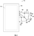
- a turret assembly 100 for a high-voltage (“HV") lead will be described.
- the turret assembly 100 is coupled to housing 110, which may be, for example, but not by way of limitation, a tank.
- housing 110 which may be, for example, but not by way of limitation, a tank.
- the turret assembly 100 of FIG. 1 and further embodiments of a turret assembly 100 shown and described with respect to FIGS. 2-16 will be described with respect to a housing assembly of a transformer 112.
- the transformer 112 is replaced with a shunt reactor; the housing assembly 110 shown and described is for a shunt reactor (not shown) instead of a transformer.
- the turret assembly 100 is configured to contain pressure caused by a sudden pressure rise from a high-energy arc, inhibiting oil leak, toxic fire, and part projections.
- the turret assembly 100 comprises a turret 180 configured to contain the above-described pressure and includes a circumferential outer surface 200.
- the turret assembly 100 further includes an elbow portion 220 having an elbow horizontal portion 222 extending laterally from the housing assembly 110, an elbow angle portion 224 extending from the elbow horizontal portion 222, and an elbow vertical portion 226 extending from the elbow angle portion 224.
- a distal portion 230 extends distally from the elbow portion 220.
- a coupling assembly 190 couples the turret assembly 100 to one or more walls 140 of the housing assembly 110.
- the coupling assembly 190 includes one or more reinforcement supports 280 configured to substantially surround and contact the circumferential outer surface 200 of the turret assembly 100 in one or more of the elbow horizontal portion 222, the elbow angle portion 224, the elbow vertical portion 226, and the distal portion 230.
- the coupling assembly 190 may include, but not by way of limitation, one or more of plates, welds, bolts, arms, and connectors, to couple the reinforcement support(s) 280 to the housing assembly 110.
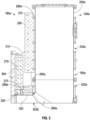
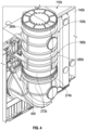
- the turret assembly 100a is coupled to transformer housing assembly 110a.
- the housing assembly 110a includes a plurality of outer walls 140a. Wall reinforcements 150 and wall reinforcement gussets 160 are included in an area 170 of the housing assembly 110a where the turret assembly 100a is coupled to one of the walls 140.
- the turret assembly 100a includes a cylindrical turret or chimney 180a and a coupling assembly 190a that couples the turret 180a to one of the walls 140a of the housing assembly 110a.
- the turret 180a is cylindrical and includes a circumferential outer surface 200a.
- the turret 180a includes an elbow portion 220a having an elbow horizontal portion 222a extending laterally from the housing assembly 110a, an elbow angle portion 224a extending from the elbow horizontal portion 222a, and an elbow vertical portion 226a extending from the elbow angle portion 224a.
- a distal portion 230a extends distally from the elbow portion 220a and includes a bushing 240.
- the turret 180 includes one or more shells 250 having a thickness greater than 8 mm, one or more flanges 260, 265 have a thickness greater than 30 mm, one or more bolts 270 have a diameter greater than m20, and the one or more bolts 270 configured for a tightening torque application greater than 300 Nm.
- the turret 180a includes a plurality of sections 272 and junction(s) 274 where the sections 272 come together.
- the coupling assembly 190a includes one or more reinforcement supports 280a that substantially circumferentially surround and contact the circumferential outer surface 200a of the turret 180a in one or more of the elbow horizontal portion 222a, the elbow angle portion 224a, the elbow vertical portion 226a, and the distal portion 230a.
- the one or more reinforcement supports 280a are preferably one or more reinforcement rings, as shown, which circumferentially surround and contact the circumferential outer surface 200a of the turret 180a around the entire circumferential surface of the cylindrical turret 180a at locations other than the junction(s) 274 in order to uniformly strengthen the turret 180a around its circumferential outer surface 200a and smoothly distribute the stress caused by a sudden pressure rise from a high-energy arc.
- One or more distal portion plates 290 are coupled to the reinforcement support(s) 280a of the distal portion 230a via a plurality of welds.
- One or more housing assembly plates 300 are coupled to the housing assembly 110a, such as via a plurality of welds and bolts 270.
- One or more connection plates 310 and a plurality of bolts 270 couple the distal portion plate 290a to the housing assembly plate 300.
- One or more elbow portion plates 320 couple the reinforcement support(s) 280a of the elbow portion 220a to the housing assembly plate(s) 300 via connection plate(s) 310, bolts 270, and welds.
- One or more elbow reinforcements 330 structurally reinforce the elbow portion 220a. Such elbow reinforcement(s) 330 may also be incorporated in the other turret assembly embodiments shown and described herein.
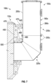
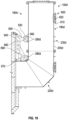
- the turret assembly 100b includes the turret 180b and a coupling assembly 190b that couples the turret 180b to one of the walls 140b of the housing assembly 110b.
- the coupling assembly 190b includes a plurality of the reinforcement supports 280b that both substantially circumferentially surround and contact the circumferential outer surface 200b of the turret 180b at locations other than the junction(s) 274b.
- Upper and central distal portion reinforcements 360, 365 are coupled to the plurality of reinforcement supports 280b of the distal portion 230b.
- Upper and central housing assembly arms 370, 375 are coupled to the housing assembly 110b.
- Upper and central turret arms 380, 385 couple the distal portion reinforcements 360, 365 to the housing assembly arms 370, 375.
- One or more bolts 270b couple the turret arms 380, 385 to the housing assembly arms 370, 375.
- One or more elbow portion reinforcements 330b are coupled to the reinforcement support(s) 280b of the elbow portion 220b.
- One or more lower housing assembly arms 390 are coupled to the housing assembly 110b.
- One or more lower turret arms 400 couple the elbow portion reinforcement(s) 330b to the lower housing assembly arm(s) 390 via bolt(s) 270b.
- One or more housing assembly plates 410 which are welded to the tank 110b, are coupled to the housing assembly 110b and the housing assembly arms 370, 375, 390.
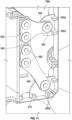
- the turret assembly 100c includes the turret 180c and a coupling assembly 190c that couples the turret 180c to one of the walls 140c of the housing assembly 110c.
- the coupling assembly 190c includes a plurality of the reinforcement supports 280c that both substantially circumferentially surround and contact the circumferential outer surface 200c of the turret 180c at locations other than the junction(s) 274c.
- One or more distal portion connectors (e.g., plates) 440 are coupled to the reinforcement supports 280c of the distal portion 230c via welds.
- One or more housing assembly connectors (e.g., plates) 450 are coupled to the housing assembly 110c via welds.
- One or more upper turret connection arms 460 couple the distal portion connector(s) 440 to the housing assembly connector(s) 450 via pins 470 and keys 480.
- One or more elbow portion connectors 490 in the elbow portion 220c are coupled to the reinforcement supports 280c of the elbow portion 220c via welds.
- One or more lower turret connection arms 490 couple the elbow portion connector(s) 500 to the housing assembly connector(s) 450 via pins 470 and keys 480.
- the turret assembly 100d includes the turret 180d and a coupling assembly 190d that couples the turret 180d to one of the walls 140d of the housing assembly 110d.
- the coupling assembly 190d includes a plurality of the reinforcement supports 280d that both substantially circumferentially surround and contact the circumferential outer surface 200d of the turret 180d at locations other than the junction(s) 274d.
- One or more distal portion plates 530 are coupled to the plurality of reinforcement supports 280d of the distal portion 230d.
- One or more housing assembly plates 540 are coupled to the housing assembly 110d.
- One or more upper connection arms 550 couple the distal portion plate(s) 530 to the housing assembly plate(s) 540 via connection pins 560.
- One or more elbow portion plates 570 are coupled to the reinforcement supports 280d of the elbow portion 220d.
- One or more lower connection arms 590 couple the elbow portion plate(s) 570 to the housing assembly plate(s) 540 via connection pins 560.
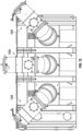
- a turret inspection cover 600 is reinforced with thicker flanges 610 of at least 20mm, and bigger bolts 620, sized at least M12. This reinforced inspection cover 600 is preferably included in all the embodiments of the turret assemblies 100, 100b, 100c, 100d, 100e, 100f shown and described herein.
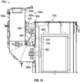
- the turret assembly 100e includes the turret 180e and a coupling assembly 190e that couples the turret 180e to one of the walls 140e of the housing assembly 110e.
- the coupling assembly 190e includes a plurality of the reinforcement supports 280e that both substantially circumferentially surround and contact the circumferential outer surface 200e of the turret 180e at locations other than the junction(s) 274e.
- One or more distal portion plates 650 are coupled to the plurality of reinforcement supports 280e of the distal portion 230e.
- One or more upper housing assembly plates 660 are coupled to the housing assembly 110e.
- One or more upper connection arms 670 couple the distal portion plate(s) 650 to the upper housing assembly plate(s) 660 via connection pins 670.
- One or more proximal plates 680 are coupled to the reinforcement supports 280e of the elbow horizontal portion 222e.
- One or more lower connection arms 690 couple the proximal plate(s) 680 to lower housing assembly plate(s) 700 via connection pins 670.
- the turret assembly 100f includes turret 180f inclined at an angle and a coupling assembly 190f that couples the inclined turret 180f to walls 140f of the housing assembly 110f.
- the coupling assembly 190f includes a plurality of the reinforcement supports 280f that both substantially circumferentially surround and contact the circumferential outer surface 200f of the inclined turret 180f at locations other than the junction(s) 274f.
- One or more distal portion plates 720 are coupled to the plurality of reinforcement supports 280f of the distal portion 230f.
- One or more upper housing assembly plates 730 are coupled to the housing assembly 110f at location(s) offset vertically relative to the elbow horizontal portion 222f of the turret 180f and the elbow portion 220f includes an elbow inclined portion 226f due to the inclined nature of the turret 180f.
- One or more upper connection arms 740 couple the distal portion plate(s) 720 to the upper housing assembly plate(s) 730 via connection pins 745.
- One or more proximal plates 750 are coupled to the reinforcement supports 280f of the elbow horizontal portion 222f.
- One or more lower connection arms 760 couple the proximal plate(s) 750 to lower housing assembly plate(s) 765 via connection pins 745.
- the turret assemblies 100, 100a, 100b, 100c, 100d, 100e, 100f are designed to resist undesirable arc energy levels that could occur on a network.
- the mechanical resistance of the turret assemblies 100, 100a, 100b, 100c, 100d, 100e, 100f is increased by the aforementioned thicker shell, thicker flanges, bigger bolts size including higher tightening torque, reinforcement support (e.g., reinforcement ring) 280, 280a, 280b, 280c, 280d, 280e, 280f to couple the turret 180, 180a, 180b, 180c, 180d, 180e, 180f to wall 140, 140a, 140b, 140c, 140d, 140e, 140f and smoothly distribute the stress, and main tank wall reinforcement(s) (e.g., wall reinforcements 150, wall reinforcement gussets 160) to attach the turret 180, 180a, 180b, 180c, 180d, 180e, 180f.
- reinforcement support e
- the load will be transferred into the housing assembly 110, 110a, 110b, 110c, 110d, 110e, 110f which may deform and absorb this energy.
- Combinations, described herein, such as “at least one of A, B, or C,” “one or more of A, B, or C,” “at least one of A, B, and C,” “one or more of A, B, and C,” and "A, B, C, or any combination thereof' include any combination of A, B, and/or C, and may include multiples of A, multiples of B, or multiples of C.
- combinations such as “at least one of A, B, or C,” “one or more of A, B, or C,” “at least one of A, B, and C,” “one or more of A, B, and C,” and "A, B, C, or any combination thereof' may be A only, B only, C only, A and B, A and C, B and C, or A and B and C, and any such combination may contain one or more members of its constituents A, B, and/or C.
- a combination of A and B may comprise one A and multiple B's, multiple A's and one B, or multiple A's and multiple B's.
- Aspect (1) pertains to a turret assembly, comprising: a turret configured to contain pressure and including a circumferential outer surface, an elbow portion configured to couple to a housing assembly, and a distal portion extending distally from the elbow portion; and a coupling assembly configured to further couple the turret to the housing assembly, the coupling assembly including a reinforcement support configured to substantially surround and contact the circumferential outer surface of the turret.
- Aspect (2) pertains to the turret assembly of Aspect (1), wherein the turret includes a plurality of sections and a junction where the sections come together, and the coupling assembly includes a plurality of reinforcement supports configured to substantially circumferentially surround and contact the circumferential outer surface of the turret in at least one of the elbow portion and the distal portion at locations other than the junction.
- Aspect (3) pertains to the turret assembly of Aspect (1), wherein the elbow portion includes an elbow horizontal portion, an elbow angle portion, and an elbow vertical portion, and the coupling assembly includes a plurality of reinforcement supports configured to substantially circumferentially surround and contact the circumferential outer surface of the turret in the distal portion and at least one of the elbow horizontal portion, the elbow angle portion, and the elbow vertical portion.
- Aspect (4) pertains to the turret assembly of any of Aspects (1) to (3), wherein the turret includes at least one shell having a thickness greater than 8 mm.
- Aspect (5) pertains to the turret assembly of any of Aspects (1) to (4), wherein the coupling assembly includes at least one of reinforcement support(s), plate(s), connection plate(s), flange(s), reinforcement(s), arm(s), connection part(s), bolt(s), pin(s), weld(s), key(s), and keyway(s).
- Aspect (6) pertains to the turret assembly of Aspect (5), wherein at least one flange has a thickness greater than 30 mm.
- Aspect (7) pertains to the turret assembly of Aspect (5), wherein at least one bolt has a diameter greater than m20.
- Aspect (8) pertains to the turret assembly of Aspect (5), wherein at least one bolt is configured for a tightening torque application greater than 300 Nm.
- Aspect (9) pertains to the turret assembly of any of Aspects (1) to (8), wherein the coupling assembly includes a plurality of reinforcement supports that both substantially circumferentially surround and contact the circumferential outer surface of the turret in the distal portion, a distal portion plate coupled to the plurality of reinforcement supports of the distal portion, a housing assembly plate configured to be coupled to the housing assembly, and a connection plate coupling the distal portion plate to the housing assembly plate.
- Aspect (10) pertains to the turret assembly of any of Aspect (9), further including an elbow portion plate coupled to the reinforcement support of the elbow portion and the housing assembly plate via the connection plate.
- Aspect (11) pertains to the turret assembly of Aspect (9) or (10), further including an elbow reinforcement configured to structurally reinforce the elbow portion.
- Aspect (12) pertains to the turret assembly of any of Aspect (1) to (8), wherein the coupling assembly includes a plurality of reinforcement supports that both substantially circumferentially surround and contact the circumferential outer surface of the turret in the distal portion, a distal portion reinforcement coupled to the plurality of reinforcement supports of the distal portion, a housing assembly arm configured to be coupled to the housing assembly, and a turret arm coupling the distal portion reinforcement to the housing assembly arm.
- Aspect (13) pertains to the turret assembly of Aspect (12), further including at least one bolt coupling the turret arm to the housing assembly arm.
- Aspect (14) pertains to the turret assembly of Aspects (12) or (13), further including an elbow portion reinforcement coupled to the reinforcement support of the elbow portion, a lower housing assembly arm configured to be coupled to the housing assembly, and a lower turret arm coupling the elbow portion reinforcement to the lower housing assembly arm.
- Aspect (15) pertains to the turret assembly of any of Aspects (12) to (14), further including a housing assembly plate configured to be coupled to the housing assembly.
- Aspect (16) pertains to the turret assembly of any of Aspects (1) to (8), wherein the coupling assembly includes a plurality of reinforcement supports that both substantially circumferentially surround and contact the circumferential outer surface of the turret in the distal portion, a distal portion connector coupled to the plurality of reinforcement supports of the distal portion, a housing assembly connector configured to be coupled to the housing assembly, and a turret arm and a plurality of connection pins coupling the distal portion connector to the housing assembly connector.
- Aspect (17) pertains to the turret assembly of Aspect (16), further including an elbow portion connector coupled to the reinforcement support of the elbow portion, a housing connector configured to be coupled to the housing assembly, and a lower turret arm and a plurality of connection pins coupling the elbow portion connector to the housing assembly connector.
- Aspect (18) pertains to the turret assembly of any of Aspects (1) to (8), wherein the coupling assembly includes a plurality of reinforcement supports that both substantially circumferentially surround and contact the circumferential outer surface of the turret in the distal portion, a distal portion plate coupled to the plurality of reinforcement supports of the distal portion, a housing assembly plate configured to be coupled to the housing assembly, and a connection arm and a plurality of connection pins coupling the distal portion plate to the housing assembly plate.
- Aspect (19) pertains to the turret assembly of Aspect (18), further including an elbow portion plate coupled to the reinforcement support of the elbow portion, and a lower connection arm and a plurality of connection pins coupling the elbow portion plate to the housing assembly plate.
- Aspect (20) pertains to the turret assembly of any of Aspects (1) to (8), wherein the elbow portion includes an elbow horizontal portion, an elbow angle portion, and an elbow inclined portion, the turret is inclined at an angle, and the coupling assembly includes a plurality of reinforcement supports that both substantially circumferentially surround and contact the circumferential outer surface of the turret in the distal portion and in at least one of the elbow horizontal portion, the elbow angle portion, and the elbow inclined portion.
- Aspect (21) pertains to the turret assembly of any of Aspects (1) to (20), further including a housing assembly configured to house an electrical component, the housing assembly comprises a tank, and the electrical component comprises at least one of a transformer and a shunt reactor housed within the tank.
- Aspect (22) pertains to the turret assembly of Aspects (1) to (21), wherein the housing assembly comprises a tank and the tank includes at least one of a tank wall reinforcements and a tank wall reinforcement gussets in an area of the tank where the turret assembly is coupled to the at least one of the plurality of outer walls.
Landscapes
- Engineering & Computer Science (AREA)
- Power Engineering (AREA)
- Housings And Mounting Of Transformers (AREA)
- Wind Motors (AREA)
- Joints Allowing Movement (AREA)
Priority Applications (1)
| Application Number | Priority Date | Filing Date | Title |
|---|---|---|---|
| EP24201941.2A EP4481771A3 (de) | 2022-02-11 | 2022-02-11 | Revolveranordnung |
Applications Claiming Priority (3)
| Application Number | Priority Date | Filing Date | Title |
|---|---|---|---|
| EP22709634.4A EP4476752B1 (de) | 2022-02-11 | 2022-02-11 | Turmaufbau |
| EP24201941.2A EP4481771A3 (de) | 2022-02-11 | 2022-02-11 | Revolveranordnung |
| PCT/EP2022/053430 WO2023151815A1 (en) | 2022-02-11 | 2022-02-11 | Turret assembly |
Related Parent Applications (2)
| Application Number | Title | Priority Date | Filing Date |
|---|---|---|---|
| EP22709634.4A Division-Into EP4476752B1 (de) | 2022-02-11 | 2022-02-11 | Turmaufbau |
| EP22709634.4A Division EP4476752B1 (de) | 2022-02-11 | 2022-02-11 | Turmaufbau |
Publications (2)
| Publication Number | Publication Date |
|---|---|
| EP4481771A2 true EP4481771A2 (de) | 2024-12-25 |
| EP4481771A3 EP4481771A3 (de) | 2025-01-15 |
Family
ID=80735946
Family Applications (3)
| Application Number | Title | Priority Date | Filing Date |
|---|---|---|---|
| EP24201941.2A Pending EP4481771A3 (de) | 2022-02-11 | 2022-02-11 | Revolveranordnung |
| EP24201944.6A Pending EP4481772A3 (de) | 2022-02-11 | 2022-02-11 | Revolveranordnung |
| EP22709634.4A Active EP4476752B1 (de) | 2022-02-11 | 2022-02-11 | Turmaufbau |
Family Applications After (2)
| Application Number | Title | Priority Date | Filing Date |
|---|---|---|---|
| EP24201944.6A Pending EP4481772A3 (de) | 2022-02-11 | 2022-02-11 | Revolveranordnung |
| EP22709634.4A Active EP4476752B1 (de) | 2022-02-11 | 2022-02-11 | Turmaufbau |
Country Status (6)
| Country | Link |
|---|---|
| US (1) | US20250157715A1 (de) |
| EP (3) | EP4481771A3 (de) |
| KR (1) | KR102725379B1 (de) |
| CN (3) | CN118919222A (de) |
| CA (1) | CA3243598A1 (de) |
| WO (1) | WO2023151815A1 (de) |
Family Cites Families (10)
| Publication number | Priority date | Publication date | Assignee | Title |
|---|---|---|---|---|
| JPS60157210A (ja) * | 1984-01-25 | 1985-08-17 | Hitachi Ltd | 油入静止誘導電器 |
| JPH0451462Y2 (de) * | 1988-04-12 | 1992-12-03 | ||
| US8319590B2 (en) * | 2011-03-21 | 2012-11-27 | Philippe Magnier Llc | Device for explosion prevention of an on load tap changer including a rupture element |
| FR2987664B1 (fr) * | 2012-03-01 | 2015-01-16 | Ecolonomie De L Ouest | Dispositif de fixation murale de mat d'eolienne |
| CN206893405U (zh) * | 2017-06-05 | 2018-01-16 | 国家电网公司 | ±1100kV特高压直流工程换流变压器套管支撑装置 |
| CN107967981A (zh) * | 2017-11-08 | 2018-04-27 | 中国南方电网有限责任公司超高压输电公司检修试验中心 | 一种提升大型变压器抗震性能的加固方法及大型变压器 |
| CN209487283U (zh) * | 2018-10-19 | 2019-10-11 | 同济大学 | 一种大型变压器升高座的支撑加固结构 |
| CN111968829B (zh) * | 2020-09-18 | 2025-08-08 | 日立能源有限公司 | 容纳部件、电气系统和操作方法 |
| CN213449739U (zh) * | 2020-09-24 | 2021-06-15 | 天津力拓得科技有限公司 | 一种塔基的稳定结构 |
| CN113898239B (zh) * | 2021-10-12 | 2023-03-14 | 上海必立结构设计事务所有限公司 | 一种简式止晃装置 |
-
2022
- 2022-02-11 CN CN202411315993.1A patent/CN118919222A/zh active Pending
- 2022-02-11 WO PCT/EP2022/053430 patent/WO2023151815A1/en not_active Ceased
- 2022-02-11 EP EP24201941.2A patent/EP4481771A3/de active Pending
- 2022-02-11 EP EP24201944.6A patent/EP4481772A3/de active Pending
- 2022-02-11 CN CN202411316254.4A patent/CN118919223A/zh active Pending
- 2022-02-11 US US18/834,927 patent/US20250157715A1/en active Pending
- 2022-02-11 CA CA3243598A patent/CA3243598A1/en active Pending
- 2022-02-11 CN CN202280091436.9A patent/CN118679535A/zh active Pending
- 2022-02-11 KR KR1020247026678A patent/KR102725379B1/ko active Active
- 2022-02-11 EP EP22709634.4A patent/EP4476752B1/de active Active
Also Published As
| Publication number | Publication date |
|---|---|
| EP4476752B1 (de) | 2025-10-01 |
| WO2023151815A1 (en) | 2023-08-17 |
| EP4481772A2 (de) | 2024-12-25 |
| KR20240128106A (ko) | 2024-08-23 |
| CN118919222A (zh) | 2024-11-08 |
| EP4481771A3 (de) | 2025-01-15 |
| CN118919223A (zh) | 2024-11-08 |
| EP4481772A3 (de) | 2025-01-15 |
| CA3243598A1 (en) | 2023-08-17 |
| US20250157715A1 (en) | 2025-05-15 |
| EP4476752A1 (de) | 2024-12-18 |
| CN118679535A (zh) | 2024-09-20 |
| KR102725379B1 (ko) | 2024-11-01 |
Similar Documents
| Publication | Publication Date | Title |
|---|---|---|
| EP4481771A2 (de) | Revolveranordnung | |
| US20160159221A1 (en) | Detachable high voltage isolation structure of large electric vehicle | |
| CN106961089A (zh) | 一种高压电缆中间接头防水防爆灭火保护壳 | |
| CN202144927U (zh) | Epr核反应堆安全壳贯穿件膨胀节 | |
| CN210510709U (zh) | 一种新型高压组合电器用金属波纹管补偿器 | |
| CN214957822U (zh) | 一种具备防爆功能的箱式变压器装置 | |
| EP4214726B1 (de) | Gehäuseteil, elektrische anlage und betriebsverfahren | |
| CN223284828U (zh) | 一种具有穿墙保护功能的换流变压器直流套管 | |
| EP0968561A1 (de) | Elektrische anschlusshülse für einen turbinengenerator | |
| CN213277684U (zh) | 容纳部件和电气系统 | |
| CN214153744U (zh) | 一种gis与变压器的连接装置 | |
| CN111968829B (zh) | 容纳部件、电气系统和操作方法 | |
| CN105304173A (zh) | 耐高温高电压高绝缘性能点火电缆 | |
| CN114121312B (zh) | 一种用于钍基熔盐实验堆的低压电气贯穿装置 | |
| CN110890674B (zh) | 电缆连接器及与其配合的连接器插座 | |
| CN217978284U (zh) | 一种具有防护功能的恒力弹簧吊架 | |
| CN217715923U (zh) | 一种烧结台车 | |
| CN101358741B (zh) | 高能防爆点火系统 | |
| CN113309786B (zh) | 一种滑动轴承及搅拌装置、混合澄清槽 | |
| CN217240168U (zh) | 一种电缆穿墙管电磁脉冲防护板安装用水冷夹套 | |
| JP2024521594A (ja) | シールドされた機器コネクタ用の着脱可能なアウタシェル、及びその分解又は組立方法 | |
| CN222939742U (zh) | 用于高压换流变压器阀侧套管的插拔式接线装置 | |
| CN114122844B (zh) | 一种适用于堆内应急供电系统的输入转接装置 | |
| CN121460355A (zh) | 一种套管防爆燃装置及变压器 | |
| CN201877272U (zh) | 一种变频谐振高压试验用漏感变压器 |
Legal Events
| Date | Code | Title | Description |
|---|---|---|---|
| PUAI | Public reference made under article 153(3) epc to a published international application that has entered the european phase |
Free format text: ORIGINAL CODE: 0009012 |
|
| STAA | Information on the status of an ep patent application or granted ep patent |
Free format text: STATUS: REQUEST FOR EXAMINATION WAS MADE |
|
| REG | Reference to a national code |
Ref country code: DE Ref legal event code: R079 Free format text: PREVIOUS MAIN CLASS: H01F0027120000 Ipc: H01F0027020000 |
|
| PUAL | Search report despatched |
Free format text: ORIGINAL CODE: 0009013 |
|
| 17P | Request for examination filed |
Effective date: 20240923 |
|
| AC | Divisional application: reference to earlier application |
Ref document number: 4476752 Country of ref document: EP Kind code of ref document: P |
|
| AK | Designated contracting states |
Kind code of ref document: A2 Designated state(s): AL AT BE BG CH CY CZ DE DK EE ES FI FR GB GR HR HU IE IS IT LI LT LU LV MC MK MT NL NO PL PT RO RS SE SI SK SM TR |
|
| AK | Designated contracting states |
Kind code of ref document: A3 Designated state(s): AL AT BE BG CH CY CZ DE DK EE ES FI FR GB GR HR HU IE IS IT LI LT LU LV MC MK MT NL NO PL PT RO RS SE SI SK SM TR |
|
| RIC1 | Information provided on ipc code assigned before grant |
Ipc: H01F 27/12 20060101ALI20241210BHEP Ipc: H01F 27/04 20060101ALI20241210BHEP Ipc: H01F 27/02 20060101AFI20241210BHEP |