EP4481765A1 - Replaceable catalyst tower - Google Patents
Replaceable catalyst tower Download PDFInfo
- Publication number
- EP4481765A1 EP4481765A1 EP23756518.9A EP23756518A EP4481765A1 EP 4481765 A1 EP4481765 A1 EP 4481765A1 EP 23756518 A EP23756518 A EP 23756518A EP 4481765 A1 EP4481765 A1 EP 4481765A1
- Authority
- EP
- European Patent Office
- Prior art keywords
- catalyst
- pull
- outer frame
- out cartridge
- packings
- Prior art date
- Legal status (The legal status is an assumption and is not a legal conclusion. Google has not performed a legal analysis and makes no representation as to the accuracy of the status listed.)
- Pending
Links
Images



Classifications
-
- G—PHYSICS
- G21—NUCLEAR PHYSICS; NUCLEAR ENGINEERING
- G21F—PROTECTION AGAINST X-RADIATION, GAMMA RADIATION, CORPUSCULAR RADIATION OR PARTICLE BOMBARDMENT; TREATING RADIOACTIVELY CONTAMINATED MATERIAL; DECONTAMINATION ARRANGEMENTS THEREFOR
- G21F9/00—Treating radioactively contaminated material; Decontamination arrangements therefor
- G21F9/04—Treating liquids
- G21F9/06—Processing
Definitions
- the present disclosure relates to a catalyst tower used in a process of removing and recovering a specific radioactive material during a radioactive waste treatment process applied in a nuclear power plant. More particularly, the present disclosure relates to a catalyst tower with a design improvement in the structure thereof.
- a catalytic exchange reaction process may be applied in order to remove a specific radioactive material (for example, tritium and so on) contained in a liquid phase by converting the specific radioactive material into a gas phase.
- a specific radioactive material for example, tritium and so on
- a catalyst tower in which a catalyst composed of platinum (Pt) and so on is applied and a packing having a structure widening an exchange reaction area is applied is used. At this time, the performance of the catalyst is reduced due to various factors such as aging or accumulation of impurities due to long-term operation, and therefore periodic or irregular replacement is required to be performed.
- the conventional catalyst tower 10 includes the outer frame 11, a support 12, the catalyst packing 13, a disperser 14, an inner frame 11b, and a collector container 19. Furthermore, the catalyst packing 13 is embedded in the inner frame 11b and is also mounted in a space between the outer frame 11 and the collector container 19. Alternatively, as described in FIG. 1(b) , all catalyst packings 13 are stacked and directly embedded inside the outer frame 11.
- mounting of the conventional catalyst tower 10 is performed such that the catalyst packings 13 are directly loaded and the internal structure is assembled at the site, and dismantling of the conventional catalyst tower 10 is performed such that the catalyst packings 13 are pulled out one by one at the site in the opposite order, so that a large space for performing the work on the site is required and a large amount of work time is required.
- an objective of the present disclosure is to provide a replaceable catalyst tower having a structure capable of remotely or quickly performing a replacement process of a catalyst packing inside the catalyst tower, thereby being capable of securing the safety of a worker and further increasing the process efficiency during a process of dismantling the catalyst tower and a process of replacing contents in the catalyst tower.
- a replaceable catalyst tower including: a outer frame formed of a rigid member, the outer frame having an open upper portion and an open lower portion; a support provided on the lower portion of the outer frame; a plurality of catalyst packings sequentially stacked on an upper portion of the support; and a disperser disposed on an upper portion or a lower portion of the catalyst packings, and a pull-out cartridge in which the plurality of catalyst packings is sequentially stacked and which has an opening that is in communication with outside, wherein the pull-out cartridge can be pulled out together with the plurality of the stacked catalyst packings for maintenance.
- the pull-out cartridge may be having an upper flange extended outward and having a predetermined area, and a bottom surface of the upper flange may be supported on an upper end of the upper portion of the outer frame, so that the pull-out cartridge capable of being conveniently pulled out.
- an upper portion of the pull-out cartridge may be open and a lower portion of the pull-out cartridge may have a window that is in communication with the outside, so that the plurality of catalyst packings stacked inside the pull-out cartridge may perform a catalytic action in a state in which the plurality of catalyst packings is stacked inside the pull-out cartridge.
- the support and the catalyst packing may be formed larger than an area of the window, so that the support and the catalyst packing may be stably stacked inside the pull-out cartridge.
- the replaceable catalyst tower may further include a sealing container having a volume capable of immediately accommodating the pull-out cartridge that is pulled out together with the catalyst packing so as to prevent radiation from leaking to a surrounding environment from the catalyst packing when the catalyst packing is pulled out from the outer frame together with the pull-out cartridge.
- the replaceable catalyst may further include a fastening member mounted such that the fastening member penetrates both the upper flange and the outer frame so that the pull-out cartridge is fixed when the pull-out cartridge is supported in the outer frame, and wherein the fastening member may be manufactured such that an upper end of the fastening member exposed to the upper portion of the outer frame is formed in a ring shape, so that fastening or dismantling of the fastening member may be conveniently performed remotely by rotating the fastening member by using a remote apparatus which has a hook shape and which passes through the ring shape.
- the catalyst tower according to the present disclosure has a structure in which the process of replacing the catalyst packing inside the catalyst tower is capable of being remotely and quickly performed, there is an effect that the safety of a worker is secured and the process efficiency is further increased during the process of dismantling the catalyst tower and the process of replacing the contents in the catalyst tower.
- a replaceable catalyst tower 100 includes an outer frame 110, a support 120, a catalyst packing 130, a disperser 140, and a pull-out cartridge 150.
- the outer frame 110 is a tower-type structure formed in a column shape that forms the external appearance of a conventional catalyst tower 10.
- the shape or the structure of the outer frame 110 is not different from an outer frame 11 that configures the conventional catalyst tower 10 illustrated in FIG. 1(a) and FIG. 1(b) , the shape or the structure of the outer frame 110 is not specifically limited.
- the support 120 is mounted on a lower portion of the catalyst packing 130 that will be described later, and serves to support the catalyst packing 130.
- the catalyst packing 130 performs an action of an exchange reaction using a catalyst so that a specific radioactive substance (for example, tritium and so on) contained in a liquid phase is capable of being moved to a gas phase.
- a specific radioactive substance for example, tritium and so on
- the disperser 140 performs an action of preventing channeling of a liquid that is coming down from an upper portion of the disperser 140 and of evenly dispersing the liquid in the catalyst packing 130.
- the pull-out cartridge 150 is a configuration introduced in the replaceable catalyst tower 100 according to the present disclosure, and is a container-type structure having a predetermined volume so that the catalyst packings 130 are capable of being sequentially stacked inside the structure.
- an opening that is in communication with connected to the outside at both upper and lower portions of the replaceable catalyst tower 100 is illustrated in FIG. 2 .
- the cartridge packing 130 may perform an original catalytic action.
- the pull-out cartridge 150 is pulled out, so that the plurality of stacked catalyst packings 130 is capable of being pulled out together with the pull-out cartridge 150 while being in a state in which the plurality of stacked catalyst packings 130 is stacked inside the pull-out cartridge 150.
- a structure allowing the pull-out cartridge 150 to be conveniently mounted in the catalyst tower 100 has a shape in which the pull-out cartridge 150 extends toward outside of the side surface of the pull-out cartridge 150, and an upper flange 151 having a predetermined area is formed on the pull-out cartridge 150, so that the pull-out cartridge 150 may be mounted such that the pull-out cartridge 150 is capable of being conveniently pulled out since the bottom surface of the upper flange 151 is supported on the upper portion of the upper end of the outer frame 110.
- a fastening member 170 mounted such that the fastening member 170 penetrates both the upper flange 151 and the outer frame 110 so that the pull-out cartridge 150 is capable of being fixed when the pull-out cartridge 150 is supported in the outer frame 110 may be further provided.
- the fastening member 170 is manufactured such that the upper end of the fastening member 170 exposed to the upper portion of the outer frame 110 is formed in a ring shape, so that fastening or dismantling of the fastening member 170 may be conveniently performed remotely by rotating the fastening member 170 by using a remote apparatus (not illustrated) which has a hook shape and which passes through the ring shape.
- an eye bolt may be representatively adopted as the fastening member 170 in which the upper end of the fastening member 170 is formed in the ring shape.
- the eye bolt when the pull-out cartridge 150 is to be pulled out from the catalyst tower 100, the eye bolt may be dismantled when a hook of an a stick-type apparatus (not illustrated) having the hook mounted on the distal end of the stick-type apparatus is caught in the eye bolt and the stick-type apparatus is rotated remotely during the process of dismantling the fastening member 170, so that an unmanned remote apparatus for disassembling may be simplified (not illustrated).
- the upper portion of the pull-out cartridge 150 is open and the lower portion of the pull-out cartridge 150 has a window in communication with the outside as illustrated in FIG. 2 and FIG. 3 , the plurality of catalyst packings 130 stacked inside the pull-out cartridge 150 may perform the catalytic action while being in a state in which the plurality of catalyst packings 130 is stacked inside the pull-out cartridge 150.
- the support 120 and the catalyst packing 130 may be stably stacked inside the pull-out cartridge and the catalyst packing 130 may smoothly perform the catalytic action without the risk of falling of the support 120 and the catalyst packing 130 through the window.
- the upper flange 151 is widely formed with the predetermined area, at least two catalyst towers 100 may be connected in series in a vertical direction as illustrated in FIG. 4 . In this situation, the catalytic effect may be further increased.
- the pull-out cartridge 150 may be conveniently mounted and also may function as a stable support for a series connection for enhancing the catalyst performance.
- a sealing container 180 having a volume capable of immediately accommodating the pull-out cartridge 150 that is pulled out together with the catalyst packing 130 so as to prevent radiation from leaking from the catalyst packing 130 while the catalyst packing 130 is pulled out from the outer frame 110 together with the pull-out cartridge 150 may be further provided.
Landscapes
- Physics & Mathematics (AREA)
- Engineering & Computer Science (AREA)
- General Engineering & Computer Science (AREA)
- High Energy & Nuclear Physics (AREA)
- Devices And Processes Conducted In The Presence Of Fluids And Solid Particles (AREA)
Abstract
Description
- The present disclosure relates to a catalyst tower used in a process of removing and recovering a specific radioactive material during a radioactive waste treatment process applied in a nuclear power plant. More particularly, the present disclosure relates to a catalyst tower with a design improvement in the structure thereof.
- In a radioactive waste treatment process of a nuclear power plant, a catalytic exchange reaction process may be applied in order to remove a specific radioactive material (for example, tritium and so on) contained in a liquid phase by converting the specific radioactive material into a gas phase. Generally, since a gas-liquid exchange reaction is not easily realized, a catalyst tower in which a catalyst composed of platinum (Pt) and so on is applied and a packing having a structure widening an exchange reaction area is applied is used. At this time, the performance of the catalyst is reduced due to various factors such as aging or accumulation of impurities due to long-term operation, and therefore periodic or irregular replacement is required to be performed.
- However, setting of a conventional catalyst tower 10 is performed such that a
catalyst packing 13 is directly loaded inside anouter frame 11 and an internal structure is assembled or dismantled at the site. - More specifically, as illustrated in
FIG. 1(a) , the conventional catalyst tower 10 includes theouter frame 11, asupport 12, thecatalyst packing 13, adisperser 14, aninner frame 11b, and acollector container 19. Furthermore, thecatalyst packing 13 is embedded in theinner frame 11b and is also mounted in a space between theouter frame 11 and thecollector container 19. Alternatively, as described inFIG. 1(b) , allcatalyst packings 13 are stacked and directly embedded inside theouter frame 11. - Therefore, conventionally, mounting of the conventional catalyst tower 10 is performed such that the
catalyst packings 13 are directly loaded and the internal structure is assembled at the site, and dismantling of the conventional catalyst tower 10 is performed such that thecatalyst packings 13 are pulled out one by one at the site in the opposite order, so that a large space for performing the work on the site is required and a large amount of work time is required. - Particularly, in a place such as nuclear facilities, when a radioactive material is handled or when a worker is exposed to the radioactive material during operating the nuclear facilities, in addition to space and time issues, there is a problem that it is difficult to prevent the worker from being exposed to radiation during replacing or dismantling of the internal structure of the catalyst tower 10.
-
Korean Patent Application Publication No. 10-2021-0154115 (published on December 20, 2021 - Accordingly, the present disclosure has been made keeping in mind the above problems occurring in the related art, and an objective of the present disclosure is to provide a replaceable catalyst tower having a structure capable of remotely or quickly performing a replacement process of a catalyst packing inside the catalyst tower, thereby being capable of securing the safety of a worker and further increasing the process efficiency during a process of dismantling the catalyst tower and a process of replacing contents in the catalyst tower.
- In order to achieve the objective of the present disclosure, there is provided a replaceable catalyst tower including: a outer frame formed of a rigid member, the outer frame having an open upper portion and an open lower portion; a support provided on the lower portion of the outer frame; a plurality of catalyst packings sequentially stacked on an upper portion of the support; and a disperser disposed on an upper portion or a lower portion of the catalyst packings, and a pull-out cartridge in which the plurality of catalyst packings is sequentially stacked and which has an opening that is in communication with outside, wherein the pull-out cartridge can be pulled out together with the plurality of the stacked catalyst packings for maintenance.
- Here, preferably, the pull-out cartridge may be having an upper flange extended outward and having a predetermined area, and a bottom surface of the upper flange may be supported on an upper end of the upper portion of the outer frame, so that the pull-out cartridge capable of being conveniently pulled out.
- At this time, preferably, an upper portion of the pull-out cartridge may be open and a lower portion of the pull-out cartridge may have a window that is in communication with the outside, so that the plurality of catalyst packings stacked inside the pull-out cartridge may perform a catalytic action in a state in which the plurality of catalyst packings is stacked inside the pull-out cartridge.
- In this situation, preferably, the support and the catalyst packing may be formed larger than an area of the window, so that the support and the catalyst packing may be stably stacked inside the pull-out cartridge.
- Particularly, preferably, the replaceable catalyst tower may further include a sealing container having a volume capable of immediately accommodating the pull-out cartridge that is pulled out together with the catalyst packing so as to prevent radiation from leaking to a surrounding environment from the catalyst packing when the catalyst packing is pulled out from the outer frame together with the pull-out cartridge.
- In addition, preferably, the replaceable catalyst may further include a fastening member mounted such that the fastening member penetrates both the upper flange and the outer frame so that the pull-out cartridge is fixed when the pull-out cartridge is supported in the outer frame, and wherein the fastening member may be manufactured such that an upper end of the fastening member exposed to the upper portion of the outer frame is formed in a ring shape, so that fastening or dismantling of the fastening member may be conveniently performed remotely by rotating the fastening member by using a remote apparatus which has a hook shape and which passes through the ring shape.
- Since the catalyst tower according to the present disclosure has a structure in which the process of replacing the catalyst packing inside the catalyst tower is capable of being remotely and quickly performed, there is an effect that the safety of a worker is secured and the process efficiency is further increased during the process of dismantling the catalyst tower and the process of replacing the contents in the catalyst tower.
-
-
FIG. 1(a) and FIG. 1(b) are conceptual views illustrating two conventional catalyst towers. -
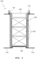
FIG. 2 is a conceptual view illustrating a catalyst tower according to the present disclosure. -
FIG. 3 is an exploded view ofFIG. 2 . -
FIG. 4 is a conceptual view illustrating an additional embodiment inFIG. 2 . -
FIG. 5 is a conceptual view sequentially illustrating a process of dismantling the catalyst tower according to the present disclosure. - Specific structures and functions stated in the following embodiments of the present disclosure are exemplified to illustrate embodiments according to the spirit of the present disclosure and the embodiments according to the spirit of the present disclosure can be achieved in various ways. Furthermore, the present disclosure should not be construed as being limited to the following embodiments and should be construed as including all changes, equivalents, and replacements included in the spirit and scope of the present disclosure.
- Hereinafter, the present disclosure will be described in detail with reference to the accompanying drawings.
- As illustrated in
FIG. 2 , areplaceable catalyst tower 100 includes anouter frame 110, asupport 120, acatalyst packing 130, adisperser 140, and a pull-out cartridge 150. - As illustrated in
FIG. 1(a) and FIG. 1(b) , theouter frame 110 is a tower-type structure formed in a column shape that forms the external appearance of a conventional catalyst tower 10. - Here, since the shape or the structure of the
outer frame 110 is not different from anouter frame 11 that configures the conventional catalyst tower 10 illustrated inFIG. 1(a) and FIG. 1(b) , the shape or the structure of theouter frame 110 is not specifically limited. - The
support 120 is mounted on a lower portion of thecatalyst packing 130 that will be described later, and serves to support thecatalyst packing 130. - The
catalyst packing 130 performs an action of an exchange reaction using a catalyst so that a specific radioactive substance (for example, tritium and so on) contained in a liquid phase is capable of being moved to a gas phase. - The
disperser 140 performs an action of preventing channeling of a liquid that is coming down from an upper portion of thedisperser 140 and of evenly dispersing the liquid in thecatalyst packing 130. - The pull-
out cartridge 150 is a configuration introduced in thereplaceable catalyst tower 100 according to the present disclosure, and is a container-type structure having a predetermined volume so that thecatalyst packings 130 are capable of being sequentially stacked inside the structure. In addition, as illustrated inFIG. 2 , an opening that is in communication with connected to the outside at both upper and lower portions of thereplaceable catalyst tower 100. - Therefore, even in a state in which the
cartridge packing 130 is mounted inside the pull-outcartridge 150, when the pull-outcartridge 150 is mounted in theouter frame 110, thecartridge packing 130 may perform an original catalytic action. - In addition, when the
catalyst packing 130 is pulled out for maintenance of thecatalyst packing 130, the pull-outcartridge 150 is pulled out, so that the plurality of stackedcatalyst packings 130 is capable of being pulled out together with the pull-outcartridge 150 while being in a state in which the plurality of stackedcatalyst packings 130 is stacked inside the pull-outcartridge 150. - Therefore, in a situation in which the
catalyst packings 130 are mounted, when the pull-outcartridge 150 in which thecartridge packings 130 are stacked is mounted, there is an effect that thecatalyst packings 130 are mounted together with the pull-outcartridge 150, and an additional dismantling process is not required when thecatalyst packings 130 are dismantled for maintenance. - Therefore, a problem of a risk of a worker being exposed to radiation from a
catalyst packing 13 during a process of dismantling the conventional catalyst tower 10 may be prevented, and a process of mounting and dismantling thecatalyst tower 100 may be performed significantly quickly and conveniently. - More specifically, as illustrated in
FIG. 2 , a structure allowing the pull-outcartridge 150 to be conveniently mounted in thecatalyst tower 100 has a shape in which the pull-outcartridge 150 extends toward outside of the side surface of the pull-outcartridge 150, and anupper flange 151 having a predetermined area is formed on the pull-outcartridge 150, so that the pull-outcartridge 150 may be mounted such that the pull-outcartridge 150 is capable of being conveniently pulled out since the bottom surface of theupper flange 151 is supported on the upper portion of the upper end of theouter frame 110. - In this situation, as illustrated in
FIG. 2 , afastening member 170 mounted such that thefastening member 170 penetrates both theupper flange 151 and theouter frame 110 so that the pull-outcartridge 150 is capable of being fixed when the pull-outcartridge 150 is supported in theouter frame 110 may be further provided. - Particularly, here, the
fastening member 170 is manufactured such that the upper end of thefastening member 170 exposed to the upper portion of theouter frame 110 is formed in a ring shape, so that fastening or dismantling of thefastening member 170 may be conveniently performed remotely by rotating thefastening member 170 by using a remote apparatus (not illustrated) which has a hook shape and which passes through the ring shape. - In this situation, an eye bolt may be representatively adopted as the fastening
member 170 in which the upper end of the fasteningmember 170 is formed in the ring shape. In a situation in which the eye bolt is adopted as the fasteningmember 170, when the pull-outcartridge 150 is to be pulled out from thecatalyst tower 100, the eye bolt may be dismantled when a hook of an a stick-type apparatus (not illustrated) having the hook mounted on the distal end of the stick-type apparatus is caught in the eye bolt and the stick-type apparatus is rotated remotely during the process of dismantling the fasteningmember 170, so that an unmanned remote apparatus for disassembling may be simplified (not illustrated). - In addition, as described above, the upper portion of the pull-out
cartridge 150 is open and the lower portion of the pull-outcartridge 150 has a window in communication with the outside as illustrated inFIG. 2 andFIG. 3 , the plurality ofcatalyst packings 130 stacked inside the pull-outcartridge 150 may perform the catalytic action while being in a state in which the plurality ofcatalyst packings 130 is stacked inside the pull-outcartridge 150. - In this situation, since the area of the bottom surface of each of the
support 120 and thecatalyst packing 130 is formed larger than the area of the window, thesupport 120 and thecatalyst packing 130 may be stably stacked inside the pull-out cartridge and thecatalyst packing 130 may smoothly perform the catalytic action without the risk of falling of thesupport 120 and the catalyst packing 130 through the window. - In addition, since the
upper flange 151 is widely formed with the predetermined area, at least twocatalyst towers 100 may be connected in series in a vertical direction as illustrated inFIG. 4 . In this situation, the catalytic effect may be further increased. - Therefore, by the
upper flange 151, the pull-outcartridge 150 may be conveniently mounted and also may function as a stable support for a series connection for enhancing the catalyst performance. - Meanwhile, as illustrated in the rightmost drawing in
FIG. 5 , asealing container 180 having a volume capable of immediately accommodating the pull-outcartridge 150 that is pulled out together with thecatalyst packing 130 so as to prevent radiation from leaking from thecatalyst packing 130 while thecatalyst packing 130 is pulled out from theouter frame 110 together with the pull-outcartridge 150 may be further provided. - In the conventional catalyst tower 10 as illustrated in
FIG. 1 , when thecatalyst packing 13 is to be stored in thesealing container 180 the same as illustrated in the rightmost drawing inFIG. 5 in order to prevent radiation exposure from thecatalyst packing 13 that has finished the catalytic action, a certain level of radiation exposure may occur during sequentially loading each catalyst packing 13 into thesealing container 180, so that the safety of the worker is a concern and a considerable amount of time of the work process may be required. - However, in the
replaceable catalyst tower 100 according to the present disclosure, when the pull-outcartridge 150 is pulled-out and then loaded into the sealingcontainer 180, allcatalyst packings 130 may be stored in the sealingcontainer 180 together with the pull-outcartridge 150. Therefore, radiation exposure during the process of moving the catalyst packings 130 to the sealingcontainer 180 may be minimized, and the process of moving the catalyst packings 130 to the sealingcontainer 180 may be performed significantly quickly and conveniently. - The specific embodiment of the present disclosure is described in detail above. However, the present disclosure is not limited to the specific embodiment. It would be apparent to a person of ordinary skill in the art that various modifications to the present disclosure are possible within the scope of the technical idea of the present disclosure.
-
- 10, 100:
Catalyst tower 11, 110: Outer frame - 11b:
Inner frame 12, 120: Support - 13, 130: Catalyst packing 14, 140: Disperser
- 19: Collector container 150: Pull-out cartridge
- 151: Upper flange 160: Gasket
- 170: Fastening member 180: Sealing container
- 181: Cover
Claims (6)
- A replaceable catalyst tower comprising:a outer frame formed of a rigid member, the outer frame having an open upper portion and an open lower portion;a support provided on the lower portion of the outer frame;a plurality of catalyst packings sequentially stacked on an upper portion of the support; anda disperser disposed on an upper portion or a lower portion of the catalyst packings, anda pull-out cartridge in which the plurality of catalyst packings is sequentially stacked and which has an opening that is in communication with outside,wherein the pull-out cartridge can be pulled out together with the plurality of the stacked catalyst packings for maintenance.
- The replaceable catalyst tower of claim 1, wherein the pull-out is having an upper flange extended outward and having a predetermined area, and a bottom surface of the upper flange is supported on an upper end of the upper portion of the outer frame, so that the pull-out cartridge capable of being conveniently pulled out.
- The replaceable catalyst tower of claim 2, wherein an upper portion of the pull-out cartridge is open and a lower portion of the pull-out cartridge has a window that is in communication with the outside, so that the plurality of catalyst packings stacked inside the pull-out cartridge is capable of performing a catalytic action in a state in which the plurality of catalyst packings is stacked inside the pull-out cartridge.
- The replaceable catalyst tower of claim 3, wherein the support and the catalyst packing are formed larger than an area of the window, so that the support and the catalyst packing are stably stacked inside the pull-out cartridge.
- The replaceable catalyst tower of claim 4, further comprising a sealing container having a volume capable of immediately accommodating the pull-out cartridge that is pulled out together with the catalyst packing so as to prevent radiation from leaking to a surrounding environment from the catalyst packing when the catalyst packing is pulled out from the outer frame together with the pull-out cartridge.
- The replaceable catalyst tower of claim 2, further comprising a fastening member mounted such that the fastening member penetrates both the upper flange and the outer frame so that the pull-out cartridge is fixed when the pull-out cartridge is supported in the outer frame, and
wherein the fastening member is manufactured such that an upper end of the fastening member exposed to the upper portion of the outer frame is formed in a ring shape, so that fastening or dismantling of the fastening member is capable of being conveniently performed remotely by rotating the fastening member by using a remote apparatus which has a hook shape and which passes through the ring shape.
Applications Claiming Priority (2)
| Application Number | Priority Date | Filing Date | Title |
|---|---|---|---|
| KR1020220020356A KR102627850B1 (en) | 2022-02-16 | 2022-02-16 | Replaceable catalyst tower |
| PCT/KR2023/000446 WO2023158105A1 (en) | 2022-02-16 | 2023-01-10 | Replaceable catalyst tower |
Publications (2)
| Publication Number | Publication Date |
|---|---|
| EP4481765A1 true EP4481765A1 (en) | 2024-12-25 |
| EP4481765A4 EP4481765A4 (en) | 2026-01-21 |
Family
ID=87578813
Family Applications (1)
| Application Number | Title | Priority Date | Filing Date |
|---|---|---|---|
| EP23756518.9A Pending EP4481765A4 (en) | 2022-02-16 | 2023-01-10 | INTERCHANGEABLE CATALYTIC CONVERTER TOWER |
Country Status (3)
| Country | Link |
|---|---|
| EP (1) | EP4481765A4 (en) |
| KR (1) | KR102627850B1 (en) |
| WO (1) | WO2023158105A1 (en) |
Families Citing this family (1)
| Publication number | Priority date | Publication date | Assignee | Title |
|---|---|---|---|---|
| CN118270909B (en) * | 2024-03-01 | 2026-01-27 | 扬州鸿天环保智能科技有限公司 | Two-phase catalytic oxidation reaction tower and process for treating industrial wastewater by using same |
Family Cites Families (11)
| Publication number | Priority date | Publication date | Assignee | Title |
|---|---|---|---|---|
| JPS584564B2 (en) * | 1976-11-10 | 1983-01-27 | 動力炉・核燃料開発事業団 | Multistage exchange reaction tower |
| JPS5626550A (en) * | 1979-08-07 | 1981-03-14 | Sumitomo Heavy Ind Ltd | Catalyst tower |
| JPS57206899A (en) * | 1981-06-15 | 1982-12-18 | Kawasaki Heavy Ind Ltd | Catalyst oxidation reaction tower in tritium removal facility |
| JPS63184099A (en) * | 1987-01-27 | 1988-07-29 | 株式会社東芝 | Air conditioner for housing including radioactive substance |
| KR100251066B1 (en) * | 1998-04-18 | 2000-04-15 | 이종훈 | Multi-annulus catalyst column for isotope exchange between hydrogen and liquid water |
| JP2005246301A (en) * | 2004-03-05 | 2005-09-15 | Kawasaki Heavy Ind Ltd | Exhaust gas treatment body and bug filter including the same |
| US10940437B2 (en) * | 2010-04-02 | 2021-03-09 | Veolia Nuclear Solutions, Inc. | Advanced tritium system and advanced permeation system for separation of tritium from radioactive wastes |
| JP2014044201A (en) * | 2012-07-30 | 2014-03-13 | Kanaflex Corporation | Radioactive contaminant containment vessel |
| KR101529777B1 (en) * | 2013-07-25 | 2015-06-30 | 한국원자력연구원 | Filter lift tool |
| KR101582964B1 (en) * | 2014-03-14 | 2016-01-06 | 현대머티리얼 주식회사 | Mounting device for large catalyst reactor |
| KR102334951B1 (en) | 2020-01-08 | 2021-12-07 | (주)전테크 | Combustible Radioactive Waste Reduction Device |
-
2022
- 2022-02-16 KR KR1020220020356A patent/KR102627850B1/en active Active
-
2023
- 2023-01-10 WO PCT/KR2023/000446 patent/WO2023158105A1/en not_active Ceased
- 2023-01-10 EP EP23756518.9A patent/EP4481765A4/en active Pending
Also Published As
| Publication number | Publication date |
|---|---|
| KR20230123327A (en) | 2023-08-23 |
| EP4481765A4 (en) | 2026-01-21 |
| KR102627850B1 (en) | 2024-01-23 |
| WO2023158105A1 (en) | 2023-08-24 |
Similar Documents
| Publication | Publication Date | Title |
|---|---|---|
| CN1023848C (en) | Pressurized water nuclear reactor core detection device and loading and unloading method and device thereof | |
| CN104919534B (en) | Apparatus and method for removing upper internals from a nuclear reactor pressurized vessel | |
| KR20230123327A (en) | Replaceable catalyst tower | |
| JP2000206294A (en) | How to carry out large equipment | |
| RU2213614C2 (en) | Heterogeneous synthesis reactor and method of updating of such reactor | |
| KR0130726B1 (en) | Agitating apparatus for digestion tank | |
| US20210178347A1 (en) | Chemistry vessel agitator | |
| JP4283823B2 (en) | Air oxidation furnace for spent nuclear fuel | |
| JP2021124327A (en) | Drying system and drying method | |
| CN217549046U (en) | Crystallization thickener for industrial ammonium mother liquor recycling system | |
| US11561044B2 (en) | Apparatus for drying spent ion-exchange resins | |
| CN212712979U (en) | Stirring station effluent treatment plant | |
| CN221085647U (en) | Biosafety cabinet with filtering device | |
| CN105964206A (en) | Kettle type synthesis equipment | |
| JP2001174592A (en) | Method and apparatus for storing spent fuel | |
| JPH1039076A (en) | How to transport the reactor pressure vessel | |
| RU2404130C2 (en) | Electrolysis cell for dissolving metal oxides | |
| JP2001327853A (en) | Chemical decontamination liquid decomposer with catalyst tower and catalyst tower | |
| JP7681541B2 (en) | Mixing Equipment | |
| JP3340398B2 (en) | How to handle the reactor pressure vessel | |
| JPS62288599A (en) | Nuclear reactor pressure-vessel support skirt mounting structure | |
| CN108910842A (en) | A kind of nitrogen purification equipment | |
| KR102186896B1 (en) | Anaerobic Digestion Device Easy to Maintenance | |
| JPH0556476B2 (en) | ||
| JP3330352B2 (en) | Inner tank for processing |
Legal Events
| Date | Code | Title | Description |
|---|---|---|---|
| STAA | Information on the status of an ep patent application or granted ep patent |
Free format text: STATUS: THE INTERNATIONAL PUBLICATION HAS BEEN MADE |
|
| PUAI | Public reference made under article 153(3) epc to a published international application that has entered the european phase |
Free format text: ORIGINAL CODE: 0009012 |
|
| STAA | Information on the status of an ep patent application or granted ep patent |
Free format text: STATUS: REQUEST FOR EXAMINATION WAS MADE |
|
| 17P | Request for examination filed |
Effective date: 20240620 |
|
| AK | Designated contracting states |
Kind code of ref document: A1 Designated state(s): AL AT BE BG CH CY CZ DE DK EE ES FI FR GB GR HR HU IE IS IT LI LT LU LV MC ME MK MT NL NO PL PT RO RS SE SI SK SM TR |
|
| DAV | Request for validation of the european patent (deleted) | ||
| DAX | Request for extension of the european patent (deleted) | ||
| A4 | Supplementary search report drawn up and despatched |
Effective date: 20251219 |
|
| RIC1 | Information provided on ipc code assigned before grant |
Ipc: G21F 9/06 20060101AFI20251215BHEP |