EP4481671A1 - Vorrichtung und verfahren zur rekonstruktion dreidimensionaler oraler scan-daten unter verwendung eines computertomografiebildes - Google Patents
Vorrichtung und verfahren zur rekonstruktion dreidimensionaler oraler scan-daten unter verwendung eines computertomografiebildes Download PDFInfo
- Publication number
- EP4481671A1 EP4481671A1 EP22926203.5A EP22926203A EP4481671A1 EP 4481671 A1 EP4481671 A1 EP 4481671A1 EP 22926203 A EP22926203 A EP 22926203A EP 4481671 A1 EP4481671 A1 EP 4481671A1
- Authority
- EP
- European Patent Office
- Prior art keywords
- image
- scan
- scan data
- points
- matching
- Prior art date
- Legal status (The legal status is an assumption and is not a legal conclusion. Google has not performed a legal analysis and makes no representation as to the accuracy of the status listed.)
- Withdrawn
Links
Images


Classifications
-
- G—PHYSICS
- G06—COMPUTING OR CALCULATING; COUNTING
- G06T—IMAGE DATA PROCESSING OR GENERATION, IN GENERAL
- G06T7/00—Image analysis
- G06T7/30—Determination of transform parameters for the alignment of images, i.e. image registration
- G06T7/33—Determination of transform parameters for the alignment of images, i.e. image registration using feature-based methods
-
- A—HUMAN NECESSITIES
- A61—MEDICAL OR VETERINARY SCIENCE; HYGIENE
- A61B—DIAGNOSIS; SURGERY; IDENTIFICATION
- A61B6/00—Apparatus or devices for radiation diagnosis; Apparatus or devices for radiation diagnosis combined with radiation therapy equipment
- A61B6/02—Arrangements for diagnosis sequentially in different planes; Stereoscopic radiation diagnosis
- A61B6/03—Computed tomography [CT]
- A61B6/032—Transmission computed tomography [CT]
-
- A—HUMAN NECESSITIES
- A61—MEDICAL OR VETERINARY SCIENCE; HYGIENE
- A61B—DIAGNOSIS; SURGERY; IDENTIFICATION
- A61B6/00—Apparatus or devices for radiation diagnosis; Apparatus or devices for radiation diagnosis combined with radiation therapy equipment
- A61B6/50—Apparatus or devices for radiation diagnosis; Apparatus or devices for radiation diagnosis combined with radiation therapy equipment specially adapted for specific body parts; specially adapted for specific clinical applications
- A61B6/51—Apparatus or devices for radiation diagnosis; Apparatus or devices for radiation diagnosis combined with radiation therapy equipment specially adapted for specific body parts; specially adapted for specific clinical applications for dentistry
-
- A—HUMAN NECESSITIES
- A61—MEDICAL OR VETERINARY SCIENCE; HYGIENE
- A61B—DIAGNOSIS; SURGERY; IDENTIFICATION
- A61B6/00—Apparatus or devices for radiation diagnosis; Apparatus or devices for radiation diagnosis combined with radiation therapy equipment
- A61B6/52—Devices using data or image processing specially adapted for radiation diagnosis
- A61B6/5205—Devices using data or image processing specially adapted for radiation diagnosis involving processing of raw data to produce diagnostic data
-
- A—HUMAN NECESSITIES
- A61—MEDICAL OR VETERINARY SCIENCE; HYGIENE
- A61C—DENTISTRY; APPARATUS OR METHODS FOR ORAL OR DENTAL HYGIENE
- A61C9/00—Impression cups, i.e. impression trays; Impression methods
- A61C9/004—Means or methods for taking digitized impressions
-
- A—HUMAN NECESSITIES
- A61—MEDICAL OR VETERINARY SCIENCE; HYGIENE
- A61C—DENTISTRY; APPARATUS OR METHODS FOR ORAL OR DENTAL HYGIENE
- A61C9/00—Impression cups, i.e. impression trays; Impression methods
- A61C9/004—Means or methods for taking digitized impressions
- A61C9/0046—Data acquisition means or methods
- A61C9/0053—Optical means or methods, e.g. scanning the teeth by a laser or light beam
-
- G—PHYSICS
- G06—COMPUTING OR CALCULATING; COUNTING
- G06T—IMAGE DATA PROCESSING OR GENERATION, IN GENERAL
- G06T12/00—Tomographic reconstruction from projections
- G06T12/20—Inverse problem, i.e. transformations from projection space into object space
-
- G—PHYSICS
- G06—COMPUTING OR CALCULATING; COUNTING
- G06T—IMAGE DATA PROCESSING OR GENERATION, IN GENERAL
- G06T15/00—Three-dimensional [3D] image rendering
-
- G—PHYSICS
- G06—COMPUTING OR CALCULATING; COUNTING
- G06T—IMAGE DATA PROCESSING OR GENERATION, IN GENERAL
- G06T7/00—Image analysis
- G06T7/30—Determination of transform parameters for the alignment of images, i.e. image registration
- G06T7/33—Determination of transform parameters for the alignment of images, i.e. image registration using feature-based methods
- G06T7/344—Determination of transform parameters for the alignment of images, i.e. image registration using feature-based methods involving models
-
- G—PHYSICS
- G06—COMPUTING OR CALCULATING; COUNTING
- G06T—IMAGE DATA PROCESSING OR GENERATION, IN GENERAL
- G06T2207/00—Indexing scheme for image analysis or image enhancement
- G06T2207/10—Image acquisition modality
- G06T2207/10072—Tomographic images
- G06T2207/10081—Computed x-ray tomography [CT]
-
- G—PHYSICS
- G06—COMPUTING OR CALCULATING; COUNTING
- G06T—IMAGE DATA PROCESSING OR GENERATION, IN GENERAL
- G06T2207/00—Indexing scheme for image analysis or image enhancement
- G06T2207/30—Subject of image; Context of image processing
- G06T2207/30004—Biomedical image processing
- G06T2207/30036—Dental; Teeth
-
- G—PHYSICS
- G06—COMPUTING OR CALCULATING; COUNTING
- G06T—IMAGE DATA PROCESSING OR GENERATION, IN GENERAL
- G06T2210/00—Indexing scheme for image generation or computer graphics
- G06T2210/41—Medical
-
- G—PHYSICS
- G06—COMPUTING OR CALCULATING; COUNTING
- G06T—IMAGE DATA PROCESSING OR GENERATION, IN GENERAL
- G06T2211/00—Image generation
- G06T2211/40—Computed tomography
- G06T2211/436—Limited angle
Definitions
- the present invention relates to a three-dimensional oral scan data reconstruction technology, and more particularly, to a device and a method for reconstructing three-dimensional oral scan data, which can reduce geometric distortion of a scan model by using a computed tomography (CT) image.
- CT computed tomography
- ⁇ CT images' 3D computed tomography images
- 3D oral scan data 3D oral scan data
- the CT image as an image reconstructed by taking an entire tooth in an oral cavity at once has an advantage in that tooth root information can be known and geometric distortion does not occur, and since the 3D oral scan data has an advantage of having higher tooth crown precision than the CT image, both the CT image and the 3D oral scan data are generally used for diagnosis and treatment.
- the 3D oral scan data has a disadvantage of causing the geometric distortion because the 3D oral scan data is an image that is reconstructed by stitching together multiple pieces of local data within the oral cavity using a mathematical algorithm.
- the 3D oral scan data is an image reconstructed by generating multiple scan frames by locally scanning each part of the oral cavity using an oral scanner, and then matching point clouds included in each generated scan frame into one in a 3D coordinate system. Accordingly, even if a matching error between one frame pair is small, errors are accumulated when matching all frames, and the accumulated errors cause the geometric distortion in a 3D oral model, reducing the reliability of the 3D oral scan data.
- Patent Document 1 KR 10-2273437 B1, June 30, 2021
- An object of the present invention is to provide a device and a method for reconstructing 3D oral scan data, which may reduce geometric distortion of a scan model by using a CT image with no geometric distortion.
- Another object of the present invention is to provide an oral scanner and a computed tomography apparatus which may reduce the geometric distortion of the scan model by using the CT image with no geometric distortion.
- yet another object of the present invention is to provide a computer program stored in a computer-readable recording medium implementing a method for reconstructing 3D oral scan data, which may reduce the geometric distortion of the scan model by using the CT image, and a recording medium storing the program.
- the present invention is not limited to the above-described objects, and besides, various objects may be additionally provided through techniques described through embodiments and claims described later.
- an aspect of the present invention provides a method for reconstructing 3D oral scan data by using a computed tomography (CT) image and scan data of which coordinates are matched based on 3D feature points of a detected CT image and scan data, which includes: (a) a process of matching scan key frames of the scan data initially positioned by the 3D feature points, and obtaining a rigid transform of the scan key frames to minimize a 3D distance between the scan key frames and the CT image; and (b) a process of reconstructing a 3D oral scan model by correcting and rematching 3D coordinate information of an original scan key frame by using the obtained rigid transform of the scan key frames.
- CT computed tomography
- a rigid transform obtained by increasing only w 1, i - may decrease a matching error between scan key frames instead of increasing the matching error between the scan key frame and the CT image
- a rigid transform obtained by increasing only w 2, i - may decrease the matching error between the scan key frame and the CT image instead of increasing the matching error between the scan key frames.
- a size of w 2, i - is partially decreased or is set to 0, and a size of w 1, i - is increased to reduce an influence of the CT image when matching the scan key frames, and in contrast, when the matching error between the scan key frames is large, the size of w 1, i - is decreased or is 0, or the size of w 2, i - is increased to increase an influence of the CT image, thereby reducing the matching error between the scan key frames.
- another aspect of the present invention provides a method for reconstructing 3D oral scan data by using a computed tomography image, which includes: (a) a process of generating 3D coordinate information from a computed tomography (CT) image; (b) a process of detecting 3D coordinate information of the CT image and a 3D feature point of scan data; (c) a process of matching the 3D coordinate information of the CT image and coordinates of the scan data by using the 3D feature points; (d) a process of matching scan key frames of the scan data initially positioned by the 3D feature points, and obtaining a rigid transform of the scan key frames to minimize a 3D distance between the scan key frames and the CT image; and (e) a process of reconstructing a 3D oral scan model by correcting and rematching 3D coordinate information of an original scan key frame by using the obtained rigid transform of the scan key frames.
- CT computed tomography
- step (b) above may include (b-1) a process of generating a 2D rendering image for the 3D coordinate information of the scan data and the CT image; (b-2) a process of detecting adjacent 2D points between teeth in the 2D rendering image; (b-3) a process of detecting adjacent 3D points between teeth based on the detected 2D points; and (b-4) a process of obtaining a direction perpendicular to a virtual straight line passing through two adjacent detected 3D points, and obtaining a center point which becomes a center between two adjacent 3D points in the obtained direction perpendicular to the virtual straight line, and then sampling points on the 3D coordinate information in the perpendicular direction obtained from two adjacent 3D points and the center point to detect the 3D coordinate information of the CT image and the 3D feature point of the scan data.
- a rotation matrix R and a translation vector t are obtained by using [Equation 1] below by using the detected 3D feature pointsas an initial value, and coordinates of the scan data and the CT image are approximately matched, and the coordinates of the scan data and the CT image are matched by using [Equation] below with respect to all 3D coordinate information generated by the CT image and all points of the scan data again to minimize errors.
- E R t C ⁇ RD + t
- 'C' represents the 3D coordinate information generated from the CT image
- 'D' represents the scan data
- p i, k represents a point corresponding an i -th scan key frame
- C ( i,j ) represents a set of all points that are shared between an i -th key frame and a j -th key frame
- c i,k represents a point of 3D coordinate information of the CT image corresponding to p i,k
- N i represents the number of points where p i,k and c i, k correspond to each other
- w 1, i - and w 2, i - represent weights corresponding to respective losses.
- a rigid transform obtained by increasing only w 1, i - may decrease a matching error between scan key frames instead of increasing the matching error between the scan key frame and the CT image
- a rigid transform obtained by increasing only w 2, i - may decrease the matching error between the scan key frame and the CT image instead of increasing the matching error between the scan key frames.
- a size of w 2, i - is partially decreased or is set to 0, and a size of w 1, i - is increased to reduce an influence of the CT image when matching the scan key frames, and in contrast, when the matching error between the scan key frames is large, the size of w 1, i - is decreased or is 0, or the size of w 2, i - is increased to increase an influence of the CT image, thereby reducing the matching error between the scan key frames.
- yet another aspect of the present invention provides a device for reconstructing 3D oral scan data by using a computed tomography image, which includes: a 3D coordinate information generation unit generating 3D coordinate information from a computed tomography (CT) image; a 3D feature point detection unit detecting 3D coordinate information of the CT image and a 3D feature point of scan data; a coordinate matching unit matching the 3D coordinate information of the CT image and coordinates of the scan data by using the 3D feature points; a rematching and rigid transform calculation unit matching scan key frames of the scan data initially positioned by the 3D feature points, and obtaining a rigid transform of the scan key frames to minimize a 3D distance between the scan key frames and the CT image; and an oral scan model reconstruction unit reconstructing a 3D oral scan model by correcting and rematching 3D coordinate information of an original scan key frame by using the obtained rigid transform of the scan key frames.
- CT computed tomography
- the 3D feature point detection unit may generate a 2D rendering image for the 3D coordinate information of the scan data and the CT image, detect adjacent 2D points between teeth in the 2D rendering image, detect adjacent 3D points between teeth based on the detected 2D points, and obtain a direction perpendicular to a virtual straight line passing through two adjacent detected 3D points, and obtain a center point which becomes a center between two adjacent 3D points in the obtained direction perpendicular to the virtual straight line, and then sample points on the 3D coordinate information in the perpendicular direction obtained from two adjacent 3D points and the center point to detect the 3D coordinate information of the CT image and the 3D feature point of the scan data.
- the coordinate matching unit obtains a rotation matrix R and a translation vector t by using [Equation] below by using the detected 3D feature points as an initial value, and approximately matches coordinates of the scan data and the CT image, and matches the coordinates of the scan data and the CT image by using [Equation] below with respect to all 3D coordinate information generated by the CT image and all points of the scan data again to minimize errors.
- E R t C ⁇ RD + t
- 'C' represents the 3D coordinate information generated from the CT image
- 'D' represents the scan data
- p i,k represents a point corresponding an i -th scan key frame
- C ( i,j ) represents a set of all points that are shared between an i -th key frame and a j -th key frame
- c i,k represents a point of 3D coordinate information of the CT image corresponding to p i,k
- N i represents the number of points where p i, k and c i , k correspond to each other
- w 1, i - and w 2, i - represent weights corresponding to respective losses.
- the rematching and rigid transform calculation unit may emphasize matching the scan key frames when w 1, i - becomes larger upon matching the scan key frames of the scan data, and emphasize matching the scan key frame and the CT image when w 2, i - becomes larger.
- the rematching and rigid transform calculation unit may decrease a matching error between scan key frames instead of increasing the matching error between the scan key frame and the CT image in a rigid transform obtained by increasing only w 1, i - , and in contrast, decrease the matching error between the scan key frame and the CT image instead of increasing the matching error between the scan key frames in a rigid transform obtained by increasing only w 2, i - .
- the rematching and rigid transform calculation unit partially decreases a size of w 2, i - or sets the size of w 2, i - to 0, and increases a size of w 1, i - to reduce an influence of the CT image when matching the scan key frames when artifact is severe in the CT image, and in contrast, decreases the size of w 1, i - or set the size of w 1, i - to 0, and increases the size of w 2, i - to increase an influence of the CT image when the matching error between the scan key frames is large, thereby reducing the matching error between the scan key frames.
- Still yet another aspect of the present invention provides an oral scanner including the device for reconstructing 3D oral scan data by using the computed tomography image described above.
- CT computed tomography
- Still yet another aspect of the present invention provides a computer-readable recording medium storing a program for implementing the method for reconstructing 3D oral scan data by using the computed tomography image described above.
- Still yet another aspect of the present invention provides a computer program stored in a computer-readable recording medium for implementing the method for reconstructing 3D oral scan data by using a computed tomography image.
- accumulated matching errors of scan frames are reduced by rematching the scan frames according to a geometric structure of a CT image by using a CT image with no geometric distortion to reduce the geometric distortion of an oral scan model.
- FIG. 1 is a block diagram illustrating a device for reconstructing 3D oral scan data according to an embodiment of the present invention.
- the 3D oral scan data reconstruction device 10 includes a scan data acquisition unit 11, a CT image acquisition unit 12, a 3D coordinate information generation unit 13, a 3D feature point detection unit 14, a coordinate matching unit 15, a rematching and rigid transform calculation unit 16, and an oral scan model reconstruction unit 17 in order to reconstruct oral scan data by locally matching scan key frames of the oral scan data with a CT image with no geometric distortion.
- FIG. 2 is a flowchart illustrating a method for reconstructing 3D oral scan data according to an embodiment of the present invention
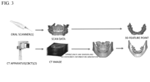
- FIG. 3 is a diagram illustrating a 3D feature point detection process illustrated in FIG. 2 as an image.
- the scan data acquisition unit 11 acquires scan data (S1).
- the scan data acquisition unit 11 may be an oral scanner 1 that acquires scan data by locally scanning the inside of the patient's oral cavity.
- the scan data acquisition unit 11 also wiredly or wirelessly communicates with the oral scanner 1 to receive and acquire the scan data obtained through the oral scanner 1 through wired or wireless communication.
- the scan data may include a plurality of scan frames.
- the CT image acquisition unit 12 which acquires a CT image obtained by capturing the inside of the patient's oral cavity may be, for example, CT apparatus 2.
- the CT image of the inside of the patient's oral cavity captured through the CT apparatus 2 may be provided and acquired from the CT apparatus 2 through the wired and wireless communication.
- the CT apparatus 2 may be, for example, cone beam computed tomography (CBCT) apparatus.
- CBCT cone beam computed tomography
- the 3D coordinate information generation unit 13 generates 3D coordinate information of the CT image acquired by the CT image acquisition unit 12 (S2). For example, the 3D coordinate information generation unit 13 divides the CT image into upper and lower jaws using deep learning, and then generates 3D coordinate information for the upper and lower jaws of the divided CT image, respectively. At this time, the 3D coordinate information may mean a depth map, a 3D point cloud, a 3D mesh, or the like.
- the 3D feature point detection unit 14 detects a 3D feature point for the 3D coordinate information of the CT image generated by the 3D coordinate information generation unit 13 and a 3D feature point for the scan data acquired by the scan data acquisition unit 11 (S3).
- the 3D feature point detection process S3 is illustrated in FIGS. 4 and 5 .
- FIG. 4 is a flowchart illustrating a detailed process of the 3D feature point detection process illustrated in FIG. 2
- FIG. 5 is a diagram illustrating the detailed process of the 3D feature point detection process illustrated in FIG. 4 as the image.
- the 3D feature point detection process S3 is illustrated as below with reference to FIGS. 4 and 5 .
- Rendering is performed in a z-axis direction on the 3D coordinate information of the acquired scan data and the generated CT image to generate a 2D rendered image for the scan data and the CT image (S31).
- adjacent points 3a and 3b (hereinafter, referred to as ⁇ 2D point') between teeth are detected in the 2D rendering images generated from the 3D coordinate information of the scan data and the CT image, respectively in the process S31 (S32).
- the 2D point detection process S32 may be detected by using a deep learning network learning of finding adjacent points between teeth, i.e., 2D points 3a and 3b in the 2D rendering image.
- 3D inter-teeth adjacent points 4a and 4b are detected by using the 2D points 3a and 3b detected in the process S32 (S33).
- the 2D points 3a and 3b detected through deep learning are projected to original 3D data (scan data and CT image) to detect the 3D points 4a and 4b for the scan data and the CT image (S33).
- a 3D point 5a for the scan data and a 3D feature point 5b for the 3D coordinate information of the CT image are detected by using the respective 3D points 4a and 4b detected in the process S33 (S34).
- FIGS. 6 and 7 The process S34 of detecting the 3D feature points 5a and 5b using the 3D points 4a and 4b is illustrated in FIGS. 6 and 7 .
- FIG. 6 is a flowchart illustrating a process of detecting a 3D feature point for 3D coordinate information of a CT image according to the present invention
- FIG. 7 is a diagram illustrating the detection process illustrated in FIG. 6 as the image.
- (a) of FIG. 7 is a diagram illustrating 3D points for the CT image
- (b) of FIG. 7 is a partial enlarged diagram of (a) of FIG. 7
- (c) of FIG. 7 is a cross-sectional view of (b) of FIG. 7
- (d) of FIG. 7 is a diagram illustrating 3D feature points for the CT image.
- a 3D feature point 5b for the 3D coordinate information of the CT image is detected by sampling two adjacent 3D points 4b' and points 6 on the 3D coordinate information of the CT image in a direction perpendicular to the obtained center point cp (S342).
- the processes are repeatedly performed to detect the 3D feature point 5a for the scan data (S343).
- the scan data the direction perpendicular to the virtual straight line passing through two adjacent 3D points is obtained, and then the center point which becomes the center between two adjacent 3D points in the obtained direction perpendicular to the virtual straight line is obtained, and two adjacent 3D points, and the points on the 3D coordinate information of the scan data in the direction perpendicular to the center point are sampled to detect the 3D feature point 5a for the scan data.
- the 3D feature point for the 3D coordinate information of the CT image is detected, and then the 3D feature point for the scan data is detected, but this is an example, and the process of detecting the 3D feature point for the scan data may be performed simultaneously with the process of detecting the 3D feature point for the 3D coordinate information of the CT image, or also performed before the process. In other words, the order is not limited.
- the coordinate matching unit 15 matches coordinates of the scan data and the CT image by using the 3D feature points 5a and 5b detected through the 3D feature point detection unit 14 (S4).
- the coordinates of the scan data and the CT image may be matched with each other by the following method.
- 'C' represents the 3D coordinate information generated from the CT image
- 'D' represents the scan data
- the process of matching the coordinates of the scan data and the CT image is to approximately match the coordinates of the scan data and the CT image by obtaining the approximate rotation matrix R and translation vector t using [Equation 1] above based on the 3D feature point, and matches the coordinates of the scan data and the CT image by using [Equation 1] above with respect to all 3D coordinate information (including the 3D feature point) generated by the CT image and all points (including the 3D feature point) of the scan data again to minimize errors.
- coordinate information of the scan data D is transformed into R ( R 1 D + t 1 ) + t by obtaining the rigid transform R,t of minimizing the error E ( R , t ) by using [Equation 3] below with respect to 3D coordinate information C generated by the CT image and all points R 1 D + t 1 of coordinate-shifted scan data to match the coordinates of the scan data and the CT image.
- E R t C ⁇ R R 1 D + t 1 + t
- FIG. 8 is a diagram illustrating a process in which scan key frames are matched according to the CT image of the present invention as the image.
- the rematching and rigid transform calculation unit 16 matches scan key frames of the scan data initially positioned by the detected 3D feature points, and simultaneously obtains a rigid transform of the scan key frames as in [Equation 4] below so as to minimize a 3D distance between the scan key frames and the CT images (S5).
- the scan key frame is a term used to expand a semantic range of the scan frame.
- the scan key frame may be one scan data or data representing adjacent scan frames.
- the scan data may also be reprojected data.
- the scan key frame is one scan frame and the number of key frames is equal to the total number of frames, this means that all frames are matched, and if it is a frame made by combining several scan frames into one rather than a single frame unit (a result obtained by scanning a predetermined range), this means that frame sets that have already been matched for each section are matched between sets.
- the reprojected data means that scan data that has already been matched once is reprojected toward a camera again to create and use a new frame.
- This method may reduce the accumulated matching errors of the scan frames because the scan frames are matched according to the geometric structure of the CT image.
- a method for obtaining a rigid transform that satisfies this is as follows.
- p i, k represents a point corresponding an i -th scan key frame
- C ( i,j ) represents a set of all points that are shared between an i -th key frame and a j -th key frame
- c i,k represents a point of 3D coordinate information of the CT image corresponding to p i,k
- N i represents the number of points where p i,k and c i , k correspond to each other
- w 1, i - and w 2, i - represent weights corresponding to respective losses.
- each weight may be ⁇ 0'.
- a rigid transform obtained by increasing only w 1, i - decreases a matching error between scan key frames instead of increasing the matching error between the scan key frame and the CT image.
- a rigid transform obtained by increasing only w 2, i - decreases the matching error between the scan key frame and the CT image instead of increasing the matching error between the scan key frames.
- a direction in which a 3D distance between scan key frame data and CT image data corresponding thereto is minimal means that the scan key frame data and the CT image data are close to each other.
- a method for minimizing the 3D distance between the scan key frame data and the CT image data may minimize a 3D difference between coordinates of points p k on the scan key frame and points c k on the CT image corresponding thereto as in [Equation 5] below.
- a value by inner product of a normal vector n k of respective points with respect to a difference for 3D coordinates of respective points of the scan key frame data and the CT image data may also be minimized.
- the normal vector means a normal vector for points on target data to which data is to be moved.
- a difference between depth map points d p k of the scan key frame and depth map points d c k on the CT image may also be minimized.
- the method for minimizing the 3D distance between the scan key frame data and the CT image data may be calculated by various methods.
- FIG. 9 is a diagram illustrating an example of a CT image with metal artifact.
- a tooth including metal in the tooth CT image has severe metal artifact, but a tooth which does not include the metal has almost no artifact.
- CT artifact is severe, a size of w 2, i - is partially decreased or is set to 0, and a size of w 1, i - is increased to reduce an influence of the CT image when matching the scan key frames.
- the matching error between the scan key frames is large, the size of w 1, i - is decreased or is 0, and the size of w 2, i - is increased to increase an influence of the CT image, thereby reducing the matching error between the scan key frames.
- the present invention like the rigid transform obtained in [Equation 4] above, by using a rigid transform considering both a relationship ( w 2, i - part) with the CT image and a relationship ( w 1, i - part) between the scan frames, the 3D coordinate information of the scan frame is corrected and rematched to supplement an artifact problem by emphasizing a matching weight between the scan frames when the artifact of the CT image (an image in which an unnecessary part is captured when capturing the CT image) is severe.
- FIG. 10 is a diagram illustrating a process of matching the 3D feature point of the CT image with each scan data according to the present invention as the image.
- a similarity an inner product of the scan data and the CT image, shift, etc.
- a 3D feature point for the 3D coordinate information of the CT image detected by the 3D feature point detection unit 14 is matched with each scan data to obtain the 3D feature point of the scan data again, and matching may also be performed by the rematching and rigid transform calculation unit 16 by using only the 3D feature point of the scan data obtained again.
- the oral scan model reconstruction unit 17 reconstructs a 3D oral scan model by correcting and matching the existing scan key frames by using the rigid transform obtained through the rematching and rigid transform calculation unit 16 (S6). That is, the oral scan model reconstruction unit 17 reconstructs a 3D oral scan model by rematching 3D coordinate information of an original scan key frame by using the rigid transform obtained through [Equation 4] above through the rematching and rigid transform calculation unit 16.
- the device and the method for reconstructing the 3D oral scan data according to the embodiments of the present invention may be provided as one module or software form in the oral scanner or CT apparatus.
- the oral scanner includes the components of FIG. 1 to reconstruct the 3D oral scan model by receiving the CT image from the CT apparatus
- the CT apparatus includes the components of FIG. 1 to reconstruct the 3D oral scan model by receiving the scan data from the oral scanner.
- the device and the method for reconstructing the 3D oral scan data may be implemented, for example, as a form (or a computer program product) of a recording medium executable by a computer, such as a program module stored in a computer-readable recording medium and executed by the computer.
- the computer-readable recording medium may include computer storage media (e.g., a memory, a hard disk, a magnetic/optical medium, or a slid-state drive (SSD)).
- the computer-readable media may be predetermined available media accessible by the computer and for example, includes all of volatile and non-volatile media and removable and irremovable media.
- the device and the method for reconstructing the 3D oral scan data may include instructions executable in whole or in part by the computer, and the computer program may include programmable machine instructions processed by a processor, and may be implemented by a high-level programming language, an object-oriented programming language, an assembly language, or a machine language.
Landscapes
- Health & Medical Sciences (AREA)
- Engineering & Computer Science (AREA)
- Life Sciences & Earth Sciences (AREA)
- Physics & Mathematics (AREA)
- Medical Informatics (AREA)
- Public Health (AREA)
- Veterinary Medicine (AREA)
- General Health & Medical Sciences (AREA)
- Animal Behavior & Ethology (AREA)
- Optics & Photonics (AREA)
- Theoretical Computer Science (AREA)
- Surgery (AREA)
- Biophysics (AREA)
- Pathology (AREA)
- Nuclear Medicine, Radiotherapy & Molecular Imaging (AREA)
- Biomedical Technology (AREA)
- Heart & Thoracic Surgery (AREA)
- Molecular Biology (AREA)
- Radiology & Medical Imaging (AREA)
- High Energy & Nuclear Physics (AREA)
- Computer Vision & Pattern Recognition (AREA)
- General Physics & Mathematics (AREA)
- Dentistry (AREA)
- Oral & Maxillofacial Surgery (AREA)
- Pulmonology (AREA)
- Epidemiology (AREA)
- Computer Graphics (AREA)
- Apparatus For Radiation Diagnosis (AREA)
- General Engineering & Computer Science (AREA)
- Geometry (AREA)
- Audiology, Speech & Language Pathology (AREA)
Applications Claiming Priority (2)
| Application Number | Priority Date | Filing Date | Title |
|---|---|---|---|
| KR1020220018687A KR102453897B1 (ko) | 2022-02-14 | 2022-02-14 | 컴퓨터 단층촬영 영상을 활용한 3차원 구강 스캔 데이터 복원 장치 및 방법 |
| PCT/KR2022/019837 WO2023153606A1 (ko) | 2022-02-14 | 2022-12-07 | 컴퓨터 단층촬영 영상을 활용한 3차원 구강 스캔 데이터 복원 장치 및 방법 |
Publications (2)
| Publication Number | Publication Date |
|---|---|
| EP4481671A1 true EP4481671A1 (de) | 2024-12-25 |
| EP4481671A4 EP4481671A4 (de) | 2025-06-11 |
Family
ID=83597968
Family Applications (1)
| Application Number | Title | Priority Date | Filing Date |
|---|---|---|---|
| EP22926203.5A Withdrawn EP4481671A4 (de) | 2022-02-14 | 2022-12-07 | Vorrichtung und verfahren zur rekonstruktion dreidimensionaler oraler scan-daten unter verwendung eines computertomografiebildes |
Country Status (5)
| Country | Link |
|---|---|
| US (1) | US20250157061A1 (de) |
| EP (1) | EP4481671A4 (de) |
| KR (1) | KR102453897B1 (de) |
| CN (1) | CN118648025A (de) |
| WO (1) | WO2023153606A1 (de) |
Families Citing this family (3)
| Publication number | Priority date | Publication date | Assignee | Title |
|---|---|---|---|---|
| KR102453897B1 (ko) * | 2022-02-14 | 2022-10-12 | 주식회사 에이치디엑스윌 | 컴퓨터 단층촬영 영상을 활용한 3차원 구강 스캔 데이터 복원 장치 및 방법 |
| KR102703551B1 (ko) * | 2022-05-23 | 2024-09-05 | 주식회사 메가젠임플란트 | 인공지능을 적용한 3차원 얼굴스캔 자동매칭장치 및 그 장치의 구동방법, 그리고 매체에 저장된 컴퓨터프로그램 |
| KR102584812B1 (ko) * | 2023-03-13 | 2023-10-05 | 경상국립대학교산학협력단 | 증강현실을 이용한 치아 삭제 가이드 방법 및 이를 수행하기 위한 장치 |
Family Cites Families (5)
| Publication number | Priority date | Publication date | Assignee | Title |
|---|---|---|---|---|
| US8948482B2 (en) * | 2012-11-01 | 2015-02-03 | Align Technology, Inc. | Motion compensation in a three dimensional scan |
| WO2015142291A1 (en) * | 2014-03-20 | 2015-09-24 | National University Of Singapore | Computer-aided planning of craniomaxillofacial and orthopedic surgery |
| KR102273437B1 (ko) | 2021-01-20 | 2021-07-07 | 주식회사 에이치디엑스윌 | 컴퓨터 단층촬영 영상을 활용한 3차원 구강 스캔 데이터 정합 장치 및 방법 |
| KR102273438B1 (ko) * | 2021-01-27 | 2021-07-07 | 주식회사 에이치디엑스윌 | 구강 스캔 데이터의 크라운 분할을 이용한 구강 스캔 데이터와 컴퓨터 단층촬영 이미지 자동 정합 장치 및 방법 |
| KR102453897B1 (ko) * | 2022-02-14 | 2022-10-12 | 주식회사 에이치디엑스윌 | 컴퓨터 단층촬영 영상을 활용한 3차원 구강 스캔 데이터 복원 장치 및 방법 |
-
2022
- 2022-02-14 KR KR1020220018687A patent/KR102453897B1/ko active Active
- 2022-12-07 EP EP22926203.5A patent/EP4481671A4/de not_active Withdrawn
- 2022-12-07 WO PCT/KR2022/019837 patent/WO2023153606A1/ko not_active Ceased
- 2022-12-07 US US18/838,490 patent/US20250157061A1/en active Pending
- 2022-12-07 CN CN202280091732.9A patent/CN118648025A/zh active Pending
Also Published As
| Publication number | Publication date |
|---|---|
| US20250157061A1 (en) | 2025-05-15 |
| WO2023153606A1 (ko) | 2023-08-17 |
| EP4481671A4 (de) | 2025-06-11 |
| KR102453897B1 (ko) | 2022-10-12 |
| CN118648025A (zh) | 2024-09-13 |
Similar Documents
| Publication | Publication Date | Title |
|---|---|---|
| EP4481671A1 (de) | Vorrichtung und verfahren zur rekonstruktion dreidimensionaler oraler scan-daten unter verwendung eines computertomografiebildes | |
| CN110570492B (zh) | 一种基于神经网络的ct伪影抑制方法、设备以及介质 | |
| US9886748B2 (en) | Alignment of mixed-modality data sets for reduction and removal of imaging artifacts | |
| US12374003B2 (en) | Method of metal artefact reduction in x-ray dental volume tomography | |
| CN1926578B (zh) | 运动补偿 | |
| CN103218803B (zh) | 计算机断层造影设备和用于确定身体的体积信息的方法 | |
| US12115017B2 (en) | Method of calibrating x-ray projection geometry in x-ray cone beam computed tomography | |
| KR102346199B1 (ko) | 파노라믹 영상 생성 방법 및 이를 위한 영상 처리장치 | |
| US20210065414A1 (en) | System and method for sinogram sparsified metal artifact reduction | |
| US12482052B2 (en) | Three-dimensional tooth image display apparatus and method, and method for training three-dimensional tooth image display apparatus | |
| CN115482180A (zh) | 目标区域确定方法和医学成像系统 | |
| US8634620B2 (en) | Method for supplying a 3D X-ray image data record for a moving object with highly absorbent material | |
| EP3272290B1 (de) | Vorrichtung und verfahren zur rekonstruktion eines medizinischen bildes | |
| CN113643394A (zh) | 散射校正方法、装置、计算机设备和存储介质 | |
| EP3629294A1 (de) | Verfahren zum bereitstellen eines trainingsdatensatzes | |
| JP2022521136A (ja) | 歯の骨年齢を決定するための装置、方法及び命令を記録した記録媒体 | |
| CN116309909B (zh) | 一种口腔扫描图像处理方法以及装置 | |
| US12548223B2 (en) | Ultra-fast-pitch acquisition and reconstruction in helical computed tomography | |
| JP2023167122A (ja) | X線ct装置、および、高画質画像生成装置 | |
| US20260000377A1 (en) | Imaging with scatter correction with the aid of noisy scatter estimations and scatter interpolation | |
| US20260030819A1 (en) | Cone beam artifact reduction | |
| JP2006000223A (ja) | X線ct装置 | |
| KR20240137950A (ko) | 다양한 방사성 추적자를 사용한 저화질 pet 영상에 적용가능한 pet 영상 복원 방법 및 장치 | |
| CN119228994A (zh) | 基于改进graf算法的心脏三维重建方法、系统与程序产品 |
Legal Events
| Date | Code | Title | Description |
|---|---|---|---|
| STAA | Information on the status of an ep patent application or granted ep patent |
Free format text: STATUS: THE INTERNATIONAL PUBLICATION HAS BEEN MADE |
|
| PUAI | Public reference made under article 153(3) epc to a published international application that has entered the european phase |
Free format text: ORIGINAL CODE: 0009012 |
|
| STAA | Information on the status of an ep patent application or granted ep patent |
Free format text: STATUS: REQUEST FOR EXAMINATION WAS MADE |
|
| 17P | Request for examination filed |
Effective date: 20240813 |
|
| AK | Designated contracting states |
Kind code of ref document: A1 Designated state(s): AL AT BE BG CH CY CZ DE DK EE ES FI FR GB GR HR HU IE IS IT LI LT LU LV MC ME MK MT NL NO PL PT RO RS SE SI SK SM TR |
|
| DAV | Request for validation of the european patent (deleted) | ||
| DAX | Request for extension of the european patent (deleted) | ||
| A4 | Supplementary search report drawn up and despatched |
Effective date: 20250512 |
|
| RIC1 | Information provided on ipc code assigned before grant |
Ipc: A61C 9/00 20060101ALI20250506BHEP Ipc: A61B 6/51 20240101ALI20250506BHEP Ipc: A61C 7/00 20060101ALI20250506BHEP Ipc: A61B 5/00 20060101ALI20250506BHEP Ipc: A61B 6/03 20060101ALI20250506BHEP Ipc: A61B 6/00 20240101ALI20250506BHEP Ipc: G06T 11/00 20060101ALI20250506BHEP Ipc: G06T 7/73 20170101ALI20250506BHEP Ipc: G06T 7/33 20170101ALI20250506BHEP Ipc: G06T 5/00 20240101AFI20250506BHEP |
|
| STAA | Information on the status of an ep patent application or granted ep patent |
Free format text: STATUS: THE APPLICATION IS DEEMED TO BE WITHDRAWN |
|
| 18D | Application deemed to be withdrawn |
Effective date: 20251202 |