EP4481351A2 - Split bridge circuit force sensor - Google Patents
Split bridge circuit force sensor Download PDFInfo
- Publication number
- EP4481351A2 EP4481351A2 EP24210961.9A EP24210961A EP4481351A2 EP 4481351 A2 EP4481351 A2 EP 4481351A2 EP 24210961 A EP24210961 A EP 24210961A EP 4481351 A2 EP4481351 A2 EP 4481351A2
- Authority
- EP
- European Patent Office
- Prior art keywords
- compression
- tension
- gauge resistor
- gauge
- resistor
- Prior art date
- Legal status (The legal status is an assumption and is not a legal conclusion. Google has not performed a legal analysis and makes no representation as to the accuracy of the status listed.)
- Pending
Links
Images







Classifications
-
- G—PHYSICS
- G01—MEASURING; TESTING
- G01L—MEASURING FORCE, STRESS, TORQUE, WORK, MECHANICAL POWER, MECHANICAL EFFICIENCY, OR FLUID PRESSURE
- G01L1/00—Measuring force or stress, in general
- G01L1/20—Measuring force or stress, in general by measuring variations in ohmic resistance of solid materials or of electrically-conductive fluids; by making use of electrokinetic cells, i.e. liquid-containing cells wherein an electrical potential is produced or varied upon the application of stress
- G01L1/22—Measuring force or stress, in general by measuring variations in ohmic resistance of solid materials or of electrically-conductive fluids; by making use of electrokinetic cells, i.e. liquid-containing cells wherein an electrical potential is produced or varied upon the application of stress using resistance strain gauges
- G01L1/225—Measuring circuits therefor
- G01L1/2262—Measuring circuits therefor involving simple electrical bridges
-
- A—HUMAN NECESSITIES
- A61—MEDICAL OR VETERINARY SCIENCE; HYGIENE
- A61B—DIAGNOSIS; SURGERY; IDENTIFICATION
- A61B34/00—Computer-aided surgery; Manipulators or robots specially adapted for use in surgery
- A61B34/30—Surgical robots
-
- A—HUMAN NECESSITIES
- A61—MEDICAL OR VETERINARY SCIENCE; HYGIENE
- A61B—DIAGNOSIS; SURGERY; IDENTIFICATION
- A61B90/00—Instruments, implements or accessories specially adapted for surgery or diagnosis and not covered by any of the groups A61B1/00 - A61B50/00, e.g. for luxation treatment or for protecting wound edges
- A61B90/06—Measuring instruments not otherwise provided for
-
- G—PHYSICS
- G01—MEASURING; TESTING
- G01L—MEASURING FORCE, STRESS, TORQUE, WORK, MECHANICAL POWER, MECHANICAL EFFICIENCY, OR FLUID PRESSURE
- G01L1/00—Measuring force or stress, in general
- G01L1/20—Measuring force or stress, in general by measuring variations in ohmic resistance of solid materials or of electrically-conductive fluids; by making use of electrokinetic cells, i.e. liquid-containing cells wherein an electrical potential is produced or varied upon the application of stress
- G01L1/22—Measuring force or stress, in general by measuring variations in ohmic resistance of solid materials or of electrically-conductive fluids; by making use of electrokinetic cells, i.e. liquid-containing cells wherein an electrical potential is produced or varied upon the application of stress using resistance strain gauges
- G01L1/2268—Arrangements for correcting or for compensating unwanted effects
- G01L1/2281—Arrangements for correcting or for compensating unwanted effects for temperature variations
-
- G—PHYSICS
- G01—MEASURING; TESTING
- G01L—MEASURING FORCE, STRESS, TORQUE, WORK, MECHANICAL POWER, MECHANICAL EFFICIENCY, OR FLUID PRESSURE
- G01L1/00—Measuring force or stress, in general
- G01L1/20—Measuring force or stress, in general by measuring variations in ohmic resistance of solid materials or of electrically-conductive fluids; by making use of electrokinetic cells, i.e. liquid-containing cells wherein an electrical potential is produced or varied upon the application of stress
- G01L1/22—Measuring force or stress, in general by measuring variations in ohmic resistance of solid materials or of electrically-conductive fluids; by making use of electrokinetic cells, i.e. liquid-containing cells wherein an electrical potential is produced or varied upon the application of stress using resistance strain gauges
- G01L1/2287—Measuring force or stress, in general by measuring variations in ohmic resistance of solid materials or of electrically-conductive fluids; by making use of electrokinetic cells, i.e. liquid-containing cells wherein an electrical potential is produced or varied upon the application of stress using resistance strain gauges constructional details of the strain gauges
-
- G—PHYSICS
- G01—MEASURING; TESTING
- G01L—MEASURING FORCE, STRESS, TORQUE, WORK, MECHANICAL POWER, MECHANICAL EFFICIENCY, OR FLUID PRESSURE
- G01L19/00—Details of, or accessories for, apparatus for measuring steady or quasi-steady pressure of a fluent medium insofar as such details or accessories are not special to particular types of pressure gauges
- G01L19/04—Means for compensating for effects of changes of temperature, i.e. other than electric compensation
-
- G—PHYSICS
- G01—MEASURING; TESTING
- G01L—MEASURING FORCE, STRESS, TORQUE, WORK, MECHANICAL POWER, MECHANICAL EFFICIENCY, OR FLUID PRESSURE
- G01L5/00—Apparatus for, or methods of, measuring force, work, mechanical power, or torque, specially adapted for specific purposes
- G01L5/16—Apparatus for, or methods of, measuring force, work, mechanical power, or torque, specially adapted for specific purposes for measuring several components of force
- G01L5/161—Apparatus for, or methods of, measuring force, work, mechanical power, or torque, specially adapted for specific purposes for measuring several components of force using variations in ohmic resistance
- G01L5/1627—Apparatus for, or methods of, measuring force, work, mechanical power, or torque, specially adapted for specific purposes for measuring several components of force using variations in ohmic resistance of strain gauges
-
- A—HUMAN NECESSITIES
- A61—MEDICAL OR VETERINARY SCIENCE; HYGIENE
- A61B—DIAGNOSIS; SURGERY; IDENTIFICATION
- A61B90/00—Instruments, implements or accessories specially adapted for surgery or diagnosis and not covered by any of the groups A61B1/00 - A61B50/00, e.g. for luxation treatment or for protecting wound edges
- A61B90/06—Measuring instruments not otherwise provided for
- A61B2090/064—Measuring instruments not otherwise provided for for measuring force, pressure or mechanical tension
Definitions
- Force sensing and feedback during a minimally invasive surgical procedure may bring better immersion, realism and intuitiveness to a surgeon performing the procedure.
- force sensors may be placed on a surgical instrument and as close to the anatomical tissue interaction as possible.
- One approach is to embed a force sensor at a distal end of a surgical instrument shaft with electrical strain gauges formed on the force transducer, through printing or additive deposition processes, to measure strain imparted to the surgical instrument.
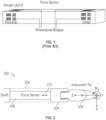
- FIG. 1 is an illustrative drawing representing a force sensor that includes a rectangular beam with four full-Wheatstone bridges (full-bridges).
- a bridge circuit is a circuit topology of electrical circuit in which two circuit branches (usually in parallel with each other) are bridged by a third branch connected between the first two branches at some intermediate point along them.
- Two full-bidges are formed on each of two adjacent orthogonal side faces of the beam to measure forces orthogonal to a longitudinal axis of the beam.
- the beam may be secured to a distal portion of a surgical instrument shaft to sense forces orthogonal to a longitudinal axis of the shaft.
- a forces applied orthogonal to a side face of the beam i.e. an X or Y force
- a force sensor may experience a variety of different strain sources including: the orthogonal force of interest to be measured, moment, off axis force, off axis moment, compression/tension, torsion, ambient temperature and gradient temperature.
- Each of the full-bridges cancels the following stress: temperature, torsion, off axis force, and off axis moment.
- Each individual full-bridge output indicates stress due to force, moment, and compression/tension. The subtraction of an output value produced by a proximal full-bridge formed on a side face from an output value produced by a distal full-bridge on the same side face, cancels the moment and compression/tension, resuling in an output value that represents the orthogonal force of interest to be measured.
- a surgical instrument force sensor may be critical to ensuring patient safety. Accordingly, force sensor error detection may be required to protect against harm by detecting force sensor failures.
- One approach to error detection may be to provide additional full-bridges to produce redundant force measurements that can be compared to detect errors.
- limited space on beam side faces makes formation of additional full-bridges on a side face impractical.
- a manufacturing process typically is limited to formation of bridges at most on two side faces. Formation of bridges on four side facess would increase manufacturing cost significantly.
- a force sensor in one aspect, includes a beam having a longitudinal axis and a proximal end portion and a distal end portion.
- a first Wheatstone bridge is disposed on a first face of the beam and includes first and second tension gauge resistors and first and second compression gauge resistors.
- a second Wheatstone bridge is disposed on the first face of the beam and includes third and fourth tension gauge resistors and third and fourth compression gauge resistors.
- the first and third tension gauge resistors and the first and third compression gauge resistors are disposed at a proximal end portion of the beam.
- the second and fourth tension gauge resistors and the second and fourth compression gauge resistors are disposed at a distal end portion of the beam.
- a force sensor in another aspect, includes a beam having a longitudinal axis and a proximal end portion and a distal end portion.
- a first tension gauge half-bridge is disposed on a first face of the beam and includes first and second tension gauge resistors.
- a second tension gauge half-bridge is disposed on the first face of the beam and includes third and fourth tension gauge resistors.
- a compression gauge half-bridge is disposed on the first face of the beam and includes first and second compression gauge resistors. The first and third tension gauge resistors and the first compression gauge resistor are disposed at a proximal end portion of the beam.
- the second and fourth tension gauge resistors and the second compression gauge resistor are disposed at a distal end portion of the beam.
- a force sensor in yet another aspect, includes a beam having a longitudinal axis and a proximal end portion and a distal end portion.
- a first bridge circuit is disposed on a first face of the beam and includes multiple tension gauge resistors and at least one compression gauge resistor.
- a second bridge circuit is disposed on the first face of the beam and includes multiple tension gauge resistors and at least one compression gauge resistor.
- the at least one tension resistor from each of the first and second bridge circuits and at least one compression gauge resistor from one of the first and second bridges are disposed at a proximal end portion of the beam.
- the at least one tension resistor from each of the first and second bridge circuits and at least one compression gauge resistor from one of the other of the first and second bridges are disposed at a distal end portion of the beam.
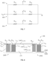
- FIG. 2 is an illustrative side elevation view of a distal portion of a surgical instrument 202 with an elongated shaft 204, shown in partially cut-way, having a force sensor beam 206 mounted thereon, in accordance with some examples.
- the surgical instrument 202 includes an end effector 208, which may include articulatable jaws, for example.
- the end effector 208 contacts anatomical tissue, which may result in X, Y, or Z direction forces and that may result in moment forces such as a moment M Y about a y-direction axis.
- the force sensor 206 which includes a longitudinal axis 210, may be used to measure X and Y forces perpendicular to the longitudinal axis 210.
- FIG. 3 is an illustrative perspective view of a force sensor beam 206 having a beam side face 212 with a pair of split bridge circuits formed thereon.
- the bridge circuits are split in that a portion of each bridge circuit is disposed at a proximal end portion of the beam and a portion of the bridge circuit is disposed at a distal end portion of the beam.
- the bridge circuits are configured as interleaved split full-Wheatstone bridges (full-bridges) formed thereon, having strain gauge resistors R C1 , R C3 , R T1 , R T3 aligned along a neutral axis (equidistant from the sides of the beam) at a proximal beam end portion 206P and having strain gauge resistors R C2 , R C4 , R T2 , R T4 aligned along a neutral axis at a distal beam end portion 206D, in accordance with some examples.
- An identical pair of interleaved split full-bridges (not shown) is formed on an adjacent orthogonal beam side face 214.
- the pair of interleaved split full-bridges formed on adjacent orthogonal side faces are configured to measure forces perpendicular to a longitudinal axis 210 of the beam 206, which may impart tensile strain to the beam. It will be appreciated that alignment of the gauge resistors along the neutral axis reduces the effect of off axis load since the neutral axis is insensitive to off axis force and moments
- Figure 4A is an illustrative schematic diagram representative of a first split full-bridge bridge of the pair, which includes a tension-gauge half-bridge comprising tension strain gauge resistors R T1 and R T2 and includes a compression-gauge half-bridge comprising compression strain gauge resistors R C1 and R C2 , coupled as shown to receive an input voltage V in and to produce a first output voltage V O1 .
- Figure 4B is an illustrative schematic diagram representative of a second split full-bridge of the pair, which includes a tension-gauge half-bridge tension strain gauge resistors R T3 and R T4 and includes a compression-gauge half-bridge comprising compression strain gauge resistors R C3 and R C4 , coupled as shown to receive the input voltage V in and to produce a second output voltage V O2 .
- each tension strain gauge resistor R T1 -R T4 and each compression strain gauge resistor R C1 -R C4 includes a plurality of elongated resistor portions aligned in parallel and coupled end-to-end to form a serpentine or snake-like configuration.
- the elongated portions of the compression strain gauge resistors R C1 -R C4 may be aligned parallel to the longitudinal axis 210 of the beam to sense compression strain upon the beam 206.
- the elongated portions of the tension strain gauge resistors R T1 -R T4 may be aligned perpendicular to the longitudinal axis of the beam to sense tension strain upon the beam.
- each interleaved split full-bridge has a tension gauge sensor resistor and a compression gauge sensor resistor disposed at the proximal end portion 206P of the beam 206.
- Each interleaved split full-bridge also has a tension gauge sensor and a compression gauge sensor disposed at the distal end portion 206D of the beam 206.
- strain gauge resistors, R T1 , P T3 R C1 and R C3 are disposed at the proximal end portion 206P of the beam 206
- strain gauge resistors R T2 , R T4 , R C2 and H C4 are disposed at the distal end portion 206D of the beam 206.
- strain gauge resistor R T1 are interleaved with elongated portions of strain gauge resistor R T3 so as to be co-located and occupy same longitudinal region of the beam.
- Elongated portions of strain gauge resistor R C1 are interleaved with elongated portions of strain gauge resistor R C3 so as to be co-located and occupy same longitudinal region of the beam.
- the interleaved compression gauge resistors R C1 , R C3 are disposed closer to the proximal end of the beam than the interleaved tension resistors R T1 , R T3 .
- Elongated portions of strain gauge resistor R T2 are interleaved with elongated portions of strain gauge resistor R T4 so as to be co-located and occupy same longitudinal region of the beam.
- Elongated portions of strain gauge resistor R C3 are interleaved with elongated portions of strain gauge resistor R C4 so as to be co-located and occupy same longitudinal region of the beam.
- the interleaved compression gauge resistors R C2 , R C4 are disposed farther from the distal end of the beam than the interleaved tension resistors R T2 , R T4 .
- Figure 5 is an illustrative perspective view of a force sensor beam 206 having a beam side face 212 with staggered split full-bridges formed thereon, each having strain gauge resistors R C1 , R C3 , R T1 , R T3 aligned along a neutral axis at a proximal beam end portion 206P and each having strain gauge resistors R C2 , R C4 , R T2 , R T4 aligned along a neutral axis at a distal beam end portion 206D, in accordance with some examples.
- the beam has four elongated rectangular side faces and rectangular end faces.
- An identical pair of staggered split full-bridges (not shown) is formed on an adjacent orthogonal beam side face 214.
- the pair of staggered split full-bridges formed on adjacent orthogonal side faces are configured to measure forces perpendicular to the longitudinal axis of the beam, which may impart tensile strain to the beam.
- Each staggered split full-bridge has a tension gauge sensor resistor and a compression gauge sensor resistor disposed at the proximal end portion 206P of the beam 206.
- Each full-bridge also has a tension gauge sensor and a compression gauge sensor disposed at the distal end portion 206D of the beam 206.
- strain gauge resistors, R T1 , R T3 R C1 and R C3 are disposed at the proximal end portion 206P of the beam 206, and strain gauge resistors R T2 , R T4 , R C2 and R C4 are disposed at the distal end portion 206D of the beam 206.
- the split staggered split bridges of Figure 5 are disposed in a "staggered"' arrangement in which pairs of strain gauges of each full-bridge are disposed adjacent to each other at opposite end portions of the beam.
- Strain gauge resistors R T1 and R C1 of the first staggered split full-bridge are disposed adjacent to each other at the proximal end portion 206P of the beam 206.
- Strain gauge resistors R T3 and R C3 of the second staggered split full-bridge are disposed adjacent to each other at the proximal end portion 206P of the beam 206, offset farther from the proximal end portion 206B than are the strain gauge resistors R T1 and R C1 .
- strain gauge resistors R T2 and R C2 of the first staggered split full-bridge are disposed adjacent to each other at the distal end portion 206D of the beam 206.
- Strain gauge resistors R T4 and R C4 of the second staggered split full-bridge are disposed adjacent to each other at the distal end portion 206D, offset closer to the distal end portion 206D than are the strain gauge resistors R T2 and R C2 .
- Both the interleaved split full-bridge and the staggered split full-bridge produce redundant first and second output voltages V O1 and V O2 .
- the longitudinal distribution of the tension and compression gauge sensor resistors of the pair of interleaved split full-bridges of Figure 3 and the pair of staggered split full-bridges of Figure 5 cancels out and substantially removes noise that may be caused by forces from other sources such as off axis load moments in any of three directions and forces in either of the two orthogonal directions to the force being measured.
- each of the full-bridges of the pair of interleaved split full-bridges and each of the full-bridges of the pair of staggered split full-bridges includes both tension and compression strain gauge resistors configured to substantially cancel the effects of temperature variation.
- these strain gauge resistors in the example of Figure 3 ensures that they measure strain at the same locations of the beam, which ensures that the redundant first output voltage V O1 and second output voltage V O2 have matching values even if there are temperature variations along the length of the beam.
- the distribution of gauge sensor resistors of each full-bridge between proximal and distal end portions of the beam removes the effects of noise resulting from other sources of force and cancel the effects of temperature so that the first and second output signals V O1 and V O2 produce the same redundant value.
- the first and second output signal values V O1 and V O2 may be compared to determine whether they have different values. A determination that V O1 and V O2 have different values provides an indication of an error due to damage to the force sensor, for example.
- Figure 6 is an illustrative perspective view of a force sensor beam 206 having a beam face 212 with a pair of interleaved split half-Wheatstone bridges (half-bridges) each comprising tensile gauge sensor resistors formed at proximal and distal end portions of the beam 206 and having a shared half-bridge comprising compression gauge resistors formed at proximal and distal end portions of the beam, in accordance with some examples.
- a first tensile gauge half-bridge includes strain gauge resistor P T1 at the proximal end portion 206P and includes strain gauge resistor R T2 at the distal end portion 206D.
- a second tensile gauge half-bridge includes strain gauge resistor R T3 at the proximal end portion 206P and includes strain gauge resistor R T4 at the distal end portion 206D.
- the compression gauge half-bridge includes strain gauge resistor R C1 at the proximal end portion and includes strain gauge resistor R C2 at the distal end portion 206D.
- An identical pair of interleaved split half-bridges (not shown) comprising tensile gauge sensor resistors and an identical shared half-bridge (not shown) comprising compression gauge sensor resistors are formed on an adjacent orthogonal beam face 214.
- the pair of interleaved split half-bridges formed on adjacent orthogonal faces are configured to measure forces perpendicular to the longitudinal axis 210 of the beam 206, which may impart tensile strain to the beam.
- the shared compression gauge sensor resistors formed on adjacent orthogonal beam faces are configured to measure forces parallel to the longitudinal axis of the beam, which may impart compression strain to the beam 206.
- Figure 7 is an illustrative schematic diagram representative of three half-bridges.
- a first tension gauge half-bridge 602 includes tension strain gauge resistors R T1 and R T2 aligned along a neutral axis.
- a second tension gauge half-bridge 604 includes tension strain gauge resistors R T3 and R T4 aligned along a neutral axis.
- a compression half-bridge 606 includes compression strain gauge resistors Rci and R C2 aligned along a neutral axis.
- Each of the first and second tension gauge half-bridges 602, 604 and the compression gauge half-bridge 606 is coupled to receive an input voltage V in .
- the first tension gauge half-bridge 602 is coupled to provide a first tension force output V O1 .
- the second tension gauge half-bridge 604 is coupled to provide a second tension force output V O3 .
- the compression gauge half-bridge 606 is coupled to produce a compression force output V O2 .
- Each resistor R T1 -R T4 and R C1 -R C2 includes a plurality of parallel elongated portions aligned in parallel and coupled end-to-end to form a serpentine or snake-like configuration.
- the elongated portions of resistors R C1 -R C2 are aligned parallel to the longitudinal axis 210 of the beam 206 to act as compression gauge sensors.
- the elongated portions of resistors R T1 -R T4 are aligned perpendicular to the longitudinal axis 210 of the beam 206 to act as tension gauge sensors.
- each interleaved split half-bridge has a tension gauge sensor resistor and a shared compression gauge sensor resistor disposed at the proximal end portion 206P of the beam 206.
- Each interleaved split half-bridge also has a tension gauge sensor and a shared compression gauge sensor disposed at the distal portion 206D of the beam 206.
- strain gauge resistors, R T1 , R C1 and R T3 are disposed at the proximal end portion 206P of the beam 206
- strain gauge resistors R T2 , R C2 and R T4 are disposed at the distal end portion 206D of the beam 206.
- Figure 8 is an illustrative side view of the beam, indicated by dashed lines, representing arrangement of the gauge sensors of the interleaved three half-bridges example of Figure 6 .
- the elongated portions Ln of strain gauge resistor R T1 are interleaved with elongated portions L T3 of strain gauge resistor R T3 so as to be co-located and occupy same longitudinal region of the beam
- the interleaved strain gauge resistors R T1 and R T3 are farther from the proximal end of the beam than is the compression gauge resistor R C1 .
- Lead T1,T2 which extends between the proximal and distal end portions, couples R T1 located at the proximal end portion 206P with R T2 located at the distal end portion 206D.
- Elongated portions L T2 of strain gauge resistor R T2 are interleaved with elongated portions L T4 of strain gauge resistor R T4 so as to be co-located and occupy same longitudinal region of the beam.
- the interleaved strain gauge resistors R T2 and R T4 are disposed closer to the distal end of the beam than is the compression gauge resistor R C2 .
- Lead T3,T4 which extends between the proximal and distal end portions, couples R T3 located at the proximal end portion 206P with R T4 located at the distal end portion 206D.
- Lead C1,C2 which extends between the proximal and distal end portions, couples Rci located at the proximal end portion 206P with R c2 located at the distal end portion 206D.
- Figure 9 is an illustrative perspective view of a force sensor beam 206 having a beam face 212 with a pair of staggered split half-bridges each comprising tension gauge sensor resistors formed at proximal and distal end portions of the beam and having a shared half-bridge comprising compression gauge resistors formed at proximal and distal end portions of the beam, in accordance with some examples.
- the schematic diagram of Figure 7 also is representative of staggered three half-bridges of Figure 9 .
- a first tensile gauge half-bridge includes strain gauge resistor R T1 at the proximal end portion 206P and includes strain gauge resistor R T2 at the distal end portion 206D.
- a second tensile gauge half-bridge includes strain gauge resistor R T3 at the proximal end portion 206P and includes strain gauge resistor R T4 at the distal end portion 206D.
- the compression gauge half-bridge includes strain gauge resistor R C1 at the proximal end portion and includes strain gauge resistor R C2 at the distal end portion 206D.
- An identical pair of interleaved split half-bridges (not shown) comprising tensile gauge sensor resistors and an identical shared half-bridge (not shown) comprising compression gauge sensor resistors are formed on an adjacent orthogonal beam face 214.
- the pair of interleaved split half-bridges formed on adjacent orthogonal faces are configured to measure forces perpendicular to the longitudinal axis 2 10of the beam 206, which may impart tensile strain to the beam 206.
- the shared compression gauge sensor resistors formed on adjacent orthogonal beam faces are configured to measure forces parallel to the longitudinal axis 210 of the beam, which may impart compression strain to the beam 206.
- Figure 10 is an illustrative side view representing arrangement of the gauge sensors of the staggered three half-bridges example of Figure 9 .
- a first tension gauge resistor half-bridge includes tension strain gauge resistors, Rn and R T2 aligned along a neutral axis.
- a second tension gauge resistor half-bridge includes tension strain gauge resistors, R T3 and R T4 aligned along a neutral axis.
- a compression gauge resistor half-bridge includes compression strain gauge resistors R C1 and R C2 aligned along a neutral axis.
- a first compression gauge resistor R C1 is disposed at a proximal end portion of the beam between first and third tension gauge resistors R T1 , R T3 , with the first tension gauge resistor R T1 disposed closer to the proximal end of the beam than the third tension gauge resistor R T3 .
- a second compression gauge resistor R C2 is disposed at a distal end portion of the beam between second and fourth tension gauge resistors R T2 , R T4 , with the fourth tension gauge resistor R T4 disposed closer to the distal end of the beam than the second tension gauge resistor R T2 .
- Lead T1,T2 which extends between the proximal and distal end portions, couples R T1 located at the proximal end portion 206P with R T2 located at the distal end portion 206D.
- Lead T3,T4 which extends between the proximal and distal end portions, couples R T3 located at the proximal end portion 206P with R T4 located at the distal end portion 206D.
- Lead C1,C2 which extends between the proximal and distal end portions, couples R C1 located at the proximal end portion 206P with R c2 located at the distal end portion 206D.
- both the interleaved split half-bridge and the staggered split half-bridge produce redundant first and second tension force output voltages V O1 and V O3 .
- the longitudinal distribution of the tension and compression gauge sensor resistors of the pair of interleaved split half-bridges of Figure 6 and the pair of staggered split half-bridges of Figure 9 cancels out and substantially removes noise that may be caused by forces from other sources such as off axis load moments in any of three directions and forces in either of the two orthogonal directions to the force being measured.
- the interleaving of the strain gauge resistors ensures that they measure strain at the same locations of the beam, which ensures that the redundant first output voltage V O1 and third output voltage V O3 have matching values even if there are temperature variations along the length of the beam.
- each half-bridge both tension gauge half-bridges and compression gauge half-bridge cancels the following stresses: moment, off axis force, off axis moment, compression/tension, torsion, and ambient temperature.
- each individual half-bridge output includes the following: force and gradient temperature.
- ⁇ p and ⁇ d represent the proximate stress and the distal stress and GF represents the gauge factor.
- Vo1 is the output of the half-bridges of 'T gauges' and Vo2 is the output of the half-bridge of 'C gauges', then the subtraction in Vo1 - Vo2 cancels ambient temperature and gradient temperature and the final output after subtraction is only the sought after 'Force'
- the redundant comparison is done after extracting the force signal and temperature differential signal from the half-bridge measurements V O1 , V O2 and V O3 .
- the distribution of gauge sensor resistors of each tension gauge half-bridge between proximal and distal end portions of the beam removes the effects of noise resulting from other sources of force and cancel the effects of temperature so that the first and second tension gauge force output signals V O1 and V O3 produce the same redundant value.
- the first and second tension gauge force output signal values VO1 and V O3 may be compared to determine whether they have different values. A determination that V O1 and V O3 have different values provides an indication of an error due to damage to the force sensor, for example.
- Redundant temperature values are provided by the compression output values V O2 produced by the compression gauge half-bridges formed adjacent orthogonal faces.
- the compression output values V O2 produced by the half-bridges formed adjacent orthogonal faces may be compared to determine whether they have different values. A determination that the compression gauge half-bridges on adjacent orthogonal faces have different values provides an indication of an error due to damage to the force sensor, for example.
- Figure 14 is an illustrative side view of a force applied to a cantilever beam indicating strain measurement at a distance l from the location where force is applied to the beam.
- the difference in distance is a known quantity; it is the distance between the two sensing points.
- Figure 16 is a side view of a cantilever beam.
- strain source that is not compensated is temperature change.
- the most trivial way to compensate for temperature is to use Wheatstone bridge configuration using 'C' (compression) and 'T' (tension) gauges to locally eliminate strain from temperature change.
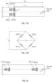
- Figure 17A is a side view of a beam with a Wheatstone bridge disposed at a proximal end thereof.
- Figure 17B is a schematic diagram of the Wheatstone bridge circuit of Figure 17A .
- V out R 1 R 1 + R 2 ⁇ R 4 R 3 + R 4 V in
- V out GF ⁇ V in 4 ⁇ 2 - ⁇ 1 - ⁇ 3 - ⁇ 4
- V out K ⁇ F ⁇ l
- FIG. 18 is a side view of a beam with a split Wheatstone bridge having a tension gauge resistor R1 and a compression gauge resistor R2 disposed along a neutral axis at a proximal end portion thereof and having a tension gauge resistor R3 and a compression gauge resistor R4 disposed along a neutral axis at a distal end portion thereof.
- the schematic diagram of Figure 17B is applicable to the split bridge of Figure 18 .
- the temperature change seen at each measuring point can be decomposed into ambient temperature change which is same everywhere and temperature difference which is temperature delta between the ambient temperature and the temperature at the point.
- the ambient temperature change ends up being a common mode and just the act of subtracting the proximal and distal signal eliminates its effects.
- V out GF ⁇ V in 4 ⁇ 1 - ⁇ 2 ⁇ ⁇ 3 ⁇ ⁇ 4
- Figure 19 is an illustrative drawing representing a force sensor 1900 that includes a beam 1902 with two split full bridge circuits thereon.
- the beam 1902 includes a proximal end portion 1902P and a distal end portion 1902D and a center portion therebetween.
- a first split bridge ciruit includes strain gauge resistors R C1 , R C3 , R T1 , R T3 .
- the first bridge circuit is split, with compression strain gauge resistor R C1 and tension gauge resistor R T1 located at a proximal end portion of the beam and compression strain gauge resistor R C3 and tension gauge resistor R T3 located at a distal end portion of the beam, R T3 .
- a second split bridge ciruit includes strain gauge resistors R C2 , R C4 , R T2 , R T4 .
- the second bridge circuit is split, with compression strain gauge resistor R C2 and tension gauge resistor R T2 located at a proximal end portion of the beam and compression strain gauge resistor R C4 and tension gauge resistor R T4 located at a distal end portion of the beam.
- Measurement output lead line L1 is disposed to extend integral with the proximal, center and distal portions of the beam to electrically couple R T1 and R T3 at a node V O1" .
- Measurement output lead line L2 is disposed to extend integral with the proximal, center and distal portions of the beam to electrically couple Rci and R C3 at a node V O1 + .
- Measurement output lead line L3 is disposed to extend integral with the beam to electrically couple R C2 and R C4 at a node V O2 + .
- Measurement output lead line L4 is disposed to extend integral with the beam to electrically couple R T2 and R T4 at a node V O2 - .
- Input signal lead line L5 extends within the proximal portion of the beam to electrically couple R C1 , R C2 , R T1 and R T2 at a node V I + .
- Input signal lead line L6 extends within the distal portion of the beam to electrically couple R C3 , R C4 , R T3 and R T4 at a node V I - .
- the lead lines L1-L6 are disposed integral with and mechanically coupled to the beam.
- Input tap nodes V I + coupled to R T1 , R T3 , Rci, R C3 , and V I - , coupled to R T2 , R T4 , R C2 , R C4 act as input signal nodes that are coupled to receive positive and negative polarities of an input excitation signal.
- Measurement tap nodes V O1 - and V O1 + at the respective junction of R T1 , R T3 and the junction of R C1 , R C1 act as output measurement signal nodes that are coupled to provide output measurement signals indicative of strain.
- measurement tap nodes V O2 - and V O2 + at the respective junction of R T2 , R T4 and the junction of R C2 , R C4 act as output measurement signal nodes that are coupled to provide output measurement signals indicative of strain.
- each split bridge includes both strain gauge resistors disposed at a proximal end portion of the beam and strain gauge resistors disposed at a distal end portion of the beam, the lead lines L1-L6 that electrically couple the resistors of each bridge are relatively long.
- lead lines that couple the resistors of the first and second split bridges of Figure 19 are relatively longer than lead lines used to couple resistors of the non-split bridge circuits of the illustrative bridge of Figure 1 in which each bridge is located either entirely at a proximal end portion of the beam or at a distal end portion of the beam.
- a split bridge circuit can introduce undesirable amounts of unbalanced lead resistance between the strain gauges because the gauges are distributed at beam location across large distances relative to the size of the strain gauges.
- the lead resistance can affect the accuracy of the sensor measurements and introduce cross coupling and temperature dependent offset.
- the conductive lead lines are integrally formed upon the beam through deposition and etching process that produce the strain gauges.
- the lead lines do not change electrical properties in response to forces imparted to a beam or to a change in temperature, for example.
- the conductive lead lines extending along the beam to couple the active resistive strain gauges at opposite end portions of the beam are subjected to strain as the beam deflects in response to force imparted to the beam, which changes the resistance of the conductive lines.
- the length of the lead lines may be comparable in magnitude to the overall length of the conductor line portions that make up the of the serpentine-shaped resistive strain gauge elements.
- a change in resistance of the electrical conduction lines can result in distortion of strain measurements since the electrical connection lines are not intended as behave as active resistive elements of the bridge circuits. Thus, there is a need to reduce lead resistances and balances what minimal lead resistance remains left over.
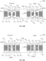
- Figure 20A-20B are is illustrative drawing representing an example force sensor 2000 that includes a beam 2002 having a neutral axis 2004 and that includes two split full bridge circuits with split bridge halves electically coupled by measurement output lead lines L1 '-L4' and electrically coupled input lead lines L5-L6 are mechanically isolated from the the beam 2002.
- Figure 20A illustrates the strain gauge elements R C1 -R C4 and R T1 -R T4 of split bridge halves in simplified block diagram form, and shows mechanically isolated measurement output lead lines L1'-L4' extending between the strain gauge elements of the split bridge halves and shows input signal lead line L5' electrically coupling Rci, R C2 , R T1 and R T2 at a node V I + and shows input signal lead line L6' electrically coupling R C3 , R C4 , R T3 and R T4 at a node V I - .
- Figure 20B illustrates details of a first example arrangement of the strain gauge elements R C1 -R C4 and R T1 -R T4 of the example sensor of Figure 20A .
- Figure 20C illustrates details of a second example arrangement of the strain gauge elements R C1 -R C4 and R T1 -R T4 of the example sensor 2000 of Figure 20A .
- the mechanically isolated measurement output lead lines L1'-L4' and input lead lines L5-L6 are omitted from Figures 20B-20C , although their interconnections are explained below.
- mechanically isolated measurement output lead lines L1'-L4' of Figure 20A correspond to correspondingly labeled integral measurement output lead lines L1-L4 of Figure 19 .
- the mechanically isolated lead lines L1'-L4' are routed externally off the beam, one example of this implementation is to have the leads L1' - L6' be part of a flex circuit/cable that is wirebonded to the beam.
- the flex cable will be mounted such that it has enough slack that the deflection of the beam due to force applied doesn't produce any strain the flex circuit/cable, moreover the lead lines on the flex circuit can be made of lower resistance electrical material, such as Copper in comparison to the higher resistance thin film material, such as Nichrome (an alloy of Nickel and Chromium), thus providing a lowerer magnitude the lead resistances.
- the lead lines L1'-L4' that electrically couple the strain gauge elements are mechanically isolated from strain imparted during deflection of the beam 2002 due to a deflecting force (not shown) applied to the beam.
- Elongated measurement output lead lines L1'-L4' and input lead lines L5-L6 are mechanically isolated from the beam and shorter integral proximal lead line segments X P1 - X P6 and shorter integral distal lead line segments X D1 -X D6 are disposed integral with the beam.
- less stress is imparted to the leads during mechanical deflection of the beam, and therefore, less strain measuremnt distortion is incurred when compared with the example sensor of Figure 19 .
- Mechanically isolated lead line L1' is disposed to extend in mechanical isolation from the beam between the proximal, center and distal portions of the beam, to electrically couple F C1 and R C3 at nodes labeled V O1 - in the proximal and distal bridge halves.
- Isolated lead line L2' is disposed to extend in mechanical isolation from the beam between the proximal, center and distal portions of the beam, to electrically couple R T1 and R T3 at nodes labeled V O1 + in the proximal and distal bridge halves.
- Isolated lead line L3' is disposed to extend in mechanical isolation from the beam between the proximal, center and distal portions of the beam, to electrically couple R C2 and F C4 at nodes labeled V O2 - in the proximal and distal bridge halves.
- Isolated lead line L4' is disposed to extend in mechanical isolation from the beam between the proximal, center and distal portions of the beam, to electrically couple R T2 and R T4 at nodes labeled V O2 + in the proximal and distal bridge halves.
- Proximal lead line elements X P3 -X P4 are coupled to voltage V I + to thereby electrically couple R C1 , R C2 , R T1 and R T2 at the voltage V I + .
- Distal lead line elements X D3 -X D4 are coupled to voltage V I - to thereby electrically couple R C3 , R C4 , R T3 and R T4 to the voltage W I + .
- each of the compression gauge resistors and each of the tension gauge resitors is arranged symmetrically about the neutral axis 2004 of the beam.
- R C1 and R T1 of the proximal half of the first bridge and R C2 and R T2 of the proximal half of the second bridge are arranged symmetrically about a proximal transverse axis 2006P between them at the proximal portion of the beam.
- R T1 partiality surrounds R C1
- R T2 partially surrounds RC 2 .
- Terminals of R C1 and R T1 are transversly aligned proximate to the proximal transverse axis 2006P, and terminals of R C2 and R T2 are transversly aligned distal to the proximal transverse axis 2006P.
- R C3 and R T3 of the distal half of the first bridge and R C4 and R T4 of the distal half of the second bridge are further arranged symmetrically about a distal transverse axis 2006D between them at the distal portion of the beam.
- Terminals of R C3 and R T3 are transversly aligned proximate to the distal transverse axis 2006D, and terminals of R C4 and R T4 are transversly aligned distal to the distal transverse axis 2006D.
- R C3 partiality surrounds R C3
- R T4 partially surrounds R C4 .
- elongated lead line segments L1'-L4' are mechanically isolated from the beam and shorter integral proximal lead line segments X P7 -X P8 and shorter integral distal lead line segments X D7 -X DS are disposed integral with the beam.
- less stress is imparted to the leads during mechanical deflection of the beam, and therefore, less strain measuremnt distortion is incurred when compared with the example sensor of Figure 19 .
- mechanically isolated lead line L1' is disposed to extend in mechanical isolation from the beam between the proximal, center and distal portions of the beam, to electrically couple Rci and R C3 at nodes labeled V O1 - in the proximal and distal bridge halves.
- Isolated lead line L2' is disposed to extend in mechanical isolation from the beam between the proximal, center and distal portions of the beam, to electrically couple R T1 and R T3 at nodes labeled V O1 + in the proximal and distal bridge halves.
- Isolated lead line L3' is disposed to extend in mechanical isolation from the beam between the proximal, center and distal portions of the beam, to electrically couple R C2 and R C4 at nodes labeled V O2 - in the proximal and distal bridge halves.
- Isolated lead line L4' is disposed to extend in mechanical isolation from the beam between the proximal, center and distal portions of the beam, to electrically couple R T2 and R T4 at nodes labeled V O2 + in the proximal and distal bridge halves.
- Proximal lead line elements X P7 -X P8 are coupled to voltage V I + to thereby electrically couple Rci, R C2 , R T1 and R T2 at the voltage V I +
- Distal lead line elements X D7 -X D8 are coupled to voltage V I - to thereby electrically couple R C3 , R C4 , R T3 and R T4 to the voltage V I + .
- Figure 21 is an illustrative drawing showing a set of proximal connection pads 2110P and a set of distal connection pads 2110D disposed upon the beam 2002 of Figure 20A in which input pads 2112 and measurement pads 2114 have matching areas.
- the set of proximal connection pads 2110 and the set of distal connection pads 2110 are disposed upon an example beam 2002 for electrical coupling of mechanically isolated measurement output lead lines L1'-L4' and input signal lines L5'-L6' to the strain gauge resistors. Wire bonds (they are there in figure 21 it is the small arc going from the pads to the collection of lead lines.
- L5-L6 to bundle of leads
- Input signal pads 2112 are coupled to receive the excitation voltage V I + , V I - , as shown.
- Measurement output pads 2114 are coupled to receive the sensed output voltages V O1 - , V O1 + , V O2 - , V O2 + , as shown.
- all pads typically are the same area, and therefore, have the same resistance.
- the wire bonds can be variable, however, which can impact the resistance of the electrical connection between the pads and the leads, which in turn, can influence zero offset between signals on the different electrical leads and also may influence temperature sensitivity of the electrical connection.
- Increased resistance at the input pads affects gain of the voltage, which is related to sensitivity of measurement.
- Increased resistance at the output measurement pads affects the zero offset. In general, gain can be more easily managed than zero offset, using software, for example.
- Figure 22 is an illustrative drawing showing a set of proximal connection pads 2.110P' and a set of distal connection pads 2110D'in which measurement output pads 2114' have larger area than input signal pads 2112'. Input pad area is sacrificed to provide larger measurement pad area. The larger measurement pad area results in reduced resistance of the measurement pads 2114', which reduces the impact of wire bond variation upon connection pad resistance, which in turn, reduces the impact of wire bond variation upon zero offset.
- a relative increase in measurement pad size compared with input signal pad size reduces variability of measurement pad resistance reducing the impact of variation in location and size of a wire bond upon measurement accuracy.
- the set of proximal connection pads 2110P' and the set of distal connection pads 2110D' are disposed upon an example beam 2002 for electrical coupling of mechanically isolated lead lines L1'-L4' and L5'-L6' to strain gauge resistors. Wire bonds electrically couple the leads L1'-L4' to the measurement output pads 2114'.
- Input signal pads 2112' are coupled to receive the excitation voltage V I + , V I - , as shown.
- Measurement signal output pads 2114' are coupled to receive the sensed output voltages V O1 - , V O1 + , V O2 - , V O2 + , as shown.
- Figure 23 is an illustrative circuit schematic showing a force sensor 2000 that includes example first and second split bridge circuits 2310, 2320 disposed upon a beam that share excitation voltage inputs V I + , V I - .
- Half of each bridge circuit is disposed at a proximal end portion of the beam, and half of each bridge circuit is disposed at a distal portion of the beam.
- Figure 23 does not show the physical separation of the proximal and distal halves at opposite end portions of the beam.
- Figure 23 shows the example arrangement of the first and second split bridge circuits at non-overlapping separate locations upon the beam.
- Figure 5 shows an example staggered arrangement of the first and second split bridge circuits.
- Figure 6 shows an example interleaved arrangement of the first and second split bridge circuits.
- measurement redundancy is achieved using two split bridge circuits, each having a half-bridge disposed at the proximal end portion of the beam and having a half-bridge portion disposed at the distal end portion of the beam.
- a mismatch of corresponding output measurements of the two split bridge circuits is indicative of measurement error and possible damage of one or both of the two bridge circuits.
- the resistance of corresponding tap lead lines for first and second bridge circuits should match.
- FIG 24 is an illustrative drawing representing the tap lead lines for the example dual split bridge circuit of Figure 23 .
- Tap lead lines between a voltage level and a circuit node have equal lead line lengths and have uniform line widths to provide matching resistance between a given tap point and each of the circuit nodes electrically coupled to the tap point. Thus, resistances between each tap point and the nodes electrically coupled to the tap point is balanced.
- the tap lead line length and lead line width between tap point of excitation input voltage V I + and the circuit node receiving V I +A equals the tap lead line length and lead line width between tap point of voltage V I + and circuit node receiving V I +B as indicated by the single hash marks on either side of the V I + tap point.
- the tap lead line length and lead line width between tap point of excitation input voltage V I - and the circuit node receiving V I -A equals the tap lead line length and lead line width between tap point of voltage V I - and circuit node receiving V I -B as indicated by the double hash marks on either side of the V I - tap point.
- the tap lead line length and lead line width between tap point of measurement voltage V O1 + and the circuit node providing V O1 +A equals the tap lead line length and lead line width between tap point of voltage V O1 + and circuit node receiving V O1 +B as indicated by the three hash marks on either side of the V O1 + tap point.
- the tap lead line length and lead line width between tap point of measurement voltage V O1 - and the circuit node providing V O1 -A equals the tap lead line length and lead line width between tap point of voltage V O1 - and circuit node receiving V O1 -B as indicated by the four hash marks on either side of the V O1 - tap point.
- the tap lead line length and lead line width between tap point of measurement voltage V O2 + and the circuit node providing V O2 +A equals the tap lead line length and lead line width between tap point of voltage V O2 + and circuit node receiving V O2 +B as indicated by the five hash marks on either side of the V O2 + tap point.
- the tap lead line length and lead line width between tap point of measurement voltage V O2 - and the circuit node providing V O2 -A equals the tap lead line length and lead line width between tap point of voltage V O2 - and circuit node receiving V O2 -B as indicated by the five hash marks on either side of the V O2 - tap point.
- the equal tap lead line length ensures balanced tap line lead length resistance on each side of each tap point resulting in more accurate determinations of circuit damage based upon measurement output signal mismatches, for example.
Landscapes
- General Physics & Mathematics (AREA)
- Physics & Mathematics (AREA)
- Health & Medical Sciences (AREA)
- Life Sciences & Earth Sciences (AREA)
- Surgery (AREA)
- Engineering & Computer Science (AREA)
- Public Health (AREA)
- Veterinary Medicine (AREA)
- Medical Informatics (AREA)
- Molecular Biology (AREA)
- Animal Behavior & Ethology (AREA)
- General Health & Medical Sciences (AREA)
- Biomedical Technology (AREA)
- Heart & Thoracic Surgery (AREA)
- Nuclear Medicine, Radiotherapy & Molecular Imaging (AREA)
- Oral & Maxillofacial Surgery (AREA)
- Pathology (AREA)
- Robotics (AREA)
- Force Measurement Appropriate To Specific Purposes (AREA)
- Measurement Of Force In General (AREA)
Abstract
Description
- This application claims the benefit of priority to
U.S. Provisional Patent Application Serial No. 62/586,721, filed on November 15, 2017 U.S. Provisional Patent Application Serial No. 62/586,166, filed on November 14, 2017 - Force sensing and feedback during a minimally invasive surgical procedure may bring better immersion, realism and intuitiveness to a surgeon performing the procedure. For the best performance of haptics rendering and accuracy, force sensors may be placed on a surgical instrument and as close to the anatomical tissue interaction as possible. One approach is to embed a force sensor at a distal end of a surgical instrument shaft with electrical strain gauges formed on the force transducer, through printing or additive deposition processes, to measure strain imparted to the surgical instrument.
-
Figure 1 is an illustrative drawing representing a force sensor that includes a rectangular beam with four full-Wheatstone bridges (full-bridges). A bridge circuit is a circuit topology of electrical circuit in which two circuit branches (usually in parallel with each other) are bridged by a third branch connected between the first two branches at some intermediate point along them. Two full-bidges are formed on each of two adjacent orthogonal side faces of the beam to measure forces orthogonal to a longitudinal axis of the beam. The beam may be secured to a distal portion of a surgical instrument shaft to sense forces orthogonal to a longitudinal axis of the shaft. A forces applied orthogonal to a side face of the beam (i.e. an X or Y force) is determined by subtracting force measurements determined by the full-bridges at proximal and distal end portions of that side face of the beam. - A force sensor may experience a variety of different strain sources including: the orthogonal force of interest to be measured, moment, off axis force, off axis moment, compression/tension, torsion, ambient temperature and gradient temperature. Each of the full-bridges cancels the following stress: temperature, torsion, off axis force, and off axis moment. Each individual full-bridge output indicates stress due to force, moment, and compression/tension. The subtraction of an output value produced by a proximal full-bridge formed on a side face from an output value produced by a distal full-bridge on the same side face, cancels the moment and compression/tension, resuling in an output value that represents the orthogonal force of interest to be measured.
- A surgical instrument force sensor may be critical to ensuring patient safety. Accordingly, force sensor error detection may be required to protect against harm by detecting force sensor failures. One approach to error detection may be to provide additional full-bridges to produce redundant force measurements that can be compared to detect errors. However, limited space on beam side faces makes formation of additional full-bridges on a side face impractical. Moreover, a manufacturing process typically is limited to formation of bridges at most on two side faces. Formation of bridges on four side facess would increase manufacturing cost significantly.
- In one aspect, a force sensor includes a beam having a longitudinal axis and a proximal end portion and a distal end portion. A first Wheatstone bridge is disposed on a first face of the beam and includes first and second tension gauge resistors and first and second compression gauge resistors. A second Wheatstone bridge is disposed on the first face of the beam and includes third and fourth tension gauge resistors and third and fourth compression gauge resistors. The first and third tension gauge resistors and the first and third compression gauge resistors are disposed at a proximal end portion of the beam. The second and fourth tension gauge resistors and the second and fourth compression gauge resistors are disposed at a distal end portion of the beam.
- In another aspect, a force sensor includes a beam having a longitudinal axis and a proximal end portion and a distal end portion. A first tension gauge half-bridge is disposed on a first face of the beam and includes first and second tension gauge resistors. A second tension gauge half-bridge is disposed on the first face of the beam and includes third and fourth tension gauge resistors. A compression gauge half-bridge is disposed on the first face of the beam and includes first and second compression gauge resistors. The first and third tension gauge resistors and the first compression gauge resistor are disposed at a proximal end portion of the beam. The second and fourth tension gauge resistors and the second compression gauge resistor are disposed at a distal end portion of the beam.
- In yet another aspect, a force sensor includes a beam having a longitudinal axis and a proximal end portion and a distal end portion. A first bridge circuit is disposed on a first face of the beam and includes multiple tension gauge resistors and at least one compression gauge resistor. A second bridge circuit is disposed on the first face of the beam and includes multiple tension gauge resistors and at least one compression gauge resistor. The at least one tension resistor from each of the first and second bridge circuits and at least one compression gauge resistor from one of the first and second bridges are disposed at a proximal end portion of the beam. The at least one tension resistor from each of the first and second bridge circuits and at least one compression gauge resistor from one of the other of the first and second bridges are disposed at a distal end portion of the beam.
- In the drawings, which are not necessarily drawn to scale, like numerals may describe similar components in different views. Like numerals having different letter suffixes may represent different instances of similar components. The drawings illustrate generally, by way of example, but not by way of limitation, various embodiments discussed in the present document.
-
Figure 1 is an illustrative drawing representing a force sensor that includes a rectangular beam with four full-Wheatstone bridges (full-bridges). -
Figure 2 is an illustrative side elevation view of a distal portion of a surgical instrument with an elongated shaft having a force sensor beam mounted thereon, in accordance with some examples. -
Figure 3 is an illustrative perspective view of a force sensor beam having a beam side face with a pair of split bridge circuits formed thereon. -
Figure 4A is an illustrative schematic diagram representative of a first full-bridge bridge circuit. -
Figure 4B is an illustrative schematic diagram representative of a second full-bridge circuit. -
Figure 5 is an illustrative perspective view of a force sensor beam having a beam side face with a pair of staggered split bridge circuits formed thereon. -
Figure 6 is an illustrative perspective view of a force sensor beam having a beam face side with a pair of interleaved split half- bridge circuits. -
Figure 7 is an illustrative schematic diagram representative of three half-bridge circuits. -
Figure 8 is an illustrative side view of the beam showing arrangement of the gauge sensors of the interleaved three half-bridges example ofFigure 6 . -
Figure 9 is an illustrative perspective view of a force sensor beam having a beam face with a pair of staggered split half-bridge circuits. -
Figure 10 is an illustrative side view representing arrangement of the gauge sensors of the staggered three half-bridges example ofFigure 9 . -
Figure 11 is an illustrative perspective view of a beam with a T-gauge (tension) and C gauge (compression) disposed along a neutral axis of a beam. -
Figure 12 is an illustrative perspective view of a beam with tension gauges R1 and R2 disposed along a neutral axis of a beam, respectively, at a proximal end portion and at a distal end portion of the beam. -
Figure 13 is an illustrative schematic diagram representing a half-bridge circuit containing R1 and R2 ofFigure 12 . -
Figure 14 is an illustrative side view of a force applied to a cantilever beam indicating strain measurement at a distance l from the location where force is applied to the beam. -
Figure 15 is an illustrative side view of a force applied to a cantilever beam indicating strain measurement at a proximal distance and at a distal distance from the location where force is applied to the beam. -
Figure 16 is a side view of a cantilever beam. -
Figure 17A is a side view of a beam with a Wheatstone bridge disposed at a proximal end thereof. -
Figure 17B is a schematic diagram of the Wheatstone bridge circuit ofFigure 17A . -
Figure 18 is a side view of a beam with a split Wheatstone bridge having a tension gauge resistor R1 and a compression gauge resistor R2. -
Figure 19 is an illustrative drawing representing an example force sensor that includes a beam with two split full bridge circuits thereon. -
Figure 20A is an illustrative simplified block diagram showing mechanically isolated lead lines extending between strain gauge elements of two proximal split bridge circuit halves and strain gauge elements of two distal split bridge circuit halves. -
Figure 20B is an illustrative drawing showing certain details of a first example arrangement of the strain gauge elements of the example sensor ofFigure 20A . -
Figure 20C is an illustrative drawing showing certain details of a second example arrangement of the strain gauge elements of the example sensor ofFigure 20A . -
Figure 21 is an illustrative drawing showing a set of proximal connection pads and a set of distal connection pads in which input pads and measurement pads have matching areas. -
Figure 22 is an illustrative drawing showing a set of proximal connection pads and a set of distal connection pads in which measurement pads have larger area than input pads. -
Figure 23 is an illustrative circuit schematic showing a force sensor that includes example first and second split bridge circuits disposed upon a beam that share excitation voltage inputs. -
Figure 24 is an illustrative drawing representing the tap lead lines for the example dual split bridge circuit ofFigure 23 . -
Figure 2 is an illustrative side elevation view of a distal portion of asurgical instrument 202 with anelongated shaft 204, shown in partially cut-way, having aforce sensor beam 206 mounted thereon, in accordance with some examples. Thesurgical instrument 202 includes anend effector 208, which may include articulatable jaws, for example. During a surgical procedure, theend effector 208 contacts anatomical tissue, which may result in X, Y, or Z direction forces and that may result in moment forces such as a moment MY about a y-direction axis. Theforce sensor 206, which includes alongitudinal axis 210, may be used to measure X and Y forces perpendicular to thelongitudinal axis 210. -
Figure 3 is an illustrative perspective view of aforce sensor beam 206 having abeam side face 212 with a pair of split bridge circuits formed thereon. The bridge circuits are split in that a portion of each bridge circuit is disposed at a proximal end portion of the beam and a portion of the bridge circuit is disposed at a distal end portion of the beam. More particularly, in the example ofFigure 3 , the bridge circuits are configured as interleaved split full-Wheatstone bridges (full-bridges) formed thereon, having strain gauge resistors RC1, RC3, RT1, RT3 aligned along a neutral axis (equidistant from the sides of the beam) at a proximalbeam end portion 206P and having strain gauge resistors RC2, RC4, RT2, RT4 aligned along a neutral axis at a distalbeam end portion 206D, in accordance with some examples. An identical pair of interleaved split full-bridges (not shown) is formed on an adjacent orthogonalbeam side face 214. The pair of interleaved split full-bridges formed on adjacent orthogonal side faces are configured to measure forces perpendicular to alongitudinal axis 210 of thebeam 206, which may impart tensile strain to the beam. It will be appreciated that alignment of the gauge resistors along the neutral axis reduces the effect of off axis load since the neutral axis is insensitive to off axis force and moments -
Figure 4A is an illustrative schematic diagram representative of a first split full-bridge bridge of the pair, which includes a tension-gauge half-bridge comprising tension strain gauge resistors RT1 and RT2 and includes a compression-gauge half-bridge comprising compression strain gauge resistors RC1 and RC2, coupled as shown to receive an input voltage Vin and to produce a first output voltage VO1.Figure 4B is an illustrative schematic diagram representative of a second split full-bridge of the pair, which includes a tension-gauge half-bridge tension strain gauge resistors RT3 and RT4 and includes a compression-gauge half-bridge comprising compression strain gauge resistors RC3 and RC4, coupled as shown to receive the input voltage Vin and to produce a second output voltage VO2. - As explained more fully below, each tension strain gauge resistor RT1-RT4 and each compression strain gauge resistor RC1-RC4 includes a plurality of elongated resistor portions aligned in parallel and coupled end-to-end to form a serpentine or snake-like configuration. The elongated portions of the compression strain gauge resistors RC1-RC4 may be aligned parallel to the
longitudinal axis 210 of the beam to sense compression strain upon thebeam 206. The elongated portions of the tension strain gauge resistors RT1-RT4 may be aligned perpendicular to the longitudinal axis of the beam to sense tension strain upon the beam. - Referring again to
Figure 3 , each interleaved split full-bridge has a tension gauge sensor resistor and a compression gauge sensor resistor disposed at theproximal end portion 206P of thebeam 206. Each interleaved split full-bridge also has a tension gauge sensor and a compression gauge sensor disposed at thedistal end portion 206D of thebeam 206. Specifically, strain gauge resistors, RT1, PT3 RC1 and RC3 are disposed at theproximal end portion 206P of thebeam 206, and strain gauge resistors RT2, RT4, RC2 and HC4 are disposed at thedistal end portion 206D of thebeam 206. Moreover, elongated portions of strain gauge resistor RT1 are interleaved with elongated portions of strain gauge resistor RT3 so as to be co-located and occupy same longitudinal region of the beam. Elongated portions of strain gauge resistor RC1 are interleaved with elongated portions of strain gauge resistor RC3 so as to be co-located and occupy same longitudinal region of the beam. The interleaved compression gauge resistors RC1, RC3 are disposed closer to the proximal end of the beam than the interleaved tension resistors RT1, RT3. Elongated portions of strain gauge resistor RT2 are interleaved with elongated portions of strain gauge resistor RT4 so as to be co-located and occupy same longitudinal region of the beam. Elongated portions of strain gauge resistor RC3 are interleaved with elongated portions of strain gauge resistor RC4 so as to be co-located and occupy same longitudinal region of the beam. The interleaved compression gauge resistors RC2, RC4 are disposed farther from the distal end of the beam than the interleaved tension resistors RT2, RT4. The interleaving of strain gauge resistors of the example ofFigure 3 will be better understood from the description with reference to the interleaved half-bridge example represented in the illustrative drawings ofFigure 8 . -
Figure 5 is an illustrative perspective view of aforce sensor beam 206 having abeam side face 212 with staggered split full-bridges formed thereon, each having strain gauge resistors RC1, RC3, RT1, RT3 aligned along a neutral axis at a proximalbeam end portion 206P and each having strain gauge resistors RC2, RC4, RT2, RT4 aligned along a neutral axis at a distalbeam end portion 206D, in accordance with some examples. The beam has four elongated rectangular side faces and rectangular end faces. An identical pair of staggered split full-bridges (not shown) is formed on an adjacent orthogonalbeam side face 214. The pair of staggered split full-bridges formed on adjacent orthogonal side faces are configured to measure forces perpendicular to the longitudinal axis of the beam, which may impart tensile strain to the beam. - The illustrative schematic diagrams of
Figures 4A-4B , described above, are representative of first and second full-bridges of the staggered split full-bridges ofFigure 5 . Each staggered split full-bridge has a tension gauge sensor resistor and a compression gauge sensor resistor disposed at theproximal end portion 206P of thebeam 206. Each full-bridge also has a tension gauge sensor and a compression gauge sensor disposed at thedistal end portion 206D of thebeam 206. Specifically, strain gauge resistors, RT1, RT3 RC1 and RC3 are disposed at theproximal end portion 206P of thebeam 206, and strain gauge resistors RT2, RT4, RC2 and RC4 are disposed at thedistal end portion 206D of thebeam 206. However, unlike the pair of the interleaved split full-bridges ofFigure 3 , the split staggered split bridges ofFigure 5 are disposed in a "staggered"' arrangement in which pairs of strain gauges of each full-bridge are disposed adjacent to each other at opposite end portions of the beam. Strain gauge resistors RT1 and RC1 of the first staggered split full-bridge are disposed adjacent to each other at theproximal end portion 206P of thebeam 206. Strain gauge resistors RT3 and RC3 of the second staggered split full-bridge are disposed adjacent to each other at theproximal end portion 206P of thebeam 206, offset farther from the proximal end portion 206B than are the strain gauge resistors RT1 and RC1. Similarly, strain gauge resistors RT2 and RC2 of the first staggered split full-bridge are disposed adjacent to each other at thedistal end portion 206D of thebeam 206. Strain gauge resistors RT4 and RC4 of the second staggered split full-bridge are disposed adjacent to each other at thedistal end portion 206D, offset closer to thedistal end portion 206D than are the strain gauge resistors RT2 and RC2. - Both the interleaved split full-bridge and the staggered split full-bridge produce redundant first and second output voltages VO1 and VO2. The longitudinal distribution of the tension and compression gauge sensor resistors of the pair of interleaved split full-bridges of
Figure 3 and the pair of staggered split full-bridges ofFigure 5 cancels out and substantially removes noise that may be caused by forces from other sources such as off axis load moments in any of three directions and forces in either of the two orthogonal directions to the force being measured. Furthermore, each of the full-bridges of the pair of interleaved split full-bridges and each of the full-bridges of the pair of staggered split full-bridges includes both tension and compression strain gauge resistors configured to substantially cancel the effects of temperature variation. Moreover, the interleaving of these strain gauge resistors in the example ofFigure 3 ensures that they measure strain at the same locations of the beam, which ensures that the redundant first output voltage VO1 and second output voltage VO2 have matching values even if there are temperature variations along the length of the beam. - Thus, the distribution of gauge sensor resistors of each full-bridge between proximal and distal end portions of the beam removes the effects of noise resulting from other sources of force and cancel the effects of temperature so that the first and second output signals VO1 and VO2 produce the same redundant value. The first and second output signal values VO1 and VO2 may be compared to determine whether they have different values. A determination that VO1 and VO2 have different values provides an indication of an error due to damage to the force sensor, for example.
-
Figure 6 is an illustrative perspective view of aforce sensor beam 206 having abeam face 212 with a pair of interleaved split half-Wheatstone bridges (half-bridges) each comprising tensile gauge sensor resistors formed at proximal and distal end portions of thebeam 206 and having a shared half-bridge comprising compression gauge resistors formed at proximal and distal end portions of the beam, in accordance with some examples. A first tensile gauge half-bridge includes strain gauge resistor PT1 at theproximal end portion 206P and includes strain gauge resistor RT2 at thedistal end portion 206D. A second tensile gauge half-bridge includes strain gauge resistor RT3 at theproximal end portion 206P and includes strain gauge resistor RT4 at thedistal end portion 206D. The compression gauge half-bridge includes strain gauge resistor RC1 at the proximal end portion and includes strain gauge resistor RC2 at thedistal end portion 206D. An identical pair of interleaved split half-bridges (not shown) comprising tensile gauge sensor resistors and an identical shared half-bridge (not shown) comprising compression gauge sensor resistors are formed on an adjacentorthogonal beam face 214. The pair of interleaved split half-bridges formed on adjacent orthogonal faces are configured to measure forces perpendicular to thelongitudinal axis 210 of thebeam 206, which may impart tensile strain to the beam. The shared compression gauge sensor resistors formed on adjacent orthogonal beam faces are configured to measure forces parallel to the longitudinal axis of the beam, which may impart compression strain to thebeam 206. -
Figure 7 is an illustrative schematic diagram representative of three half-bridges. A first tension gauge half-bridge 602 includes tension strain gauge resistors RT1 and RT2 aligned along a neutral axis. A second tension gauge half-bridge 604 includes tension strain gauge resistors RT3 and RT4 aligned along a neutral axis. A compression half-bridge 606 includes compression strain gauge resistors Rci and RC2 aligned along a neutral axis. Each of the first and second tension gauge half-bridges bridge 606 is coupled to receive an input voltage Vin. The first tension gauge half-bridge 602 is coupled to provide a first tension force output VO1. The second tension gauge half-bridge 604 is coupled to provide a second tension force output VO3. The compression gauge half-bridge 606 is coupled to produce a compression force output VO2. Each resistor RT1-RT4 and RC1-RC2 includes a plurality of parallel elongated portions aligned in parallel and coupled end-to-end to form a serpentine or snake-like configuration. The elongated portions of resistors RC1-RC2 are aligned parallel to thelongitudinal axis 210 of thebeam 206 to act as compression gauge sensors. The elongated portions of resistors RT1-RT4 are aligned perpendicular to thelongitudinal axis 210 of thebeam 206 to act as tension gauge sensors. - Referring again to
Figure 6 , each interleaved split half-bridge has a tension gauge sensor resistor and a shared compression gauge sensor resistor disposed at theproximal end portion 206P of thebeam 206. Each interleaved split half-bridge also has a tension gauge sensor and a shared compression gauge sensor disposed at thedistal portion 206D of thebeam 206. Specifically, strain gauge resistors, RT1, RC1 and RT3 are disposed at theproximal end portion 206P of thebeam 206, and strain gauge resistors RT2, RC2 and RT4 are disposed at thedistal end portion 206D of thebeam 206. -
Figure 8 is an illustrative side view of the beam, indicated by dashed lines, representing arrangement of the gauge sensors of the interleaved three half-bridges example ofFigure 6 . The elongated portions Ln of strain gauge resistor RT1 are interleaved with elongated portions LT3 of strain gauge resistor RT3 so as to be co-located and occupy same longitudinal region of the beam The interleaved strain gauge resistors RT1 and RT3 are farther from the proximal end of the beam than is the compression gauge resistor RC1. LeadT1,T2, which extends between the proximal and distal end portions, couples RT1 located at theproximal end portion 206P with RT2 located at thedistal end portion 206D. Elongated portions LT2 of strain gauge resistor RT2 are interleaved with elongated portions LT4 of strain gauge resistor RT4 so as to be co-located and occupy same longitudinal region of the beam. The interleaved strain gauge resistors RT2 and RT4 are disposed closer to the distal end of the beam than is the compression gauge resistor RC2. LeadT3,T4, which extends between the proximal and distal end portions, couples RT3 located at theproximal end portion 206P with RT4 located at thedistal end portion 206D. LeadC1,C2, which extends between the proximal and distal end portions, couples Rci located at theproximal end portion 206P with Rc2 located at thedistal end portion 206D. -
Figure 9 is an illustrative perspective view of aforce sensor beam 206 having abeam face 212 with a pair of staggered split half-bridges each comprising tension gauge sensor resistors formed at proximal and distal end portions of the beam and having a shared half-bridge comprising compression gauge resistors formed at proximal and distal end portions of the beam, in accordance with some examples. The schematic diagram ofFigure 7 also is representative of staggered three half-bridges ofFigure 9 . A first tensile gauge half-bridge includes strain gauge resistor RT1 at theproximal end portion 206P and includes strain gauge resistor RT2 at thedistal end portion 206D. A second tensile gauge half-bridge includes strain gauge resistor RT3 at theproximal end portion 206P and includes strain gauge resistor RT4 at thedistal end portion 206D. The compression gauge half-bridge includes strain gauge resistor RC1 at the proximal end portion and includes strain gauge resistor RC2 at thedistal end portion 206D. An identical pair of interleaved split half-bridges (not shown) comprising tensile gauge sensor resistors and an identical shared half-bridge (not shown) comprising compression gauge sensor resistors are formed on an adjacentorthogonal beam face 214. The pair of interleaved split half-bridges formed on adjacent orthogonal faces are configured to measure forces perpendicular to thelongitudinal axis 2 10of thebeam 206, which may impart tensile strain to thebeam 206. The shared compression gauge sensor resistors formed on adjacent orthogonal beam faces are configured to measure forces parallel to thelongitudinal axis 210 of the beam, which may impart compression strain to thebeam 206. -
Figure 10 is an illustrative side view representing arrangement of the gauge sensors of the staggered three half-bridges example ofFigure 9 . A first tension gauge resistor half-bridge includes tension strain gauge resistors, Rn and RT2 aligned along a neutral axis. A second tension gauge resistor half-bridge includes tension strain gauge resistors, RT3 and RT4 aligned along a neutral axis. A compression gauge resistor half-bridge includes compression strain gauge resistors RC1 and RC2 aligned along a neutral axis. A first compression gauge resistor RC1 is disposed at a proximal end portion of the beam between first and third tension gauge resistors RT1, RT3, with the first tension gauge resistor RT1 disposed closer to the proximal end of the beam than the third tension gauge resistor RT3. A second compression gauge resistor RC2 is disposed at a distal end portion of the beam between second and fourth tension gauge resistors RT2, RT4, with the fourth tension gauge resistor RT4 disposed closer to the distal end of the beam than the second tension gauge resistor RT2. LeadT1,T2, which extends between the proximal and distal end portions, couples RT1 located at theproximal end portion 206P with RT2 located at thedistal end portion 206D. LeadT3,T4, which extends between the proximal and distal end portions, couples RT3 located at theproximal end portion 206P with RT4 located at thedistal end portion 206D. LeadC1,C2, which extends between the proximal and distal end portions, couples RC1 located at theproximal end portion 206P with Rc2 located at thedistal end portion 206D. - Thus, both the interleaved split half-bridge and the staggered split half-bridge produce redundant first and second tension force output voltages VO1 and VO3. The longitudinal distribution of the tension and compression gauge sensor resistors of the pair of interleaved split half-bridges of
Figure 6 and the pair of staggered split half-bridges ofFigure 9 cancels out and substantially removes noise that may be caused by forces from other sources such as off axis load moments in any of three directions and forces in either of the two orthogonal directions to the force being measured. Moreover, in the interleaved half-bridges example ofFigure 6 , the interleaving of the strain gauge resistors ensures that they measure strain at the same locations of the beam, which ensures that the redundant first output voltage VO1 and third output voltage VO3 have matching values even if there are temperature variations along the length of the beam. - In arriving at this invention, the inventor realized that each half-bridge (both tension gauge half-bridges and compression gauge half-bridge) cancels the following stresses: moment, off axis force, off axis moment, compression/tension, torsion, and ambient temperature. The inventor also realized that each individual half-bridge output includes the following: force and gradient temperature. The inventor further realized that if Vo is the output of the half bridge

- Where εp and εd represent the proximate stress and the distal stress and GF represents the gauge factor.
- Then subtraction in (εp - εd ) in the above equation cancels: moment, off axis force, off axis moment, compression/tension, torsion, and ambient temperature, Now subtracting the 'T gauge' half-bridge output and 'C gauge' half-bridge output, we cancel the following: gradient temperature.
- If Vo1 is the output of the half-bridges of 'T gauges' and Vo2 is the output of the half-bridge of 'C gauges', then the subtraction in Vo1 - Vo2 cancels ambient temperature and gradient temperature and the final output after subtraction is only the sought after 'Force'
- For the split half-bridge examples of
Figures 6 andFigure 9 , redundant comparisons may be performed as follows. - The redundant comparison is done after extracting the force signal and temperature differential signal from the half-bridge measurements VO1, VO2 and VO3.
- For X axis, for example, (indicated by 'x')
- We can use VO1_x and VO2_x to get Force1_x and deltaT1_x
- We can use VO3_x & VO2_x to get Force2_x and deltaT2_x
- For Y axis (indicated by 'y')
- We can use VO1_y & VO2_y to get Force1_y and deltaT1_y
- We can use VO2_y & VO2_y to get Force2_y and deltaT2_y
- For redundancy check
- Force x: we check whether Force 1_x and Force2 x match
- Force_y: we check whether Force 1_y and Force2_y match
- deltaT: we check whether deltaT1_x and deltaT1_y, match
- These comparison checks will cover failures in any of the gauges.
- deltaT2_x and deltaT2_y are kind of throw away terms because they don't provide additional information.
- The math used to compute force and deltaT from voltage output is as follows


- Thus, the distribution of gauge sensor resistors of each tension gauge half-bridge between proximal and distal end portions of the beam removes the effects of noise resulting from other sources of force and cancel the effects of temperature so that the first and second tension gauge force output signals VO1 and VO3 produce the same redundant value. The first and second tension gauge force output signal values VO1 and VO3 may be compared to determine whether they have different values. A determination that VO1 and VO3 have different values provides an indication of an error due to damage to the force sensor, for example.
- Redundant temperature values are provided by the compression output values VO2 produced by the compression gauge half-bridges formed adjacent orthogonal faces. The compression output values VO2 produced by the half-bridges formed adjacent orthogonal faces may be compared to determine whether they have different values. A determination that the compression gauge half-bridges on adjacent orthogonal faces have different values provides an indication of an error due to damage to the force sensor, for example.
-
- A. Determining T-gauge strain and C-gauge strain:
-
Figure 11 is an illustrative perspective view of a beam with a T-gauge (tension) and C gauge (compression) disposed along a neutral axis of a beam. - Values used to determine force and change in temperature include:
- Fg: Force along the sensing plane
- l: Location of the force applied
- M: Moment applied perpendicular to the sensing plane
- FZ: Force applied parallel to the neutral axis
- I: Moment of inertia.
- A: Area or cross section
- CTE: Coefficient of thermal expansion
- ΔT: Change in temperature
- ε: Strain
- ρ: Poisson's ratio
- T-gauge strain measurement equation:

- C gauge strain measurement equation:

-
- B. Determining Force and ΔT:
Figure 12 is an illustrative perspective view of a beam with tension gauges R1 and R2 disposed along a neutral axis of a beam, respectively, at a proximal end portion and at a distal end portion of the beam.Figure 13 is an illustrative schematic diagram representing a half-bridge circuit containing R1 and R2 ofFigure 12 . - For the half-bridge of
Figures 12-13 , using the above T-gauge strain measurement, we can calculate Vo based upon R1, R2 and Vin

- The nominal resistance of both gauges is the same R value under no load. The change in resistance dependence on strain experienced by the gauge times the gauge factor. For small resistance change, using first order approximation we get the following equation.

- We can substitute the strain equation to get Vo in terms of force.

- Similarly, we get an equation for the half-bridge using the compression (C) gauges.

- With equations for C gauge and T gauge, we can solve for F11 and ΔT = ( ΔT1 - ΔT2), we get,


- C. Basic force measurement using strain:
Figure 14 is an illustrative side view of a force applied to a cantilever beam indicating strain measurement at a distance l from the location where force is applied to the beam. - Strain Equation for a perpendicular force applied on distal end a Cantilever Beam is

- E: Modulus of elasticity
- I: Moment of inertia
- We can see that the strain equation depends on the force 'F' applied as well as the distance 'l' from the sensing point. Therefore, to be able to measure the Force applied we need a second measurement to eliminate the dependence of '1'. The most obvious way to do this is to measure the strain at different point along the beam.
-
Figure 15 is an illustrative side view of a force applied to a cantilever beam indicating strain measurement at a proximal distance lprox and at a distal distance ldist from the location where force is applied to the beam. Then we get

- Then when we subtract the 2 measurements we get

- The difference in distance is a known quantity; it is the distance between the two sensing points.
- D. Force measurements under noise sources
Figure 16 is a side view of a cantilever beam. - In typical force measurement scenario there is presence of noise sources/signals that are of no interest to us but still produce a measurable strain on the beam, which we are sensing and this will result in incorrect estimation of the force applied. Some other sources of strain that could be present are
- Force in the 2 orthogonal directions
- Moments in all 3 directions
- Temperature changes
- If the reference frame is selected such that the Force we want to measure is oriented along X axis then, the unwanted strain sources for measuring are. Forces (Fy, Fz), Moments (Mx, My, Mz) and Temperature (ΔT)
- Therefore, the most general strain equation for a point sensing element on the cantilever beam oriented parallel to neutral axis is as follows


- E: Modulus of elasticity
- I: Moment of inertia
- r: Perpendicular distance to YZ plane passing through the neutral axis
- d: Perpendicular distance to XZ plane passing through the neutral axis
- A: Area of cross section
- CTE: Coefficient of thermal expansion
-

-

- ρr: poisson ratio of the substrate
- As can be see from the equation above, a point measurement of strain will be dependent on lot of strain sources. The act of subtracting the proximal and distal measurements will also eliminate some sources of strain as common mode. The following gets eliminated
- Force: Fz
- Moments: My, Mz
- If the sensing point/ element is placed symmetrically about the neutral axis (d=0), then the following does not affect the strain measurement
- Force: Fy
- Moment: Mx
- Therefore the strain source that is not compensated is temperature change. The most trivial way to compensate for temperature is to use Wheatstone bridge configuration using 'C' (compression) and 'T' (tension) gauges to locally eliminate strain from temperature change.
-
Figure 17A is a side view of a beam with a Wheatstone bridge disposed at a proximal end thereof.Figure 17B is a schematic diagram of the Wheatstone bridge circuit ofFigure 17A . - The output of the Wheatstone bridge is as follows

- The resistance strain relationship of gauges is as follows

- If the nominal resistance of all the gauges are same and if substitute the strain - resistance relationship and perform a first order approximation we get the following equation

- When Fx is applied, the above equation reduces to the form

- So, we get output signal proportional to applied force
- When there is a temperature change then the strain seen by all gauges are same and the output ends up being zero, which implies temperature changes are compensated locally.
- Therefore, to measure the applied force in the sensing direction (x axis) we need two Wheatstone bridge located near the proximal and distal end of the beam.
- E. Measuring force using a single Wheatstone bridge
Figure 18 is a side view of a beam with a split Wheatstone bridge having a tension gauge resistor R1 and a compression gauge resistor R2 disposed along a neutral axis at a proximal end portion thereof and having a tension gauge resistor R3 and a compression gauge resistor R4 disposed along a neutral axis at a distal end portion thereof. The schematic diagram ofFigure 17B is applicable to the split bridge ofFigure 18 . - If we look at the trivial design we locally compensate for temperature, then measure two signals and externally subtract the two signals to get Force applied, but the structure of Wheatstone bridge equation has the ability subtract signals internally, so we can use this to our advantage. Also, we can arrange the gauges such that instead of temperature being compensated locally we can compensate temperature effect globally.
- The temperature change seen at each measuring point can be decomposed into ambient temperature change which is same everywhere and temperature difference which is temperature delta between the ambient temperature and the temperature at the point. The ambient temperature change ends up being a common mode and just the act of subtracting the proximal and distal signal eliminates its effects.
- In the above configuration, we get the output signal as

- If there was not temperature difference then we can see that R1 and R2 together can measure force applied and similarly R3 and R4 can measure the force applied, since R1, R2 is Tension gauge and R3,R4 is compression gauge their relationship with force applied varies by -ρr. Therefore, the total equation will reduce to


- The same configuration for temperature difference has different result, R1 and R2 measure the effect of temperature difference between the proximal and distal gauges, similarly R3 and R4 measure the effect of temperature difference. Even though the two pairs are different gauge types, they have the same sensitivity to strain due to temperature changes

- Where K is a fixed constant
- Vout = 0
- So, we can roughly consider the 'C' gauges as temperature compensation gauges and 'T' gauges as the measurement gauges.
-
Figure 19 is an illustrative drawing representing aforce sensor 1900 that includes a beam 1902 with two split full bridge circuits thereon. The beam 1902 includes aproximal end portion 1902P and adistal end portion 1902D and a center portion therebetween. A first split bridge ciruit includes strain gauge resistors RC1, RC3, RT1, RT3. The first bridge circuit is split, with compression strain gauge resistor RC1 and tension gauge resistor RT1 located at a proximal end portion of the beam and compression strain gauge resistor RC3 and tension gauge resistor RT3 located at a distal end portion of the beam, RT3. A second split bridge ciruit includes strain gauge resistors RC2, RC4, RT2, RT4. The second bridge circuit is split, with compression strain gauge resistor RC2 and tension gauge resistor RT2 located at a proximal end portion of the beam and compression strain gauge resistor RC4 and tension gauge resistor RT4 located at a distal end portion of the beam. - Electrically conductive measurement output lead lines L1-L4 and input signal lead lines L5-L6 disposed upon the beam, electrically couple the strain gauge resistors as shown. Measurement output lead line L1 is disposed to extend integral with the proximal, center and distal portions of the beam to electrically couple RT1 and RT3 at a node VO1". Measurement output lead line L2 is disposed to extend integral with the proximal, center and distal portions of the beam to electrically couple Rci and RC3 at a node VO1 +. Measurement output lead line L3 is disposed to extend integral with the beam to electrically couple RC2 and RC4 at a node VO2 +. Measurement output lead line L4 is disposed to extend integral with the beam to electrically couple RT2 and RT4 at a node VO2 -. Input signal lead line L5 extends within the proximal portion of the beam to electrically couple RC1, RC2, RT1 and RT2 at a node VI +. Input signal lead line L6 extends within the distal portion of the beam to electrically couple RC3, RC4, RT3 and RT4 at a node VI -. The lead lines L1-L6 are disposed integral with and mechanically coupled to the beam.
- Input tap nodes VI +, coupled to RT1, RT3, Rci, RC3, and VI -, coupled to RT2, RT4, RC2, RC4 act as input signal nodes that are coupled to receive positive and negative polarities of an input excitation signal. Measurement tap nodes VO1 -and VO1 + at the respective junction of RT1, RT3 and the junction of RC1, RC1, act as output measurement signal nodes that are coupled to provide output measurement signals indicative of strain. Likewise, measurement tap nodes VO2 -and VO2 + at the respective junction of RT2, RT4 and the junction of RC2, RC4, act as output measurement signal nodes that are coupled to provide output measurement signals indicative of strain.
- Since each split bridge includes both strain gauge resistors disposed at a proximal end portion of the beam and strain gauge resistors disposed at a distal end portion of the beam, the lead lines L1-L6 that electrically couple the resistors of each bridge are relatively long. For example, lead lines that couple the resistors of the first and second split bridges of
Figure 19 are relatively longer than lead lines used to couple resistors of the non-split bridge circuits of the illustrative bridge ofFigure 1 in which each bridge is located either entirely at a proximal end portion of the beam or at a distal end portion of the beam. - A split bridge circuit can introduce undesirable amounts of unbalanced lead resistance between the strain gauges because the gauges are distributed at beam location across large distances relative to the size of the strain gauges. The lead resistance can affect the accuracy of the sensor measurements and introduce cross coupling and temperature dependent offset.
- More particularly the conductive lead lines are integrally formed upon the beam through deposition and etching process that produce the strain gauges. Preferably, the lead lines do not change electrical properties in response to forces imparted to a beam or to a change in temperature, for example. However, the conductive lead lines extending along the beam to couple the active resistive strain gauges at opposite end portions of the beam are subjected to strain as the beam deflects in response to force imparted to the beam, which changes the resistance of the conductive lines. In some examples, the length of the lead lines may be comparable in magnitude to the overall length of the conductor line portions that make up the of the serpentine-shaped resistive strain gauge elements. A change in resistance of the electrical conduction lines can result in distortion of strain measurements since the electrical connection lines are not intended as behave as active resistive elements of the bridge circuits. Thus, there is a need to reduce lead resistances and balances what minimal lead resistance remains left over.
-
Figure 20A-20B are is illustrative drawing representing anexample force sensor 2000 that includes abeam 2002 having aneutral axis 2004 and that includes two split full bridge circuits with split bridge halves electically coupled by measurement output lead lines L1 '-L4' and electrically coupled input lead lines L5-L6 are mechanically isolated from the thebeam 2002.Figure 20A illustrates the strain gauge elements RC1-RC4 and RT1-RT4 of split bridge halves in simplified block diagram form, and shows mechanically isolated measurement output lead lines L1'-L4' extending between the strain gauge elements of the split bridge halves and shows input signal lead line L5' electrically coupling Rci, RC2, RT1 and RT2 at a node VI + and shows input signal lead line L6' electrically coupling RC3, RC4, RT3 and RT4 at a node VI -.Figure 20B illustrates details of a first example arrangement of the strain gauge elements RC1-RC4 and RT1-RT4 of the example sensor ofFigure 20A .Figure 20C illustrates details of a second example arrangement of the strain gauge elements RC1-RC4 and RT1-RT4 of theexample sensor 2000 ofFigure 20A . To simplify the drawings, the mechanically isolated measurement output lead lines L1'-L4' and input lead lines L5-L6 are omitted fromFigures 20B-20C , although their interconnections are explained below. - Referring to
Figure 20A , mechanically isolated measurement output lead lines L1'-L4' ofFigure 20A correspond to correspondingly labeled integral measurement output lead lines L1-L4 ofFigure 19 . The mechanically isolated lead lines L1'-L4' are routed externally off the beam, one example of this implementation is to have the leads L1' - L6' be part of a flex circuit/cable that is wirebonded to the beam. The flex cable will be mounted such that it has enough slack that the deflection of the beam due to force applied doesn't produce any strain the flex circuit/cable, moreover the lead lines on the flex circuit can be made of lower resistance electrical material, such as Copper in comparison to the higher resistance thin film material, such as Nichrome (an alloy of Nickel and Chromium), thus providing a lowerer magnitude the lead resistances. Thus, the lead lines L1'-L4' that electrically couple the strain gauge elements are mechanically isolated from strain imparted during deflection of thebeam 2002 due to a deflecting force (not shown) applied to the beam. - Referring to the example two-bridge arrangement
Figure 20B , except for the change in lead lines, the arrangement of theexample force sensor 2000 ofFigure 20B is identical to that of the sensor ofFigure 19 . Elongated measurement output lead lines L1'-L4' and input lead lines L5-L6 are mechanically isolated from the beam and shorter integral proximal lead line segments XP1- XP6 and shorter integral distal lead line segments XD1-XD6 are disposed integral with the beam. As a result, less stress is imparted to the leads during mechanical deflection of the beam, and therefore, less strain measuremnt distortion is incurred when compared with the example sensor ofFigure 19 . - Mechanically isolated lead line L1' is disposed to extend in mechanical isolation from the beam between the proximal, center and distal portions of the beam, to electrically couple FC1 and RC3 at nodes labeled VO1- in the proximal and distal bridge halves. Isolated lead line L2' is disposed to extend in mechanical isolation from the beam between the proximal, center and distal portions of the beam, to electrically couple RT1 and RT3 at nodes labeled VO1 + in the proximal and distal bridge halves. Isolated lead line L3' is disposed to extend in mechanical isolation from the beam between the proximal, center and distal portions of the beam, to electrically couple RC2 and FC4 at nodes labeled VO2 - in the proximal and distal bridge halves. Isolated lead line L4' is disposed to extend in mechanical isolation from the beam between the proximal, center and distal portions of the beam, to electrically couple RT2 and RT4 at nodes labeled VO2 + in the proximal and distal bridge halves. Proximal lead line elements XP3-XP4 are coupled to voltage VI + to thereby electrically couple RC1, RC2, RT1 and RT2 at the voltage VI +. Distal lead line elements XD3-XD4 are coupled to voltage VI - to thereby electrically couple RC3, RC4, RT3 and RT4 to the voltage WI +.
- Referring to the example two-bridge arrangement
Figure 20C , each of the compression gauge resistors and each of the tension gauge resitors is arranged symmetrically about theneutral axis 2004 of the beam. Moreover, in the second example arrangement, RC1 and RT1 of the proximal half of the first bridge and RC2 and RT2 of the proximal half of the second bridge are arranged symmetrically about a proximaltransverse axis 2006P between them at the proximal portion of the beam. RT1 partiality surrounds RC1, and RT2 partially surrounds RC2. Terminals of RC1 and RT1 are transversly aligned proximate to the proximaltransverse axis 2006P, and terminals of RC2 and RT2 are transversly aligned distal to the proximaltransverse axis 2006P. Likewise, RC3 and RT3 of the distal half of the first bridge and RC4 and RT4 of the distal half of the second bridge are further arranged symmetrically about a distaltransverse axis 2006D between them at the distal portion of the beam. Terminals of RC3 and RT3 are transversly aligned proximate to the distaltransverse axis 2006D, and terminals of RC4 and RT4 are transversly aligned distal to the distaltransverse axis 2006D. RC3 partiality surrounds RC3, and RT4 partially surrounds RC4. - Still referring to
Figure 20C , elongated lead line segments L1'-L4' are mechanically isolated from the beam and shorter integral proximal lead line segments XP7-XP8 and shorter integral distal lead line segments XD7-XDS are disposed integral with the beam. As a result, less stress is imparted to the leads during mechanical deflection of the beam, and therefore, less strain measuremnt distortion is incurred when compared with the example sensor ofFigure 19 . - The coupling between nodes and lead lines is the same for the first and second example arrangements of
Figures 20B-20C . More specifically, referring toFigure 20C , mechanically isolated lead line L1' is disposed to extend in mechanical isolation from the beam between the proximal, center and distal portions of the beam, to electrically couple Rci and RC3 at nodes labeled VO1 - in the proximal and distal bridge halves. Isolated lead line L2' is disposed to extend in mechanical isolation from the beam between the proximal, center and distal portions of the beam, to electrically couple RT1 and RT3 at nodes labeled VO1 + in the proximal and distal bridge halves. Isolated lead line L3' is disposed to extend in mechanical isolation from the beam between the proximal, center and distal portions of the beam, to electrically couple RC2 and RC4 at nodes labeled VO2 - in the proximal and distal bridge halves. Isolated lead line L4' is disposed to extend in mechanical isolation from the beam between the proximal, center and distal portions of the beam, to electrically couple RT2 and RT4 at nodes labeled VO2 + in the proximal and distal bridge halves. Proximal lead line elements XP7-XP8 are coupled to voltage VI + to thereby electrically couple Rci, RC2, RT1 and RT2 at the voltage VI + Distal lead line elements XD7-XD8 are coupled to voltage VI - to thereby electrically couple RC3, RC4, RT3 and RT4 to the voltage VI +. -
Figure 21 is an illustrative drawing showing a set ofproximal connection pads 2110P and a set ofdistal connection pads 2110D disposed upon thebeam 2002 ofFigure 20A in whichinput pads 2112 andmeasurement pads 2114 have matching areas. The set of proximal connection pads 2110 and the set of distal connection pads 2110 are disposed upon anexample beam 2002 for electrical coupling of mechanically isolated measurement output lead lines L1'-L4' and input signal lines L5'-L6' to the strain gauge resistors. Wire bonds (they are there infigure 21 it is the small arc going from the pads to the collection of lead lines. Also please include L5-L6 to bundle of leads) electrically couple the measurement output leads L1'-L4' to thepads measurement pads 2114 and to couple the input signal leads L5'-L6' to theinput pads 2112.Input signal pads 2112 are coupled to receive the excitation voltage VI +, VI -, as shown.Measurement output pads 2114 are coupled to receive the sensed output voltages VO1 -, VO1 +, VO2 -, VO2 +, as shown. - Conventionally, all pads typically are the same area, and therefore, have the same resistance. The wire bonds can be variable, however, which can impact the resistance of the electrical connection between the pads and the leads, which in turn, can influence zero offset between signals on the different electrical leads and also may influence temperature sensitivity of the electrical connection. Increased resistance at the input pads affects gain of the voltage, which is related to sensitivity of measurement. Increased resistance at the output measurement pads affects the zero offset. In general, gain can be more easily managed than zero offset, using software, for example.
-
Figure 22 is an illustrative drawing showing a set of proximal connection pads 2.110P' and a set of distal connection pads 2110D'in which measurement output pads 2114' have larger area than input signal pads 2112'. Input pad area is sacrificed to provide larger measurement pad area. The larger measurement pad area results in reduced resistance of the measurement pads 2114', which reduces the impact of wire bond variation upon connection pad resistance, which in turn, reduces the impact of wire bond variation upon zero offset. Thus, a relative increase in measurement pad size compared with input signal pad size reduces variability of measurement pad resistance reducing the impact of variation in location and size of a wire bond upon measurement accuracy. - Still referring to
Figure 22 , the set ofproximal connection pads 2110P' and the set ofdistal connection pads 2110D' are disposed upon anexample beam 2002 for electrical coupling of mechanically isolated lead lines L1'-L4' and L5'-L6' to strain gauge resistors. Wire bonds electrically couple the leads L1'-L4' to the measurement output pads 2114'. Input signal pads 2112'are coupled to receive the excitation voltage VI +, VI -, as shown. Measurement signal output pads 2114' are coupled to receive the sensed output voltages VO1 -, VO1 +, VO2 -, VO2 +, as shown. -
Figure 23 is an illustrative circuit schematic showing aforce sensor 2000 that includes example first and secondsplit bridge circuits Figure 23 does not show the physical separation of the proximal and distal halves at opposite end portions of the beam.Figure 23 shows the example arrangement of the first and second split bridge circuits at non-overlapping separate locations upon the beam.Figure 5 shows an example staggered arrangement of the first and second split bridge circuits.Figure 6 shows an example interleaved arrangement of the first and second split bridge circuits. - As explained above, measurement redundancy is achieved using two split bridge circuits, each having a half-bridge disposed at the proximal end portion of the beam and having a half-bridge portion disposed at the distal end portion of the beam. For example, a mismatch of corresponding output measurements of the two split bridge circuits is indicative of measurement error and possible damage of one or both of the two bridge circuits. To ensure accuracy in determination of measurement mismatches, for example, the resistance of corresponding tap lead lines for first and second bridge circuits should match.
-
Figure 24 is an illustrative drawing representing the tap lead lines for the example dual split bridge circuit ofFigure 23 . Tap lead lines between a voltage level and a circuit node have equal lead line lengths and have uniform line widths to provide matching resistance between a given tap point and each of the circuit nodes electrically coupled to the tap point. Thus, resistances between each tap point and the nodes electrically coupled to the tap point is balanced. - In particular, for example, the tap lead line length and lead line width between tap point of excitation input voltage VI + and the circuit node receiving VI +A equals the tap lead line length and lead line width between tap point of voltage VI + and circuit node receiving VI +B as indicated by the single hash marks on either side of the VI + tap point.
- The tap lead line length and lead line width between tap point of excitation input voltage VI - and the circuit node receiving VI -A equals the tap lead line length and lead line width between tap point of voltage VI - and circuit node receiving VI -B as indicated by the double hash marks on either side of the VI - tap point.
- The tap lead line length and lead line width between tap point of measurement voltage VO1 + and the circuit node providing VO1 +A equals the tap lead line length and lead line width between tap point of voltage VO1 + and circuit node receiving VO1 +B as indicated by the three hash marks on either side of the VO1 + tap point.
- The tap lead line length and lead line width between tap point of measurement voltage VO1 - and the circuit node providing VO1 -A equals the tap lead line length and lead line width between tap point of voltage VO1 - and circuit node receiving VO1 -B as indicated by the four hash marks on either side of the VO1 - tap point.
- The tap lead line length and lead line width between tap point of measurement voltage VO2 + and the circuit node providing VO2 +A equals the tap lead line length and lead line width between tap point of voltage VO2 + and circuit node receiving VO2 +B as indicated by the five hash marks on either side of the VO2 + tap point.
- The tap lead line length and lead line width between tap point of measurement voltage VO2 - and the circuit node providing VO2 -A equals the tap lead line length and lead line width between tap point of voltage VO2 - and circuit node receiving VO2 -B as indicated by the five hash marks on either side of the VO2 - tap point.
- The equal tap lead line length ensures balanced tap line lead length resistance on each side of each tap point resulting in more accurate determinations of circuit damage based upon measurement output signal mismatches, for example.
- Although illustrative examples have been shown and described, a wide range of modification, change and substitution is contemplated in the foregoing disclosure and in some instances, some features of the examples may be employed without a corresponding use of other features. One of ordinary skill in the art would recognize many variations, alternatives, and modifications. Thus, the scope of the disclosure should be limited only by the following claims, and it is appropriate that the claims be construed broadly and in a manner consistent with the scope of the examples disclosed herein. The above description is presented to enable any person skilled in the art to create and use a force sensor with a beam and a distributed bridge circuit. Various modifications to the examples will be readily apparent to those skilled in the art, and the generic principles defined herein may be applied to other examples and applications without departing from the scope of the invention. In the preceding description, numerous details are set forth for the purpose of explanation. However, one of ordinary skill in the art will realize that the invention might be practiced without the use of these specific details. In other instances, well-known processes are shown in block diagram form in order not to obscure the description of the invention with unnecessary detail. Identical reference numerals may be used to represent different views of the same or similar item in different drawings. Thus, the foregoing description and drawings of examples in accordance with the present invention are merely illustrative of the principles of the invention. Therefore, it will be understood that various modifications can be made to the examples by those skilled in the art without departing from the scope of the invention, which is defined in the appended claims.
- The present application also includes the following numbered clauses:
- 1. A force sensor comprising:
- a beam having a longitudinal axis and a proximal end portion and a distal end portion;
- a first Wheatstone bridge disposed on a first face of the beam, including first and second tension gauge resistors and first and second compression gauge resistors;
- a second Wheatstone bridge disposed on the first face of the beam, including third and fourth tension gauge resistors and third and fourth compression gauge resistors;
- wherein the first and third tension gauge resistors and the first and third compression gauge resistors are disposed at a proximal end portion of the beam;
- wherein the second and fourth tension gauge resistors and the second and fourth compression gauge resistors are disposed at a distal end portion of the beam.
- 2. The force sensor of
clause 1,- wherein the first and third tension gauge resistors are co-located on the beam;
- wherein the first and third compression gauge resistors are co-located on the beam;
- wherein the second and fourth tension gauge resistors are co-located on the beam; and
- wherein the second and fourth compression gauge resistors are co-located on the beam.
- 3. The force sensor of
clause 1,- wherein the first and third tension gauge resistors include elongated portions that are interleaved;
- wherein the first and third compression gauge resistors include elongated portions that are interleaved;
- wherein the second and fourth tension gauge resistors include elongated portions that are interleaved; and
- wherein the second and fourth compression gauge resistors include elongated portions that are interleaved.
- 4. The force sensor of
clause 1,- wherein the first and third tension gauge resistors have serpentine configurations that are interleaved with each other;
- wherein the first and third compression gauge resistors have serpentine configurations that are that are interleaved with each other;
- wherein the second and fourth tension gauge resistors have serpentine configurations that are that are interleaved with each other; and
- wherein the second and fourth compression gauge resistors have serpentine configurations that are that are interleaved with each other.
- 5. The force sensor of
clause 1,- wherein the first, second, third and fourth tension gauge resistors are aligned with a neutral axis of the beam; and
- wherein the first, second, third and fourth compression gauge resistors are aligned with a neutral axis of the beam.
- 6. The force sensor of
clause 1,- wherein one of the first and third tension gauge resistors is disposed between the first and third compression resistors;
- wherein the other of the first and third tension gauge resistors is disposed adjacent to only one or the other of the first and third compression resistors;
- wherein one of the second and fourth tension gauge resistors is disposed between the second and fourth compression resistors;
- wherein the other of the second and fourth tension gauge resistors is disposed adjacent to only one or the other of the second and fourth compression resistors.
- 7. The force sensor of
clause 1,- wherein the first, second, third and fourth tension gauge resistors are aligned with a neutral axis of the beam; and
- wherein the first, second, third and fourth compression gauge resistors are aligned with a neutral axis of the beam.
- 8. The force sensor of
clause 1 further including:- a third Wheatstone bridge disposed on a second face of the beam orthogonal to the first face, including fifth and sixth tension gauge resistors and fifth and sixth compression gauge resistors;
- a fourth Wheatstone bridge disposed on the second face of the beam, including seventh and eighth tension gauge resistors and seventh and eighth compression gauge resistors;
- wherein the fifth and seventh tension gauge resistors and the fifth and seventh compression gauge resistors are disposed at a proximal end portion of the beam;
- wherein the sixth and eighth tension gauge resistors and the sixth and eighth compression gauge resistors are disposed at a distal end portion of the beam.
- 9. A force sensor comprising:
- a beam having a longitudinal axis and a proximal end portion and a distal end portion;
- a first tension gauge half Wheatstone bridge (half-bridge) disposed on a first face of the beam, including first and second tension gauge resistors;
- a second tension gauge half-bridge disposed on the first face of the beam, including third and fourth tension gauge resistors;
- a compression gauge half-bridge disposed on the first face of the beam, including first and second compression gauge resistors;
- wherein the first and third tension gauge resistors and the first compression gauge resistor are disposed at a proximal end portion of the beam;
- wherein the second and fourth tension gauge resistors and the second compression gauge resistor are disposed at a distal end portion of the beam.
- 10. The force sensor of
clause 9,- wherein the first and third tension gauge resistors are co-located on the beam; and
- wherein the second and fourth tension gauge resistors are co-located on the beam.
- 11. The force sensor of
clause 9,- wherein the first and third tension gauge resistors include elongated portions that are interleaved; and
- wherein the second and fourth tension gauge resistors include elongated portions that are interleaved.
- 12. The force sensor of
clause 9,- wherein the first and third tension gauge resistors have serpentine configurations that are interleaved with each other; and
- wherein the second and fourth tension gauge resistors have serpentine configurations that are that are interleaved with each other.
- 13. The force sensor of
clause 9,- wherein the first, second, third and fourth tension gauge resistors are aligned with a neutral axis of the beam; and
- wherein the first and second compression gauge resistors are aligned with a neutral axis of the beam.
- 14. The force sensor of
clause 9,- wherein the first compression gauge resistor is disposed between the first and third tension gauge resistors; and
- wherein the second compression gauge resistor is disposed between the second and fourth tension gauge resistors.
- 15. The force sensor of
clause 9,- wherein the first, second, third and fourth tension gauge resistors are aligned with a neutral axis of the beam; and
- wherein the first and second compression gauge resistors are aligned with a neutral axis of the beam.
- 16. The force sensor of
clause 1 further including:- a third tension gauge half Wheatstone bridge (half-bridge) disposed on a second face of the beam, orthogonal to the first face, including fifth and sixth tension gauge resistors;
- a fourth tension gauge half-bridge disposed on the second face of the beam, including seventh and eighth tension gauge resistors;
- a second compression gauge half-bridge disposed on the second face of the beam, including third and fourth compression gauge resistors;
- wherein the fifth and seventh tension gauge resistors and the third compression gauge resistor are disposed at a proximal end portion of the beam;
- wherein the sixth and eighth tension gauge resistors and the fourth compression gauge resistor are disposed at a distal end portion of the beam.
- 17. A force sensor comprising:
- a beam having a longitudinal axis and a proximal end portion and a distal end portion;
- a first bridge circuit including disposed on a first face of the beam, including multiple tension gauge resistors;
- a second bridge circuit disposed on the first face of the beam, including multiple tension gauge resistors;
- a third bridge circuit disposed on the first face of the beam, including multiple compression gauge resistors;
- wherein at least one tension resistor from each of the first and second bridge circuits and at least one compression gauge resistor from third bridge are disposed at a proximal end portion of the beam; and
- wherein at least one tension gauge resistor from each of the first and second bridge circuits and at least one compression gauge resistor from third bridge are disposed at a distal end portion of the beam.
- 18. The force sensor of clause 17,
- wherein the at least one tension gauge resistors from each of the first and second bridge circuits disposed at the proximal end portion of the beam, are co-located on the beam; and
- wherein the at least one tension resistors from each of the first and second bridge circuits disposed at the distal end portion of the beam, are co-located on the beam
- 19. The force sensor of clause 17,
- wherein the at least one compression gauge resistor from the third bridge disposed at the proximal end portion of the beam, is disposed between the at least one tension gauge resistors from each of the first and second bridge circuits disposed at the proximal end portion of the beam; and
- wherein the at least one compression gauge resistor from the third bridge disposed at the distal end portion of the beam, is disposed between the at least one tension gauge resistors from each of the first and second bridge circuits disposed at the distal end portion of the beam.
- 20. A force sensor comprising:
- a beam having a longitudinal axis and a proximal end portion and a distal end portion;
- a first Wheatstone bridge disposed on a first face of the beam, including first and second tension gauge resistors and first and second compression gauge resistors;
- wherein the first tension gauge resistor and the first compression gauge resistor are disposed at the proximal end portion of the beam;
- wherein the second tension gauge resistor and the second compression gauge resistor are disposed at the distal end portion of the beam;
- a first measurement signal lead line mechanically isolated from the beam, coupling the first compression gauge resistor and the second compression gauge resistor; and
- a second measurement signal lead line mechanically isolated from the beam, coupling the first tension gauge resistor and the second tension gauge resistor.
- 21. The force sensor of clause 20 further including:
- a second Wheatstone bridge disposed on a first face of the beam, including third and fourth tension gauge resistors and third and fourth compression gauge resistors;
- wherein the third tension gauge resistor and the third compression gauge resistor are disposed at the proximal end portion of the beam;
- wherein the fourth tension gauge resistor and the fourth compression gauge resistor are disposed at the distal end portion of the beam;
- a third measurement signal lead line mechanically isolated from the beam, coupling the third compression gauge resistor and the fourth compression gauge resistor; and
- a fourth measurement signal lead line mechanically isolated from the beam, coupling the third tension gauge resistor and the fourth tension gauge resistor.
- 22. The force sensor of clause 21,
- wherein each of the first, second, third and fourth compression gauge resistors is symmetrically disposed about the neutral axis; and
- wherein each of the first, second, third and fourth tension gauge resistors is symmetrically disposed about the neutral axis.
- 23. The force sensor of clause 21,
- wherein each of the first, second, third and fourth compression gauge resistors is identically symmetrically disposed about the neutral axis; and
- wherein each of the first, second, third and fourth tension gauge resistors is identically symmetrically disposed about the neutral axis.
- 24. The force sensor of clause 22,
- wherein the beam includes a proximal transverse axis extending between the first compression gauge resistor and the first tension gauge resistor disposed proximally displaced from the proximal transverse axis and the third compression gauge resistor and the third tension gauge resistor disposed distally displaced from the proximal transverse axis; and
- wherein the beam includes a distal transverse axis extending between the second compression gauge resistor and the second tension gauge resistor disposed proximally displaced from the distal transverse axis and the fourth compression gauge resistor and the fourth tension gauge resistor disposed distally displaced from the distal transverse axis.
- 25. The force sensor of clause 20,
- a first input signal tap line electrically coupling the first compression gauge resistor and the first tension gauge resistor to a first input signal;
- a second input signal tap line electrically coupling the second compression gauge resistor and the second tension gauge resistor to a second input signal;
- a first input signal pad electrically coupled to the first input signal tap line;
- a second input signal pad electrically coupled to the second input signal tap line;
- a first measurement signal pad electrically coupled to the first measurement signal lead; and
- a second measurement signal pad electrically coupled to the first measurement signal lead;
- wherein the respective areas of the first and second input pads are less than the respective areas of the respective first and second measurement signal pads.
- 26. The force sensor of clause 25,
- wherein the first input signal pad is wire bonded to the first input signal tap line;
- wherein the second input signal pad is wire bonded to the second input signal tap line;
- wherein the first measurement signal pad is wire bonded to the first measurement signal lead; and
- wherein the second measurement signal pad is wire bonded to the first measurement signal lead.
- 27. The force sensor of clause 25 further including:
- a second Wheatstone bridge disposed on a first face of the beam, including third and fourth tension gauge resistors and third and fourth compression gauge resistors;
- wherein the third tension gauge resistor and the third compression gauge resistor are disposed at the proximal end portion of the beam;
- wherein the fourth tension gauge resistor and the fourth compression gauge resistor are disposed at the distal end portion of the beam;
- wherein the first input signal tap line electrically couples the first and third compression gauge resistors and the first and third tension gauge resistors to the first input signal;
- wherein the second input signal tap line electrically couples the second and fourth compression gauge resistors and the second and fourth tension gauge resistors to the second input signal;
- a third measurement signal lead line mechanically isolated from the beam, coupling the third compression gauge resistor and the fourth compression gauge resistor; and
- a fourth measurement signal lead line mechanically isolated from the beam, coupling the third tension gauge resistor and the fourth tension gauge resistor;
- a third measurement signal pad electrically coupled to the third measurement signal lead; and
- a fourth measurement signal pad electrically coupled to the fourth measurement signal lead;
- wherein the respective areas of the first and second input pads are less than the respective areas of the respective first, second, third and fourth measurement signal pads.
- 28. A force sensor comprising:
- a beam having a longitudinal axis and a proximal end portion and a distal end portion;
- a first Wheatstone bridge disposed on a first face of the beam, including first and second tension gauge resistors and first and second compression gauge resistors;
- a second Wheatstone bridge disposed on a first face of the beam, including third and fourth tension gauge resistors and third and fourth compression gauge resistors;
- wherein the first and third tension gauge resistors and the first and third compression gauge resistors are disposed at the proximal end portion of the beam;
- wherein the second and fourth tension gauge resistors and the second and fourth compression gauge resistors are disposed at the distal end portion of the beam; further including:
- a first measurement signal lead line mechanically isolated from the beam, coupling the first compression gauge resistor and the second compression gauge resistor, wherein the first measurement signal lead line includes a first measurement signal tap point, wherein a resistance of the first measurement signal line between the first measurement tap point and the first measurement gauge resistor matches a resistance of the first measurement signal line between the first measurement tap point and the second compression gauge resistor;
- a second measurement signal lead line mechanically isolated from the beam, coupling the first tension gauge resistor and the second tension gauge resistor, wherein the second measurement signal lead line includes a second measurement signal tap point, wherein a resistance of the second measurement signal line between the second measurement tap point, and wherein a resistance of the second measurement signal line between and the first tension gauge resistor matches a resistance of the second measurement signal line between the second measurement tap point and the second tension gauge resistor;
- a third measurement signal lead line mechanically isolated from the beam, coupling the third compression gauge resistor and the fourth compression gauge resistor, wherein the third measurement signal lead line includes a third measurement signal tap point, and wherein a resistance of the third measurement signal line between the third measurement signal tap point and the third compression gauge resistor matches a resistance of the first measurement signal line between the third measurement tap point and the fourth compression gauge resistor; and
- a fourth measurement signal lead line mechanically isolated from the beam, coupling the third tension gauge resistor and the fourth tension gauge resistor, wherein the fourth measurement signal lead line includes a fourth measurement signal tap point, and wherein a resistance of the fourth measurement signal line between the fourth measurement signal tap point and the third tension gauge resistor matches a resistance of the fourth measurement signal line between the fourth measurement tap point and the fourth tension gauge resistor.
- 29. The force sensor of clause 28 further including:
- a first input signal tap line electrically coupling the first and third compression gauge resistors and the first and third tension gauge resistors to a first input signal, wherein the first input signal tap line includes a first input signal tap point, and wherein resistances of the first input signal tap line are matched between the first input signal tap point and a junction of the first compression gauge resistor and the first tension gauge resistor and a junction of the third compression gauge resistor and the third tension gauge resistor; and
- a second input signal tap line electrically coupling the second and fourth compression gauge resistors and the second and fourth tension gauge resistors to a second input signal, wherein the second input signal tap line includes a second input signal tap point, and wherein resistances of the second input signal tap line are matched between the second input signal tap point and a junction of the first compression gauge resistor and the first tension gauge resistor and a junction of the third compression gauge resistor and the third tension gauge resistor.
- 30. A force sensor comprising:
- a beam having a longitudinal axis and a proximal end portion and a distal end portion;
- a first tension gauge half Wheatstone bridge (half-bridge) disposed on a first face of the beam, including first and second tension gauge resistors;
- a second tension gauge half-bridge disposed on the first face of the beam, including third and fourth tension gauge resistors;
- a compression gauge half-bridge disposed on the first face of the beam, including first and second compression gauge resistors;
- wherein the first and third tension gauge resistors and the first compression gauge resistor are disposed at a proximal end portion of the beam;
- wherein the second and fourth tension gauge resistors and the second compression gauge resistor are disposed at a distal end portion of the beam;
- a first measurement signal lead line mechanically isolated from the beam, coupling the first compression gauge resistor and the second compression gauge resistor; and
- a second measurement signal lead line mechanically isolated from the beam, coupling the first tension gauge resistor and the second tension gauge resistor.
- a third measurement signal lead line mechanically isolated from the beam, coupling the third tension gauge resistor and the fourth tension gauge resistor.
- 31. The force sensor of clause 30 further including:
- a first input signal tap line electrically coupling the first compression gauge resistor and the first and third tension gauge resistors to a first input signal;
- a second input signal tap line electrically coupling the second compression gauge resistor and the second and fourth tension gauge resistors to a second input signal;
- a first input signal pad electrically coupled to the first input signal tap line;
- a second input signal pad electrically coupled to the second input signal tap line;
- a first measurement signal pad electrically coupled to the first measurement signal lead; and
- a second measurement signal pad electrically coupled to the first measurement signal lead;
- a third measurement signal pad electrically coupled to the first measurement signal lead;
- wherein the respective areas of the first and second input pads are less than the respective areas of the respective first, second and third measurement signal pads.
- 32. The force sensor of clause 30,
- wherein the first measurement signal lead line includes a first measurement signal tap point equally spaced from the first and second compression gauge resistors;
- wherein the second measurement signal lead line includes a second measurement signal tap point equally spaced from the first and second tension gauge resistors; and
- wherein the third measurement signal lead line includes a third measurement signal tap point equally spaced from the third and fourth tension gauge resistors.
- 33. The force sensor of clause 32 further including:
- a first input signal tap line electrically coupling the first and third compression gauge resistors and the first and third tension gauge resistors to a first input signal, wherein the first input signal tap line includes a first input signal tap point, and wherein resistances of the first input signal tap line are matched between the first input signal tap point and a junction of the first compression gauge resistor and the first tension gauge resistor and a junction of the third compression gauge resistor and the third tension gauge resistor; and
- a second input signal tap line electrically coupling the second and fourth compression gauge resistors and the second and fourth tension gauge resistors to a second input signal, wherein the second input signal tap line includes a second input signal tap point, and wherein resistances of the second input signal tap line are matched between the second input signal tap point and a junction of the first compression gauge resistor and the first tension gauge resistor and a junction of the third compression gauge resistor and the third tension gauge resistor.
Claims (10)
- A force sensor comprising:a beam having a longitudinal axis and a proximal end portion and a distal end portion;a first Wheatstone bridge disposed on a first face of the beam, including first and second tension gauge resistors and first and second compression gauge resistors;wherein the first tension gauge resistor and the first compression gauge resistor are disposed at the proximal end portion of the beam;wherein the second tension gauge resistor and the second compression gauge resistor are disposed at the distal end portion of the beam;a first measurement signal lead line mechanically isolated from the beam, coupling the first compression gauge resistor and the second compression gauge resistor; anda second measurement signal lead line mechanically isolated from the beam, coupling the first tension gauge resistor and the second tension gauge resistor.
- The force sensor of claim 1 further including:a second Wheatstone bridge disposed on a first face of the beam, including third and fourth tension gauge resistors and third and fourth compression gauge resistors;wherein the third tension gauge resistor and the third compression gauge resistor are disposed at the proximal end portion of the beam;wherein the fourth tension gauge resistor and the fourth compression gauge resistor are disposed at the distal end portion of the beam;a third measurement signal lead line mechanically isolated from the beam, coupling the third compression gauge resistor and the fourth compression gauge resistor; anda fourth measurement signal lead line mechanically isolated from the beam, coupling the third tension gauge resistor and the fourth tension gauge resistor.
- The force sensor of claim 2,wherein each of the first, second, third and fourth compression gauge resistors is symmetrically disposed about the neutral axis; andwherein each of the first, second, third and fourth tension gauge resistors is symmetrically disposed about the neutral axis.
- The force sensor of claim 2,wherein each of the first, second, third and fourth compression gauge resistors is identically symmetrically disposed about the neutral axis; andwherein each of the first, second, third and fourth tension gauge resistors is identically symmetrically disposed about the neutral axis.
- The force sensor of claim 3,wherein the beam includes a proximal transverse axis extending between the first compression gauge resistor and the first tension gauge resistor disposed proximally displaced from the proximal transverse axis and the third compression gauge resistor and the third tension gauge resistor disposed distally displaced from the proximal transverse axis; andwherein the beam includes a distal transverse axis extending between the second compression gauge resistor and the second tension gauge resistor disposed proximally displaced from the distal transverse axis and the fourth compression gauge resistor and the fourth tension gauge resistor disposed distally displaced from the distal transverse axis.
- The force sensor of claim 1,a first input signal tap line electrically coupling the first compression gauge resistor and the first tension gauge resistor to a first input signal;a second input signal tap line electrically coupling the second compression gauge resistor and the second tension gauge resistor to a second input signal;a first input signal pad electrically coupled to the first input signal tap line;a second input signal pad electrically coupled to the second input signal tap line;a first measurement signal pad electrically coupled to the first measurement signal lead; anda second measurement signal pad electrically coupled to the first measurement signal lead;wherein the respective areas of the first and second input pads are less than the respective areas of the respective first and second measurement signal pads.
- The force sensor of claim 6,wherein the first input signal pad is wire bonded to the first input signal tap line;wherein the second input signal pad is wire bonded to the second input signal tap line;wherein the first measurement signal pad is wire bonded to the first measurement signal lead; andwherein the second measurement signal pad is wire bonded to the first measurement signal lead.
- The force sensor of claim 6 further including:a second Wheatstone bridge disposed on a first face of the beam, including third and fourth tension gauge resistors and third and fourth compression gauge resistors;wherein the third tension gauge resistor and the third compression gauge resistor are disposed at the proximal end portion of the beam;wherein the fourth tension gauge resistor and the fourth compression gauge resistor are disposed at the distal end portion of the beam;wherein the first input signal tap line electrically couples the first and third compression gauge resistors and the first and third tension gauge resistors to the first input signal;wherein the second input signal tap line electrically couples the second and fourth compression gauge resistors and the second and fourth tension gauge resistors to the second input signal;a third measurement signal lead line mechanically isolated from the beam, coupling the third compression gauge resistor and the fourth compression gauge resistor; anda fourth measurement signal lead line mechanically isolated from the beam, coupling the third tension gauge resistor and the fourth tension gauge resistor;a third measurement signal pad electrically coupled to the third measurement signal lead; anda fourth measurement signal pad electrically coupled to the fourth measurement signal lead;wherein the respective areas of the first and second input pads are less than the respective areas of the respective first, second, third and fourth measurement signal pads.
- A force sensor comprising:a beam having a longitudinal axis and a proximal end portion and a distal end portion;a first Wheatstone bridge disposed on a first face of the beam, including first and second tension gauge resistors and first and second compression gauge resistors;a second Wheatstone bridge disposed on a first face of the beam, including third and fourth tension gauge resistors and third and fourth compression gauge resistors;wherein the first and third tension gauge resistors and the first and third compression gauge resistors are disposed at the proximal end portion of the beam;wherein the second and fourth tension gauge resistors and the second and fourth compression gauge resistors are disposed at the distal end portion of the beam; further including:a first measurement signal lead line mechanically isolated from the beam, coupling the first compression gauge resistor and the second compression gauge resistor, wherein the first measurement signal lead line includes a first measurement signal tap point, wherein a resistance of the first measurement signal line between the first measurement tap point and the first measurement gauge resistor matches a resistance of the first measurement signal line between the first measurement tap point and the second compression gauge resistor;a second measurement signal lead line mechanically isolated from the beam, coupling the first tension gauge resistor and the second tension gauge resistor, wherein the second measurement signal lead line includes a second measurement signal tap point, wherein a resistance of the second measurement signal line between the second measurement tap point, and wherein a resistance of the second measurement signal line between and the first tension gauge resistor matches a resistance of the second measurement signal line between the second measurement tap point and the second tension gauge resistor;a third measurement signal lead line mechanically isolated from the beam, coupling the third compression gauge resistor and the fourth compression gauge resistor, wherein the third measurement signal lead line includes a third measurement signal tap point, and wherein a resistance of the third measurement signal line between the third measurement signal tap point and the third compression gauge resistor matches a resistance of the first measurement signal line between the third measurement tap point and the fourth compression gauge resistor; anda fourth measurement signal lead line mechanically isolated from the beam, coupling the third tension gauge resistor and the fourth tension gauge resistor, wherein the fourth measurement signal lead line includes a fourth measurement signal tap point, and wherein a resistance of the fourth measurement signal line between the fourth measurement signal tap point and the third tension gauge resistor matches a resistance of the fourth measurement signal line between the fourth measurement tap point and the fourth tension gauge resistor.
- The force sensor of claim 9 further including:a first input signal tap line electrically coupling the first and third compression gauge resistors and the first and third tension gauge resistors to a first input signal, wherein the first input signal tap line includes a first input signal tap point, and wherein resistances of the first input signal tap line are matched between the first input signal tap point and a junction of the first compression gauge resistor and the first tension gauge resistor and a junction of the third compression gauge resistor and the third tension gauge resistor; anda second input signal tap line electrically coupling the second and fourth compression gauge resistors and the second and fourth tension gauge resistors to a second input signal, wherein the second input signal tap line includes a second input signal tap point, and wherein resistances of the second input signal tap line are matched between the second input signal tap point and a junction of the first compression gauge resistor and the first tension gauge resistor and a junction of the third compression gauge resistor and the third tension gauge resistor.
Applications Claiming Priority (4)
| Application Number | Priority Date | Filing Date | Title |
|---|---|---|---|
| US201762586166P | 2017-11-14 | 2017-11-14 | |
| US201762586721P | 2017-11-15 | 2017-11-15 | |
| PCT/US2018/061113 WO2019099562A1 (en) | 2017-11-14 | 2018-11-14 | Split bridge circuit force sensor |
| EP18879001.8A EP3710800B1 (en) | 2017-11-14 | 2018-11-14 | Split bridge circuit force sensor |
Related Parent Applications (2)
| Application Number | Title | Priority Date | Filing Date |
|---|---|---|---|
| EP18879001.8A Division EP3710800B1 (en) | 2017-11-14 | 2018-11-14 | Split bridge circuit force sensor |
| EP18879001.8A Division-Into EP3710800B1 (en) | 2017-11-14 | 2018-11-14 | Split bridge circuit force sensor |
Publications (2)
| Publication Number | Publication Date |
|---|---|
| EP4481351A2 true EP4481351A2 (en) | 2024-12-25 |
| EP4481351A3 EP4481351A3 (en) | 2025-03-05 |
Family
ID=66539866
Family Applications (2)
| Application Number | Title | Priority Date | Filing Date |
|---|---|---|---|
| EP24210961.9A Pending EP4481351A3 (en) | 2017-11-14 | 2018-11-14 | Split bridge circuit force sensor |
| EP18879001.8A Active EP3710800B1 (en) | 2017-11-14 | 2018-11-14 | Split bridge circuit force sensor |
Family Applications After (1)
| Application Number | Title | Priority Date | Filing Date |
|---|---|---|---|
| EP18879001.8A Active EP3710800B1 (en) | 2017-11-14 | 2018-11-14 | Split bridge circuit force sensor |
Country Status (6)
| Country | Link |
|---|---|
| US (4) | US11460360B2 (en) |
| EP (2) | EP4481351A3 (en) |
| JP (3) | JP7114706B2 (en) |
| KR (2) | KR102415597B1 (en) |
| CN (2) | CN115574994A (en) |
| WO (1) | WO2019099562A1 (en) |
Families Citing this family (24)
| Publication number | Priority date | Publication date | Assignee | Title |
|---|---|---|---|---|
| US8465474B2 (en) | 2009-05-19 | 2013-06-18 | Intuitive Surgical Operations, Inc. | Cleaning of a surgical instrument force sensor |
| US11666402B2 (en) | 2017-10-02 | 2023-06-06 | Intuitive Surgical Operations, Inc. | End effector force feedback to master controller |
| EP4481351A3 (en) | 2017-11-14 | 2025-03-05 | Intuitive Surgical Operations, Inc. | Split bridge circuit force sensor |
| US10675107B2 (en) | 2017-11-15 | 2020-06-09 | Intuitive Surgical Operations, Inc. | Surgical instrument end effector with integral FBG |
| US11980504B2 (en) | 2018-05-25 | 2024-05-14 | Intuitive Surgical Operations, Inc. | Fiber Bragg grating end effector force sensor |
| EP3880102A1 (en) | 2018-11-15 | 2021-09-22 | Intuitive Surgical Operations, Inc. | Surgical instrument with sensor aligned cable guide |
| US11815412B2 (en) | 2018-11-15 | 2023-11-14 | Intuitive Surgical Operations, Inc. | Strain sensor with contoured deflection surface |
| CN113015498B (en) | 2018-11-15 | 2025-03-18 | 直观外科手术操作公司 | Decoupling the tool shaft from the cable driven load |
| CN120053088A (en) | 2019-09-17 | 2025-05-30 | 直观外科手术操作公司 | Compact differential coaxial induction sensor |
| WO2021055509A2 (en) * | 2019-09-17 | 2021-03-25 | Intuitive Surgical Operations, Inc. | Symmetric trimming of strain gauges |
| US12185974B2 (en) | 2019-10-17 | 2025-01-07 | Intuitive Surgical Operations, Inc. | Surgical tool with nested shaft tubes |
| CN120333666A (en) * | 2019-11-15 | 2025-07-18 | 直观外科手术操作公司 | Expansion Bridge XY Force Sensor |
| CN111272327B (en) * | 2020-03-17 | 2021-08-24 | 国网河南省电力公司电力科学研究院 | A fiber grating three-dimensional tension sensor |
| US12239393B2 (en) | 2020-05-18 | 2025-03-04 | Intuitive Surgical Operations, Inc. | Hard stop that produces a reactive moment upon engagement for cantilever-based force sensing |
| CN115768372A (en) * | 2020-05-18 | 2023-03-07 | 直观外科手术操作公司 | Apparatus and method for stress/strain isolation on a force sensor unit |
| CN116419731A (en) * | 2020-09-14 | 2023-07-11 | 直观外科手术操作公司 | Apparatus and methods for compact redundant inductive force sensors |
| WO2022056850A1 (en) * | 2020-09-18 | 2022-03-24 | 深圳纽迪瑞科技开发有限公司 | Temperature and pressure sensor and electronic device |
| US12257014B2 (en) | 2021-06-22 | 2025-03-25 | Intuitive Surgical Operations, Inc. | Devices and methods for crimp interface for cable tension sensor |
| JP7706979B2 (en) * | 2021-08-03 | 2025-07-14 | ニデックコンポーネンツ株式会社 | Sensors |
| CN120188231A (en) | 2022-11-15 | 2025-06-20 | 直观外科手术操作公司 | Force sensing medical instrument |
| WO2024107650A1 (en) | 2022-11-15 | 2024-05-23 | Intuitive Surgical Operations, Inc. | Force sensing medical instrument |
| EP4651823A1 (en) | 2023-01-20 | 2025-11-26 | Intuitive Surgical Operations, Inc. | Systems and methods for control of a surgical system |
| WO2025049463A1 (en) | 2023-08-29 | 2025-03-06 | Intuitive Surgical Operations, Inc. | Systems and methods for control of a surgical system |
| WO2025049464A1 (en) | 2023-08-29 | 2025-03-06 | Intuitive Surgical Operations, Inc. | Systems and methods for control of a surgical system |
Family Cites Families (161)
| Publication number | Priority date | Publication date | Assignee | Title |
|---|---|---|---|---|
| US2927292A (en) * | 1956-06-18 | 1960-03-01 | Coal Industry Patents Ltd | Electrical resistance strain gauge cells or capsules |
| CH371907A (en) | 1957-12-18 | 1963-09-15 | Maschf Augsburg Nuernberg Ag | Equipment for the electrical measurement of the test devices during material testing |
| US3372611A (en) * | 1966-07-11 | 1968-03-12 | Advance Hydraulics Inc | Torque wrenches and test stands |
| FR2190266A5 (en) | 1972-06-20 | 1974-01-25 | Aquitaine Petrole | |
| US3878713A (en) | 1973-11-16 | 1975-04-22 | Gen Dynamics Corp | Wind tunnel balance for supplying compressed fluid to the model |
| US3985025A (en) | 1975-01-20 | 1976-10-12 | Ormond Alfred N | Shear measuring flexure isolated load cells |
| JPS51127776U (en) * | 1975-04-12 | 1976-10-15 | ||
| US3993166A (en) | 1975-04-29 | 1976-11-23 | Bofors America, Inc. | Overload signalling system for fork lift trucks and the like |
| JPS51127776A (en) | 1975-04-30 | 1976-11-08 | Hino Motors Ltd | Adjusting method of a slight amount of fine grain sample for x-ray dif eraction |
| US4034778A (en) * | 1976-03-10 | 1977-07-12 | Sage Douglas E | Alignment control system particularly suited to control traveling irrigation systems |
| US4094192A (en) | 1976-09-20 | 1978-06-13 | The Charles Stark Draper Laboratory, Inc. | Method and apparatus for six degree of freedom force sensing |
| US4107986A (en) * | 1977-04-04 | 1978-08-22 | Mcdonnell Douglas Corporation | Five component strain gauge balance |
| DE2802176C3 (en) * | 1978-01-19 | 1983-11-24 | Hottinger Baldwin Messtechnik Gmbh, 6100 Darmstadt | Force measuring device in strain gauge technology, especially for the investigation of material testing machines |
| US4223752A (en) * | 1979-02-01 | 1980-09-23 | Belcher Claude A | Scale employing wheatstone-type bridges and strain gages |
| DE2916390C2 (en) * | 1979-04-23 | 1982-05-27 | Siemens AG, 1000 Berlin und 8000 München | Bridge circuit for measuring the mechanical stresses of a strain gauge |
| JPS5612526A (en) | 1979-07-11 | 1981-02-06 | Matsushita Electric Ind Co Ltd | Load transducer |
| US4428976A (en) * | 1979-11-13 | 1984-01-31 | Gould Inc. | Geometric balance adjustment of thin film strain gage sensors |
| US4331035A (en) | 1979-11-13 | 1982-05-25 | Gould Inc. | Geometric balance adjustment of thin film strain gage sensors |
| IT1129409B (en) | 1980-03-07 | 1986-06-04 | Fiat Ricerche | SIX DEGREE TRANSDUCER OF FREEDOM TO CONVERT INTO ELECTRIC SIGNALS THE FORCES AND MOMENTS APPLIED TO A MOBILE BODY PARTICULARLY TO THE MOBILE ARM OF A ROBOT |
| US4343198A (en) | 1980-12-09 | 1982-08-10 | The United States Of America As Represented By The United States Department Of Energy | Fluid force transducer |
| US4419734A (en) * | 1981-01-09 | 1983-12-06 | Indata Corporation | Inventory control system |
| JPS57169643A (en) | 1981-04-13 | 1982-10-19 | Yamato Scale Co Ltd | Load cell for multiple components of force |
| US4456293A (en) * | 1982-08-24 | 1984-06-26 | International Business Machines Corporation | Article gripping apparatus |
| US4522072A (en) | 1983-04-22 | 1985-06-11 | Insouth Microsystems, Inc. | Electromechanical transducer strain sensor arrangement and construction |
| US4555955A (en) | 1984-01-27 | 1985-12-03 | Eaton Corporation | Combination loading transducer |
| US4657097A (en) * | 1984-02-13 | 1987-04-14 | Reliance Electric Company | Load cell |
| DE3405168A1 (en) | 1984-02-14 | 1985-08-22 | M.A.N. Maschinenfabrik Augsburg-Nürnberg AG, 8000 München | Tactile sensor carrier for elastomechanical structures |
| CA1259816A (en) | 1984-09-29 | 1989-09-26 | Kazuo Asakawa | Force-detecting apparatus |
| US4640138A (en) | 1985-03-06 | 1987-02-03 | Mts Systems Corporation | Multiple axis load sensitive transducer |
| US4777826A (en) | 1985-06-20 | 1988-10-18 | Rosemount Inc. | Twin film strain gauge system |
| DE3611336A1 (en) | 1986-04-04 | 1987-10-15 | Deutsche Forsch Luft Raumfahrt | FORCE TORQUE SENSOR |
| FR2598226B1 (en) | 1986-04-30 | 1989-04-21 | Electro Resistance | RESISTIVE GAUGE FORCE SENSOR |
| JP2713899B2 (en) | 1987-03-30 | 1998-02-16 | 株式会社日立製作所 | Robot equipment |
| FR2623623B1 (en) | 1987-11-20 | 1990-07-20 | Seb Sa | METHOD FOR CALIBRATING FORCE OR MOMENT MEASURING APPARATUS AND APPARATUS THEREFOR |
| JPH02223836A (en) * | 1989-02-23 | 1990-09-06 | Delphi Co Ltd | Thick film type load gauge |
| US4932253A (en) | 1989-05-02 | 1990-06-12 | Mccoy James N | Rod mounted load cell |
| FR2658602B1 (en) * | 1990-02-21 | 1994-01-28 | Joel Moreau | MANUAL CONTROL DEVICE FOR THREE - DIMENSIONAL MEASUREMENT MACHINES WITH MOTOR MOVEMENTS. |
| US5101651A (en) * | 1991-02-22 | 1992-04-07 | Amp Incorporated | Apparatus for determining the force imposed on a terminal during crimping thereof |
| JP2520120Y2 (en) | 1991-07-31 | 1996-12-11 | アンリツ株式会社 | Strain / temperature sensor abnormality detection device |
| JP3117769B2 (en) * | 1991-12-25 | 2000-12-18 | 大和製衡株式会社 | Fault diagnosis device for force or load detection sensor and self-recovery device thereof |
| US5327791A (en) * | 1992-01-16 | 1994-07-12 | Walker Robert R | Vehicle beam load measuring system |
| US5347871A (en) * | 1992-02-03 | 1994-09-20 | Teledyne Industries, Inc. | Strain sensor |
| FR2693397B1 (en) | 1992-07-09 | 1994-09-02 | Cogema | Sensory feedback device representative of the effort exerted on a remote manipulator by its user. |
| JPH06174565A (en) | 1992-12-03 | 1994-06-24 | Ishida Co Ltd | Load cell |
| DE4336773C2 (en) | 1993-10-28 | 1997-09-11 | Bosch Gmbh Robert | Device for measuring pressures, forces and moments |
| US5386724A (en) * | 1993-08-31 | 1995-02-07 | Schlumberger Technology Corporation | Load cells for sensing weight and torque on a drill bit while drilling a well bore |
| JP3072029B2 (en) * | 1994-07-04 | 2000-07-31 | 東芝テック株式会社 | Load cell unit |
| KR100191261B1 (en) | 1994-07-04 | 1999-06-15 | 구보 미츠오 | Load cell unit |
| JPH08201202A (en) | 1995-01-31 | 1996-08-09 | Kyowa Electron Instr Co Ltd | Bridge balance adjustment circuit for strain gauge type transducer |
| US5784542A (en) | 1995-09-07 | 1998-07-21 | California Institute Of Technology | Decoupled six degree-of-freedom teleoperated robot system |
| US5855583A (en) | 1996-02-20 | 1999-01-05 | Computer Motion, Inc. | Method and apparatus for performing minimally invasive cardiac procedures |
| JPH09257601A (en) | 1996-03-21 | 1997-10-03 | Tec Corp | Load cell |
| JPH09269258A (en) | 1996-04-01 | 1997-10-14 | Tec Corp | Load cell |
| US5767840A (en) | 1996-06-28 | 1998-06-16 | International Business Machines Corporation | Six-degrees-of-freedom movement sensor having strain gauge mechanical supports |
| DE19627385A1 (en) | 1996-07-06 | 1998-01-08 | Bayerische Motoren Werke Ag | Wheel hub |
| US6331181B1 (en) | 1998-12-08 | 2001-12-18 | Intuitive Surgical, Inc. | Surgical robotic tools, data architecture, and use |
| KR100199691B1 (en) | 1997-05-19 | 1999-06-15 | 김동진 | 6 component load cell |
| US6038933A (en) | 1997-07-15 | 2000-03-21 | Mts Systems Corporation | Multi-axis load cell |
| US5969268A (en) | 1997-07-15 | 1999-10-19 | Mts Systems Corporation | Multi-axis load cell |
| US6197017B1 (en) | 1998-02-24 | 2001-03-06 | Brock Rogers Surgical, Inc. | Articulated apparatus for telemanipulator system |
| US7169141B2 (en) | 1998-02-24 | 2007-01-30 | Hansen Medical, Inc. | Surgical instrument |
| DE19843579C2 (en) | 1998-09-23 | 2003-12-18 | Siemens Ag | Mechanical-electrical converter |
| US6459926B1 (en) | 1998-11-20 | 2002-10-01 | Intuitive Surgical, Inc. | Repositioning and reorientation of master/slave relationship in minimally invasive telesurgery |
| US6394998B1 (en) | 1999-01-22 | 2002-05-28 | Intuitive Surgical, Inc. | Surgical tools for use in minimally invasive telesurgical applications |
| US6594552B1 (en) | 1999-04-07 | 2003-07-15 | Intuitive Surgical, Inc. | Grip strength with tactile feedback for robotic surgery |
| US6532830B1 (en) | 1999-09-20 | 2003-03-18 | Ut-Battelle, Llc | High payload six-axis load sensor |
| JP2001153735A (en) | 1999-11-30 | 2001-06-08 | Kyocera Corp | Load cell |
| DE10013059C2 (en) | 2000-03-19 | 2002-01-31 | Deutsch Zentr Luft & Raumfahrt | Force-torque sensor |
| US6494882B1 (en) | 2000-07-25 | 2002-12-17 | Verimetra, Inc. | Cutting instrument having integrated sensors |
| US6902560B1 (en) | 2000-07-27 | 2005-06-07 | Intuitive Surgical, Inc. | Roll-pitch-roll surgical tool |
| US6994708B2 (en) | 2001-04-19 | 2006-02-07 | Intuitive Surgical | Robotic tool with monopolar electro-surgical scissors |
| US6817974B2 (en) | 2001-06-29 | 2004-11-16 | Intuitive Surgical, Inc. | Surgical tool having positively positionable tendon-actuated multi-disk wrist joint |
| US6835173B2 (en) | 2001-10-05 | 2004-12-28 | Scimed Life Systems, Inc. | Robotic endoscope |
| US6823744B2 (en) | 2002-01-11 | 2004-11-30 | Honda Giken Kogyo Kabushiki Kaisha | Six-axis force sensor |
| US6748810B2 (en) * | 2002-02-11 | 2004-06-15 | Bill Christensen | Load sensor |
| JP2003240797A (en) | 2002-02-18 | 2003-08-27 | Mitsubishi Electric Corp | Semiconductor acceleration sensor |
| US6871552B2 (en) | 2002-04-12 | 2005-03-29 | Deutsches Zentrum für Luft- und Raumfahrt e.V. | Force moment sensor |
| US6910392B2 (en) * | 2003-02-20 | 2005-06-28 | The Flintec Group, Ltd. | Bending beam load cell with torque sensitivity compensation |
| JP4238724B2 (en) | 2003-03-27 | 2009-03-18 | 株式会社デンソー | Semiconductor device |
| ITMI20031500A1 (en) | 2003-07-22 | 2005-01-23 | Milano Politecnico | DEVICE AND METHOD FOR THE MEASUREMENT OF FORCES AND MOMENTS |
| GB0321181D0 (en) | 2003-09-10 | 2003-10-08 | Peach Innovations Ltd | Device to measure rowing performance |
| JP3727937B2 (en) | 2003-09-30 | 2005-12-21 | 株式会社東芝 | Force detection device and manipulator |
| JP2005106679A (en) | 2003-09-30 | 2005-04-21 | Nitta Ind Corp | Multi-axis sensor unit and multi-axis sensor using the same |
| JP4303091B2 (en) | 2003-11-10 | 2009-07-29 | ニッタ株式会社 | Strain gauge type sensor and strain gauge type sensor unit using the same |
| US20050103123A1 (en) | 2003-11-14 | 2005-05-19 | Newman Kenneth R. | Tubular monitor systems and methods |
| JP4337595B2 (en) | 2004-03-25 | 2009-09-30 | 株式会社島津製作所 | Load cell |
| WO2006006677A1 (en) * | 2004-07-14 | 2006-01-19 | Nagano Keiki Co., Ltd. | Load sensor and method of producing the same |
| GB0417683D0 (en) | 2004-08-09 | 2004-09-08 | C13 Ltd | Sensor |
| US7174792B2 (en) | 2004-08-09 | 2007-02-13 | Xinetics, Inc. | Multi-axis transducer |
| JP2006084239A (en) * | 2004-09-14 | 2006-03-30 | Jfe Advantech Co Ltd | Load cell |
| US20060070464A1 (en) * | 2004-09-30 | 2006-04-06 | Walker Robert R | On-board scale sensor with mechanical amplification and improved output signal apparatus and method |
| JP4585900B2 (en) | 2005-03-28 | 2010-11-24 | ファナック株式会社 | 6-axis force sensor |
| US7752920B2 (en) | 2005-12-30 | 2010-07-13 | Intuitive Surgical Operations, Inc. | Modular force sensor |
| US8375808B2 (en) | 2005-12-30 | 2013-02-19 | Intuitive Surgical Operations, Inc. | Force sensing for surgical instruments |
| US8945095B2 (en) | 2005-03-30 | 2015-02-03 | Intuitive Surgical Operations, Inc. | Force and torque sensing for surgical instruments |
| US8463439B2 (en) | 2009-03-31 | 2013-06-11 | Intuitive Surgical Operations, Inc. | Optic fiber connection for a force sensing instrument |
| US8465474B2 (en) | 2009-05-19 | 2013-06-18 | Intuitive Surgical Operations, Inc. | Cleaning of a surgical instrument force sensor |
| US8496647B2 (en) | 2007-12-18 | 2013-07-30 | Intuitive Surgical Operations, Inc. | Ribbed force sensor |
| JP4203051B2 (en) | 2005-06-28 | 2008-12-24 | 本田技研工業株式会社 | Force sensor |
| DE102005038864A1 (en) | 2005-08-17 | 2007-03-01 | Stryker Leibinger Gmbh & Co. Kg | Surgical power tool and operating unit therefor |
| US8800838B2 (en) | 2005-08-31 | 2014-08-12 | Ethicon Endo-Surgery, Inc. | Robotically-controlled cable-based surgical end effectors |
| US8628518B2 (en) | 2005-12-30 | 2014-01-14 | Intuitive Surgical Operations, Inc. | Wireless force sensor on a distal portion of a surgical instrument and method |
| EP1965717B1 (en) | 2005-12-30 | 2012-05-16 | Intuitive Surgical Operations, Inc. | Surgical instrument with modular force sensor |
| EP1815950A1 (en) | 2006-02-03 | 2007-08-08 | The European Atomic Energy Community (EURATOM), represented by the European Commission | Robotic surgical system for performing minimally invasive medical procedures |
| US7578219B2 (en) | 2006-03-31 | 2009-08-25 | Proxene Tools Co., Ltd. | Adjustable spanner with electronic strain gauge function |
| ITMI20061000A1 (en) | 2006-05-22 | 2007-11-23 | Milano Politecnico | ELASTIC COUPLING WITH SPHERICAL HINGE TRANSLATOR AND SENSOR OF FORCES AND MOMENTS PERFECTED WITH THIS JOINT |
| DE102006030407A1 (en) | 2006-06-29 | 2008-01-03 | Werthschützky, Roland, Prof. Dr.-Ing. | Force sensor with asymmetric basic body for detecting at least one force component |
| JP5243704B2 (en) | 2006-08-24 | 2013-07-24 | 本田技研工業株式会社 | Force sensor |
| JP4210296B2 (en) | 2006-08-24 | 2009-01-14 | 本田技研工業株式会社 | Method for manufacturing force sensor |
| US7736254B2 (en) | 2006-10-12 | 2010-06-15 | Intuitive Surgical Operations, Inc. | Compact cable tension tender device |
| EP1915963A1 (en) | 2006-10-25 | 2008-04-30 | The European Atomic Energy Community (EURATOM), represented by the European Commission | Force estimation for a minimally invasive robotic surgery system |
| US7935130B2 (en) | 2006-11-16 | 2011-05-03 | Intuitive Surgical Operations, Inc. | Two-piece end-effectors for robotic surgical tools |
| US8684253B2 (en) | 2007-01-10 | 2014-04-01 | Ethicon Endo-Surgery, Inc. | Surgical instrument with wireless communication between a control unit of a robotic system and remote sensor |
| US7302139B1 (en) | 2007-01-25 | 2007-11-27 | The United States Of America Represented By The Secretary Of The Navy. | Thermally compensated fiber bragg grating mount |
| KR100703861B1 (en) | 2007-01-30 | 2007-04-04 | 김학선 | Weigher |
| DE102007012586B3 (en) | 2007-03-13 | 2008-03-27 | Sirona Dental Systems Gmbh | Dental treatment machine, has bearing housing adapted to receive tool spindle, and force sensor that detects operating force between tool spindle and bearing housing, where sensor has sensor unit in form of measuring bridge or piezo unit |
| JP5008188B2 (en) | 2007-05-31 | 2012-08-22 | ミネベア株式会社 | Triaxial force sensor and triaxial force detection method |
| WO2008151328A2 (en) | 2007-06-08 | 2008-12-11 | Cornell University | Microprobes |
| US9096033B2 (en) | 2007-06-13 | 2015-08-04 | Intuitive Surgical Operations, Inc. | Surgical system instrument sterile adapter |
| US8620473B2 (en) | 2007-06-13 | 2013-12-31 | Intuitive Surgical Operations, Inc. | Medical robotic system with coupled control modes |
| US8444631B2 (en) | 2007-06-14 | 2013-05-21 | Macdonald Dettwiler & Associates Inc | Surgical manipulator |
| US8561473B2 (en) | 2007-12-18 | 2013-10-22 | Intuitive Surgical Operations, Inc. | Force sensor temperature compensation |
| US9895813B2 (en) | 2008-03-31 | 2018-02-20 | Intuitive Surgical Operations, Inc. | Force and torque sensing in a surgical robot setup arm |
| US7743672B2 (en) | 2008-06-06 | 2010-06-29 | Kulite Semiconductor Products, Inc. | Multiple axis load cell controller |
| US7720322B2 (en) | 2008-06-30 | 2010-05-18 | Intuitive Surgical, Inc. | Fiber optic shape sensor |
| US9204923B2 (en) | 2008-07-16 | 2015-12-08 | Intuitive Surgical Operations, Inc. | Medical instrument electronically energized using drive cables |
| US8771270B2 (en) | 2008-07-16 | 2014-07-08 | Intuitive Surgical Operations, Inc. | Bipolar cautery instrument |
| US9101734B2 (en) | 2008-09-09 | 2015-08-11 | Biosense Webster, Inc. | Force-sensing catheter with bonded center strut |
| US9386983B2 (en) | 2008-09-23 | 2016-07-12 | Ethicon Endo-Surgery, Llc | Robotically-controlled motorized surgical instrument |
| US8491574B2 (en) | 2009-03-30 | 2013-07-23 | Intuitive Surgical Operations, Inc. | Polarization and temperature insensitive surgical instrument force transducer |
| US8545515B2 (en) | 2009-09-23 | 2013-10-01 | Intuitive Surgical Operations, Inc. | Curved cannula surgical system |
| US8888789B2 (en) | 2009-09-23 | 2014-11-18 | Intuitive Surgical Operations, Inc. | Curved cannula surgical system control |
| US8881597B2 (en) * | 2009-09-30 | 2014-11-11 | Tecsis Gmbh | Measuring device including detection of deformations |
| GB2475081A (en) | 2009-11-05 | 2011-05-11 | Illinois Tool Works | A load cell having strain gauges to detect flexure in a beam using parallel resistors. |
| US9782214B2 (en) | 2010-11-05 | 2017-10-10 | Ethicon Llc | Surgical instrument with sensor and powered control |
| JP5612526B2 (en) | 2011-03-31 | 2014-10-22 | リズム時計工業株式会社 | Battery box |
| JP6165780B2 (en) | 2012-02-10 | 2017-07-19 | エシコン・エンド−サージェリィ・インコーポレイテッドEthicon Endo−Surgery,Inc. | Robot-controlled surgical instrument |
| WO2013159940A1 (en) | 2012-04-27 | 2013-10-31 | Eth Zurich | Force sensor device |
| US9028494B2 (en) | 2012-06-28 | 2015-05-12 | Ethicon Endo-Surgery, Inc. | Interchangeable end effector coupling arrangement |
| JP6114562B2 (en) * | 2013-01-22 | 2017-04-12 | 株式会社 資生堂 | Motion detection sensor and motion detection device |
| US9839481B2 (en) | 2013-03-07 | 2017-12-12 | Intuitive Surgical Operations, Inc. | Hybrid manual and robotic interventional instruments and methods of use |
| US9562802B2 (en) * | 2013-07-22 | 2017-02-07 | Illinois Tool Works Inc. | Flex circuit interface for strain gauges |
| US9817019B2 (en) | 2013-11-13 | 2017-11-14 | Intuitive Surgical Operations, Inc. | Integrated fiber bragg grating accelerometer in a surgical instrument |
| CN103645448A (en) * | 2013-12-20 | 2014-03-19 | 叶友忠 | Improved Wheatstone half-bridge circuit and sensor |
| CA2935557C (en) | 2014-02-07 | 2023-04-04 | Covidien Lp | Input device assemblies for robotic surgical systems |
| GB201412246D0 (en) * | 2014-05-15 | 2014-08-20 | Continental Automotive Systems | Pressure sensor device with high sensitivity and high accuracy |
| US9987095B2 (en) | 2014-06-26 | 2018-06-05 | Covidien Lp | Adapter assemblies for interconnecting electromechanical handle assemblies and surgical loading units |
| GB2532806A (en) * | 2014-11-25 | 2016-06-01 | Continental Automotive Systems Us Inc | Piezoresistive pressure sensor device |
| EP3233619B1 (en) * | 2014-12-17 | 2022-02-23 | Williams Advanced Engineering Limited | An electric drive wheel hub assembly for an electrically assisted vehicle and a vehicle incorporating the same |
| CN107532953A (en) * | 2015-03-31 | 2018-01-02 | 株式会社NejiLaw | The part in band-pass circuit footpath and the patterning method of electrical path and component change measuring method |
| EP3278903B1 (en) | 2015-04-03 | 2019-10-30 | Nippon Steel Corporation | Method for producing forged crankshaft |
| US10058394B2 (en) * | 2015-07-31 | 2018-08-28 | Globus Medical, Inc. | Robot arm and methods of use |
| DE112016000510B4 (en) | 2015-07-31 | 2024-05-08 | Sumitomo Riko Company Limited | Capacitive sensor, sensor layer and method for producing a capacitive sensor |
| JP5853121B1 (en) | 2015-09-24 | 2016-02-09 | 株式会社ワコー | Force sensor |
| WO2017136332A1 (en) | 2016-02-02 | 2017-08-10 | Intuitive Surgical Operations, Inc. | Instrument force sensor using strain gauges in a faraday cage |
| WO2017133017A1 (en) | 2016-02-06 | 2017-08-10 | 深圳纽迪瑞科技开发有限公司 | Pressure sensor, electronic device, and method for manufacturing pressure sensor |
| DE102016104306B4 (en) * | 2016-03-09 | 2020-04-09 | Infineon Technologies Ag | EXPANSION SENSOR OR REDUCING EXTENSION DRIFT OF A BRIDGE CIRCUIT |
| EP3236226B1 (en) | 2016-04-20 | 2019-07-24 | Sensata Technologies, Inc. | Method of manufacturing a pressure sensor |
| EP4481351A3 (en) | 2017-11-14 | 2025-03-05 | Intuitive Surgical Operations, Inc. | Split bridge circuit force sensor |
| US10910500B2 (en) | 2018-02-13 | 2021-02-02 | Stmicroelectronics S.R.L. | Load sensing devices, packages, and systems |
| US11197734B2 (en) | 2018-10-30 | 2021-12-14 | Covidien Lp | Load sensing devices for use in surgical instruments |
-
2018
- 2018-11-14 EP EP24210961.9A patent/EP4481351A3/en active Pending
- 2018-11-14 US US16/763,976 patent/US11460360B2/en active Active
- 2018-11-14 KR KR1020207013635A patent/KR102415597B1/en active Active
- 2018-11-14 EP EP18879001.8A patent/EP3710800B1/en active Active
- 2018-11-14 CN CN202211123692.XA patent/CN115574994A/en active Pending
- 2018-11-14 CN CN201880081139.XA patent/CN111480059B/en active Active
- 2018-11-14 JP JP2020526396A patent/JP7114706B2/en active Active
- 2018-11-14 KR KR1020227021816A patent/KR102482611B1/en active Active
- 2018-11-14 WO PCT/US2018/061113 patent/WO2019099562A1/en not_active Ceased
-
2022
- 2022-07-27 JP JP2022119361A patent/JP7512328B2/en active Active
- 2022-08-10 US US17/885,370 patent/US11965789B2/en active Active
-
2024
- 2024-03-18 US US18/608,258 patent/US12298193B2/en active Active
- 2024-04-05 JP JP2024061187A patent/JP7726613B2/en active Active
-
2025
- 2025-04-15 US US19/179,645 patent/US20250290810A1/en active Pending
Also Published As
| Publication number | Publication date |
|---|---|
| WO2019099562A1 (en) | 2019-05-23 |
| KR102415597B1 (en) | 2022-07-05 |
| CN111480059B (en) | 2022-10-04 |
| CN111480059A (en) | 2020-07-31 |
| JP2021503082A (en) | 2021-02-04 |
| US20250290810A1 (en) | 2025-09-18 |
| EP3710800A4 (en) | 2021-08-04 |
| US12298193B2 (en) | 2025-05-13 |
| EP3710800A1 (en) | 2020-09-23 |
| JP7512328B2 (en) | 2024-07-08 |
| US20200278265A1 (en) | 2020-09-03 |
| JP2024069724A (en) | 2024-05-21 |
| US20220390300A1 (en) | 2022-12-08 |
| EP3710800B1 (en) | 2025-01-01 |
| US11965789B2 (en) | 2024-04-23 |
| JP2022161908A (en) | 2022-10-21 |
| EP4481351A3 (en) | 2025-03-05 |
| US11460360B2 (en) | 2022-10-04 |
| US20240302227A1 (en) | 2024-09-12 |
| KR20220093402A (en) | 2022-07-05 |
| KR20200058567A (en) | 2020-05-27 |
| JP7114706B2 (en) | 2022-08-08 |
| JP7726613B2 (en) | 2025-08-20 |
| CN115574994A (en) | 2023-01-06 |
| KR102482611B1 (en) | 2022-12-30 |
Similar Documents
| Publication | Publication Date | Title |
|---|---|---|
| US12298193B2 (en) | Split bridge circuit force sensor | |
| US20250377249A1 (en) | Spread bridge xy force sensor | |
| EP0702220B1 (en) | Load cell and weighing apparatus using the same | |
| CN101603849B (en) | A multi-point type weighing equipment and a manufacturing method for the same | |
| US5220971A (en) | Shear beam, single-point load cell | |
| CN111433621B (en) | Magnetic sensor and current sensor | |
| US7752927B2 (en) | Cable-type load sensor | |
| JP3546203B2 (en) | Strain gauge | |
| JP2008224406A (en) | Physical quantity sensor | |
| JP2019039871A (en) | Detector | |
| JP3757226B2 (en) | Carrier type 3-wire strain measurement system | |
| EP4421467A1 (en) | A sensor configuration | |
| JPH11166804A (en) | Measuring method for strain | |
| Tarasenko et al. | The capacitive absolute strain gauge | |
| JPS6352020A (en) | Force measuring instrument | |
| JPS6352021A (en) | Force measuring instrument | |
| JPS58206917A (en) | Strain gauge type displacement meter |
Legal Events
| Date | Code | Title | Description |
|---|---|---|---|
| PUAI | Public reference made under article 153(3) epc to a published international application that has entered the european phase |
Free format text: ORIGINAL CODE: 0009012 |
|
| STAA | Information on the status of an ep patent application or granted ep patent |
Free format text: STATUS: THE APPLICATION HAS BEEN PUBLISHED |
|
| AC | Divisional application: reference to earlier application |
Ref document number: 3710800 Country of ref document: EP Kind code of ref document: P |
|
| AK | Designated contracting states |
Kind code of ref document: A2 Designated state(s): AL AT BE BG CH CY CZ DE DK EE ES FI FR GB GR HR HU IE IS IT LI LT LU LV MC MK MT NL NO PL PT RO RS SE SI SK SM TR |
|
| REG | Reference to a national code |
Ref country code: DE Ref legal event code: R079 Free format text: PREVIOUS MAIN CLASS: G01L0019040000 Ipc: G01L0001220000 |
|
| PUAL | Search report despatched |
Free format text: ORIGINAL CODE: 0009013 |
|
| AK | Designated contracting states |
Kind code of ref document: A3 Designated state(s): AL AT BE BG CH CY CZ DE DK EE ES FI FR GB GR HR HU IE IS IT LI LT LU LV MC MK MT NL NO PL PT RO RS SE SI SK SM TR |
|
| RIC1 | Information provided on ipc code assigned before grant |
Ipc: A61B 34/30 20160101ALI20250128BHEP Ipc: G01L 19/04 20060101ALI20250128BHEP Ipc: G01L 1/22 20060101AFI20250128BHEP |
|
| STAA | Information on the status of an ep patent application or granted ep patent |
Free format text: STATUS: REQUEST FOR EXAMINATION WAS MADE |
|
| 17P | Request for examination filed |
Effective date: 20250905 |