EP4481331A1 - Abtasteinheit einer positionsmesseinrichtung - Google Patents
Abtasteinheit einer positionsmesseinrichtung Download PDFInfo
- Publication number
- EP4481331A1 EP4481331A1 EP23180649.8A EP23180649A EP4481331A1 EP 4481331 A1 EP4481331 A1 EP 4481331A1 EP 23180649 A EP23180649 A EP 23180649A EP 4481331 A1 EP4481331 A1 EP 4481331A1
- Authority
- EP
- European Patent Office
- Prior art keywords
- scanning unit
- flexible elements
- elements
- measuring device
- position measuring
- Prior art date
- Legal status (The legal status is an assumption and is not a legal conclusion. Google has not performed a legal analysis and makes no representation as to the accuracy of the status listed.)
- Granted
Links
Images




Classifications
-
- G—PHYSICS
- G01—MEASURING; TESTING
- G01D—MEASURING NOT SPECIALLY ADAPTED FOR A SPECIFIC VARIABLE; ARRANGEMENTS FOR MEASURING TWO OR MORE VARIABLES NOT COVERED IN A SINGLE OTHER SUBCLASS; TARIFF METERING APPARATUS; MEASURING OR TESTING NOT OTHERWISE PROVIDED FOR
- G01D5/00—Mechanical means for transferring the output of a sensing member; Means for converting the output of a sensing member to another variable where the form or nature of the sensing member does not constrain the means for converting; Transducers not specially adapted for a specific variable
- G01D5/12—Mechanical means for transferring the output of a sensing member; Means for converting the output of a sensing member to another variable where the form or nature of the sensing member does not constrain the means for converting; Transducers not specially adapted for a specific variable using electric or magnetic means
- G01D5/244—Mechanical means for transferring the output of a sensing member; Means for converting the output of a sensing member to another variable where the form or nature of the sensing member does not constrain the means for converting; Transducers not specially adapted for a specific variable using electric or magnetic means influencing characteristics of pulses or pulse trains; generating pulses or pulse trains
- G01D5/24428—Error prevention
- G01D5/24433—Error prevention by mechanical means
- G01D5/24442—Error prevention by mechanical means by mounting means
-
- G—PHYSICS
- G02—OPTICS
- G02B—OPTICAL ELEMENTS, SYSTEMS OR APPARATUS
- G02B26/00—Optical devices or arrangements for the control of light using movable or deformable optical elements
- G02B26/08—Optical devices or arrangements for the control of light using movable or deformable optical elements for controlling the direction of light
- G02B26/10—Scanning systems
- G02B26/103—Scanning systems having movable or deformable optical fibres, light guides or waveguides as scanning elements
-
- G—PHYSICS
- G01—MEASURING; TESTING
- G01B—MEASURING LENGTH, THICKNESS OR SIMILAR LINEAR DIMENSIONS; MEASURING ANGLES; MEASURING AREAS; MEASURING IRREGULARITIES OF SURFACES OR CONTOURS
- G01B5/00—Measuring arrangements characterised by the use of mechanical techniques
-
- G—PHYSICS
- G01—MEASURING; TESTING
- G01B—MEASURING LENGTH, THICKNESS OR SIMILAR LINEAR DIMENSIONS; MEASURING ANGLES; MEASURING AREAS; MEASURING IRREGULARITIES OF SURFACES OR CONTOURS
- G01B21/00—Measuring arrangements or details thereof, where the measuring technique is not covered by the other groups of this subclass, unspecified or not relevant
Definitions
- the present invention relates to a scanning unit of a position measuring device according to the preamble of claim 1.
- DE 10 2014 213 955 A1 discloses a device with a scanning unit and a mounting aid with which the scanning unit can be rotated about a rotation axis of a reference element.
- the mounting aid is designed to urge the scanning unit resiliently against the reference element.
- the present invention is based on the object of specifying a scanning unit of a position measuring device which is compact and inexpensive and which enables simple assembly with high accuracy. This object is achieved according to the invention by a scanning unit with the features of claim 1.
- the scanning unit designed according to the invention comprises a housing, one or more through-openings arranged in the housing for fastening the scanning unit to an object and one or more fastening elements that extend through the through-openings.
- the scanning unit has one or more flexible elements.
- the one or more flexible elements extend at least partially through the through-openings.
- the one or more flexible elements are designed to press the housing of the scanning unit against a reference element.
- the flexible elements and the fastening elements form a pre-tensioning device.
- the pre-tensioning device can also be referred to as an assembly aid.
- the flexible elements are designed to generate a predetermined pressing force by which the housing of the scanning unit is pressed against the reference element.
- the flexible elements are designed to prestress the fastening elements in the through-openings in such a way that the predetermined pressing force is generated.
- the flexible elements are tubular (e.g. hollow cylindrical) in shape.
- the flexible elements are elastically deformable elements.
- the flexible elements are made of silicone or rubber.
- the fastening elements are designed as fastening screws or fastening bolts.
- a position measuring device with a measuring embodiment and the scanning unit according to the invention is specified in claim 11.
- the position measuring device has the reference element and if the reference element is arranged between the measuring embodiment and the scanning unit.
- the reference element is preferably a flexible film with a predetermined thickness and/or a predetermined curvature.
- the predetermined thickness corresponds to a distance between the measuring embodiment and the scanning unit.
- the predetermined curvature is adapted, for example, to a radius or diameter of the measuring embodiment (in the case of a rotary position measuring device).
- the flexible film can be adapted to a plane of the measuring graduation of the measuring embodiment.
- the flexible film advantageously serves as a spacer element.
- the invention enables a position measuring device to be easily assembled using a compact and cost-effective scanning unit.
- the position measuring device comprises a measuring body and the scanning unit.
- a high level of accuracy i.e. a precise (or essentially error-free) setting of a distance (hereinafter referred to as scanning gap) between the measuring body and the scanning unit.
- the assembly comprises, for example, the following steps: (i) arranging a reference element between the measuring body and the scanning unit; (ii) stationary Fastening the scanning unit to an object in such a way that the housing of the scanning unit is pressed against the reference element by flexible elements integrated in the scanning unit; and (iii) removing the reference element from the measuring scale and the scanning unit.
- the invention enables in particular a defined pressing (or flexible springing) of the scanning unit against the reference element. This can prevent errors or inaccuracies during assembly, e.g. due to improper manual pressing of the scanning unit. This achieves high assembly accuracy and error-free adjustment of the scanning gap.
- a first embodiment is described below using Figure 1
- the position measuring device 100 according to the first The embodiment is in particular a rotary position measuring device.
- a second embodiment is described below with reference to Figures 2 to 4b
- the position measuring device 100 according to the second embodiment is in particular a linear position measuring device.
- Figures 5a and 5b an exemplary first alternative embodiment of flexible elements 18 of the position measuring device 100 according to the second embodiment is shown (hereinafter third embodiment).
- Figures 6a and 6b an exemplary second alternative embodiment of the flexible elements 18 of the position measuring device 100 according to the second embodiment is shown (hereinafter fourth embodiment).
- the position measuring device 100 comprises a measuring body with a measuring graduation 4.1 and a scanning unit 10.
- the scanning unit 10 serves to scan the measuring graduation 4.1 of the measuring body.
- a graduation carrier of the measuring standard is not shown.
- the position measuring device 100 comprises Figure 1 a reference element 2.
- the reference element 2 is arranged between the measuring graduation 4.1 of the measuring embodiment and the scanning unit 10.
- the reference element 2 serves as a spacer element (e.g. flexible film with a predetermined thickness).
- the reference element 2 can be removed from the measuring graduation 4.1 of the measuring embodiment and the scanning unit 10 in the mounted state (ie in a state attached to an object 1) of the scanning unit 10.
- the scanning unit 10 comprises a housing 12, a plurality of through-openings 14 arranged in the housing 12 (first and second through-openings 14.1, 14.2) and a plurality of fastening elements 16 (first and second fastening elements 16.1, 16.2).
- the through-openings 14 serve to fasten the scanning unit 10 to the object 1.
- the fastening elements 16 are designed as fastening screws or fastening bolts and extend through the Through holes 14.
- the scanning unit 10 has several flexible elements 18 (first and second flexible elements 18.1, 18.2).
- the flexible elements 18 extend at least partially through the through openings 14.
- the flexible elements 18 are designed to press the housing 12 of the scanning unit 10 against the reference element 2.
- a predetermined pressing force is in Figure 1 represented by the arrow F.
- the scanning unit 10 has a plurality of washers 20 (first and second washers 20.1, 20.2) through which the fastening elements 16 extend.
- FIG. 1 a first direction P1 and a second direction P2 are shown.
- the first direction P1 is perpendicular to a surface 2.1 of the reference element 2.
- the second direction P2 is perpendicular to a surface 1.1 of the object 1.
- the predetermined pressing force F is parallel to the first direction P1.
- the first direction P1 and the second direction P2 are two mutually orthogonal directions.
- the position measuring device differs from the position measuring device according to the first embodiment in that the measuring embodiment 4 with the measuring graduation 4.1 is a scale (ie linear scale).
- the reference element 2 is arranged between the measuring embodiment 4 in the form of the linear scale and the scanning unit 10 (cf. Figure 2 ).
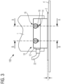
- the reference element 2 in turn serves as a spacer element for setting a distance (ie distance L in the side view of Figure 3 ) between the measuring embodiment 4 and the scanning unit 10.
- the reference element 2 is a flexible film with a predetermined thickness. The predetermined thickness corresponds to the distance L (cf. Figure 3 ).
- first fastening element 16.1 and the first flexible element 18.1 are shown.
- a longitudinal axis S1 of the first fastening element 16.1 is also shown.
- the longitudinal axis S1 runs parallel to the second direction P2.
- the second fastening element 16.2 and the second flexible element 18.2 are shown.
- a longitudinal axis S2 of the second fastening element 16.2 is also shown.
- the longitudinal axis S2 runs parallel to the second direction P2.
- the first flexible element 18.1 and the first fastening element 16.1 form part of a pre-tensioning device.
- a further part of the pre-tensioning device is formed by the second flexible element 18.2 and the second fastening element 16.2.
- the predetermined pressing force F is generated by the flexible elements 18 (ie the first and second flexible elements 18.1, 18.2) (cf. Figure 2 ).
- the pre-tensioning device thus presses the housing 12 of the scanning unit 10 against the reference element 2 in a defined manner.
- the predetermined pressing force F is created essentially in the middle between the cutting line AA and the cutting line BB (cf. Figure 2 and 3 ).
- the flexible elements 18 are designed to press the housing 12 of the scanning unit 10 against the reference element 2 in the first direction P1.
- the flexible elements 18 extend within the through holes 14 in the second direction P2. As in Figure 2 , 4a and 4b the flexible elements 18 (ie the first and second flexible elements 18.1, 18.2) are continuous in the second direction P2.
- FIG. 5a In the sectional view of Figure 5a the first fastening element 16.1 and sections 18.11, 18.12 of a first pair are shown.
- the sections 18.11, 18.12 of the first pair form the first flexible element 18.1 (here an exemplary first alternative embodiment).
- the sectional view of Figure 5a essentially corresponds to the sectional view of Figure 4a .
- Figure 5b the second fastening element 16.2 and sections 18.21, 18.22 of a second pair are shown.
- the sections 18.21, 18.22 of the second pair form the second flexible element 18.2 (here an exemplary first alternative embodiment).
- the sectional view of Figure 5b essentially corresponds to the sectional view of Figure 4b .
- the flexible elements 18 thus comprise the first pair of sections 18.11, 18.12 and the second pair of sections 18.21, 18.22.
- the sections 18.11, 18.12 of the first pair and the sections 18.21, 18.22 of the second pair are each arranged at two ends of the through openings 14 that are opposite one another in the second direction P2.
- the exemplary first alternative design achieves a particularly cost-effective and yet stable structure.
- FIG. 6a In the sectional view of Figure 6a the first fastening element 16.1 and a single section 18.11 are shown.
- the single section 18.11 forms the first flexible element 18.1 (here an exemplary second alternative embodiment).
- the sectional view of Figure 6a essentially corresponds to the sectional view of Figure 4a .
- FIG. 6b In the sectional view of Figure 6b the second fastening element 16.2 and a single section 18.22 are shown.
- the single section 18.22 forms the second flexible element 18.2 (here an exemplary second alternative embodiment).
- the sectional view of Figure 6b essentially corresponds to the sectional view of Figure 4b .
- the flexible elements 18 thus have the single section 18.11 and the single section 18.22, respectively.
- the single section 18.11 and the single section 18.22 are each arranged at an end of the through openings 14 facing away from the object 1.
- the exemplary second alternative design achieves a more cost-effective and yet stable structure compared to the exemplary first alternative design.
- the flexible elements 18 are tubular (cf. Figure 1 ; Figure 2 , 4a and 4b ). Furthermore, the flexible elements 18 can also have one or more tubular sections (cf. Figures 5a and 5b , third embodiment; Figures 6a and 6b , fourth embodiment).
- the flexible elements 18 are in particular elastically deformable elements, for example made of silicone or rubber.
- the flexible elements 18 in the through-openings 14 can be designed differently (e.g. continuous in the first through-opening 14.1 and interrupted in the second through-opening 14.2 and vice versa).
- the flexible elements 18 have a first extension D1 parallel to the first direction P1. Furthermore, the through openings 14 have a second extension D2 parallel to the first direction P1. For example, the first extension D1 is smaller than half of the second extension D2.
- the flexible elements 18 have a first (outer) diameter (e.g. corresponding to the first dimension D1). Furthermore, the fastening elements 16 have a second diameter (ie diameter of the shaft). For example, the first diameter is smaller than the second diameter. As in Figure 1 and 2 As can be seen, the through openings 14 each have a shape/contour adapted to the first and second diameters.
- a single through-opening is provided instead of the multiple through-openings 14.
- a single fastening element can be provided instead of the multiple fastening elements 16.
- a single flexible element can be provided instead of the multiple flexible elements 18.
- the configuration/function of the various elements is analogous to the first to fourth embodiments.
- the various elements are advantageously arranged in the middle of the scanning unit 10 (ie, at a position midway between the section line AA and the section line BB according to Figure 3 ).
- the predetermined pressure force F can be generated essentially in the middle of the scanning unit 10 (analogous to the first to fourth embodiments).
- the invention enables a particularly high-resolution position measurement if the measuring graduation 4.1 is designed to be optically scannable.
- the measuring graduation 4.1 can alternatively also be designed to be magnetically, inductively or capacitively scannable.
Landscapes
- Physics & Mathematics (AREA)
- General Physics & Mathematics (AREA)
- Optics & Photonics (AREA)
- Transmission And Conversion Of Sensor Element Output (AREA)
- Optical Transform (AREA)
Abstract
Description
- Die vorliegende Erfindung betrifft eine Abtasteinheit einer Positionsmesseinrichtung nach dem Oberbegriff des Anspruchs 1.
-
DE 10 2014 213 955 A1 offenbart eine Vorrichtung mit einer Abtasteinheit und einer Montagehilfe, mit der die Abtasteinheit um eine Drehachse eines Referenzelements drehbar ist. Die Montagehilfe ist dazu ausgebildet, um die Abtasteinheit dabei federnd an das Referenzelement zu drängen. - Weitere Vorrichtungen zur Fixierung einer Relativlage zwischen einer Abtasteinheit und einer Maßverkörperung sind aus
WO 02/40947 A1 US 4,639,595 A ,DE 43 04 914 A1 undEP 2 905 582 A1 bekannt. - Der vorliegenden Erfindung liegt die Aufgabe zugrunde, eine Abtasteinheit einer Positionsmesseinrichtung anzugeben, die kompakt und kostengünstig aufgebaut ist und mit der eine einfache Montage mit hoher Genauigkeit ermöglicht wird. Diese Aufgabe wird erfindungsgemäß durch eine Abtasteinheit mit den Merkmalen des Anspruchs 1 gelöst.
- Die erfindungsgemäß ausgebildete Abtasteinheit umfasst ein Gehäuse, ein oder mehrere in dem Gehäuse angeordnete Durchgangsöffnungen zum Befestigen der Abtasteinheit an einem Objekt und ein oder mehrere Befestigungselemente, die sich durch die Durchgangsöffnungen hindurch erstrecken. Die Abtasteinheit weist ein oder mehrere flexible Elemente auf. Die ein oder mehreren flexiblen Elemente erstrecken sich zumindest teilweise durch die Durchgangsöffnungen hindurch. Die ein oder mehreren flexiblen Elemente sind dazu ausgebildet, das Gehäuse der Abtasteinheit an ein Referenzelement anzudrücken.
- Vorzugsweise wird durch die flexiblen Elemente und die Befestigungselemente eine Vorspannvorrichtung gebildet. Die Vorspannvorrichtung kann auch als Montagehilfe bezeichnet werden.
- Es ist vorteilhaft, wenn die flexiblen Elemente dazu ausgebildet sind, eine vorbestimmte Andruckkraft zu erzeugen, durch die das Gehäuse der Abtasteinheit an das Referenzelement angedrückt wird.
- Ferner ist es vorteilhaft, wenn die flexiblen Elemente dazu ausgebildet sind, die Befestigungselemente in den Durchgangsöffnungen derart vorzuspannen, dass die vorbestimmte Andruckkraft erzeugt wird.
- Vorzugsweise sind die flexiblen Elemente schlauchförmig (z. B. hohlzylinderförmig) ausgebildet.
- Vorzugsweise sind die flexiblen Elemente elastisch verformbare Elemente. Beispielsweise sind die flexiblen Elemente aus Silikon oder Gummi hergestellt.
- Vorzugsweise sind die Befestigungselemente als Befestigungsschrauben oder Befestigungsbolzen ausgebildet.
- Eine Positionsmesseinrichtung mit einer Maßverkörperung und der erfindungsgemäßen Abtasteinheit ist im Anspruch 11 angegeben.
- Es ist vorteilhaft, wenn die Positionsmesseinrichtung das Referenzelement aufweist und wenn das Referenzelement zwischen der Maßverkörperung und der Abtasteinheit angeordnet ist.
- Vorzugsweise ist das Referenzelement eine flexible Folie mit einer vorbestimmten Dicke und/oder einer vorbestimmten Krümmung. Beispielsweise entspricht die vorbestimmte Dicke einem Abstand zwischen der Maßverkörperung und der Abtasteinheit. Ferner ist die vorbestimmte Krümmung beispielsweise an einen Radius bzw. Durchmesser der Maßverkörperung angepasst (im Fall einer rotatorischen Positionsmesseinrichtung). Im Fall einer linearen Positionsmesseinrichtung kann die flexible Folie an eine Ebene der Messteilung der Maßverkörperung angepasst sein. In vorteilhafter Weise dient die flexible Folie als Abstandshalteelement.
- Durch die Erfindung wird mit einer kompakt und kostengünstig aufgebauten Abtasteinheit eine einfache Montage einer Positionsmesseinrichtung ermöglicht. Die Positionsmesseinrichtung umfasst eine Maßverkörperung und die Abtasteinheit. Bei der Montage der Positionsmesseinrichtung wird eine hohe Genauigkeit, d. h. eine präzise (bzw. im Wesentlichen fehlerfreie) Einstellung eines Abstands (im Folgenden Abtastspalt) zwischen der Maßverkörperung und der Abtasteinheit, erreicht. Die Montage umfasst beispielsweise die folgenden Schritte: (i) Anordnen eines Referenzelements zwischen der Maßverkörperung und der Abtasteinheit; (ii) ortsfeste Befestigung der Abtasteinheit an einem Objekt derart, dass durch in der Abtasteinheit integrierte flexible Elemente das Gehäuse der Abtasteinheit an das Referenzelement angedrückt wird; und (iii) Entfernen des Referenzelements von der Maßverkörperung und der Abtasteinheit. Die Erfindung ermöglicht insbesondere ein definiertes Andrücken (bzw. eine flexible Anfederung) der Abtasteinheit an das Referenzelement. Dadurch können Fehler oder Ungenauigkeiten bei der Montage, z. B. durch unsachgemäßes manuelles Andrücken der Abtasteinheit, vermieden werden. Somit werden die hohe Genauigkeit der Montage bzw. die fehlerfreie Einstellung des Abtastspalts erreicht.
- Vorteilhafte Ausbildungen der Erfindung entnimmt den abhängigen Ansprüchen.
- Weitere Einzelheiten und Vorteile der vorliegenden Erfindung werden anhand der nachfolgenden Beschreibung von Ausführungsbeispielen der Erfindung in Verbindung mit den Figuren erläutert.
- Es zeigt
- Figur 1
- eine perspektivische Explosionsansicht einer Positionsmesseinrichtung gemäß einem ersten Ausführungsbeispiel mit durchgängig ausgebildeten flexiblen Elementen;
- Figur 2
- eine perspektivische Explosionsansicht einer Positionsmesseinrichtung gemäß einem zweiten Ausführungsbeispiel mit durchgängig ausgebildeten flexiblen Elementen;
- Figur 3
- eine Seitenansicht der Positionsmesseinrichtung nach
Figur 2 mit einer Schnittlinie A-A und einer Schnittlinie B-B; - Figur 4a
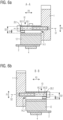
- eine Schnittdarstellung entlang der Schnittlinie A-A in
Figur 3 ; - Figur 4b
- eine Schnittdarstellung entlang der Schnittlinie B-B in
Figur 3 ; - Figur 5a
- eine Schnittdarstellung analog zur Schnittdarstellung nach
Figur 4a mit einem flexiblen Element mit einem ersten Paar von Teilabschnitten; - Figur 5b
- eine Schnittdarstellung analog zur Schnittdarstellung nach
Figur 4b mit einem flexiblen Element mit einem zweiten Paar von Teilabschnitten; - Figur 6a
- eine Schnittdarstellung analog zur Schnittdarstellung nach
Figur 4a mit einem flexiblen Element mit einem einzigen Teilabschnitt; und - Figur 6b
- eine Schnittdarstellung analog zur Schnittdarstellung nach
Figur 4b mit einem flexiblen Element mit einem einzigen Teilabschnitt. - Gleiche Elemente oder funktionell gleiche Elemente sind in den Figuren mit gleichen Bezugszeichen versehen.
- Ein erstes Ausführungsbeispiel wird nachfolgend anhand von
Figur 1 erläutert. Die Positionsmesseinrichtung 100 gemäß dem ersten Ausführungsbeispiel ist insbesondere eine rotatorische Positionsmesseinrichtung. Ein zweites Ausführungsbeispiel wird nachfolgend anhand vonFigur 2 bis 4b erläutert. Die Positionsmesseinrichtung 100 gemäß dem zweiten Ausführungsbeispiel ist insbesondere eine lineare Positionsmesseinrichtung. InFigur 5a und 5b ist eine beispielhafte erste alternative Ausgestaltung von flexiblen Elementen 18 der Positionsmesseinrichtung 100 gemäß dem zweiten Ausführungsbeispiel gezeigt (im Folgenden drittes Ausführungsbeispiel). InFigur 6a und 6b ist eine beispielhafte zweite alternative Ausgestaltung der flexiblen Elemente 18 der Positionsmesseinrichtung 100 gemäß dem zweiten Ausführungsbeispiel gezeigt (im Folgenden viertes Ausführungsbeispiel). - Die Positionsmesseinrichtung 100 nach
Figur 1 umfasst eine Maßverkörperung mit einer Messteilung 4.1 und eine Abtasteinheit 10. Die Abtasteinheit 10 dient zur Abtastung der Messteilung 4.1 der Maßverkörperung. InFigur 1 ist ein Teilungsträger der Maßverkörperung nicht gezeigt. - Ferner umfasst die Positionsmesseinrichtung 100 nach
Figur 1 ein Referenzelement 2. Das Referenzelement 2 ist zwischen der Messteilung 4.1 der Maßverkörperung und der Abtasteinheit 10 angeordnet. Das Referenzelement 2 dient als Abstandshalteelement (z. B. flexible Folie mit einer vorbestimmten Dicke). Das Referenzelement 2 ist im montierten Zustand (d. h. in einem an einem Objekt 1 befestigten Zustand) der Abtasteinheit 10 von der Messteilung 4.1 der Maßverkörperung und der Abtasteinheit 10 entfernbar. - Wie in
Figur 1 gezeigt, umfasst die Abtasteinheit 10 ein Gehäuse 12, mehrere in dem Gehäuse 12 angeordnete Durchgangsöffnungen 14 (erste und zweite Durchgangsöffnung 14.1, 14.2) und mehrere Befestigungselemente 16 (erstes und zweites Befestigungselement 16.1, 16.2). Die Durchgangsöffnungen 14 dienen zum Befestigen der Abtasteinheit 10 an dem Objekt 1. Die Befestigungselemente 16 sind als Befestigungsschrauben oder Befestigungsbolzen ausgebildet und erstrecken sich durch die Durchgangsöffnungen 14 hindurch. Ferner ist inFigur 1 gezeigt, dass die Abtasteinheit 10 mehrere flexible Elemente 18 (erstes und zweites flexibles Element 18.1, 18.2) aufweist. Die flexiblen Elemente 18 erstrecken sich zumindest teilweise durch die Durchgangsöffnungen 14 hindurch. Die flexiblen Elemente 18 sind dazu ausgebildet, das Gehäuse 12 der Abtasteinheit 10 an das Referenzelement 2 anzudrücken. Eine vorbestimmte Andruckkraft ist inFigur 1 durch den Pfeil F dargestellt. - Darüber hinaus ist in
Figur 1 gezeigt, dass die Abtasteinheit 10 mehrere Unterlegscheiben 20 (erste und zweite Unterlegscheibe 20.1, 20.2) aufweist, durch die sich die Befestigungselemente 16 erstrecken. - In
Figur 1 sind eine erste Richtung P1 und eine zweite Richtung P2 gezeigt. Die erste Richtung P1 ist senkrecht zu einer Oberfläche 2.1 des Referenzelements 2. Die zweite Richtung P2 ist senkrecht zu einer Oberfläche 1.1 des Objekts 1. Die vorbestimmte Andruckkraft F ist parallel zur ersten Richtung P1. Die erste Richtung P1 und die zweite Richtung P2 sind zwei zueinander orthogonale Richtungen. - In
Figur 1 ist zudem ein Abschnitt 22 eines Kabels der Abtasteinheit 10 gezeigt. - Die Positionsmesseinrichtung gemäß dem zweiten Ausführungsbeispiel unterscheidet sich von der Positionsmesseinrichtung gemäß dem ersten Ausführungsbeispiel dadurch, dass die Maßverkörperung 4 mit der Messteilung 4.1 ein Maßstab (d. h. Linear-Maßstab) ist. Das Referenzelement 2 ist zwischen der Maßverkörperung 4 in Form des Linear-Maßstabs und der Abtasteinheit 10 angeordnet (vgl.
Figur 2 ). Das Referenzelement 2 dient wiederum als Abstandshalteelement zur Einstellung eines Abstands (d. h. Abstand L in der Seitenansicht vonFigur 3 ) zwischen der Maßverkörperung 4 und der Abtasteinheit 10. Beispielsweise ist das Referenzelement 2 eine flexible Folie mit einer vorbestimmten Dicke. Dabei entspricht die vorbestimmte Dicke dem Abstand L (vgl.Figur 3 ). - In
Figur 2 sind wiederum die vorbestimmte Andruckkraft F sowie die erste Richtung P1 und die zweite Richtung P2 gezeigt. - In der Schnittdarstellung von
Figur 4a sind das erste Befestigungselement 16.1 und das erste flexible Element 18.1 gezeigt. InFigur 4a ist zudem eine Längsachse S1 des ersten Befestigungselements 16.1 gezeigt. Die Längsachse S1 verläuft parallel zur zweiten Richtung P2. In der Schnittdarstellung vonFigur 4b sind das zweite Befestigungselement 16.2 und das zweite flexible Element 18.2 gezeigt. InFigur 4b ist zudem eine Längsachse S2 des zweiten Befestigungselements 16.2 gezeigt. Die Längsachse S2 verläuft parallel zur zweiten Richtung P2. - In Bezug auf
Figur 4a wird durch das erste flexible Element 18.1 und das erste Befestigungselement 16.1 ein Teil einer Vorspannvorrichtung gebildet. In Bezug aufFigur 4b wird durch das zweite flexible Element 18.2 und das zweite Befestigungselement 16.2 ein weiterer Teil der Vorspannvorrichtung gebildet. Insgesamt wird durch die flexiblen Elemente 18 (d. h. das erste und zweite flexible Element 18.1, 18.2) die vorbestimmte Andruckkraft F erzeugt (vgl.Figur 2 ). Durch die Vorspannvorrichtung wird somit das Gehäuse 12 der Abtasteinheit 10 in definierter Weise an das Referenzelement 2 angedrückt. Die vorbestimmte Andruckkraft F entsteht dabei im Wesentlichen in der Mitte zwischen der Schnittlinie A-A und der Schnittlinie B-B (vgl.Figur 2 und3 ). - Wie in
Figur 2 zu erkennen, sind die flexiblen Elemente 18 dazu ausgebildet, das Gehäuse 12 der Abtasteinheit 10 in der ersten Richtung P1 an das Referenzelement 2 anzudrücken. - In Bezug auf
Figur 2 ,4a und 4b erstrecken sich die flexiblen Elemente 18 innerhalb der Durchgangsöffnungen 14 in der zweiten Richtung P2. Wie inFigur 2 ,4a und 4b zu erkennen, sind die flexiblen Elemente 18 (d. h. das erste und zweite flexible Element 18.1, 18.2) in der zweiten Richtung P2 durchgängig ausgebildet. - In der Schnittdarstellung von
Figur 5a sind das erste Befestigungselement 16.1 und Teilabschnitte 18.11, 18.12 eines ersten Paares gezeigt. Die Teilabschnitte 18.11, 18.12 des ersten Paares bilden das erste flexible Element 18.1 (hier beispielhafte erste alternative Ausgestaltung). Die Schnittdarstellung vonFigur 5a entspricht im Wesentlichen der Schnittdarstellung vonFigur 4a . - In
Figur 5b sind das zweite Befestigungselement 16.2 und Teilabschnitte 18.21, 18.22 eines zweiten Paares gezeigt. Die Teilabschnitte 18.21, 18.22 des zweiten Paares bilden das zweite flexible Element 18.2 (hier beispielhafte erste alternative Ausgestaltung). Die Schnittdarstellung vonFigur 5b entspricht im Wesentlichen der Schnittdarstellung vonFigur 4b . - In Bezug auf
Figur 5a und 5b weisen die flexiblen Elemente 18 somit das erste Paar von Teilabschnitten 18.11, 18.12 und das zweite Paar von Teilabschnitten 18.21, 18.22 auf. Wie inFigur 5a und 5b zu erkennen, sind die Teilabschnitte 18.11, 18.12 des ersten Paares und die Teilabschnitte 18.21, 18.22 des zweiten Paares jeweils an zwei in der zweiten Richtung P2 einander gegenüberliegenden Enden der Durchgangsöffnungen 14 angeordnet. Durch die beispielhafte erste alternative Ausgestaltung wird ein besonders kostengünstiger und dennoch stabiler Aufbau erreicht. - In der Schnittdarstellung von
Figur 6a sind das erste Befestigungselement 16.1 und ein einziger Teilabschnitt 18.11 gezeigt. Der einzige Teilabschnitt 18.11 bildet das erste flexible Element 18.1 (hier beispielhafte zweite alternative Ausgestaltung). Die Schnittdarstellung vonFigur 6a entspricht im Wesentlichen der Schnittdarstellung vonFigur 4a . - In der Schnittdarstellung von
Figur 6b sind das zweite Befestigungselement 16.2 und ein einziger Teilabschnitt 18.22 gezeigt. Der einzige Teilabschnitt 18.22 bildet das zweite flexible Element 18.2 (hier beispielhafte zweite alternative Ausgestaltung). Die Schnittdarstellung vonFigur 6b entspricht im Wesentlichen der Schnittdarstellung vonFigur 4b . - In Bezug auf
Figur 6a und 6b weisen die flexiblen Elemente 18 somit den einzigen Teilabschnitt 18.11 bzw. den einzigen Teilabschnitt 18.22 auf. Der einzige Teilabschnitt 18.11 und der einzige Teilabschnitt 18.22 sind jeweils an einem dem Objekt 1 abgewandten Ende der Durchgangsöffnungen 14 angeordnet. Durch die beispielhafte zweite alternative Ausgestaltung wird ein im Vergleich zur beispielhaften ersten alternativen Ausgestaltung kostengünstigerer und dennoch stabiler Aufbau erreicht. - Beim ersten und zweiten Ausführungsbeispiel sind die flexiblen Elemente 18 schlauchförmig ausgebildet (vgl.
Figur 1 ;Figur 2 ,4a und 4b ). Ferner können die flexiblen Elemente 18 auch einen oder mehrere schlauchförmige Teilabschnitte aufweisen (vgl.Figur 5a und 5b , drittes Ausführungsbeispiel;Figur 6a und 6b , viertes Ausführungsbeispiel). Die flexiblen Elemente 18 sind insbesondere elastisch verformbare Elemente, beispielsweise hergestellt aus Silikon oder Gummi. - Alternativ können die flexiblen Elemente 18 in den Durchgangsöffnungen 14 unterschiedlich (z. B. in der ersten Durchgangsöffnung 14.1 durchgängig und in der zweiten Durchgangsöffnung 14.2 unterbrochen und umgekehrt) ausgebildet sein.
- Wie in
Figur 4a, 4b ;Figur 5a, 5b ;Figur 6a, 6b zu erkennen, haben die flexiblen Elemente 18 eine erste Ausdehnung D1 parallel zur ersten Richtung P1. Ferner haben die Durchgangsöffnungen 14 eine zweite Ausdehnung D2 parallel zur ersten Richtung P1. Beispielsweise ist die erste Ausdehnung D1 kleiner als die Hälfte der zweiten Ausdehnung D2. - Bei allen Ausführungsbeispielen haben die flexiblen Elemente 18 einen ersten (äußeren) Durchmesser (z. B. entsprechend der ersten Ausdehnung D1). Ferner haben die Befestigungselemente 16 einen zweiten Durchmesser (d. h. Durchmesser des Schafts). Beispielsweise ist der erste Durchmesser kleiner als der zweite Durchmesser. Wie in
Figur 1 und2 zu erkennen, haben die Durchgangsöffnungen 14 jeweils eine an den ersten und zweiten Durchmesser angepasste Form/Kontur. - Bei einem weiteren (fünften) Ausführungsbeispiel ist anstelle der mehreren Durchgangsöffnungen 14 eine einzige Durchgangsöffnung vorgesehen. Ferner kann anstelle der mehreren Befestigungselemente 16 ein einziges Befestigungselement vorgesehen sein. Darüber hinaus kann anstelle der mehreren flexiblen Elemente 18 ein einziges flexibles Element vorgesehen sein.
- Beim fünften Ausführungsbeispiel ist die Konfiguration/Funktion der verschiedenen Elemente (d. h. einzige Durchgangsöffnung, einziges Befestigungselement und einziges flexibles Element) analog zum ersten bis vierten Ausführungsbeispiel. Ferner sind beim fünften Ausführungsbeispiel die verschiedenen Elemente in vorteilhafter Weise in der Mitte der Abtasteinheit 10 (d. h. an einer Position in der Mitte zwischen der Schnittlinie A-A und der Schnittlinie B-B nach
Figur 3 ) angeordnet. Dadurch kann wiederum die vorbestimmte Andruckkraft F im Wesentlichen in der Mitte der Abtasteinheit 10 erzeugt werden (analog zum ersten bis vierten Ausführungsbeispiel). - Die Erfindung ermöglicht eine besonders hochauflösende Positionsmessung, wenn die Messteilung 4.1 optisch abtastbar ausgebildet ist. Die Messteilung 4.1 kann alternativ auch magnetisch, induktiv oder kapazitiv abtastbar ausgebildet sein.
Claims (15)
- Abtasteinheit (10) einer Positionsmesseinrichtung (100), miteinem Gehäuse (12),einer oder mehreren in dem Gehäuse (12) angeordneten Durchgangsöffnungen (14) zum Befestigen der Abtasteinheit (10) an einem Objekt (1), undeinem oder mehreren Befestigungselementen (16), die sich durch die Durchgangsöffnungen (14) hindurch erstrecken,dadurch gekennzeichnet, dassdie Abtasteinheit (10) ein oder mehrere flexible Elemente (18) aufweist, wobei sich die ein oder mehreren flexiblen Elemente (18) zumindest teilweise durch die Durchgangsöffnungen (14) hindurch erstrecken, wobei die ein oder mehreren flexiblen Elemente (18) dazu ausgebildet sind, das Gehäuse (12) der Abtasteinheit (10) an ein Referenzelement (2) anzudrücken.
- Abtasteinheit (10) nach Anspruch 1, wobei durch die flexiblen Elemente (18) und die Befestigungselemente (16) eine Vorspannvorrichtung gebildet wird.
- Abtasteinheit (10) nach Anspruch 1 oder 2, wobei die flexiblen Elemente (18) dazu ausgebildet sind, eine vorbestimmte Andruckkraft (F) zu erzeugen, durch die das Gehäuse (12) der Abtasteinheit (10) an das Referenzelement (2) angedrückt wird.
- Abtasteinheit (10) nach einem der vorhergehenden Ansprüche, wobei die flexiblen Elemente (18) dazu ausgebildet sind, das Gehäuse (12) der Abtasteinheit (10) in einer ersten Richtung (P1) senkrecht zu einer Oberfläche (2.1) des Referenzelements (2) an das Referenzelement (2) anzudrücken.
- Abtasteinheit (10) nach einem der vorhergehenden Ansprüche, wobei sich die flexiblen Elemente (18) innerhalb der Durchgangsöffnungen (14) in einer zweiten Richtung (P2) senkrecht zu einer Oberfläche (1.1) des Objekts (1) erstrecken, wobei die flexiblen Elemente (18) in der zweiten Richtung (P2) durchgängig ausgebildet sind.
- Abtasteinheit (10) nach einem der Ansprüche 1 bis 4, wobei die flexiblen Elemente (18) ein erstes Paar von Teilabschnitten (18.11, 18.12) und ein zweites Paar von Teilabschnitten (18.21, 18.22) aufweisen, wobei die Teilabschnitte (18.11, 18.12) des ersten Paares und die Teilabschnitte (18.21, 18.22) des zweiten Paares jeweils an zwei in einer zweiten Richtung (P2) senkrecht zu einer Oberfläche (1.1) des Objekts (1) einander gegenüberliegenden Enden der Durchgangsöffnungen (14) angeordnet sind.
- Abtasteinheit (10) nach einem der vorhergehenden Ansprüche, wobei die flexiblen Elemente (18) schlauchförmig ausgebildet sind.
- Abtasteinheit (10) nach einem der vorhergehenden Ansprüche, wobei die flexiblen Elemente (18) elastisch verformbare Elemente sind.
- Abtasteinheit (10) nach einem der vorhergehenden Ansprüche, wobei die flexiblen Elemente (18) aus Silikon oder Gummi hergestellt sind.
- Abtasteinheit (10) nach einem der vorhergehenden Ansprüche, wobei die Befestigungselemente (16) als Befestigungsschrauben oder Befestigungsbolzen ausgebildet sind.
- Positionsmesseinrichtung (100) mit einer Maßverkörperung (4) und einer Abtasteinheit (10) nach einem der vorhergehenden Ansprüche.
- Positionsmesseinrichtung (100) nach Anspruch 11, wobei die Positionsmesseinrichtung (100) das Referenzelement (2) aufweist, wobei das Referenzelement (2) zwischen der Maßverkörperung (4) und der Abtasteinheit (10) angeordnet ist.
- Positionsmesseinrichtung (100) nach Anspruch 12, wobei das Referenzelement (2) ein Abstandshalteelement zur Einstellung eines Abstands (L) zwischen der Maßverkörperung (4) und der Abtasteinheit (10) ist.
- Positionsmesseinrichtung (100) nach Anspruch 12 oder 13, wobei das Referenzelement (2) eine flexible Folie mit einer vorbestimmten Dicke ist.
- Positionsmesseinrichtung (100) nach einem der Ansprüche 12 bis 14, wobei das Referenzelement (2) im montierten Zustand der Abtasteinheit (10) von der Maßverkörperung (4) und der Abtasteinheit (10) entfernbar ist.
Priority Applications (6)
| Application Number | Priority Date | Filing Date | Title |
|---|---|---|---|
| ES23180649T ES3061089T3 (en) | 2023-06-21 | 2023-06-21 | Scanning unit of a position measuring device |
| EP23180649.8A EP4481331B1 (de) | 2023-06-21 | 2023-06-21 | Abtasteinheit einer positionsmesseinrichtung |
| DE102024000980.9A DE102024000980A1 (de) | 2023-06-21 | 2024-03-25 | Abtasteinheit einer Positionsmesseinrichtung |
| JP2024065144A JP2025003312A (ja) | 2023-06-21 | 2024-04-15 | 位置測定装置の走査ユニット |
| US18/744,746 US20240427137A1 (en) | 2023-06-21 | 2024-06-17 | Scanning unit of a position-measuring device |
| CN202410809138.XA CN119178364A (zh) | 2023-06-21 | 2024-06-21 | 位置测量装置的扫描单元 |
Applications Claiming Priority (1)
| Application Number | Priority Date | Filing Date | Title |
|---|---|---|---|
| EP23180649.8A EP4481331B1 (de) | 2023-06-21 | 2023-06-21 | Abtasteinheit einer positionsmesseinrichtung |
Publications (2)
| Publication Number | Publication Date |
|---|---|
| EP4481331A1 true EP4481331A1 (de) | 2024-12-25 |
| EP4481331B1 EP4481331B1 (de) | 2025-12-10 |
Family
ID=86942665
Family Applications (1)
| Application Number | Title | Priority Date | Filing Date |
|---|---|---|---|
| EP23180649.8A Active EP4481331B1 (de) | 2023-06-21 | 2023-06-21 | Abtasteinheit einer positionsmesseinrichtung |
Country Status (6)
| Country | Link |
|---|---|
| US (1) | US20240427137A1 (de) |
| EP (1) | EP4481331B1 (de) |
| JP (1) | JP2025003312A (de) |
| CN (1) | CN119178364A (de) |
| DE (1) | DE102024000980A1 (de) |
| ES (1) | ES3061089T3 (de) |
Citations (7)
| Publication number | Priority date | Publication date | Assignee | Title |
|---|---|---|---|---|
| US4639595A (en) | 1983-02-21 | 1987-01-27 | Alps Electric Co., Ltd. | Optical rotary encoder |
| DE4304914A1 (de) | 1992-02-28 | 1993-09-02 | Heidenhain Gmbh Dr Johannes | |
| WO2000008418A1 (de) * | 1998-08-08 | 2000-02-17 | Dr. Johannes Heidenhain Gmbh | Verfahren zur montage einer positionsmesseinrichtung und positioniermittel zur montage |
| WO2002040947A1 (de) | 2000-11-17 | 2002-05-23 | Optolab Licensing Gmbh | Positionsmesssystem und montageverfahren dafür |
| EP2905582A1 (de) | 2014-02-11 | 2015-08-12 | Dr. Johannes Heidenhain GmbH | Vormontierte Winkelmesseinrichtung |
| DE102014213955A1 (de) | 2014-07-17 | 2016-01-21 | Dr. Johannes Heidenhain Gmbh | Vorrichtung mit einer Abtasteinheit und einer Montagehilfe und Verfahren zur Montage der Abtasteinheit |
| DE102022000396A1 (de) * | 2021-02-08 | 2022-08-11 | Mitutoyo Corporation | Verlagerungsmessapparat |
-
2023
- 2023-06-21 ES ES23180649T patent/ES3061089T3/es active Active
- 2023-06-21 EP EP23180649.8A patent/EP4481331B1/de active Active
-
2024
- 2024-03-25 DE DE102024000980.9A patent/DE102024000980A1/de active Pending
- 2024-04-15 JP JP2024065144A patent/JP2025003312A/ja active Pending
- 2024-06-17 US US18/744,746 patent/US20240427137A1/en active Pending
- 2024-06-21 CN CN202410809138.XA patent/CN119178364A/zh active Pending
Patent Citations (7)
| Publication number | Priority date | Publication date | Assignee | Title |
|---|---|---|---|---|
| US4639595A (en) | 1983-02-21 | 1987-01-27 | Alps Electric Co., Ltd. | Optical rotary encoder |
| DE4304914A1 (de) | 1992-02-28 | 1993-09-02 | Heidenhain Gmbh Dr Johannes | |
| WO2000008418A1 (de) * | 1998-08-08 | 2000-02-17 | Dr. Johannes Heidenhain Gmbh | Verfahren zur montage einer positionsmesseinrichtung und positioniermittel zur montage |
| WO2002040947A1 (de) | 2000-11-17 | 2002-05-23 | Optolab Licensing Gmbh | Positionsmesssystem und montageverfahren dafür |
| EP2905582A1 (de) | 2014-02-11 | 2015-08-12 | Dr. Johannes Heidenhain GmbH | Vormontierte Winkelmesseinrichtung |
| DE102014213955A1 (de) | 2014-07-17 | 2016-01-21 | Dr. Johannes Heidenhain Gmbh | Vorrichtung mit einer Abtasteinheit und einer Montagehilfe und Verfahren zur Montage der Abtasteinheit |
| DE102022000396A1 (de) * | 2021-02-08 | 2022-08-11 | Mitutoyo Corporation | Verlagerungsmessapparat |
Also Published As
| Publication number | Publication date |
|---|---|
| JP2025003312A (ja) | 2025-01-09 |
| CN119178364A (zh) | 2024-12-24 |
| DE102024000980A1 (de) | 2024-12-24 |
| EP4481331B1 (de) | 2025-12-10 |
| US20240427137A1 (en) | 2024-12-26 |
| ES3061089T3 (en) | 2026-03-31 |
Similar Documents
| Publication | Publication Date | Title |
|---|---|---|
| EP2496851B1 (de) | Radial einstellbare wellenlageranordnung | |
| WO2011012399A1 (de) | Drehzahlsensor | |
| WO2010022841A1 (de) | Befestigungsanordnung mit toleranzausgleich | |
| EP1434952A1 (de) | Verfahren zur herstellung einer rohrfeder sowie aktoreinheit mit einer solchen rohrfeder | |
| EP4481331B1 (de) | Abtasteinheit einer positionsmesseinrichtung | |
| CH676025A5 (de) | ||
| WO2015032488A1 (de) | Optische baugruppe mit einer monolithischen fassung mit in einer gleichen richtung wirkenden stellschrauben | |
| DE19735753A1 (de) | Drehstabanordnung | |
| DE102005009925A1 (de) | Verfahren zur massgerechten Arretierung zweier Bauteile aneinander | |
| DE102019208165B3 (de) | Blattfederaufnahme zur Aufnahme einer Blattfeder eines Kraftfahrzeuges, Blattfedereinspannung und Kraftfahrzeug | |
| DE19928302B4 (de) | Vorrichtung zum Befestigen von Seilzugelementen | |
| DE3610283A1 (de) | Gelenkverbindung | |
| EP4502400B1 (de) | Vorrichtung zur einstellung der vorspannkraft einer feder | |
| DE102024130492B4 (de) | Gelenkgabel für eine Hinterachslenkung | |
| DE102020109363B4 (de) | Lagerbuchse mit Rippenelement | |
| EP1081463B1 (de) | Wegmesssystem | |
| DE4312843A1 (de) | Zugkraftmeßeinrichtung | |
| EP2274540B1 (de) | Schaltvorrichtung mit einer anordnung zum ausgleich von lageabweichungen | |
| WO1999013340A1 (de) | Vorrichtung zum befestigen eines winkelgebers | |
| EP1669618A2 (de) | Spindelmutter-Lageranordnung | |
| DE102022130122A1 (de) | Adapter zur Befestigung eines Rotors eines Sensors an einem Ende einer Welle | |
| DE102015108710B4 (de) | Spannelement für eine Spannvorrichtung, sowie Spannvorrichtung | |
| DE102022101282A1 (de) | Gleitlagereinheit zur Lagerung einer Betätigungsstange | |
| AT503331B1 (de) | Getriebe | |
| DE102023118361A1 (de) | Fixiereinheit und Stellschraubenanordnung |
Legal Events
| Date | Code | Title | Description |
|---|---|---|---|
| PUAI | Public reference made under article 153(3) epc to a published international application that has entered the european phase |
Free format text: ORIGINAL CODE: 0009012 |
|
| STAA | Information on the status of an ep patent application or granted ep patent |
Free format text: STATUS: THE APPLICATION HAS BEEN PUBLISHED |
|
| AK | Designated contracting states |
Kind code of ref document: A1 Designated state(s): AL AT BE BG CH CY CZ DE DK EE ES FI FR GB GR HR HU IE IS IT LI LT LU LV MC ME MK MT NL NO PL PT RO RS SE SI SK SM TR |
|
| STAA | Information on the status of an ep patent application or granted ep patent |
Free format text: STATUS: REQUEST FOR EXAMINATION WAS MADE |
|
| GRAP | Despatch of communication of intention to grant a patent |
Free format text: ORIGINAL CODE: EPIDOSNIGR1 |
|
| STAA | Information on the status of an ep patent application or granted ep patent |
Free format text: STATUS: GRANT OF PATENT IS INTENDED |
|
| 17P | Request for examination filed |
Effective date: 20250625 |
|
| INTG | Intention to grant announced |
Effective date: 20250708 |
|
| RIC1 | Information provided on ipc code assigned before grant |
Ipc: G01D 5/244 20060101AFI20250627BHEP |
|
| GRAS | Grant fee paid |
Free format text: ORIGINAL CODE: EPIDOSNIGR3 |
|
| GRAA | (expected) grant |
Free format text: ORIGINAL CODE: 0009210 |
|
| STAA | Information on the status of an ep patent application or granted ep patent |
Free format text: STATUS: THE PATENT HAS BEEN GRANTED |
|
| AK | Designated contracting states |
Kind code of ref document: B1 Designated state(s): AL AT BE BG CH CY CZ DE DK EE ES FI FR GB GR HR HU IE IS IT LI LT LU LV MC ME MK MT NL NO PL PT RO RS SE SI SK SM TR |
|
| REG | Reference to a national code |
Ref country code: CH Ref legal event code: F10 Free format text: ST27 STATUS EVENT CODE: U-0-0-F10-F00 (AS PROVIDED BY THE NATIONAL OFFICE) Effective date: 20251210 Ref country code: GB Ref legal event code: FG4D Free format text: NOT ENGLISH |
|
| REG | Reference to a national code |
Ref country code: DE Ref legal event code: R096 Ref document number: 502023002413 Country of ref document: DE |
|
| REG | Reference to a national code |
Ref country code: IE Ref legal event code: FG4D Free format text: LANGUAGE OF EP DOCUMENT: GERMAN |
|
| REG | Reference to a national code |
Ref country code: CH Ref legal event code: R14 Free format text: ST27 STATUS EVENT CODE: U-0-0-R10-R14 (AS PROVIDED BY THE NATIONAL OFFICE) Effective date: 20260206 |
|
| RAP2 | Party data changed (patent owner data changed or rights of a patent transferred) |
Owner name: RSF ELEKTRONIK GES.M.B.H. |
|
| REG | Reference to a national code |
Ref country code: DE Ref legal event code: R081 Ref document number: 502023002413 Country of ref document: DE Owner name: RSF ELEKTRONIK GES.M.B.H., AT Free format text: FORMER OWNER: AMO AUTOMATISIERUNG MESSTECHNIK OPTIK GMBH, ST.PETER AM HART, AT |
|
| REG | Reference to a national code |
Ref country code: ES Ref legal event code: FG2A Ref document number: 3061089 Country of ref document: ES Kind code of ref document: T3 Effective date: 20260331 |
|
| REG | Reference to a national code |
Ref country code: LT Ref legal event code: MG9D |
|
| PG25 | Lapsed in a contracting state [announced via postgrant information from national office to epo] |
Ref country code: NO Free format text: LAPSE BECAUSE OF FAILURE TO SUBMIT A TRANSLATION OF THE DESCRIPTION OR TO PAY THE FEE WITHIN THE PRESCRIBED TIME-LIMIT Effective date: 20260310 |
|
| PG25 | Lapsed in a contracting state [announced via postgrant information from national office to epo] |
Ref country code: FI Free format text: LAPSE BECAUSE OF FAILURE TO SUBMIT A TRANSLATION OF THE DESCRIPTION OR TO PAY THE FEE WITHIN THE PRESCRIBED TIME-LIMIT Effective date: 20251210 Ref country code: HR Free format text: LAPSE BECAUSE OF FAILURE TO SUBMIT A TRANSLATION OF THE DESCRIPTION OR TO PAY THE FEE WITHIN THE PRESCRIBED TIME-LIMIT Effective date: 20251210 |
|
| REG | Reference to a national code |
Ref country code: NL Ref legal event code: MP Effective date: 20251210 |
|
| PG25 | Lapsed in a contracting state [announced via postgrant information from national office to epo] |
Ref country code: RS Free format text: LAPSE BECAUSE OF FAILURE TO SUBMIT A TRANSLATION OF THE DESCRIPTION OR TO PAY THE FEE WITHIN THE PRESCRIBED TIME-LIMIT Effective date: 20260310 |
|
| PG25 | Lapsed in a contracting state [announced via postgrant information from national office to epo] |
Ref country code: LV Free format text: LAPSE BECAUSE OF FAILURE TO SUBMIT A TRANSLATION OF THE DESCRIPTION OR TO PAY THE FEE WITHIN THE PRESCRIBED TIME-LIMIT Effective date: 20251210 |
|
| PG25 | Lapsed in a contracting state [announced via postgrant information from national office to epo] |
Ref country code: BG Free format text: LAPSE BECAUSE OF FAILURE TO SUBMIT A TRANSLATION OF THE DESCRIPTION OR TO PAY THE FEE WITHIN THE PRESCRIBED TIME-LIMIT Effective date: 20251210 |