EP4481299A1 - Cryocooler compressor - Google Patents
Cryocooler compressor Download PDFInfo
- Publication number
- EP4481299A1 EP4481299A1 EP24179567.3A EP24179567A EP4481299A1 EP 4481299 A1 EP4481299 A1 EP 4481299A1 EP 24179567 A EP24179567 A EP 24179567A EP 4481299 A1 EP4481299 A1 EP 4481299A1
- Authority
- EP
- European Patent Office
- Prior art keywords
- compressor
- refrigerant gas
- heat exchanger
- double pipe
- cryocooler
- Prior art date
- Legal status (The legal status is an assumption and is not a legal conclusion. Google has not performed a legal analysis and makes no representation as to the accuracy of the status listed.)
- Pending
Links
Images


Classifications
-
- F—MECHANICAL ENGINEERING; LIGHTING; HEATING; WEAPONS; BLASTING
- F25—REFRIGERATION OR COOLING; COMBINED HEATING AND REFRIGERATION SYSTEMS; HEAT PUMP SYSTEMS; MANUFACTURE OR STORAGE OF ICE; LIQUEFACTION SOLIDIFICATION OF GASES
- F25B—REFRIGERATION MACHINES, PLANTS OR SYSTEMS; COMBINED HEATING AND REFRIGERATION SYSTEMS; HEAT PUMP SYSTEMS
- F25B9/00—Compression machines, plants or systems, in which the refrigerant is air or other gas of low boiling point
- F25B9/002—Compression machines, plants or systems, in which the refrigerant is air or other gas of low boiling point characterised by the refrigerant
-
- F—MECHANICAL ENGINEERING; LIGHTING; HEATING; WEAPONS; BLASTING
- F25—REFRIGERATION OR COOLING; COMBINED HEATING AND REFRIGERATION SYSTEMS; HEAT PUMP SYSTEMS; MANUFACTURE OR STORAGE OF ICE; LIQUEFACTION SOLIDIFICATION OF GASES
- F25B—REFRIGERATION MACHINES, PLANTS OR SYSTEMS; COMBINED HEATING AND REFRIGERATION SYSTEMS; HEAT PUMP SYSTEMS
- F25B31/00—Compressor arrangements
- F25B31/006—Cooling of compressor or motor
-
- F—MECHANICAL ENGINEERING; LIGHTING; HEATING; WEAPONS; BLASTING
- F04—POSITIVE - DISPLACEMENT MACHINES FOR LIQUIDS; PUMPS FOR LIQUIDS OR ELASTIC FLUIDS
- F04B—POSITIVE-DISPLACEMENT MACHINES FOR LIQUIDS; PUMPS
- F04B39/00—Component parts, details, or accessories, of pumps or pumping systems specially adapted for elastic fluids, not otherwise provided for in, or of interest apart from, groups F04B25/00 - F04B37/00
- F04B39/06—Cooling; Heating; Prevention of freezing
-
- F—MECHANICAL ENGINEERING; LIGHTING; HEATING; WEAPONS; BLASTING
- F25—REFRIGERATION OR COOLING; COMBINED HEATING AND REFRIGERATION SYSTEMS; HEAT PUMP SYSTEMS; MANUFACTURE OR STORAGE OF ICE; LIQUEFACTION SOLIDIFICATION OF GASES
- F25B—REFRIGERATION MACHINES, PLANTS OR SYSTEMS; COMBINED HEATING AND REFRIGERATION SYSTEMS; HEAT PUMP SYSTEMS
- F25B9/00—Compression machines, plants or systems, in which the refrigerant is air or other gas of low boiling point
- F25B9/14—Compression machines, plants or systems, in which the refrigerant is air or other gas of low boiling point characterised by the cycle used, e.g. Stirling cycle
-
- F—MECHANICAL ENGINEERING; LIGHTING; HEATING; WEAPONS; BLASTING
- F28—HEAT EXCHANGE IN GENERAL
- F28D—HEAT-EXCHANGE APPARATUS, NOT PROVIDED FOR IN ANOTHER SUBCLASS, IN WHICH THE HEAT-EXCHANGE MEDIA DO NOT COME INTO DIRECT CONTACT
- F28D7/00—Heat-exchange apparatus having stationary tubular conduit assemblies for both heat-exchange media, the media being in contact with different sides of a conduit wall
- F28D7/10—Heat-exchange apparatus having stationary tubular conduit assemblies for both heat-exchange media, the media being in contact with different sides of a conduit wall the conduits being arranged one within the other, e.g. concentrically
- F28D7/106—Heat-exchange apparatus having stationary tubular conduit assemblies for both heat-exchange media, the media being in contact with different sides of a conduit wall the conduits being arranged one within the other, e.g. concentrically consisting of two coaxial conduits or modules of two coaxial conduits
-
- F—MECHANICAL ENGINEERING; LIGHTING; HEATING; WEAPONS; BLASTING
- F25—REFRIGERATION OR COOLING; COMBINED HEATING AND REFRIGERATION SYSTEMS; HEAT PUMP SYSTEMS; MANUFACTURE OR STORAGE OF ICE; LIQUEFACTION SOLIDIFICATION OF GASES
- F25B—REFRIGERATION MACHINES, PLANTS OR SYSTEMS; COMBINED HEATING AND REFRIGERATION SYSTEMS; HEAT PUMP SYSTEMS
- F25B2339/00—Details of evaporators; Details of condensers
- F25B2339/04—Details of condensers
- F25B2339/047—Water-cooled condensers
-
- F—MECHANICAL ENGINEERING; LIGHTING; HEATING; WEAPONS; BLASTING
- F25—REFRIGERATION OR COOLING; COMBINED HEATING AND REFRIGERATION SYSTEMS; HEAT PUMP SYSTEMS; MANUFACTURE OR STORAGE OF ICE; LIQUEFACTION SOLIDIFICATION OF GASES
- F25B—REFRIGERATION MACHINES, PLANTS OR SYSTEMS; COMBINED HEATING AND REFRIGERATION SYSTEMS; HEAT PUMP SYSTEMS
- F25B31/00—Compressor arrangements
- F25B31/002—Lubrication
- F25B31/004—Lubrication oil recirculating arrangements
-
- F—MECHANICAL ENGINEERING; LIGHTING; HEATING; WEAPONS; BLASTING
- F28—HEAT EXCHANGE IN GENERAL
- F28D—HEAT-EXCHANGE APPARATUS, NOT PROVIDED FOR IN ANOTHER SUBCLASS, IN WHICH THE HEAT-EXCHANGE MEDIA DO NOT COME INTO DIRECT CONTACT
- F28D21/00—Heat-exchange apparatus not covered by any of the groups F28D1/00 - F28D20/00
- F28D2021/0019—Other heat exchangers for particular applications; Heat exchange systems not otherwise provided for
- F28D2021/0033—Other heat exchangers for particular applications; Heat exchange systems not otherwise provided for for cryogenic applications
-
- F—MECHANICAL ENGINEERING; LIGHTING; HEATING; WEAPONS; BLASTING
- F28—HEAT EXCHANGE IN GENERAL
- F28D—HEAT-EXCHANGE APPARATUS, NOT PROVIDED FOR IN ANOTHER SUBCLASS, IN WHICH THE HEAT-EXCHANGE MEDIA DO NOT COME INTO DIRECT CONTACT
- F28D21/00—Heat-exchange apparatus not covered by any of the groups F28D1/00 - F28D20/00
- F28D2021/0019—Other heat exchangers for particular applications; Heat exchange systems not otherwise provided for
- F28D2021/0068—Other heat exchangers for particular applications; Heat exchange systems not otherwise provided for for refrigerant cycles
Definitions
- the present invention relates to a cryocooler compressor.
- a cryocooler such as a Gifford-McMahon (GM) cryocooler includes a compressor of a refrigerant gas to supply a high-pressure refrigerant gas to a cold head.
- the compressor includes components such as a compressor main body, an oil separator, an adsorber, a storage tank, and a control device (for example, Japanese Unexamined Patent Publication No. 2001-74326 ).
- the compressor for the cryocooler is usually provided with a heat exchanger the cools the compressor.
- a heat exchanger the cools the compressor.
- An exemplary object of one embodiment of the present invention is to propose heat exchanger disposition that enables reduction in footprint of the heat exchanger in the cryocooler compressor.
- a cryocooler compressor including a compressor casing and a double pipe-type heat exchanger that is accommodated in the compressor casing and cools the compressor.
- the double pipe-type heat exchanger includes a double pipe disposed along at least one surface of the compressor casing.
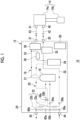
- Fig. 1 is a diagram schematically showing a cryocooler 10 according to the embodiment.
- the cryocooler 10 is used to provide cryogenic cooling to an object or a medium.
- the cryocooler 10 may be used as a cooling source for a superconducting magnet device.
- the superconducting magnet device is mounted on, for example, a high magnetic field using device as a magnetic field source of an accelerator such as a single crystal pulling device, a nuclear magnetic resonance (NMR) system, a magnetic resonance imaging (MRI) system, and a cyclotron, a high energy physical system such as a nuclear fusion system, or other high magnetic field using devices (not shown) and can generate a high magnetic field required for the devices.
- a high magnetic field using device such as a magnetic field source of an accelerator such as a single crystal pulling device, a nuclear magnetic resonance (NMR) system, a magnetic resonance imaging (MRI) system, and a cyclotron
- NMR nuclear magnetic resonance
- MRI magnetic resonance imaging
- the cryocooler 10 includes a compressor 12 and a cold head 14.
- the compressor 12 is configured to collect a refrigerant gas of the cryocooler 10 from the cold head 14, to pressurize the collected refrigerant gas, and to supply the refrigerant gas to the cold head 14 again.
- the compressor 12 is also referred to as a compressor unit.
- the cold head 14 is also referred to as an expander and includes a room temperature section 14a and a low-temperature section 14b which is also referred to as a cooling stage.
- the refrigerant gas is also referred to as a working gas, and other suitable gases may be used although a helium gas is typically used.
- the compressor 12 and the cold head 14 constitute a refrigeration cycle of the cryocooler 10, whereby the low-temperature section 14b is cooled to a desired cryogenic temperature.
- the low-temperature section 14b can cool an object to be cooled such as a superconducting magnet.
- cryocooler 10 is, for example, a single-stage or two-stage Gifford-McMahon (GM) cryocooler
- the cryocooler 10 may be a pulse tube cryocooler, a Stirling cryocooler, or other types of cryocoolers.
- the cold head 14 has a different configuration depending on the type of the cryocooler 10, the compressor 12 can use a configuration described below regardless of the type of the cryocooler 10.
- both a pressure of a refrigerant gas supplied from the compressor 12 to the cold head 14 and a pressure of a refrigerant gas collected from the cold head 14 to the compressor 12 are considerably higher than the atmospheric pressure, and can be called a first high pressure and a second high pressure, respectively.
- the first high pressure and the second high pressure are also simply called a high pressure and a low pressure, respectively.
- the high pressure is, for example, 2 to 3 MPa.
- the low pressure is, for example, 0.5 to 1.5 MPa and is, for example, about 0.8 MPa.
- the compressor 12 is an oil-lubricated cryocooler compressor, and includes a compressor main body 16, a refrigerant gas line 18, and an oil circulation line 20.
- the refrigerant gas line 18 is shown by a solid line
- the oil circulation line 20 is shown by a broken line.
- the compressor 12 includes a compressor casing 24 that accommodates each component of the compressor 12, such as the compressor main body 16, the refrigerant gas line 18, and the oil circulation line 20.
- the compressor main body 16 is configured to internally compress a refrigerant gas sucked from a suction port of the compressor main body 16 and to discharge the refrigerant gas from a discharge port.
- An oil is used in the compressor main body 16 for the sake of cooling and lubrication, and the sucked refrigerant gas is directly exposed to the oil in the compressor main body 16. Accordingly, the refrigerant gas is delivered from the discharge port in a state where the oil is slightly mixed.
- the compressor main body 16 may be, for example, a scroll type pump, a rotary type pump, or other pumps that pressurize a refrigerant gas.
- the compressor main body 16 may be configured to discharge the refrigerant gas at a fixed and constant flow rate. Alternatively, the compressor main body 16 may be configured to vary the flow rate of the refrigerant gas to be discharged.
- the compressor main body 16 may be called a compression capsule.
- the refrigerant gas line 18 includes a discharge port 30, a suction port 31, a discharge flow path 32, and a suction flow path 33.
- the discharge port 30 is an outlet of a refrigerant gas that is installed in the compressor casing 24 in order to deliver the refrigerant gas, which is pressurized to a high pressure by the compressor main body 16, from the compressor 12, and the suction port 31 is an inlet of the refrigerant gas that is installed in the compressor casing 24 in order for the compressor 12 to receive a low-pressure refrigerant gas.
- the compressor casing 24 accommodates the discharge flow path 32 and the suction flow path 33.
- the discharge port of the compressor main body 16 is connected to the discharge port 30 by the discharge flow path 32, and the suction port 31 is connected to the suction port of the compressor main body 16 by the suction flow path 33.
- the refrigerant gas line 18 is connected to the cold head 14.
- a high-pressure port 40 and a low-pressure port 41 are provided in the room temperature section 14a of the cold head 14.
- the high-pressure port 40 is connected to the discharge port 30 by a high-pressure pipe 42, and the low-pressure port 41 is connected to the suction port 31 by a low-pressure pipe 43.
- the oil separator 34 and the adsorber 35 are provided in the discharge flow path 32.
- the oil separator 34 is provided in order to separate an oil, which is mixed in a refrigerant gas as passing through the compressor main body 16, out from the refrigerant gas.
- the adsorber 35 is provided in order to remove, for example, a vaporized oil and other contaminants remaining in the refrigerant gas from the refrigerant gas through adsorption.
- the oil separator 34 and the adsorber 35 are connected in series. In the discharge flow path 32, the oil separator 34 is disposed on the compressor main body 16 side, and the adsorber 35 is disposed on the discharge port 30 side.
- An oil return line 21 that connects the oil separator 34 to the compressor main body 16 is provided.
- An oil collected by the oil separator 34 can be returned to the compressor main body 16 through the oil return line 21.
- a filter that removes dust included in the oil separated out by the oil separator 34 and an orifice that controls the amount of the oil returning to the compressor main body 16 may be provided.
- a storage tank 36 is provided at the suction flow path 33.
- the storage tank 36 is provided as a volume for removing pulsation included in a low-pressure refrigerant gas returning from the cold head 14 to the compressor 12.
- a bypass valve 38 that connects the discharge flow path 32 to the suction flow path 33 to bypass the compressor main body 16 is provided at the refrigerant gas line 18.
- the bypass valve 38 branches off from the discharge flow path 32 between the oil separator 34 and the adsorber 35 and is connected to the suction flow path 33 between the compressor main body 16 and the storage tank 36.
- the bypass valve 38 is provided in order to control a flow rate of a refrigerant gas and/or in order to equalize the discharge flow path 32 and the suction flow path 33 when the compressor 12 is stopped.
- the oil circulation line 20 connects an oil outlet to an oil inlet of the compressor main body 16 in order to return the oil flowing out from the compressor main body 16 to the compressor main body 16 again.
- the oil circulation line 20 may be provided with an orifice that controls a flow rate of an oil flowing therein.
- a filter that removes dust included in the oil may be provided at the oil circulation line 20.
- the compressor 12 further includes a heat exchanger 22 that is accommodated in the compressor casing 24 and cools the compressor 12.
- the heat exchanger 22 includes a refrigerant gas cooler 22a that cools the refrigerant gas line 18 through heat exchange between the refrigerant gas and a cooling medium, and an oil cooler 22b that cools the oil circulation line 20 through heat exchange between the oil and the cooling medium.
- the refrigerant gas cooler 22a is disposed between the compressor main body 16 and the oil separator 34 in the discharge flow path 32, and cools a high-pressure refrigerant gas heated by compression heat generated with the compression of the refrigerant gas in the compressor main body 16.
- the refrigerant gas cooler 22a cools the refrigerant gas through heat exchange between the refrigerant gas and the cooling medium.
- the cooled refrigerant gas is purified by the oil separator 34 and the adsorber 35.
- the oil cooler 22b cools the oil through heat exchange between the oil flowing out from the oil outlet of the compressor main body 16 to the oil circulation line 20 and the cooling medium.
- the cooled oil is returned into the compressor main body 16 from the oil inlet of the compressor main body 16.
- the cooling medium is supplied from the outside to the compressor 12 through a cooling medium intake 44, and is discharged to the outside of the compressor 12 from a cooling medium discharge port 45 via the refrigerant gas cooler 22a and the oil cooler 22b.
- the cooling medium may be a coolant, for example, water. In this manner, compression heat generated by the compressor main body 16 is removed to the outside of the compressor 12 together with the cooling medium.
- the cooling medium may be cooled by, for example, a chiller (not shown) and may be supplied again.
- the heat exchanger 22 is a double pipe-type heat exchanger. Therefore, the heat exchanger 22 includes an outer tube and an inner tube inserted into the outer tube.
- the cooling medium is supplied to one of the outer tube and the inner tube, a fluid to be cooled is supplied to the other. Accordingly, heat exchange between the cooling medium and the target fluid is performed, and the fluid can be cooled.
- the refrigerant gas cooler 22a cooling water may be supplied to the outer tube, and the refrigerant gas may be supplied to the inner tube.
- the oil cooler 22b cooling water may be supplied to the outer tube, and oil may be supplied to the inner tube.
- the compressor casing 24 may accommodate a control device 50 for controlling the cryocooler 10.
- the control device 50 may include a control circuit configured to receive an output from various sensors provided in the cryocooler 10 and to control various devices of the cryocooler 10 based on the sensor output.
- the sensor may include, for example, a refrigerant gas temperature sensor and a refrigerant gas pressure sensor provided in the refrigerant gas line 18, an oil temperature sensor provided in the oil circulation line 20, or a cooling temperature sensor provided in the low-temperature section 14b of the cold head 14.
- the device controlled based on the sensor output may include, for example, a compressor motor that drives the compressor main body 16, the bypass valve 38, and a cold head motor that drives the cold head 14.
- the control device 50 may include a compressor inverter for controlling a rotation speed of the compressor motor and/or a cold head inverter for controlling a rotation speed of the cold head motor.
- a refrigerant gas is supplied from the compressor 12 to the cold head 14
- a refrigeration cycle (for example, a GM cycle) is configured by a periodic volume fluctuation of an expansion space of the refrigerant gas in the cold head 14 and a pressure fluctuation of the refrigerant gas in the expansion space synchronized with the periodic volume fluctuation, and the low-temperature section 14b of the cold head 14 is cooled to a desired cryogenic temperature.
- a first-stage cooling stage is cooled to a first cooling temperature in a range of, for example, about 30 K to about 80 K, and a second-stage cooling stage is cooled to a second cooling temperature lower than the first cooling temperature, for example, 1 K to 20 K.
- the second cooling temperature may be a liquid helium temperature of about 4.2 K or a temperature lower than the liquid helium temperature.
- a refrigerant gas collected from the cold head 14 to the compressor 12 flows into the suction port 31 of the compressor 12 from the low-pressure port 41 through the low-pressure pipe 43.
- the refrigerant gas is collected to the suction port of the compressor main body 16 via the storage tank 36 on the suction flow path 33.
- the refrigerant gas is compressed and pressurized by the compressor main body 16. In this case, a temperature of the refrigerant gas is raised by compression heat.
- the refrigerant gas delivered from the discharge port of the compressor main body 16 is cooled by the refrigerant gas cooler 22a of the heat exchanger 22, and exits the compressor 12 from the discharge port 30 via the oil separator 34 and the adsorber 35.
- the refrigerant gas is supplied into the cold head 14 via the high-pressure pipe 42 and the high-pressure port 40.
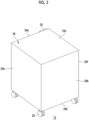
- Fig. 2 is a schematic perspective view showing an appearance of the compressor 12 according to the embodiment.
- Fig. 4 is a schematic perspective view showing the disposition of the devices inside the compressor 12 according to the embodiment.
- Figs. 2 and 3 each show a perspective view of the compressor 12 seen from a rear side.
- Fig. 3 shows a state in which some panels of the compressor casing 24 are removed in order to show the disposition of the internal devices of the compressor 12.
- the compressor casing 24 of the compressor 12 has a rectangular parallelepiped shape having six surfaces, and includes a front panel 24a, a back panel 24b, an upper panel 24c, a bottom panel 24d, and two side panels 24e and 24f on left and right sides.
- the back panel 24b faces an opposite side of the front panel 24a.
- the upper panel 24c is disposed above
- the bottom panel 24d is disposed below
- the side panels 24e and 24f are disposed on the left and right sides.
- the front panel 24a may be configured to provide a user interface and a pipe connection. Accordingly, an operation panel 25 for receiving an input for controlling the cryocooler 10 from a user of the cryocooler 10 and/or for displaying information regarding the cryocooler 10 may be provided on a front surface of the front panel 24a.
- the control device 50 may be mounted on the front panel 24a. For example, the control device 50 may be attached to a back surface of the front panel 24a.
- the front panel 24a may be provided with the discharge port 30, the suction port 31, the cooling medium intake 44, and the cooling medium discharge port 45 although the discharge port 30, the suction port 31, the cooling medium intake 44, and the cooling medium discharge port 45 are not shown in Figs. 2 and 3 because they are oriented in the opposite direction.
- Casters 52 may be attached to the bottom panel 24d in order to facilitate the movement and the transportation of the compressor 12.
- the compressor casing 24 includes a frame structure 26 that supports the above-described panels and is responsible for structural strength.
- the panels are removably attached to the frame structure 26.
- the devices inside the compressor 12 are covered and hidden by the panels as shown in Fig. 2 .
- the panels may be attached to the frame structure 26 by an appropriate method such as screwing.
- the user or the worker can easily access the devices inside the compressor 12 from an opening portion of the frame structure 26, and can efficiently perform maintenance work or manufacturing work of the compressor 12.
- a rectangular back outer frame 26a that is provided to surround the back surface and that configures a part of the frame structure 26 is provided.
- Each of four sides of the rectangular shape of the back panel 24b is removably attached to the back outer frame 26a. Both ends of an upper part of the back outer frame 26a are connected to both ends of an upper edge of the front panel 24a by two side frames 26b, and a lower part of the back outer frame 26a is connected to a rear edge of the bottom panel 24d.
- a lower edge of the front panel 24a is connected to a front edge of the bottom panel 24d.
- upper panel 24c Four sides of the upper panel 24c are removably attached to upper parts of the back outer frame 26a and the front panel 24a and the two side frames 26b.
- side panels 24e and 24f are removably attached to side portions of the back outer frame 26a and the front panel 24a, the side frame 26b, and the bottom panel 24d.
- the main components of the compressor 12, such as the compressor main body 16, the heat exchanger 22, the oil separator 34, the adsorber 35, the storage tank 36, and the control device 50, are accommodated in the compressor casing 24.
- the oil separator 34, the adsorber 35, and the storage tank 36 are installed on the bottom panel 24d close to one side panel 24e, and are disposed in the compressor casing 24.
- the adsorber 35, the storage tank 36, and the oil separator 34 are arranged in this order from the front panel 24a toward the back panel 24b.
- the compressor main body 16 and the control device 50 are disposed in the compressor casing 24 close to the other side panel 24f.
- the control device 50 may be attached to the front panel 24a, and the compressor main body 16 may be installed on the bottom panel 24d between the control device 50 and the back panel 24b.
- the heat exchanger 22 includes a double pipe 28 disposed along at least one surface of the compressor casing 24, in this embodiment, along the back surface of the compressor casing 24.
- the double pipe 28 is supported by the back outer frame 26a.
- the heat exchanger 22 is covered and hidden by the back panel 24b.
- Fig. 4 is a schematic front view of the heat exchanger 22 according to the embodiment.
- Fig. 4 shows a state in which the heat exchanger 22 and the back outer frame 26a are viewed from the inside of the compressor 12 (that is, from inside the compressor casing 24) in a state where the back panel 24b is removed.
- the double pipe 28 includes a first portion 28a and a second portion 28b.
- the first portion 28a of the double pipe 28 functions as the refrigerant gas cooler 22a of the heat exchanger 22 shown in Fig. 1
- the second portion 28b functions as the oil cooler 22b.
- a refrigerant gas inlet 54a and a first cooling medium outlet 56b are provided at one end of the first portion 28a of the double pipe 28, and a refrigerant gas outlet 54b and a first cooling medium inlet 56a are provided at the other end.
- the refrigerant gas inlet 54a is connected to the discharge port of the compressor main body 16, and the high-temperature and high-pressure refrigerant gas pressurized by the compressor main body 16 flows into the refrigerant gas cooler 22a (that is, the first portion 28a) through the refrigerant gas inlet 54a.
- the cooling medium (for example, cooling water as described above) supplied to the compressor 12 from the cooling medium intake 44 flows into the refrigerant gas cooler 22a from the first cooling medium inlet 56a, cools the refrigerant gas through heat exchange, and flows out from the first cooling medium outlet 56b.
- the refrigerant gas outlet 54b is connected to the oil separator 34, and the cooled high-pressure refrigerant gas is supplied to the oil separator through the first cooling medium outlet 56b.
- the first portion 28a of the double pipe 28 is bent along at least two adjacent sides of the back surface of the compressor casing 24, in this embodiment, along three adjacent sides. As shown in Figs. 3 and 4 , the first portion 28a is bent in a substantially C-shape along an upper side and a lateral side of the back outer frame 26a and along a rear edge of the bottom panel 24d. In this way, the first portion 28a is disposed to leave a space at a center portion of the back surface of the compressor casing 24.
- an oil inlet 58a and a second cooling medium outlet 60b are provided at one end of the second portion 28b of the double pipe 28, and an oil outlet 58b and a second cooling medium inlet 60a are provided at the other end.
- the oil inlet 58a is connected to the oil outlet of the compressor main body 16, and the oil flowing out from the compressor main body 16 flows into the oil cooler 22b (that is, the second portion 28b) through the oil inlet 58a.
- the second cooling medium inlet 60a is connected to the first cooling medium outlet 56b, and the cooling medium flows into the second portion 28b from the first portion 28a, cools the oil through heat exchange, and flows out from the second cooling medium outlet 60b.
- the second cooling medium outlet 60b is connected to the cooling medium discharge port 45, and the cooling medium used for cooling the refrigerant gas and the oil is discharged from the compressor 12 through the cooling medium discharge port 45.
- the oil outlet 58b is connected to the oil inlet of the compressor main body 16, and the cooled oil is returned to the compressor main body 16.
- the second portion 28b of the double pipe 28 is bent in a spiral shape along the back surface of the compressor casing 24.
- the second portion 28b is disposed inside the first portion 28a on the back surface of the compressor casing 24. In this way, the second portion 28b is disposed to leave a space at the center portion of the back surface of the compressor casing 24.
- An opening portion 62 in which the double pipe 28 is not disposed is formed inside the second portion 28b, that is, in the center portion of the back surface of the compressor casing 24.
- the double pipe 28 is supported by the back outer frame 26a.
- the double pipe 28 may be fixed to the back outer frame 26a by using a support material 64.
- two support materials 64 are attached to each of left and right lateral sides of the back outer frame 26a.
- One end of the support material 64 is attached to the back outer frame 26a by an appropriate method such as screwing, and the other end extends horizontally toward the opening portion 62.
- a hole into which the double pipe 28 is inserted is formed in the support material 64, and the double pipe 28 is inserted into the hole of the support material 64 and attached to the support material 64 by an appropriate method such as soldering.
- Fig. 5A is a schematic top view showing disposition of devices inside the compressor 12 according to the embodiment
- Fig. 5B is a schematic top view showing disposition of devices inside a compressor 112 according to a comparative example.
- Figs. 5A and 5B show a state in which the upper panel 24c is removed from the compressor casing 24.
- the illustration of the pipe connecting the components of the compressor 12 or 112 to each other is omitted in each drawing.
- the compressor 12 includes the compressor main body 16, the heat exchanger 22, the oil separator 34, the adsorber 35, the storage tank 36, and the control device 50.
- the compressor main body 16 and the control device 50 are disposed in a half area between the front panel 24a and the back panel 24b of the compressor casing 24, and the oil separator 34, the adsorber 35, and the storage tank 36 are disposed in the remaining half area.
- the heat exchanger 22 is disposed along the back panel 24b.
- the compressor main body 16 a heat exchanger 122, and the control device 50 are disposed in a half area between the front panel 24a and the back panel 24b of the compressor casing 24, and the oil separator 34, the adsorber 35, and the storage tank 36 are disposed in the remaining half area.
- the heat exchanger 122 is disposed between the compressor main body 16 and the control device 50, and may be, for example, a plate type heat exchanger.
- the heat exchanger 122 occupies a relatively large footprint between the compressor main body 16 and the control device 50 in order to provide a desired cooling performance. Therefore, as can be understood from the comparison between Figs. 5A and 5B , the footprint allowed for the compressor main body 16 and the control device 50 is restricted.
- the heat exchanger 22 is disposed along at least one surface of the compressor casing 24, for example, along the back surface.
- a space adjacent to a surface of the compressor casing 24 is a dead space and is not used in the existing design.
- a footprint for other devices such as the compressor main body 16 and the control device 50 can be expanded. Therefore, a degree of freedom in the disposition of the devices in the compressor 12 is increased, which is advantageous.
- the double pipe 28 of the heat exchanger 22 is bent along an outer periphery of the surface of the compressor casing 24.
- the first portion 28a is bent along at least two adjacent sides of the back surface of the compressor casing 24, and the second portion 28b is bent in a spiral shape along the back surface of the compressor casing 24.
- the bent pipe having such a shape the total length of the heat exchanger 22 can be easily increased while suppressing an increase in the footprint of the heat exchanger 22.
- the heat exchanger 22 according to the embodiment can reduce the footprint. As described above, suppressing the increase in the footprint is useful in improving the degree of freedom in the disposition of other devices inside the compressor 12. Increasing the total length of the heat exchanger 22 is helpful in improving the cooling performance of the double pipe-type heat exchanger 22.
- the heat exchanger 22 is disposed so as to leave a space at the center portion of the surface of the compressor casing 24 in which the double pipe 28 is disposed. Accordingly, the opening portion 62 in which the double pipe 28 is not disposed is formed at the center portion of the surface of the compressor casing 24.
- the worker can easily access the devices inside the compressor 12 from the opening portion 62.
- the manufacturing work such as pipe welding and joint fastening and various kinds of maintenance work (for example, replacement of consumables such as filters and replacement and repair of devices such as failed sensors) can be performed through the opening portion 62. In this way, the disposition of the double pipe 28 having a vacant center portion is useful in improving the efficiency of the manufacturing and maintenance of the compressor 12.
- the compressor casing 24 includes the frame structure 26 that is responsible for structural strength, so that each panel such as the back panel 24b attached to the frame structure 26 can be thinned and weight-saved.
- a casing structure is also useful in improving workability.
- the thinning of the panel is also useful in securing a housing space for the heat exchanger 22.
- the heat exchanger 22 is disposed along the back surface of the compressor casing 24.
- the heat exchanger 22 may be disposed along another surface (for example, an upper surface or a side surface) of the compressor casing 24.
- the heat exchanger 22 is disposed along only a single surface (that is, a back surface) of the compressor casing 24 has been described as an example, but the heat exchanger 22 can be disposed in other manners.
- the heat exchanger 22 may be disposed along at least two adjacent surfaces (for example, a back surface and an upper surface, or a back surface and a side surface) of the compressor casing 24.
- the bending shape of the double pipe 28 is not limited to the spiral shape.
- the double pipe 28 may be bent in a meandering shape along the surface of the compressor casing 24.
Landscapes
- Engineering & Computer Science (AREA)
- Mechanical Engineering (AREA)
- General Engineering & Computer Science (AREA)
- Physics & Mathematics (AREA)
- Thermal Sciences (AREA)
- Compressor (AREA)
Abstract
The task is to propose heat exchanger disposition that enables reduction in footprint of a heat exchanger (22) in a cryocooler compressor (12). A cryocooler compressor (12) includes a compressor casing (24); and a double pipe-type heat exchanger (22) that is accommodated in the compressor casing (24) and cools the compressor (12). The double pipe-type heat exchanger (22) includes a double pipe (28) disposed along at least one surface of the compressor casing (24). The double pipe (28) is spirally bent along the at least one surface of the compressor casing (24). The double pipe (28) is bent along at least two adjacent sides of the at least one surface of the compressor casing (24).
Description
- The present invention relates to a cryocooler compressor.
- In general, a cryocooler such as a Gifford-McMahon (GM) cryocooler includes a compressor of a refrigerant gas to supply a high-pressure refrigerant gas to a cold head. The compressor includes components such as a compressor main body, an oil separator, an adsorber, a storage tank, and a control device (for example,
Japanese Unexamined Patent Publication No. 2001-74326 - In addition to the above-described components, the compressor for the cryocooler is usually provided with a heat exchanger the cools the compressor. These components of the compressor are accommodated in a compressor casing. In the existing design, the heat exchanger occupies a relatively large footprint in the compressor casing. Therefore, in aiming for miniaturization of the compressor, the heat exchanger may be one of obstacles.
- An exemplary object of one embodiment of the present invention is to propose heat exchanger disposition that enables reduction in footprint of the heat exchanger in the cryocooler compressor.
- According to an aspect of the present invention, there is provided a cryocooler compressor including a compressor casing and a double pipe-type heat exchanger that is accommodated in the compressor casing and cools the compressor. The double pipe-type heat exchanger includes a double pipe disposed along at least one surface of the compressor casing.
- According to the present invention, it is possible to provide heat exchanger disposition that enables reduction in footprint of the heat exchanger in the cryocooler compressor.
-
-
Fig. 1 is a diagram schematically showing a cryocooler according to an embodiment. -
Fig. 2 is a schematic perspective view showing an appearance of a compressor according to the embodiment. -
Fig. 3 is a schematic perspective view showing disposition of devices inside the compressor according to the embodiment. -
Fig. 4 is a schematic front view of a heat exchanger according to the embodiment. -
Fig. 5A is a schematic top view showing disposition of devices inside the compressor according to the embodiment, andFig. 5B is a schematic top view showing disposition of devices inside a compressor according to a comparative example. - Hereinafter, an embodiment for carrying out the present invention will be described in detail with reference to the drawings. In the description and the drawings, the same or equivalent components, members, and processes are denoted by the same reference numerals, and overlapping description is omitted as appropriate. The scale and the shape of each of parts shown in the drawings are set for convenience to make the description easy to understand, and are not to be interpreted as limiting unless stated otherwise. The embodiment is merely an example and does not limit the scope of the present invention. All features described in the embodiment or combinations thereof are not necessarily essential to the present invention.
-
Fig. 1 is a diagram schematically showing acryocooler 10 according to the embodiment. Thecryocooler 10 is used to provide cryogenic cooling to an object or a medium. For example, thecryocooler 10 may be used as a cooling source for a superconducting magnet device. The superconducting magnet device is mounted on, for example, a high magnetic field using device as a magnetic field source of an accelerator such as a single crystal pulling device, a nuclear magnetic resonance (NMR) system, a magnetic resonance imaging (MRI) system, and a cyclotron, a high energy physical system such as a nuclear fusion system, or other high magnetic field using devices (not shown) and can generate a high magnetic field required for the devices. - The
cryocooler 10 includes acompressor 12 and acold head 14. Thecompressor 12 is configured to collect a refrigerant gas of thecryocooler 10 from thecold head 14, to pressurize the collected refrigerant gas, and to supply the refrigerant gas to thecold head 14 again. Thecompressor 12 is also referred to as a compressor unit. Thecold head 14 is also referred to as an expander and includes aroom temperature section 14a and a low-temperature section 14b which is also referred to as a cooling stage. The refrigerant gas is also referred to as a working gas, and other suitable gases may be used although a helium gas is typically used. Thecompressor 12 and thecold head 14 constitute a refrigeration cycle of thecryocooler 10, whereby the low-temperature section 14b is cooled to a desired cryogenic temperature. The low-temperature section 14b can cool an object to be cooled such as a superconducting magnet. - Although the
cryocooler 10 is, for example, a single-stage or two-stage Gifford-McMahon (GM) cryocooler, thecryocooler 10 may be a pulse tube cryocooler, a Stirling cryocooler, or other types of cryocoolers. Although thecold head 14 has a different configuration depending on the type of thecryocooler 10, thecompressor 12 can use a configuration described below regardless of the type of thecryocooler 10. - In general, both a pressure of a refrigerant gas supplied from the
compressor 12 to thecold head 14 and a pressure of a refrigerant gas collected from thecold head 14 to thecompressor 12 are considerably higher than the atmospheric pressure, and can be called a first high pressure and a second high pressure, respectively. For convenience of description, the first high pressure and the second high pressure are also simply called a high pressure and a low pressure, respectively. Typically, the high pressure is, for example, 2 to 3 MPa. The low pressure is, for example, 0.5 to 1.5 MPa and is, for example, about 0.8 MPa. - The
compressor 12 is an oil-lubricated cryocooler compressor, and includes a compressormain body 16, arefrigerant gas line 18, and anoil circulation line 20. InFig. 1 , in order to facilitate understanding, therefrigerant gas line 18 is shown by a solid line, and theoil circulation line 20 is shown by a broken line. In addition, thecompressor 12 includes acompressor casing 24 that accommodates each component of thecompressor 12, such as the compressormain body 16, therefrigerant gas line 18, and theoil circulation line 20. - The compressor
main body 16 is configured to internally compress a refrigerant gas sucked from a suction port of the compressormain body 16 and to discharge the refrigerant gas from a discharge port. An oil is used in the compressormain body 16 for the sake of cooling and lubrication, and the sucked refrigerant gas is directly exposed to the oil in the compressormain body 16. Accordingly, the refrigerant gas is delivered from the discharge port in a state where the oil is slightly mixed. - The compressor
main body 16 may be, for example, a scroll type pump, a rotary type pump, or other pumps that pressurize a refrigerant gas. The compressormain body 16 may be configured to discharge the refrigerant gas at a fixed and constant flow rate. Alternatively, the compressormain body 16 may be configured to vary the flow rate of the refrigerant gas to be discharged. The compressormain body 16 may be called a compression capsule. - The
refrigerant gas line 18 includes adischarge port 30, asuction port 31, adischarge flow path 32, and asuction flow path 33. Thedischarge port 30 is an outlet of a refrigerant gas that is installed in thecompressor casing 24 in order to deliver the refrigerant gas, which is pressurized to a high pressure by the compressormain body 16, from thecompressor 12, and thesuction port 31 is an inlet of the refrigerant gas that is installed in thecompressor casing 24 in order for thecompressor 12 to receive a low-pressure refrigerant gas. Thecompressor casing 24 accommodates thedischarge flow path 32 and thesuction flow path 33. The discharge port of the compressormain body 16 is connected to thedischarge port 30 by thedischarge flow path 32, and thesuction port 31 is connected to the suction port of the compressormain body 16 by thesuction flow path 33. - The
refrigerant gas line 18 is connected to thecold head 14. A high-pressure port 40 and a low-pressure port 41 are provided in theroom temperature section 14a of thecold head 14. The high-pressure port 40 is connected to thedischarge port 30 by a high-pressure pipe 42, and the low-pressure port 41 is connected to thesuction port 31 by a low-pressure pipe 43. - The
oil separator 34 and theadsorber 35 are provided in thedischarge flow path 32. Theoil separator 34 is provided in order to separate an oil, which is mixed in a refrigerant gas as passing through the compressormain body 16, out from the refrigerant gas. Theadsorber 35 is provided in order to remove, for example, a vaporized oil and other contaminants remaining in the refrigerant gas from the refrigerant gas through adsorption. Theoil separator 34 and theadsorber 35 are connected in series. In thedischarge flow path 32, theoil separator 34 is disposed on the compressormain body 16 side, and theadsorber 35 is disposed on thedischarge port 30 side. - An
oil return line 21 that connects theoil separator 34 to the compressormain body 16 is provided. An oil collected by theoil separator 34 can be returned to the compressormain body 16 through theoil return line 21. In the middle of theoil return line 21, a filter that removes dust included in the oil separated out by theoil separator 34 and an orifice that controls the amount of the oil returning to the compressormain body 16 may be provided. - On the other hand, a
storage tank 36 is provided at thesuction flow path 33. Thestorage tank 36 is provided as a volume for removing pulsation included in a low-pressure refrigerant gas returning from thecold head 14 to thecompressor 12. - In addition, a
bypass valve 38 that connects thedischarge flow path 32 to thesuction flow path 33 to bypass the compressormain body 16 is provided at therefrigerant gas line 18. For example, thebypass valve 38 branches off from thedischarge flow path 32 between theoil separator 34 and theadsorber 35 and is connected to thesuction flow path 33 between the compressormain body 16 and thestorage tank 36. Thebypass valve 38 is provided in order to control a flow rate of a refrigerant gas and/or in order to equalize thedischarge flow path 32 and thesuction flow path 33 when thecompressor 12 is stopped. - The
oil circulation line 20 connects an oil outlet to an oil inlet of the compressormain body 16 in order to return the oil flowing out from the compressormain body 16 to the compressormain body 16 again. Theoil circulation line 20 may be provided with an orifice that controls a flow rate of an oil flowing therein. In addition, a filter that removes dust included in the oil may be provided at theoil circulation line 20. - In addition, the
compressor 12 further includes aheat exchanger 22 that is accommodated in thecompressor casing 24 and cools thecompressor 12. Theheat exchanger 22 includes a refrigerant gas cooler 22a that cools therefrigerant gas line 18 through heat exchange between the refrigerant gas and a cooling medium, and an oil cooler 22b that cools theoil circulation line 20 through heat exchange between the oil and the cooling medium. - The refrigerant gas cooler 22a is disposed between the compressor
main body 16 and theoil separator 34 in thedischarge flow path 32, and cools a high-pressure refrigerant gas heated by compression heat generated with the compression of the refrigerant gas in the compressormain body 16. The refrigerant gas cooler 22a cools the refrigerant gas through heat exchange between the refrigerant gas and the cooling medium. The cooled refrigerant gas is purified by theoil separator 34 and theadsorber 35. In addition, the oil cooler 22b cools the oil through heat exchange between the oil flowing out from the oil outlet of the compressormain body 16 to theoil circulation line 20 and the cooling medium. The cooled oil is returned into the compressormain body 16 from the oil inlet of the compressormain body 16. The cooling medium is supplied from the outside to thecompressor 12 through a coolingmedium intake 44, and is discharged to the outside of thecompressor 12 from a coolingmedium discharge port 45 via the refrigerant gas cooler 22a and the oil cooler 22b. The cooling medium may be a coolant, for example, water. In this manner, compression heat generated by the compressormain body 16 is removed to the outside of thecompressor 12 together with the cooling medium. The cooling medium may be cooled by, for example, a chiller (not shown) and may be supplied again. - In this embodiment, the
heat exchanger 22 is a double pipe-type heat exchanger. Therefore, theheat exchanger 22 includes an outer tube and an inner tube inserted into the outer tube. The cooling medium is supplied to one of the outer tube and the inner tube, a fluid to be cooled is supplied to the other. Accordingly, heat exchange between the cooling medium and the target fluid is performed, and the fluid can be cooled. For example, in the refrigerant gas cooler 22a, cooling water may be supplied to the outer tube, and the refrigerant gas may be supplied to the inner tube. In the oil cooler 22b, cooling water may be supplied to the outer tube, and oil may be supplied to the inner tube. - In addition, the
compressor casing 24 may accommodate acontrol device 50 for controlling thecryocooler 10. Thecontrol device 50 may include a control circuit configured to receive an output from various sensors provided in thecryocooler 10 and to control various devices of thecryocooler 10 based on the sensor output. The sensor may include, for example, a refrigerant gas temperature sensor and a refrigerant gas pressure sensor provided in therefrigerant gas line 18, an oil temperature sensor provided in theoil circulation line 20, or a cooling temperature sensor provided in the low-temperature section 14b of thecold head 14. The device controlled based on the sensor output may include, for example, a compressor motor that drives the compressormain body 16, thebypass valve 38, and a cold head motor that drives thecold head 14. Thecontrol device 50 may include a compressor inverter for controlling a rotation speed of the compressor motor and/or a cold head inverter for controlling a rotation speed of the cold head motor. - During an operation of the
cryocooler 10, a refrigerant gas is supplied from thecompressor 12 to thecold head 14, a refrigeration cycle (for example, a GM cycle) is configured by a periodic volume fluctuation of an expansion space of the refrigerant gas in thecold head 14 and a pressure fluctuation of the refrigerant gas in the expansion space synchronized with the periodic volume fluctuation, and the low-temperature section 14b of thecold head 14 is cooled to a desired cryogenic temperature. In a case where thecold head 14 is, for example, a two-stage type, a first-stage cooling stage is cooled to a first cooling temperature in a range of, for example, about 30 K to about 80 K, and a second-stage cooling stage is cooled to a second cooling temperature lower than the first cooling temperature, for example, 1 K to 20 K. The second cooling temperature may be a liquid helium temperature of about 4.2 K or a temperature lower than the liquid helium temperature. - A refrigerant gas collected from the
cold head 14 to thecompressor 12 flows into thesuction port 31 of thecompressor 12 from the low-pressure port 41 through the low-pressure pipe 43. The refrigerant gas is collected to the suction port of the compressormain body 16 via thestorage tank 36 on thesuction flow path 33. The refrigerant gas is compressed and pressurized by the compressormain body 16. In this case, a temperature of the refrigerant gas is raised by compression heat. The refrigerant gas delivered from the discharge port of the compressormain body 16 is cooled by the refrigerant gas cooler 22a of theheat exchanger 22, and exits thecompressor 12 from thedischarge port 30 via theoil separator 34 and theadsorber 35. The refrigerant gas is supplied into thecold head 14 via the high-pressure pipe 42 and the high-pressure port 40. -
Fig. 2 is a schematic perspective view showing an appearance of thecompressor 12 according to the embodiment.Fig. 4 is a schematic perspective view showing the disposition of the devices inside thecompressor 12 according to the embodiment.Figs. 2 and3 each show a perspective view of thecompressor 12 seen from a rear side.Fig. 3 shows a state in which some panels of thecompressor casing 24 are removed in order to show the disposition of the internal devices of thecompressor 12. - As shown in
Fig. 2 , thecompressor casing 24 of thecompressor 12 has a rectangular parallelepiped shape having six surfaces, and includes afront panel 24a, aback panel 24b, anupper panel 24c, abottom panel 24d, and twoside panels back panel 24b faces an opposite side of thefront panel 24a. Between thefront panel 24a and theback panel 24b, theupper panel 24c is disposed above, thebottom panel 24d is disposed below, and theside panels - The
front panel 24a may be configured to provide a user interface and a pipe connection. Accordingly, anoperation panel 25 for receiving an input for controlling thecryocooler 10 from a user of thecryocooler 10 and/or for displaying information regarding thecryocooler 10 may be provided on a front surface of thefront panel 24a. Thecontrol device 50 may be mounted on thefront panel 24a. For example, thecontrol device 50 may be attached to a back surface of thefront panel 24a. In addition, thefront panel 24a may be provided with thedischarge port 30, thesuction port 31, the coolingmedium intake 44, and the coolingmedium discharge port 45 although thedischarge port 30, thesuction port 31, the coolingmedium intake 44, and the coolingmedium discharge port 45 are not shown inFigs. 2 and3 because they are oriented in the opposite direction. -
Casters 52 may be attached to thebottom panel 24d in order to facilitate the movement and the transportation of thecompressor 12. - As shown in
Fig. 3 , thecompressor casing 24 includes aframe structure 26 that supports the above-described panels and is responsible for structural strength. The panels are removably attached to theframe structure 26. In a state where the panels are attached to theframe structure 26, the devices inside thecompressor 12 are covered and hidden by the panels as shown inFig. 2 . The panels may be attached to theframe structure 26 by an appropriate method such as screwing. In a state where the panels are removed from theframe structure 26, the user or the worker can easily access the devices inside thecompressor 12 from an opening portion of theframe structure 26, and can efficiently perform maintenance work or manufacturing work of thecompressor 12. - For example, on a back surface of the
compressor casing 24, a rectangular backouter frame 26a that is provided to surround the back surface and that configures a part of theframe structure 26 is provided. Each of four sides of the rectangular shape of theback panel 24b is removably attached to the backouter frame 26a. Both ends of an upper part of the backouter frame 26a are connected to both ends of an upper edge of thefront panel 24a by twoside frames 26b, and a lower part of the backouter frame 26a is connected to a rear edge of thebottom panel 24d. In addition, a lower edge of thefront panel 24a is connected to a front edge of thebottom panel 24d. Four sides of theupper panel 24c are removably attached to upper parts of the backouter frame 26a and thefront panel 24a and the twoside frames 26b. Four sides of theside panels outer frame 26a and thefront panel 24a, theside frame 26b, and thebottom panel 24d. - As described above, the main components of the
compressor 12, such as the compressormain body 16, theheat exchanger 22, theoil separator 34, theadsorber 35, thestorage tank 36, and thecontrol device 50, are accommodated in thecompressor casing 24. Theoil separator 34, theadsorber 35, and thestorage tank 36 are installed on thebottom panel 24d close to oneside panel 24e, and are disposed in thecompressor casing 24. Theadsorber 35, thestorage tank 36, and theoil separator 34 are arranged in this order from thefront panel 24a toward theback panel 24b. In addition, the compressormain body 16 and thecontrol device 50 are disposed in thecompressor casing 24 close to theother side panel 24f. As described above, thecontrol device 50 may be attached to thefront panel 24a, and the compressormain body 16 may be installed on thebottom panel 24d between thecontrol device 50 and theback panel 24b. - The
heat exchanger 22 includes adouble pipe 28 disposed along at least one surface of thecompressor casing 24, in this embodiment, along the back surface of thecompressor casing 24. Thedouble pipe 28 is supported by the backouter frame 26a. When theback panel 24b is attached to the backouter frame 26a, theheat exchanger 22 is covered and hidden by theback panel 24b. -
Fig. 4 is a schematic front view of theheat exchanger 22 according to the embodiment.Fig. 4 shows a state in which theheat exchanger 22 and the backouter frame 26a are viewed from the inside of the compressor 12 (that is, from inside the compressor casing 24) in a state where theback panel 24b is removed. - As shown in
Figs. 3 and4 , thedouble pipe 28 includes afirst portion 28a and asecond portion 28b. Thefirst portion 28a of thedouble pipe 28 functions as the refrigerant gas cooler 22a of theheat exchanger 22 shown inFig. 1 , and thesecond portion 28b functions as the oil cooler 22b. - As shown in
Fig. 4 , arefrigerant gas inlet 54a and a firstcooling medium outlet 56b are provided at one end of thefirst portion 28a of thedouble pipe 28, and arefrigerant gas outlet 54b and a firstcooling medium inlet 56a are provided at the other end. As shown inFig. 1 , therefrigerant gas inlet 54a is connected to the discharge port of the compressormain body 16, and the high-temperature and high-pressure refrigerant gas pressurized by the compressormain body 16 flows into the refrigerant gas cooler 22a (that is, thefirst portion 28a) through therefrigerant gas inlet 54a. The cooling medium (for example, cooling water as described above) supplied to thecompressor 12 from the coolingmedium intake 44 flows into the refrigerant gas cooler 22a from the firstcooling medium inlet 56a, cools the refrigerant gas through heat exchange, and flows out from the firstcooling medium outlet 56b. Therefrigerant gas outlet 54b is connected to theoil separator 34, and the cooled high-pressure refrigerant gas is supplied to the oil separator through the firstcooling medium outlet 56b. - The
first portion 28a of thedouble pipe 28 is bent along at least two adjacent sides of the back surface of thecompressor casing 24, in this embodiment, along three adjacent sides. As shown inFigs. 3 and4 , thefirst portion 28a is bent in a substantially C-shape along an upper side and a lateral side of the backouter frame 26a and along a rear edge of thebottom panel 24d. In this way, thefirst portion 28a is disposed to leave a space at a center portion of the back surface of thecompressor casing 24. - In addition, an
oil inlet 58a and a secondcooling medium outlet 60b are provided at one end of thesecond portion 28b of thedouble pipe 28, and anoil outlet 58b and a secondcooling medium inlet 60a are provided at the other end. As shown inFig. 1 , theoil inlet 58a is connected to the oil outlet of the compressormain body 16, and the oil flowing out from the compressormain body 16 flows into the oil cooler 22b (that is, thesecond portion 28b) through theoil inlet 58a. As shown inFig. 4 , the secondcooling medium inlet 60a is connected to the firstcooling medium outlet 56b, and the cooling medium flows into thesecond portion 28b from thefirst portion 28a, cools the oil through heat exchange, and flows out from the secondcooling medium outlet 60b. As shown inFig. 1 , the secondcooling medium outlet 60b is connected to the coolingmedium discharge port 45, and the cooling medium used for cooling the refrigerant gas and the oil is discharged from thecompressor 12 through the coolingmedium discharge port 45. Theoil outlet 58b is connected to the oil inlet of the compressormain body 16, and the cooled oil is returned to the compressormain body 16. - The
second portion 28b of thedouble pipe 28 is bent in a spiral shape along the back surface of thecompressor casing 24. Thesecond portion 28b is disposed inside thefirst portion 28a on the back surface of thecompressor casing 24. In this way, thesecond portion 28b is disposed to leave a space at the center portion of the back surface of thecompressor casing 24. An openingportion 62 in which thedouble pipe 28 is not disposed is formed inside thesecond portion 28b, that is, in the center portion of the back surface of thecompressor casing 24. - The
double pipe 28 is supported by the backouter frame 26a. As an example, as shown inFig. 4 , thedouble pipe 28 may be fixed to the backouter frame 26a by using asupport material 64. In this example, twosupport materials 64 are attached to each of left and right lateral sides of the backouter frame 26a. One end of thesupport material 64 is attached to the backouter frame 26a by an appropriate method such as screwing, and the other end extends horizontally toward the openingportion 62. A hole into which thedouble pipe 28 is inserted is formed in thesupport material 64, and thedouble pipe 28 is inserted into the hole of thesupport material 64 and attached to thesupport material 64 by an appropriate method such as soldering. -
Fig. 5A is a schematic top view showing disposition of devices inside thecompressor 12 according to the embodiment, andFig. 5B is a schematic top view showing disposition of devices inside acompressor 112 according to a comparative example.Figs. 5A and 5B show a state in which theupper panel 24c is removed from thecompressor casing 24. In addition, for the sake of simplicity, the illustration of the pipe connecting the components of thecompressor - As described above, the
compressor 12 includes the compressormain body 16, theheat exchanger 22, theoil separator 34, theadsorber 35, thestorage tank 36, and thecontrol device 50. As shown inFig. 5A , the compressormain body 16 and thecontrol device 50 are disposed in a half area between thefront panel 24a and theback panel 24b of thecompressor casing 24, and theoil separator 34, theadsorber 35, and thestorage tank 36 are disposed in the remaining half area. Theheat exchanger 22 is disposed along theback panel 24b. - On the other hand, in the
compressor 112 of the existing design shown inFig. 5B , the compressormain body 16, aheat exchanger 122, and thecontrol device 50 are disposed in a half area between thefront panel 24a and theback panel 24b of thecompressor casing 24, and theoil separator 34, theadsorber 35, and thestorage tank 36 are disposed in the remaining half area. Theheat exchanger 122 is disposed between the compressormain body 16 and thecontrol device 50, and may be, for example, a plate type heat exchanger. - In the disposition of the devices of the
compressor 112 shown inFig. 5B , theheat exchanger 122 occupies a relatively large footprint between the compressormain body 16 and thecontrol device 50 in order to provide a desired cooling performance. Therefore, as can be understood from the comparison betweenFigs. 5A and 5B , the footprint allowed for the compressormain body 16 and thecontrol device 50 is restricted. - On the other hand, according to the embodiment, as shown in
Fig. 5A , theheat exchanger 22 is disposed along at least one surface of thecompressor casing 24, for example, along the back surface. A space adjacent to a surface of thecompressor casing 24 is a dead space and is not used in the existing design. By using this space to house theheat exchanger 22, a footprint for other devices such as the compressormain body 16 and thecontrol device 50 can be expanded. Therefore, a degree of freedom in the disposition of the devices in thecompressor 12 is increased, which is advantageous. In addition, in recent years, there is a tendency to require a large-sized control device 50 to be mounted on thecompressor 12 in order to implement advanced control. According to the embodiment, in response to such a requirement, it is easy and advantageous to secure sufficient space for installation of thecontrol device 50. - In addition, according to the embodiment, the
double pipe 28 of theheat exchanger 22 is bent along an outer periphery of the surface of thecompressor casing 24. For example, as described above, thefirst portion 28a is bent along at least two adjacent sides of the back surface of thecompressor casing 24, and thesecond portion 28b is bent in a spiral shape along the back surface of thecompressor casing 24. By using the bent pipe having such a shape, the total length of theheat exchanger 22 can be easily increased while suppressing an increase in the footprint of theheat exchanger 22. In particular, compared to the plate type heat exchanger that can be mounted on the existing compressor, theheat exchanger 22 according to the embodiment can reduce the footprint. As described above, suppressing the increase in the footprint is useful in improving the degree of freedom in the disposition of other devices inside thecompressor 12. Increasing the total length of theheat exchanger 22 is helpful in improving the cooling performance of the double pipe-type heat exchanger 22. - According to the embodiment, the
heat exchanger 22 is disposed so as to leave a space at the center portion of the surface of thecompressor casing 24 in which thedouble pipe 28 is disposed. Accordingly, the openingportion 62 in which thedouble pipe 28 is not disposed is formed at the center portion of the surface of thecompressor casing 24. In the manufacturing process of thecompressor 12 or in maintenance work of thecompressor 12 at a site where thecompressor 12 is used, the worker can easily access the devices inside thecompressor 12 from the openingportion 62. For example, the manufacturing work such as pipe welding and joint fastening and various kinds of maintenance work (for example, replacement of consumables such as filters and replacement and repair of devices such as failed sensors) can be performed through the openingportion 62. In this way, the disposition of thedouble pipe 28 having a vacant center portion is useful in improving the efficiency of the manufacturing and maintenance of thecompressor 12. - In the existing compressor, a design is adopted in which a panel itself forming each surface of the compressor casing is responsible for structural strength, so that a plate thickness of the panel is large, and a weight thereof tends to be large. Therefore, the work of attaching the panel in the manufacturing process or the work of removing the panel in the maintenance work is not easy, which is one of causes of a decrease in workability for the worker.
- On the other hand, according to the embodiment, the
compressor casing 24 includes theframe structure 26 that is responsible for structural strength, so that each panel such as theback panel 24b attached to theframe structure 26 can be thinned and weight-saved. Such a casing structure is also useful in improving workability. In addition, the thinning of the panel is also useful in securing a housing space for theheat exchanger 22. - The present invention has been described above based on the examples. It will be understood by those skilled in the art that the present invention is not limited to the embodiment, various modification examples are possible, and such modification examples are also within the scope of the present invention. Various features described concerning a certain embodiment are also applicable to other embodiments. A new embodiment resulting from combinations also has the effects of each of the combined embodiments.
- In the above-described embodiment, the
heat exchanger 22 is disposed along the back surface of thecompressor casing 24. However, this is an example, and the present invention is not limited thereto. Theheat exchanger 22 may be disposed along another surface (for example, an upper surface or a side surface) of thecompressor casing 24. - In addition, in the above-described embodiment, a case where the
heat exchanger 22 is disposed along only a single surface (that is, a back surface) of thecompressor casing 24 has been described as an example, but theheat exchanger 22 can be disposed in other manners. For example, theheat exchanger 22 may be disposed along at least two adjacent surfaces (for example, a back surface and an upper surface, or a back surface and a side surface) of thecompressor casing 24. - The bending shape of the
double pipe 28 is not limited to the spiral shape. For example, thedouble pipe 28 may be bent in a meandering shape along the surface of thecompressor casing 24. - Although the present invention has been described using specific words and phrases based on the embodiment, the embodiment merely shows one aspect of the principle and application of the present invention, and various modifications and improvements can be made within the scope of the present invention described in claims.
-
- 10
- cryocooler
- 12
- compressor
- 22
- heat exchanger
- 24
- compressor casing
- 24b
- back panel
- 26a
- back outer frame
- 28
- double pipe
Claims (7)
- A cryocooler compressor (12) comprising:a compressor casing (24); anda double pipe-type heat exchanger (22) that is accommodated in the compressor casing (24) and cools the compressor (12),wherein the double pipe-type heat exchanger (22) includes a double pipe (28) disposed along at least one surface of the compressor casing (24).
- The cryocooler compressor (12) according to claim 1,
wherein the double pipe (28) is spirally bent along the at least one surface of the compressor casing (24). - The cryocooler compressor (12) according to claim 2,
wherein the double pipe (28) is disposed to leave a space at a center portion of the at least one surface of the compressor casing (24). - The cryocooler compressor (12) according to claim 1,
wherein the double pipe (28) is bent along at least two adjacent sides of the at least one surface of the compressor casing (24). - The cryocooler compressor (12) according to claim 4,
wherein the double pipe (28) is disposed to leave a space at a center portion of the at least one surface of the compressor casing (24). - The cryocooler compressor (12) according to any one of claims 1 to 5,
wherein the at least one surface includes a back surface of the compressor casing (24). - The cryocooler compressor (12) according to claim 6,
wherein the compressor casing (24) includes a back outer frame (26a) that is provided to surround the back surface and supports the double pipe (28), and a back panel (24b) that is removably attached to the back outer frame (26a) to cover and hide the double pipe-type heat exchanger (22) .
Applications Claiming Priority (1)
| Application Number | Priority Date | Filing Date | Title |
|---|---|---|---|
| JP2023101014A JP2025001425A (en) | 2023-06-20 | 2023-06-20 | Compressor for cryogenic refrigerating machine |
Publications (1)
| Publication Number | Publication Date |
|---|---|
| EP4481299A1 true EP4481299A1 (en) | 2024-12-25 |
Family
ID=91375912
Family Applications (1)
| Application Number | Title | Priority Date | Filing Date |
|---|---|---|---|
| EP24179567.3A Pending EP4481299A1 (en) | 2023-06-20 | 2024-06-03 | Cryocooler compressor |
Country Status (4)
| Country | Link |
|---|---|
| US (1) | US20240426526A1 (en) |
| EP (1) | EP4481299A1 (en) |
| JP (1) | JP2025001425A (en) |
| CN (2) | CN119163587A (en) |
Citations (4)
| Publication number | Priority date | Publication date | Assignee | Title |
|---|---|---|---|---|
| JP2001074326A (en) | 1999-09-07 | 2001-03-23 | Daikin Ind Ltd | Compressor unit |
| KR101397944B1 (en) * | 2012-07-24 | 2014-05-27 | 김용범 | Cryocooler type freezer |
| WO2022176652A1 (en) * | 2021-02-22 | 2022-08-25 | 住友重機械工業株式会社 | Compressor for ultra-low-temperature freezer, and adsorber unit |
| US11649990B2 (en) * | 2020-02-28 | 2023-05-16 | Sumitomo Heavy Industries, Ltd. | Compressor system for cryocooler and auxiliary cooling device |
-
2023
- 2023-06-20 JP JP2023101014A patent/JP2025001425A/en active Pending
-
2024
- 2024-06-03 EP EP24179567.3A patent/EP4481299A1/en active Pending
- 2024-06-12 CN CN202410751965.8A patent/CN119163587A/en active Pending
- 2024-06-12 CN CN202421328679.2U patent/CN222615520U/en active Active
- 2024-06-13 US US18/742,971 patent/US20240426526A1/en active Pending
Patent Citations (4)
| Publication number | Priority date | Publication date | Assignee | Title |
|---|---|---|---|---|
| JP2001074326A (en) | 1999-09-07 | 2001-03-23 | Daikin Ind Ltd | Compressor unit |
| KR101397944B1 (en) * | 2012-07-24 | 2014-05-27 | 김용범 | Cryocooler type freezer |
| US11649990B2 (en) * | 2020-02-28 | 2023-05-16 | Sumitomo Heavy Industries, Ltd. | Compressor system for cryocooler and auxiliary cooling device |
| WO2022176652A1 (en) * | 2021-02-22 | 2022-08-25 | 住友重機械工業株式会社 | Compressor for ultra-low-temperature freezer, and adsorber unit |
Also Published As
| Publication number | Publication date |
|---|---|
| CN222615520U (en) | 2025-03-14 |
| JP2025001425A (en) | 2025-01-08 |
| CN119163587A (en) | 2024-12-20 |
| US20240426526A1 (en) | 2024-12-26 |
Similar Documents
| Publication | Publication Date | Title |
|---|---|---|
| US20030177782A1 (en) | Method for increasing efficiency of a vapor compression system by evaporator heating | |
| CN114739031B (en) | A dilution refrigeration system | |
| JP2012057920A (en) | Cryopump and cryogenic refrigerator | |
| WO2020149214A1 (en) | Method for starting cryogenic freezer and cryogenic freezer | |
| JP2012255590A (en) | Cryopump, and cryogenic refrigerator | |
| US20240093916A1 (en) | Dilution refrigeration device and method | |
| EP4481299A1 (en) | Cryocooler compressor | |
| JP2003194428A (en) | Cooling device | |
| EP4481197B1 (en) | Cryocooler compressor | |
| US20250043999A1 (en) | Oil lubrication-type compressor for cryocooler | |
| US7143587B2 (en) | Low frequency pulse tube system with oil-free drive | |
| JP2001174102A (en) | Air conditioner | |
| EP4596876A1 (en) | Compressor unit of cryocooler | |
| JP2011075254A (en) | Turbo refrigerator | |
| EP4729776A1 (en) | Compressor for cryocooler and compressor casing for cryocooler | |
| JP3278927B2 (en) | Helium refrigerator | |
| JP2003294350A (en) | Cooling system | |
| EP4357696B1 (en) | Oil-lubricated cryocooler compressor and operation method thereof | |
| EP4467896A1 (en) | Cryocooler and method for operating cryocooler | |
| CN223992360U (en) | JT throttling refrigeration system driven by superconducting direct-current linear compressor | |
| US7165406B2 (en) | Integral pulse tube refrigerator and cryopump | |
| JP2026074780A (en) | Cryogenic refrigerator compressor and cryogenic refrigerator compressor housing | |
| CN120140975A (en) | JT Throttling Refrigeration System Driven by Superconducting DC Linear Compressor | |
| CN118423283A (en) | Compressor with a compressor body having a rotor with a rotor shaft | |
| CN113294939A (en) | Composite fluid refrigeration equipment and fluid circulation system thereof |
Legal Events
| Date | Code | Title | Description |
|---|---|---|---|
| PUAI | Public reference made under article 153(3) epc to a published international application that has entered the european phase |
Free format text: ORIGINAL CODE: 0009012 |
|
| STAA | Information on the status of an ep patent application or granted ep patent |
Free format text: STATUS: EXAMINATION IS IN PROGRESS |
|
| 17P | Request for examination filed |
Effective date: 20240603 |
|
| AK | Designated contracting states |
Kind code of ref document: A1 Designated state(s): AL AT BE BG CH CY CZ DE DK EE ES FI FR GB GR HR HU IE IS IT LI LT LU LV MC ME MK MT NL NO PL PT RO RS SE SI SK SM TR |