EP4481198A1 - Heat pump and method of securing a heat pump for transport - Google Patents
Heat pump and method of securing a heat pump for transport Download PDFInfo
- Publication number
- EP4481198A1 EP4481198A1 EP23181112.6A EP23181112A EP4481198A1 EP 4481198 A1 EP4481198 A1 EP 4481198A1 EP 23181112 A EP23181112 A EP 23181112A EP 4481198 A1 EP4481198 A1 EP 4481198A1
- Authority
- EP
- European Patent Office
- Prior art keywords
- compressor
- housing
- securing member
- heat pump
- opening
- Prior art date
- Legal status (The legal status is an assumption and is not a legal conclusion. Google has not performed a legal analysis and makes no representation as to the accuracy of the status listed.)
- Pending
Links
Images



Classifications
-
- F—MECHANICAL ENGINEERING; LIGHTING; HEATING; WEAPONS; BLASTING
- F04—POSITIVE - DISPLACEMENT MACHINES FOR LIQUIDS; PUMPS FOR LIQUIDS OR ELASTIC FLUIDS
- F04B—POSITIVE-DISPLACEMENT MACHINES FOR LIQUIDS; PUMPS
- F04B39/00—Component parts, details, or accessories, of pumps or pumping systems specially adapted for elastic fluids, not otherwise provided for in, or of interest apart from, groups F04B25/00 - F04B37/00
- F04B39/0027—Pulsation and noise damping means
- F04B39/0044—Pulsation and noise damping means with vibration damping supports
-
- F—MECHANICAL ENGINEERING; LIGHTING; HEATING; WEAPONS; BLASTING
- F04—POSITIVE - DISPLACEMENT MACHINES FOR LIQUIDS; PUMPS FOR LIQUIDS OR ELASTIC FLUIDS
- F04B—POSITIVE-DISPLACEMENT MACHINES FOR LIQUIDS; PUMPS
- F04B39/00—Component parts, details, or accessories, of pumps or pumping systems specially adapted for elastic fluids, not otherwise provided for in, or of interest apart from, groups F04B25/00 - F04B37/00
- F04B39/12—Casings; Cylinders; Cylinder heads; Fluid connections
-
- F—MECHANICAL ENGINEERING; LIGHTING; HEATING; WEAPONS; BLASTING
- F24—HEATING; RANGES; VENTILATING
- F24F—AIR-CONDITIONING; AIR-HUMIDIFICATION; VENTILATION; USE OF AIR CURRENTS FOR SCREENING
- F24F1/00—Room units for air-conditioning, e.g. separate or self-contained units or units receiving primary air from a central station
- F24F1/06—Separate outdoor units, e.g. outdoor unit to be linked to a separate room comprising a compressor and a heat exchanger
- F24F1/08—Compressors specially adapted for separate outdoor units
- F24F1/12—Vibration or noise prevention thereof
Definitions
- the invention relates to a heat pump and a method of securing a heat pump.
- Heat pumps typically comprise a compressor.
- Compressors used in heat pumps are sensitive components, in particular as compressors comprise moving parts.
- the moving parts are used to compress fluids, so need to be carefully dimensioned and positioned.
- oil is used as lubricant.
- the compressor has at least one motor that rotates one of the elements that allow the compressor to work.
- the entire compressor environment is pressurized.
- the heat pump is a heavy, bulky and vulnerable object, making its transportation risky.
- the heat pump is subjected to external events, such as accelerations, shocks, tilting, vibrations etc. Each time the heat pump is subjected to such an external event, this may impact and weaken the compressor within the heat pump, reducing its quality and life span.
- external events such as accelerations, shocks, tilting, vibrations etc.
- this may impact and weaken the compressor within the heat pump, reducing its quality and life span.
- a further problem is that when there is a positive or negative acceleration of the heat pump the compressor can initiate a movement due to its fixing on anti-vibrating pads and due the degree of relative freedom of movement offered by this type of solution. This creates a high inertia of the compressor and thus creates more energy and stress on the fixing elements by means of which the anti-vibration pads are fixed on the housing of the heat pump, or on the support plate or on the heat pump panels.
- the heat pump may be placed on flexible anti-vibration pads.
- the purpose of these pads is to reduce the transmission of vibrations from the compressor to the rest of the heat pump when the heat pump is installed and the compressor is running. It enables to reduce the noise generated by the heat pump due to the vibration of the compressor.
- this type of pads accentuates the shocks that the compressor and its fastening elements undergoes because it provides the compressor with more freedom of movement and inertia before a sudden stop.
- a damage in the compressor area can occur during the transport of the heat pump.
- one or more anti-vibration pads can bent or be broken resulting in that the compressor is not arranged horizontally during the heat pump operation.
- the compressor cannot be reattached horizontally as these structural parts are not replaceable. When the compressor is no longer arranged horizontally, it can no longer operate efficiently and reliably.
- the compressor has moved, it also means that the tubing of the associated refrigeration circuit has been deformed and is therefore at risk of leaking or a premature end of life.
- heat pumps are more and more designed to limit or prevent such access, so the known solutions cannot be used or if used, it may generate some risks when removing these solutions to install the heat pump.
- the object of the invention is therefore to provide an alternative way to limit damage to the compressor or its fastening elements as a result of external events, such as accelerations, shocks, tilting, vibrations, that could occur during transportation while allowing the use of anti-vibration pads when the compressor is running.
- a heat pump comprising a housing and a compressor, the compressor being positioned on one or more anti-vibration pads in an inner space of the housing, wherein the housing comprises an opening configured to receive a securing member, which when inserted from an outside of the housing through the opening is in direct or indirect contact with the compressor to, in particular rigidly, secure the compressor with respect to the housing, said securing member is removable from the outside of the housing .
- Rigidly securing means that the securing member is configured to prevent a movement of the compressor relative to the housing, in particular the panel through which the securing member passes.
- the "rigid securing” ensures that the compressor remains its position or basically remains in its position within the inner space of the housing during heat pump transport.
- the compressor can move freely by about 2 to 10 mm, mostly in a horizontal plane. This results, due to the vibration of the compressor which imposes a horizontal force with the motor. It can also move vertically by a few millimetres if a force is imposed on the top, but it is not supposed to experience any force in this axis.
- the possible degree of freedom of the compressor under standard loads e.g. 50N point
- the possible degree of freedom of the compressor under standard loads is less than 1 mm resulting from tolerances of the components and mechanical rigidity of concerned parts.
- the securing member once inserted, secures the compressor by preventing movement of the compressor with respect to the housing.
- the securing member is rigid to secure the compressor in place.
- the securing member may have any suitable shape and may be formed as a securing rod (substantially cylindrically shaped).
- the opening in the housing to receive a securing member may also be referred to as a securing member receiving opening.
- the securing member may be in direct contact with the compressor, for instance by abutting the outside of the compressor.
- the securing member may also be in indirect contact with the compressor, for instance by abutting an intermediate member positioned in between the securing member and the outside of the compressor.
- the intermediate member can be a crimped nut as it is explained below more in detail. For the case that an intermediate member is provided, the intermediate member can be in direct contact with the compressor.
- the securing member may be in contact with a point of the compressor or with a surface area of the compressor. Alternatively, the securing member may be in contact with a point of the intermediate member or with a surface area of the intermediate member.
- a heat pump with means to fasten the compressor which can be inserted and removed from the outside of the heat pump, without accessing the area integrating the heat pump components.
- the securing member is configured such that it can be removed from the outside without accessing the inner space of the housing. This can be achieved in that a part, in particular a handling end of the securing member, protrude from the housing in a direction away from the inner space of the housing. There is therefore no risk of damaging the refrigerant circuit or other elements such as probes, electrical connections and various other components. The risk of leaks, safety hazards, and malfunctions that can reduce the performance or life of the product is thus reduced.
- Removable from the outside means that the securing member can be removed from a region outside the heat pump without the need to get access to the interior of the heat pump. Thus, there is no need to open the heat pump housing to remove the securing member.
- This solution makes it possible to install the entire heat pump without a need to access the technical inner space of the heat pump, when at least one securing member to secure the compressor is used during the transport. Said at least one securing member needs to be removed at the installation before initial operation.
- the minimum connections to be made are the hydraulic and electrical connections (power and sensor). These connections can be made from outside the heat pump if the design allows. This allows the installer to avoid opening the heat pump housing and thus avoid any associated risk of damaging the product. As installation is made easier, less skill and qualifications, in particular with respect working with refrigerants, are required from the person installing the heat pump.
- the compressor is held in place during transport and prevents it from moving or shifting too much.
- the compressor and the attached circuit are not subject to too much displacement and shocks so displacements on the heat pump and in particular on the refrigerant circuit are limited.
- the securing member prevents the compressor from moving with respect to the housing, which movement would otherwise be facilitated by the anti-vibration pads. Movement of the compressor during transport on the anti-vibration pads may result in damage to the compressor or the associated refrigerant circuit as such movements are amplified due to softness features from the anti-vibration pads Thus the securing member ensures the reliability of the compressor and its service life.
- the heat pump comprises the securing member fixed to the housing and extending through the opening, the securing member having a contact end portion in direct or indirect contact with the compressor to secure the compressor with respect to the housing and the securing member having a handling end extending on an outside of the housing configured to insert and retract the securing member in and out of the opening.
- the handling hand can be a fitting for a tool, in particular for a screwdriver, spanner or other tools.
- Securing member can be a screw with a handling hand, in particular with the aforementioned fitting for a tool.
- the opening is adjacent the compressor such that the securing member, when inserted through the opening, can reach the compressor.
- the securing member may be fixed to the housing of the heat pump.
- the securing member may be installed by sliding or inserting the securing member into the opening in the housing until the contact end portion of the securing member contacts the compressor, or indirectly contacts the compressor.
- the contact point on the compressor is preferably at the bottom of the compressor. The securing member is then fixed to the housing to hold the securing member in position to that the support on the compressor is constant, robust and long-lasting.
- the securing member can indirectly contact the compressor via an intermediate member of the heat pump.
- the heat pump can comprise a support plate that is arranged between the compressor and the housing.
- the intermediate member can be fixedly connected to the support plate wherein the intermediate element receives a part of the securing element and/or is in direct contact with the compressor. "Fixedly connected" means that the intermediate member and the support plate cannot move relative to each other.
- the intermediate member can be any member that comprises a fixing means for fixing the securing member, in particular the contact end portion of the securing member.
- the intermediate member can be nut or a pin or a screwed assembly.
- the compressor can be supported by the support plate by means of at least one anti-vibration pad and/or that the support plate can be supported by the housing by means of at least one anti-vibration pad.
- the support plate can support only the compressor or can in addition support other elements of the heat pump such as heat exchanger or pipings.
- Three anti vibration pads can be arranged between the compressor and support plate and four additional anti vibration pads can be arranged between support plate and the housing.
- the heat pump further comprising fixing means configured to fix the securing member in position when inserted through the opening.
- the fixing means are provided by a screw thread on at least part of an outer surface of the securing member, which engages with the opening to fix the securing member in position.
- the securing member may comprise a mid-section having a cylindrical shape the mid-section being in between the contact end portion and the handling end, and the mid-section comprising a screw thread on the outer circumference of the mid-section.
- the opening may comprise a matching screw thread on an inner circumference of the opening configured to receive the screw thread of the securing member.
- the securing member can easily be inserted and fixed by screwing the securing member into the opening until it is in position.
- the handling end comprises a handle configured to allow manually screwing the securing member into the opening.
- the handle may be a knob that is configured to be handled by a human hand.
- the securing member has a body axis which extends from the contact end portion to the handling end and the securing member comprises a fixing opening which extends through the securing member in a direction perpendicular to the body axis, and wherein the fixing means are provided by a pin which is inserted through the fixing opening and which is flush with the housing.
- the securing member may advantageously be fixed to the heat pump by introducing a pin in the securing member.
- the pin is held in position and the support on the compressor is constant, robust and long-lasting. This provides for removable fixing means that are easy to install and remove.
- the compressor comprises a contact section configured to receive the contact end portion of the securing member.
- the intermediate member comprises a contact section configured to receive the contact end portion of the securing member.
- the compressor may be configured to receive the contact end portion of the securing member, for instance by comprising a receiving pad made of a durable material.
- the contact section of the compressor comprises contact opening to receive the contact end portion of the securing member.
- the contact end portion of the securing member once introduced in the opening, limits relative movement of the compressor in several directions, i.e. also perpendicular to the body axis of the securing member.
- the contact opening comprises a screw thread on an inner surface of the contact opening and the contact end portion of the securing member comprises a screw thread on its outer surface.
- the screw thread on the inner surface of the contact opening and the screw thread on the outer surface of the contact end portion are matching and configured to engage. This is an alternative way of providing the fixing means.
- the heat pump comprises two or more openings each configured to receive a securing member, which when inserted from an outside of the housing through the respective opening is in direct or indirect contact with the compressor to secure the compressor with respect to the housing.
- Providing an opening configured to receive a securing member in the bottom panel has the advantage that shocks in a direction perpendicular to the bottom panel are most effectually absorbed.
- Providing an opening configured to receive a securing member in a side panel has the advantage that shocks in a direction perpendicular to the side panel are most effectually absorbed.
- Providing an opening in a first side panel and an opening in a second side panel provides an even more robust securing of the compressor.
- the first and second side panel may be at an angle with respect to each other, e.g. 90 degrees, securing the compressor in different angles.
- Each panel (bottom, side, first, second) may comprise one or more openings configured to receive a securing member.
- the compressor can be fixed with fastener elements to the support plate.
- the fastener elements can be surrounded by flexible material dampers, i.e. the anti-vibration pads.
- the fastener elements can comprise nuts and screws, respectively, wherein the nuts on the screws are not tightened very much. This allows the compressor to be held in relation to its support plate but still be damped by the anti-vibration pads. This gives the compressor enough freedom of movement when operating for vertical and horizontal oscillations in the range of 2 to 10 mm.
- the heat pump product shall be transported lying down, it is recommendable to provide a blocking point for the support member on a side panel so that the compressor rests on it during the transport lied down.
- the compressor can be placed on the housing, in particular a bottom panel, wherein several anti-vibration pads can be positioned between the compressor and housing. In particular, three anti-vibration pads can be positioned between the compressor and housing.
- a securing member configured to be inserted and retracted in and out of an opening of a heat pump as provided above.
- a method of securing a heat pump comprising a housing and a compressor, the compressor being positioned on one or more anti-vibration pads in an inner space of the housing, wherein the housing comprises an opening configured to receive a securing member, which when inserted from an outside of the housing through the opening is in direct or indirect contact with the compressor to secure the compressor with respect to the housing, the method comprising inserting a securing member from an outside of the housing through the opening, and positioning a contact end portion of the securing member to be in direct or indirect contact with the compressor to secure the compressor with respect to the housing. Additionally, the method can comprise fixing the securing member in position.
- the method further comprises transporting the heat pump to an installation site.
- the method further comprises releasing the securing member and retract the securing member from the opening after transporting the heat pump to an installation site.
- Figure 1 shows a heat pump 1 having a housing 3.
- the housing 3 may be formed by a plurality of panels, side panels, bottom panel, top panel, forming an inner. Only a bottom panel is shown in Fig. 1 .
- the heat pump 1 may comprise a refrigerant circulation circuit comprising a condenser, an expansion valve, an evaporator and a compressor 2 fluidly connected by refrigerant piping to form a heat exchange circuit.
- a refrigerant circulation circuit comprising a condenser, an expansion valve, an evaporator and a compressor 2 fluidly connected by refrigerant piping to form a heat exchange circuit.
- Fig. 1 only the compressor 2 is schematically shown.
- the compressor 2 is placed on a plurality of anti-vibration pads 4 inside the housing 3.
- Fig. 1 shows two anti-vibration pads 4, but any number of may be applied, such as three or four anti-vibration pads 4.
- the anti-vibration pads 4 may rest on a bottom panel of the housing 3.
- the anti-vibration pads limit vibration caused by a working compressor to be transferred to the rest of the heat pump 1.
- the anti-vibration pads 4 provide the compressor 2 with a freedom of movement which may harm the compressor 2 or its fastener elements or supporting parts.
- the non-shown fastener element is used to fix the anti-vibration pads 4 to the housing 3. Additionally, the fastener element is used to fix the compressor 2 to the anti-vibration pads 4. Thus, the fastener element ensures that the compressor 2 is fixed to the housing 3 via the anti-vibration pads 4 and that the compressor cannot move relative to the anti-vibration pads 4.
- the fastener element can be arranged in the anti-vibration pads 4 that the fastener element fixes to the housing 3.
- the housing 3 comprises an opening 6, which may also be referred to as a securing member receiving opening 6, configured to receive a securing member 10, which when inserted from an outside of the housing 3 through the opening 6, is in direct or indirect contact with the compressor 2 to secure the compressor 2 with respect to the housing 3.
- the securing member 10 secures the compressor 2 by limiting movement of the compressor 2 with respect to the housing 3.
- the securing member 10 as depicted in Fig. 1 may also be referred to as a securing rod.
- the heat pump 1 is positioned on supports 5 to raise the housing 3 above the ground or floor 7. These supports 5 create space for a user to insert and retract the securing member 10 in and out of the opening 6.
- the securing member 10 has a contact end portion 11 which is inserted through the opening 6 until it is in contact with the compressor 2.
- the securing member has a handling end 12 which allows a user to hold and handle the securing member 10 during insertion, fixing, unfixing and retracting the securing member 10.
- the handling end 12 protrudes from the housing 3 and thus is accessible from the outside of the housing 3.
- the securing member 10 is fixed to the housing 3 by fixing means.
- Fig. 1 shows a securing member 10 that is a screw with a male thread.
- the housing 3 includes a female thread that is engaged with the securing member 10.
- a washer 13 is provided to increase the bearing surface of the screw and therefore the stability of the assembly.
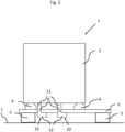
- Fig. 2 shows an alternative embodiment wherein the heat pump 1 comprises two openings 6 each configured to receive a securing member 10.
- the securing members 10 shown in Fig. 2 differ in the shape of their handling end 12 from the securing members 10 shown in fig. 1 .
- the securing member 10 can be a butterfly screw which can be easier removed than the securing member 10 shown in fig. 1 , as such securing members in Fig. 2 do not require any tool to be removed.
- Fig. 3 shows an embodiment wherein the opening 6 is provided in a side panel of the housing 3.
- the vibration pads 4 are arranged on another panel, in particular bottom panel, of the housing 3, in particular a panel that is directly connected with the side panel of the housing 3.
- Said embodiment is advantageous when the heat pump is transported lying down. With “lying down” it is meant a position of the heat pump 1 that is rotated 90° in clockwise direction than the position shown in fig. 3 .
- the securing member 10 supports the compressor 2 to avoid a high torque on the non-shown fixing elements fixing the anti-vibration pads 4 to the housing 3.
- openings 6 may be provided in one or more side panels and/or bottom panel, and that each panel may have one or more openings 6.
- Fig.4 schematically shows a heat pump according to an alternative embodiment.
- Said embodiment differs from the embodiments shown in fig. 1-3 in that the embodiment comprises two stages of anti-vibration pads 4. Thereto, it is possible to efficiently decouple the vibrations and to reduce the noise generated by the compressor 2.
- the compressor 2 rests on a compressor support plate 14.
- Anti-vibration pads 4 are positioned between the compressor 2 and the support plate 14. One end of the anti-vibration pad 4 is in contact with the compressor 2. The other end is in contact with the support plate 14.
- a fastener element 15 shown in fig. 6 is used to fix the compressor 2 to the anti-vibration pad 4 and to fix the anti-vibration pad 4 to the support plate 14.
- the housing 3 supports the support plate 14 via further anti-vibration pads 4.
- Said further anti-vibration pads 4 are arranged between the housing 3 and the support plate 14.
- the support pate 14 is arranged between the housing 3 and the compressor.
- One end of said further anti-vibration pad 4 is in contact with the support plate 14.
- the other end of said further anti-vibration pad 4 is in contact with the housing.
- a further fastener element 15 is used to fix the further anti-vibration pad 4 to the housing 3.
- the anti-vibration pads act as shock absorbers.
- a further difference to the embodiment shown in fig. 1-3 is that an intermediate element, in particular a crimped nut 16, is provided wherein the nut 16 is fixedly connected to the support plate 14.
- the housing 3, in particular bottom panel, comprises the opening 6.
- the securing member 10 passes through the opening 6 and is fixed in the thread of the crimped nut 16.
- the contact end portion 11 of the securing member 10 is fixed to the crimped nut 16.
- the securing member 10 mechanically locks the support plate 14 with the housing 3.
- the damping action of the anti-vibration pads 4 between the support plate 14 and the housing 3 is eliminated.
- the action of the anti-vibration pads 4 on the top is not modified and they damp movements of the compressor 2.
- said embodiment enables to reduce the oscillations of the compressor 2 during the transport.
- Fig. 5 schematically depicts a heat pump 1 according to the embodiment shown in fig. 4 in more detail.
- fig. 5 shows details of the refrigerant circulation circuit comprising the compressor 2.
- a single support 5 is provided that runs along substantially the entire bottom panel.
- Fig. 6 shows a more detailed view of part of the heat pump 1 shown in Fig. 5 .
- Fig. 6 shows a fixing means 15 by means of which the compressor 2 is fixed to the anti-vibration pad 4 and by means of this the anti-vibration pad 4 is fixed to the support plate 14. Additionally, further fixing means 15 are shown by means of which the further anti-vibration pads 4 are fixed to the housing 3, in particular to the bottom panel.
Landscapes
- Engineering & Computer Science (AREA)
- Mechanical Engineering (AREA)
- General Engineering & Computer Science (AREA)
- Chemical & Material Sciences (AREA)
- Combustion & Propulsion (AREA)
- Compressor (AREA)
Abstract
The invention relates to a heat pump (1) comprising a housing (3) and a compressor (2). The compressor (2) being positioned on one or more anti-vibration pads (4) in an inner space of the housing (3), wherein the housing (3) comprises an opening (6) configured to receive a securing member (10), which when inserted from an outside of the housing (3) through the opening (6) is in direct or indirect contact with the compressor (2) to, in particular rigidly, secure the compressor (2) with respect to the housing (3), said securing member (10) is removable from the outside of the housing (3) .
Description
- The invention relates to a heat pump and a method of securing a heat pump.
- Heat pumps typically comprise a compressor. Compressors used in heat pumps are sensitive components, in particular as compressors comprise moving parts. The moving parts are used to compress fluids, so need to be carefully dimensioned and positioned. To limit friction and improve the service life of the compressor, oil is used as lubricant.
- The compressor has at least one motor that rotates one of the elements that allow the compressor to work. The entire compressor environment is pressurized. The heat pump is a heavy, bulky and vulnerable object, making its transportation risky.
- During all transport phases from the place of manufacture to the place of installation, the heat pump is subjected to external events, such as accelerations, shocks, tilting, vibrations etc. Each time the heat pump is subjected to such an external event, this may impact and weaken the compressor within the heat pump, reducing its quality and life span. A further problem is that when there is a positive or negative acceleration of the heat pump the compressor can initiate a movement due to its fixing on anti-vibrating pads and due the degree of relative freedom of movement offered by this type of solution. This creates a high inertia of the compressor and thus creates more energy and stress on the fixing elements by means of which the anti-vibration pads are fixed on the housing of the heat pump, or on the support plate or on the heat pump panels. As a result, the compressor mounting parts can also be damaged, leading to reliability problems for the heat pump. Some of these external events are, for example, described and tested in the standards associated with transport, such as the following normative texts ASTM D880-92, ASTM D999, ASTM D4728, ASTM D642, ASTM D6055-96 / D880-92 / D6179-07.
- The heat pump may be placed on flexible anti-vibration pads. The purpose of these pads is to reduce the transmission of vibrations from the compressor to the rest of the heat pump when the heat pump is installed and the compressor is running. It enables to reduce the noise generated by the heat pump due to the vibration of the compressor. However, during the transport phase, this type of pads accentuates the shocks that the compressor and its fastening elements undergoes because it provides the compressor with more freedom of movement and inertia before a sudden stop.
- A damage in the compressor area can occur during the transport of the heat pump. In particular, one or more anti-vibration pads can bent or be broken resulting in that the compressor is not arranged horizontally during the heat pump operation. The compressor cannot be reattached horizontally as these structural parts are not replaceable. When the compressor is no longer arranged horizontally, it can no longer operate efficiently and reliably.
- Furthermore, if the compressor has moved, it also means that the tubing of the associated refrigeration circuit has been deformed and is therefore at risk of leaking or a premature end of life. In the case of flammable refrigerant, this means that a damage of the support of the compressor can cause flammable fluid, in particular propane, to leak out of the compressor and thus pose a risk of product explosion.
- In order to limit the impact of the anti-vibration pads under the compressors during the transport phases, several solutions exist to fixate or stabilize the compressor for transport that needs to be removed when the product will be installed and before initial operation. For example, this may be done with the use of shims or flexible studs between the compressor and its support integrated before the transport. Another solution is to install additional screws or to securely fix the compressor for transport.
- These known solutions require access to the compressor and the space around the compressor inside the heat pump after the transport in order to remove them, which is cumbersome and risky. As the compressor contains and is connected to elements where refrigerant circulates. The refrigerant may be under pressure, is potentially toxic, flammable or causing burns due to its temperature of use. Moreover, other elements such as probes, electrical connections and various components are present, which require careful handling. Thus, providing access to the area around the compressor to remove solutions fixing the compressor used for the transport should therefore be kept to a minimum, as the slightest mistake can lead to problems with the operation of the heat pump or its service life. Thus, installing or removing components in this area to release the compressor and allow it to rest on the anti-vibration mounts poses a risk to the entire heat pump. This risk increases when heat pumps with flammable refrigerants, in particular propane, are used.
- Also, for these reasons, heat pumps are more and more designed to limit or prevent such access, so the known solutions cannot be used or if used, it may generate some risks when removing these solutions to install the heat pump.
- The object of the invention is therefore to provide an alternative way to limit damage to the compressor or its fastening elements as a result of external events, such as accelerations, shocks, tilting, vibrations, that could occur during transportation while allowing the use of anti-vibration pads when the compressor is running.
- The object is solved by a heat pump comprising a housing and a compressor, the compressor being positioned on one or more anti-vibration pads in an inner space of the housing, wherein the housing comprises an opening configured to receive a securing member, which when inserted from an outside of the housing through the opening is in direct or indirect contact with the compressor to, in particular rigidly, secure the compressor with respect to the housing, said securing member is removable from the outside of the housing .
- "Rigidly securing" means that the securing member is configured to prevent a movement of the compressor relative to the housing, in particular the panel through which the securing member passes. Thus, the "rigid securing" ensures that the compressor remains its position or basically remains in its position within the inner space of the housing during heat pump transport.
- Without the securing member used for rigidly securing the compressor to the housing, the compressor can move freely by about 2 to 10 mm, mostly in a horizontal plane. This results, due to the vibration of the compressor which imposes a horizontal force with the motor. It can also move vertically by a few millimetres if a force is imposed on the top, but it is not supposed to experience any force in this axis. Once the securing member is in place, the possible degree of freedom of the compressor under standard loads (e.g. 50N point) is less than 1 mm resulting from tolerances of the components and mechanical rigidity of concerned parts.
- The securing member, once inserted, secures the compressor by preventing movement of the compressor with respect to the housing. The securing member is rigid to secure the compressor in place. The securing member may have any suitable shape and may be formed as a securing rod (substantially cylindrically shaped). The opening in the housing to receive a securing member may also be referred to as a securing member receiving opening. The securing member may be in direct contact with the compressor, for instance by abutting the outside of the compressor. The securing member may also be in indirect contact with the compressor, for instance by abutting an intermediate member positioned in between the securing member and the outside of the compressor. The intermediate member can be a crimped nut as it is explained below more in detail. For the case that an intermediate member is provided, the intermediate member can be in direct contact with the compressor.
- The securing member may be in contact with a point of the compressor or with a surface area of the compressor. Alternatively, the securing member may be in contact with a point of the intermediate member or with a surface area of the intermediate member.
- There is provided a heat pump with means to fasten the compressor which can be inserted and removed from the outside of the heat pump, without accessing the area integrating the heat pump components. Thereto, the securing member is configured such that it can be removed from the outside without accessing the inner space of the housing. This can be achieved in that a part, in particular a handling end of the securing member, protrude from the housing in a direction away from the inner space of the housing. There is therefore no risk of damaging the refrigerant circuit or other elements such as probes, electrical connections and various other components. The risk of leaks, safety hazards, and malfunctions that can reduce the performance or life of the product is thus reduced.
- "Removable from the outside" means that the securing member can be removed from a region outside the heat pump without the need to get access to the interior of the heat pump. Thus, there is no need to open the heat pump housing to remove the securing member.
- This solution makes it possible to install the entire heat pump without a need to access the technical inner space of the heat pump, when at least one securing member to secure the compressor is used during the transport. Said at least one securing member needs to be removed at the installation before initial operation. In fact, for a monobloc heat pump, the minimum connections to be made are the hydraulic and electrical connections (power and sensor). These connections can be made from outside the heat pump if the design allows. This allows the installer to avoid opening the heat pump housing and thus avoid any associated risk of damaging the product. As installation is made easier, less skill and qualifications, in particular with respect working with refrigerants, are required from the person installing the heat pump.
- Once the securing members are placed, the compressor is held in place during transport and prevents it from moving or shifting too much. The compressor and the attached circuit are not subject to too much displacement and shocks so displacements on the heat pump and in particular on the refrigerant circuit are limited. The securing member prevents the compressor from moving with respect to the housing, which movement would otherwise be facilitated by the anti-vibration pads. Movement of the compressor during transport on the anti-vibration pads may result in damage to the compressor or the associated refrigerant circuit as such movements are amplified due to softness features from the anti-vibration pads Thus the securing member ensures the reliability of the compressor and its service life.
- According to an embodiment the heat pump comprises the securing member fixed to the housing and extending through the opening, the securing member having a contact end portion in direct or indirect contact with the compressor to secure the compressor with respect to the housing and the securing member having a handling end extending on an outside of the housing configured to insert and retract the securing member in and out of the opening. The handling hand can be a fitting for a tool, in particular for a screwdriver, spanner or other tools. Securing member can be a screw with a handling hand, in particular with the aforementioned fitting for a tool.
- The opening is adjacent the compressor such that the securing member, when inserted through the opening, can reach the compressor. The securing member may be fixed to the housing of the heat pump.
- The securing member may be installed by sliding or inserting the securing member into the opening in the housing until the contact end portion of the securing member contacts the compressor, or indirectly contacts the compressor. The contact point on the compressor is preferably at the bottom of the compressor. The securing member is then fixed to the housing to hold the securing member in position to that the support on the compressor is constant, robust and long-lasting.
- The securing member can indirectly contact the compressor via an intermediate member of the heat pump. The heat pump can comprise a support plate that is arranged between the compressor and the housing. The intermediate member can be fixedly connected to the support plate wherein the intermediate element receives a part of the securing element and/or is in direct contact with the compressor. "Fixedly connected" means that the intermediate member and the support plate cannot move relative to each other. The intermediate member can be any member that comprises a fixing means for fixing the securing member, in particular the contact end portion of the securing member. For example, the intermediate member can be nut or a pin or a screwed assembly.
- The compressor can be supported by the support plate by means of at least one anti-vibration pad and/or that the support plate can be supported by the housing by means of at least one anti-vibration pad. The support plate can support only the compressor or can in addition support other elements of the heat pump such as heat exchanger or pipings. Three anti vibration pads can be arranged between the compressor and support plate and four additional anti vibration pads can be arranged between support plate and the housing.
- According to an embodiment the heat pump further comprising fixing means configured to fix the securing member in position when inserted through the opening.
- According to an embodiment the fixing means are provided by a screw thread on at least part of an outer surface of the securing member, which engages with the opening to fix the securing member in position.
- The securing member may comprise a mid-section having a cylindrical shape the mid-section being in between the contact end portion and the handling end, and the mid-section comprising a screw thread on the outer circumference of the mid-section. The opening may comprise a matching screw thread on an inner circumference of the opening configured to receive the screw thread of the securing member.
- The securing member can easily be inserted and fixed by screwing the securing member into the opening until it is in position.
- According to an embodiment the handling end comprises a handle configured to allow manually screwing the securing member into the opening. The handle may be a knob that is configured to be handled by a human hand.
- According to an embodiment the securing member has a body axis which extends from the contact end portion to the handling end and the securing member comprises a fixing opening which extends through the securing member in a direction perpendicular to the body axis, and wherein the fixing means are provided by a pin which is inserted through the fixing opening and which is flush with the housing.
- The securing member may advantageously be fixed to the heat pump by introducing a pin in the securing member. The pin is held in position and the support on the compressor is constant, robust and long-lasting. This provides for removable fixing means that are easy to install and remove.
- According to an embodiment the compressor comprises a contact section configured to receive the contact end portion of the securing member. Likewise, the intermediate member comprises a contact section configured to receive the contact end portion of the securing member.
- To prevent damage to the compressor caused by the securing member, the compressor may be configured to receive the contact end portion of the securing member, for instance by comprising a receiving pad made of a durable material.
- According to an embodiment the contact section of the compressor comprises contact opening to receive the contact end portion of the securing member. In this embodiment the contact end portion of the securing member, once introduced in the opening, limits relative movement of the compressor in several directions, i.e. also perpendicular to the body axis of the securing member.
- According to an embodiment the contact opening comprises a screw thread on an inner surface of the contact opening and the contact end portion of the securing member comprises a screw thread on its outer surface.
- The screw thread on the inner surface of the contact opening and the screw thread on the outer surface of the contact end portion are matching and configured to engage. This is an alternative way of providing the fixing means.
- This is an advantageous embodiment as the contact end portion of the securing member, once introduced in the opening, limits relative movement of the compressor in several directions, i.e. perpendicular to the body axis of the securing member as well as in a direction along the body axis in two directions.
- According to an embodiment the heat pump comprises two or more openings each configured to receive a securing member, which when inserted from an outside of the housing through the respective opening is in direct or indirect contact with the compressor to secure the compressor with respect to the housing.
- This provides for increased stability and fixation of the compressor. Also, forces caused by external events may be absorbed at two or more locations, reducing the impact on the individual securing members and the heat pump.
- According to an embodiment
- the housing comprises a bottom panel and the bottom panel comprises one or more openings configured to receive a securing member and/or
- the housing comprises a side panel and the side panel comprises one or more openings configured to receive a securing member and/or
- the housing comprises a first side panel a second side panel, the first side panel comprises one or more openings configured to receive a securing member and the second side panel comprises one or more openings configured to receive a securing member.
- Providing an opening configured to receive a securing member in the bottom panel has the advantage that shocks in a direction perpendicular to the bottom panel are most effectually absorbed. Providing an opening configured to receive a securing member in a side panel has the advantage that shocks in a direction perpendicular to the side panel are most effectually absorbed. Providing an opening in a first side panel and an opening in a second side panel provides an even more robust securing of the compressor. The first and second side panel may be at an angle with respect to each other, e.g. 90 degrees, securing the compressor in different angles. Each panel (bottom, side, first, second) may comprise one or more openings configured to receive a securing member.
- As already discussed above the compressor can be fixed with fastener elements to the support plate. The fastener elements can be surrounded by flexible material dampers, i.e. the anti-vibration pads. The fastener elements can comprise nuts and screws, respectively, wherein the nuts on the screws are not tightened very much. This allows the compressor to be held in relation to its support plate but still be damped by the anti-vibration pads. This gives the compressor enough freedom of movement when operating for vertical and horizontal oscillations in the range of 2 to 10 mm.
- To prevent the compressor from gaining inertia during transport, it is advisable to limit horizontal and vertical oscillations by means of the securing members. Thereto, it is necessary to provide securing members for rigidly securing the compressor in vertical or horizontal direction. However, such a solution requires at least one point support on the vertical axis and two point supports on the horizontal at perpendicular directions. If there is only one possible point for the support member, it is more relevant to position the compressor vertically because it has a higher influence as the two horizontal blocking points.
- However, if the heat pump product shall be transported lying down, it is recommendable to provide a blocking point for the support member on a side panel so that the compressor rests on it during the transport lied down.
- The compressor can be placed on the housing, in particular a bottom panel, wherein several anti-vibration pads can be positioned between the compressor and housing. In particular, three anti-vibration pads can be positioned between the compressor and housing.
- According to an aspect there is provided a securing member configured to be inserted and retracted in and out of an opening of a heat pump as provided above.
- According to a further aspect there is provided a method of securing a heat pump, the heat pump comprising a housing and a compressor, the compressor being positioned on one or more anti-vibration pads in an inner space of the housing, wherein the housing comprises an opening configured to receive a securing member, which when inserted from an outside of the housing through the opening is in direct or indirect contact with the compressor to secure the compressor with respect to the housing, the method comprising inserting a securing member from an outside of the housing through the opening, and positioning a contact end portion of the securing member to be in direct or indirect contact with the compressor to secure the compressor with respect to the housing. Additionally, the method can comprise fixing the securing member in position.
- According to an embodiment the method further comprises transporting the heat pump to an installation site.
- According to an embodiment the method further comprises releasing the securing member and retract the securing member from the opening after transporting the heat pump to an installation site.
- In the figures, the subject-matter of the invention is schematically shown, wherein identical or similarly acting elements are usually provided with the same reference signs.
- Figure 1
- schematically shows a heat pump according to an embodiment,
- Figure 2
- schematically shows a heat pump according to an alternative embodiment,
- Figure 3
- schematically shows a heat pump according to an alternative embodiment,
- Figure 4
- schematically shows a heat pump according to an alternative embodiment,
- Figure 5
- schematically shows the internals of a heat pump in more detail according to the embodiment of
Figure 4 , and - Figure 6
- schematically shows a more detailed view of part of
Figure 5 . -
Figure 1 shows aheat pump 1 having ahousing 3. Thehousing 3 may be formed by a plurality of panels, side panels, bottom panel, top panel, forming an inner. Only a bottom panel is shown inFig. 1 . - The
heat pump 1 may comprise a refrigerant circulation circuit comprising a condenser, an expansion valve, an evaporator and acompressor 2 fluidly connected by refrigerant piping to form a heat exchange circuit. Of these elements,Fig. 1 only thecompressor 2 is schematically shown. - The
compressor 2 is placed on a plurality ofanti-vibration pads 4 inside thehousing 3.Fig. 1 shows twoanti-vibration pads 4, but any number of may be applied, such as three or fouranti-vibration pads 4. Theanti-vibration pads 4 may rest on a bottom panel of thehousing 3. The anti-vibration pads limit vibration caused by a working compressor to be transferred to the rest of theheat pump 1. However, during transport, theanti-vibration pads 4 provide thecompressor 2 with a freedom of movement which may harm thecompressor 2 or its fastener elements or supporting parts. - The non-shown fastener element is used to fix the
anti-vibration pads 4 to thehousing 3. Additionally, the fastener element is used to fix thecompressor 2 to theanti-vibration pads 4. Thus, the fastener element ensures that thecompressor 2 is fixed to thehousing 3 via theanti-vibration pads 4 and that the compressor cannot move relative to theanti-vibration pads 4. The fastener element can be arranged in theanti-vibration pads 4 that the fastener element fixes to thehousing 3. - The
housing 3 comprises anopening 6, which may also be referred to as a securingmember receiving opening 6, configured to receive a securingmember 10, which when inserted from an outside of thehousing 3 through theopening 6, is in direct or indirect contact with thecompressor 2 to secure thecompressor 2 with respect to thehousing 3. The securingmember 10 secures thecompressor 2 by limiting movement of thecompressor 2 with respect to thehousing 3. The securingmember 10 as depicted inFig. 1 may also be referred to as a securing rod. - The
heat pump 1 is positioned onsupports 5 to raise thehousing 3 above the ground orfloor 7. Thesesupports 5 create space for a user to insert and retract the securingmember 10 in and out of theopening 6. - The securing
member 10 has acontact end portion 11 which is inserted through theopening 6 until it is in contact with thecompressor 2. The securing member has a handlingend 12 which allows a user to hold and handle the securingmember 10 during insertion, fixing, unfixing and retracting the securingmember 10. The handlingend 12 protrudes from thehousing 3 and thus is accessible from the outside of thehousing 3. - The securing
member 10 is fixed to thehousing 3 by fixing means.Fig. 1 shows a securingmember 10 that is a screw with a male thread. Thehousing 3 includes a female thread that is engaged with the securingmember 10. Awasher 13 is provided to increase the bearing surface of the screw and therefore the stability of the assembly. -
Fig. 2 shows an alternative embodiment wherein theheat pump 1 comprises twoopenings 6 each configured to receive a securingmember 10. Of course, more than twoopenings 6 may be provided. The securingmembers 10 shown inFig. 2 differ in the shape of their handlingend 12 from the securingmembers 10 shown infig. 1 . In particular, the securingmember 10 can be a butterfly screw which can be easier removed than the securingmember 10 shown infig. 1 , as such securing members inFig. 2 do not require any tool to be removed. -
Fig. 3 shows an embodiment wherein theopening 6 is provided in a side panel of thehousing 3. Such an embodiment facilitates easy installation and removal of the securingmember 10. Thevibration pads 4 are arranged on another panel, in particular bottom panel, of thehousing 3, in particular a panel that is directly connected with the side panel of thehousing 3. Said embodiment is advantageous when the heat pump is transported lying down. With "lying down" it is meant a position of theheat pump 1 that is rotated 90° in clockwise direction than the position shown infig. 3 . In said case the securingmember 10 supports thecompressor 2 to avoid a high torque on the non-shown fixing elements fixing theanti-vibration pads 4 to thehousing 3. - It will be understood that
openings 6 may be provided in one or more side panels and/or bottom panel, and that each panel may have one ormore openings 6. -
Fig.4 schematically shows a heat pump according to an alternative embodiment. Said embodiment differs from the embodiments shown infig. 1-3 in that the embodiment comprises two stages ofanti-vibration pads 4. Thereto, it is possible to efficiently decouple the vibrations and to reduce the noise generated by thecompressor 2. - To achieve this, the
compressor 2 rests on acompressor support plate 14.Anti-vibration pads 4 are positioned between thecompressor 2 and thesupport plate 14. One end of theanti-vibration pad 4 is in contact with thecompressor 2. The other end is in contact with thesupport plate 14. Afastener element 15 shown infig. 6 is used to fix thecompressor 2 to theanti-vibration pad 4 and to fix theanti-vibration pad 4 to thesupport plate 14. - The
housing 3 supports thesupport plate 14 viafurther anti-vibration pads 4. Said furtheranti-vibration pads 4 are arranged between thehousing 3 and thesupport plate 14. Thus, thesupport pate 14 is arranged between thehousing 3 and the compressor. One end of saidfurther anti-vibration pad 4 is in contact with thesupport plate 14. The other end of saidfurther anti-vibration pad 4 is in contact with the housing. Afurther fastener element 15 is used to fix thefurther anti-vibration pad 4 to thehousing 3. As is discussed above the anti-vibration pads act as shock absorbers. - A further difference to the embodiment shown in
fig. 1-3 is that an intermediate element, in particular a crimpednut 16, is provided wherein thenut 16 is fixedly connected to thesupport plate 14. Thehousing 3, in particular bottom panel, comprises theopening 6. The securingmember 10 passes through theopening 6 and is fixed in the thread of the crimpednut 16. In particular, thecontact end portion 11 of the securingmember 10 is fixed to the crimpednut 16. - The securing
member 10 mechanically locks thesupport plate 14 with thehousing 3. Thus, the damping action of theanti-vibration pads 4 between thesupport plate 14 and thehousing 3 is eliminated. The action of theanti-vibration pads 4 on the top is not modified and they damp movements of thecompressor 2. However, said embodiment enables to reduce the oscillations of thecompressor 2 during the transport. -
Fig. 5 schematically depicts aheat pump 1 according to the embodiment shown infig. 4 in more detail. In particularfig. 5 shows details of the refrigerant circulation circuit comprising thecompressor 2. According to this embodiment, asingle support 5 is provided that runs along substantially the entire bottom panel.Fig. 6 shows a more detailed view of part of theheat pump 1 shown inFig. 5 . -
Fig. 6 shows a fixing means 15 by means of which thecompressor 2 is fixed to theanti-vibration pad 4 and by means of this theanti-vibration pad 4 is fixed to thesupport plate 14. Additionally, further fixing means 15 are shown by means of which thefurther anti-vibration pads 4 are fixed to thehousing 3, in particular to the bottom panel. -
- 1.
- Heat pump
- 2.
- Compressor
- 3.
- Housing
- 4.
- Anti-vibration pads
- 5.
- Heat pump support
- 6.
- Securing member receiving opening
- 7.
- Ground/floor
- 10.
- Securing member
- 11.
- Contact end portion
- 12.
- Handling end
- 13.
- Washer
- 14.
- Support plate
- 15.
- Fastener element
- 16.
- Nut
Claims (15)
- Heat pump (1) comprising a housing (3) and a compressor (2), the compressor (2) being positioned on one or more anti-vibration pads (4) in an inner space of the housing (3), wherein the housing (3) comprises an opening (6) configured to receive a securing member (10), which when inserted from an outside of the housing (3) through the opening (6) is in direct or indirect contact with the compressor (2) to, in particular rigidly, secure the compressor (2) with respect to the housing (3), said securing member (10) is removable from the outside of the housing (3).
- Heat pump (1) according to claim 1, the heat pump (1) comprises the securing member (10) fixed to the housing (3) and extending through the opening (6), the securing member (10) having a contact end portion (11) in direct or indirect contact with the compressor (2) to secure the compressor (2) with respect to the housing (3) and the securing member (10) having a handling end (12) extending on an outside of the housing (3) configured to insert and retract the securing member (10) in and out of the opening (6).
- Heat pump (1) according to any one of the preceding claims, the heat pump (1) comprises a flammable refrigerant and/or the heat pump (1) further comprising fixing means configured to fix the securing member (10) in position when inserted through the opening (6).
- Heat pump (1) according to claim 3, wherein the fixing means is provided by a screw thread on at least part of an outer surface of the securing member (10), which engages with the opening (6) to fix the securing member in position.
- Heat pump (1) according to claim 3, wherein the securing member (10) has a body axis which extends from the contact end portion (11) to the handling end (12) and the securing member (10) comprises a fixing opening which extends through the securing member in a direction perpendicular to the body axis, and wherein the fixing means are provided by a pin which is inserted through the fixing opening, in particular and which is flush with the housing (3).
- Heat pump according to at least one of the claims 1 to 5, characterized in that the heat pump comprises a support plate (14) that is arranged between the compressor and the housing (3).
- Heat pump according to claim 6, characterized in that an intermediate member, in particular nut, is fixedly connected to the support plate (14) wherein the intermediate element receives a part of the securing element (11) and/or is in direct contact with the compressor.
- Heat pump according to claim 6 or 7, characterized in that the compressor (2) is supported by the support plate (14) by means of at least one anti-vibration pad (4) and/or that the support plate (14) is supported by the housing (3) by means of at least one anti-vibration pad (4).
- Heat pump (1) according to any one of the preceding claims, wherein the compressor (2) or the intermediate member comprises a contact section configured to receive the contact end portion (11) of the securing member (10).
- Heat pump (1) according to any one of the preceding claims, wherein the heat pump (1) comprises two or more openings (6) each configured to receive a securing member (10), which when inserted from an outside of the housing (3) through the respective opening (6) is in direct or indirect contact with the compressor (2) to secure the compressor (2) with respect to the housing (3).
- Heat pump (1) according to any one of the preceding claims, wherein- the housing (3) comprises a bottom panel and the bottom panel comprises one or more openings configured to receive a securing member (10) and/or- the housing (3) comprises a side panel and the side panel comprises one or more openings configured to receive a securing member (10) and/or- the housing (3) comprises a first side panel a second side panel, the first side panel comprises one or more openings configured to receive a securing member (10) and the second side panel comprises one or more openings configured to receive a securing member (10).
- Method of securing a heat pump (1), the heat pump (1) comprising a housing (3) and a compressor (2), the compressor (2) being positioned on one or more anti-vibration pads (4) in an inner space of the housing (3), wherein the housing (3) comprises an opening configured to receive a securing member (10), which when inserted from an outside of the housing (3) through the opening is in direct or indirect contact with the compressor (2) to, in particular rigidly, secure the compressor (2) with respect to the housing (3), the method comprising:- inserting a securing member (10) from an outside of the housing (3) through the opening (6),- positioning a contact end portion (11) of the securing member (10) to be in direct or indirect contact with the compressor (2) to secure the compressor (2) with respect to the housing (3).
- Method according to claim 12, wherein the method further comprises fixing the securing member (10) in position.
- Method according to claim 12 or 13, wherein the method further comprises transporting the heat pump (1) to an installation site.
- Method according to any one of the claims 12 - 14, wherein the method further comprises releasing the securing member (10) and retract the securing member (10) from the opening.
Priority Applications (1)
| Application Number | Priority Date | Filing Date | Title |
|---|---|---|---|
| EP23181112.6A EP4481198A1 (en) | 2023-06-23 | 2023-06-23 | Heat pump and method of securing a heat pump for transport |
Applications Claiming Priority (1)
| Application Number | Priority Date | Filing Date | Title |
|---|---|---|---|
| EP23181112.6A EP4481198A1 (en) | 2023-06-23 | 2023-06-23 | Heat pump and method of securing a heat pump for transport |
Publications (1)
| Publication Number | Publication Date |
|---|---|
| EP4481198A1 true EP4481198A1 (en) | 2024-12-25 |
Family
ID=87047810
Family Applications (1)
| Application Number | Title | Priority Date | Filing Date |
|---|---|---|---|
| EP23181112.6A Pending EP4481198A1 (en) | 2023-06-23 | 2023-06-23 | Heat pump and method of securing a heat pump for transport |
Country Status (1)
| Country | Link |
|---|---|
| EP (1) | EP4481198A1 (en) |
Cited By (1)
| Publication number | Priority date | Publication date | Assignee | Title |
|---|---|---|---|---|
| DE102024127323A1 (en) * | 2024-09-23 | 2026-03-26 | Vaillant Gmbh | Transport securing device for a heat pump |
Citations (7)
| Publication number | Priority date | Publication date | Assignee | Title |
|---|---|---|---|---|
| US5306121A (en) * | 1993-04-23 | 1994-04-26 | Carrier Corporation | Compressor tiered mounting arrangement |
| US6260373B1 (en) * | 2000-02-16 | 2001-07-17 | American Standard International Inc. | Heat exchanger with double vibration isolation |
| US20050073118A1 (en) * | 2003-10-07 | 2005-04-07 | Midwest Air Technologies, Inc. | Dolly for portable air compressor |
| EP3789696A1 (en) * | 2018-05-01 | 2021-03-10 | Mitsubishi Electric Corporation | Geothermal heat pump system |
| CN113417922A (en) * | 2021-07-26 | 2021-09-21 | 珠海格力电器股份有限公司 | Positioning bolt and vibration reduction positioning structure of compressor |
| CN216048110U (en) * | 2021-06-03 | 2022-03-15 | 徐啸 | Multi-cold-heat source shared energy-saving heating and ventilation system |
| EP3825158B1 (en) * | 2018-09-21 | 2023-01-11 | Mitsubishi Heavy Industries Thermal Systems, Ltd. | Refrigeration unit for transportation, and method of assembling refrigeration unit for transportation |
-
2023
- 2023-06-23 EP EP23181112.6A patent/EP4481198A1/en active Pending
Patent Citations (7)
| Publication number | Priority date | Publication date | Assignee | Title |
|---|---|---|---|---|
| US5306121A (en) * | 1993-04-23 | 1994-04-26 | Carrier Corporation | Compressor tiered mounting arrangement |
| US6260373B1 (en) * | 2000-02-16 | 2001-07-17 | American Standard International Inc. | Heat exchanger with double vibration isolation |
| US20050073118A1 (en) * | 2003-10-07 | 2005-04-07 | Midwest Air Technologies, Inc. | Dolly for portable air compressor |
| EP3789696A1 (en) * | 2018-05-01 | 2021-03-10 | Mitsubishi Electric Corporation | Geothermal heat pump system |
| EP3825158B1 (en) * | 2018-09-21 | 2023-01-11 | Mitsubishi Heavy Industries Thermal Systems, Ltd. | Refrigeration unit for transportation, and method of assembling refrigeration unit for transportation |
| CN216048110U (en) * | 2021-06-03 | 2022-03-15 | 徐啸 | Multi-cold-heat source shared energy-saving heating and ventilation system |
| CN113417922A (en) * | 2021-07-26 | 2021-09-21 | 珠海格力电器股份有限公司 | Positioning bolt and vibration reduction positioning structure of compressor |
Cited By (1)
| Publication number | Priority date | Publication date | Assignee | Title |
|---|---|---|---|---|
| DE102024127323A1 (en) * | 2024-09-23 | 2026-03-26 | Vaillant Gmbh | Transport securing device for a heat pump |
Similar Documents
| Publication | Publication Date | Title |
|---|---|---|
| EP2774251B1 (en) | Generator set mount | |
| CN107002507B (en) | Multipoint Mounting System for Rotating Machinery | |
| JP6219763B2 (en) | Compressor washer fixing jig and compressor fixing method | |
| US11879264B2 (en) | Dual-phase vibration damping building coupling member with lock-up | |
| US10368459B2 (en) | Equipment clamping assembly using clamps and friction to secure equipment for use in rugged and other environments | |
| JP5873991B2 (en) | Compressor fixing structure | |
| US7918432B2 (en) | Conical washer spring support | |
| CN110088468B (en) | Passive actuator for suppressing vibration of cylindrical casing of vertical pump, vertical pump and method of improving vertical pump | |
| EP3336406B1 (en) | Mounting system for rotating machinery | |
| US11566647B2 (en) | Acousto-optic device with captive fastener and related assemblies and methods | |
| JP6567062B2 (en) | Air conditioner outdoor unit | |
| US20190368788A1 (en) | Noise preventing/reducing structure and method for a refrigerator | |
| CN217736153U (en) | Vibration isolation unlocking device for sky patrol module | |
| JP2024178888A5 (en) | ||
| US6209927B1 (en) | Isolation device and fluid connection | |
| WO2019241494A1 (en) | Vibration isolation system with thermal growth compensation | |
| JP2024178888A (en) | Pump stand for vacuum pumps | |
| US6022178A (en) | Flexure washer bearing and method | |
| CN112673151B (en) | Machine room and steam turbine | |
| JPS58152184A (en) | Vibration reducing apparatus for compressor | |
| KR102291124B1 (en) | Vibration Isolation Apparatus for Launching Vehicle Having Shape Memory Damper | |
| EP1467121A2 (en) | Shock attenuating mounting bracket | |
| JP2016118214A (en) | Vibration control device and refrigeration cycle device using the same | |
| KR102291129B1 (en) | Vibration Isolation Apparatus for Launching Vehicle Having Elastic Damper | |
| JPS62274183A (en) | pipe supports |
Legal Events
| Date | Code | Title | Description |
|---|---|---|---|
| PUAI | Public reference made under article 153(3) epc to a published international application that has entered the european phase |
Free format text: ORIGINAL CODE: 0009012 |
|
| STAA | Information on the status of an ep patent application or granted ep patent |
Free format text: STATUS: THE APPLICATION HAS BEEN PUBLISHED |
|
| AK | Designated contracting states |
Kind code of ref document: A1 Designated state(s): AL AT BE BG CH CY CZ DE DK EE ES FI FR GB GR HR HU IE IS IT LI LT LU LV MC ME MK MT NL NO PL PT RO RS SE SI SK SM TR |
|
| STAA | Information on the status of an ep patent application or granted ep patent |
Free format text: STATUS: REQUEST FOR EXAMINATION WAS MADE |
|
| 17P | Request for examination filed |
Effective date: 20250617 |