EP3789696A1 - Geothermal heat pump system - Google Patents
Geothermal heat pump system Download PDFInfo
- Publication number
- EP3789696A1 EP3789696A1 EP18917378.4A EP18917378A EP3789696A1 EP 3789696 A1 EP3789696 A1 EP 3789696A1 EP 18917378 A EP18917378 A EP 18917378A EP 3789696 A1 EP3789696 A1 EP 3789696A1
- Authority
- EP
- European Patent Office
- Prior art keywords
- heat exchanger
- compressor
- vibration isolation
- primary
- pump system
- Prior art date
- Legal status (The legal status is an assumption and is not a legal conclusion. Google has not performed a legal analysis and makes no representation as to the accuracy of the status listed.)
- Pending
Links
- 239000003507 refrigerant Substances 0.000 claims abstract description 51
- 239000007788 liquid Substances 0.000 claims abstract description 13
- 238000002955 isolation Methods 0.000 claims description 99
- 239000006096 absorbing agent Substances 0.000 claims description 17
- 239000000463 material Substances 0.000 abstract description 8
- XLYOFNOQVPJJNP-UHFFFAOYSA-N water Substances O XLYOFNOQVPJJNP-UHFFFAOYSA-N 0.000 description 86
- 238000010438 heat treatment Methods 0.000 description 22
- 239000012267 brine Substances 0.000 description 17
- HPALAKNZSZLMCH-UHFFFAOYSA-M sodium;chloride;hydrate Chemical compound O.[Na+].[Cl-] HPALAKNZSZLMCH-UHFFFAOYSA-M 0.000 description 17
- 238000004378 air conditioning Methods 0.000 description 9
- 230000000694 effects Effects 0.000 description 9
- 230000009467 reduction Effects 0.000 description 7
- 230000005540 biological transmission Effects 0.000 description 4
- 238000009434 installation Methods 0.000 description 4
- 239000006260 foam Substances 0.000 description 3
- 238000005259 measurement Methods 0.000 description 3
- 238000009833 condensation Methods 0.000 description 2
- 230000005494 condensation Effects 0.000 description 2
- 238000010586 diagram Methods 0.000 description 2
- 239000002184 metal Substances 0.000 description 2
- 230000005855 radiation Effects 0.000 description 2
- 230000008859 change Effects 0.000 description 1
- 230000006866 deterioration Effects 0.000 description 1
- 238000006073 displacement reaction Methods 0.000 description 1
- 238000005516 engineering process Methods 0.000 description 1
- 239000012530 fluid Substances 0.000 description 1
- 230000017525 heat dissipation Effects 0.000 description 1
- 239000011810 insulating material Substances 0.000 description 1
- 238000009413 insulation Methods 0.000 description 1
- 239000007769 metal material Substances 0.000 description 1
- 238000012986 modification Methods 0.000 description 1
- 230000004048 modification Effects 0.000 description 1
- 238000001556 precipitation Methods 0.000 description 1
- 239000011347 resin Substances 0.000 description 1
- 229920005989 resin Polymers 0.000 description 1
- 230000004044 response Effects 0.000 description 1
- 239000000243 solution Substances 0.000 description 1
- 229910001220 stainless steel Inorganic materials 0.000 description 1
- 239000010935 stainless steel Substances 0.000 description 1
- 238000013517 stratification Methods 0.000 description 1
- 239000000126 substance Substances 0.000 description 1
Images


Classifications
-
- F—MECHANICAL ENGINEERING; LIGHTING; HEATING; WEAPONS; BLASTING
- F25—REFRIGERATION OR COOLING; COMBINED HEATING AND REFRIGERATION SYSTEMS; HEAT PUMP SYSTEMS; MANUFACTURE OR STORAGE OF ICE; LIQUEFACTION SOLIDIFICATION OF GASES
- F25B—REFRIGERATION MACHINES, PLANTS OR SYSTEMS; COMBINED HEATING AND REFRIGERATION SYSTEMS; HEAT PUMP SYSTEMS
- F25B25/00—Machines, plants or systems, using a combination of modes of operation covered by two or more of the groups F25B1/00 - F25B23/00
- F25B25/005—Machines, plants or systems, using a combination of modes of operation covered by two or more of the groups F25B1/00 - F25B23/00 using primary and secondary systems
-
- F—MECHANICAL ENGINEERING; LIGHTING; HEATING; WEAPONS; BLASTING
- F04—POSITIVE - DISPLACEMENT MACHINES FOR LIQUIDS; PUMPS FOR LIQUIDS OR ELASTIC FLUIDS
- F04B—POSITIVE-DISPLACEMENT MACHINES FOR LIQUIDS; PUMPS
- F04B39/00—Component parts, details, or accessories, of pumps or pumping systems specially adapted for elastic fluids, not otherwise provided for in, or of interest apart from, groups F04B25/00 - F04B37/00
-
- F—MECHANICAL ENGINEERING; LIGHTING; HEATING; WEAPONS; BLASTING
- F16—ENGINEERING ELEMENTS AND UNITS; GENERAL MEASURES FOR PRODUCING AND MAINTAINING EFFECTIVE FUNCTIONING OF MACHINES OR INSTALLATIONS; THERMAL INSULATION IN GENERAL
- F16F—SPRINGS; SHOCK-ABSORBERS; MEANS FOR DAMPING VIBRATION
- F16F15/00—Suppression of vibrations in systems; Means or arrangements for avoiding or reducing out-of-balance forces, e.g. due to motion
- F16F15/02—Suppression of vibrations of non-rotating, e.g. reciprocating systems; Suppression of vibrations of rotating systems by use of members not moving with the rotating systems
- F16F15/04—Suppression of vibrations of non-rotating, e.g. reciprocating systems; Suppression of vibrations of rotating systems by use of members not moving with the rotating systems using elastic means
- F16F15/08—Suppression of vibrations of non-rotating, e.g. reciprocating systems; Suppression of vibrations of rotating systems by use of members not moving with the rotating systems using elastic means with rubber springs ; with springs made of rubber and metal
-
- F—MECHANICAL ENGINEERING; LIGHTING; HEATING; WEAPONS; BLASTING
- F24—HEATING; RANGES; VENTILATING
- F24D—DOMESTIC- OR SPACE-HEATING SYSTEMS, e.g. CENTRAL HEATING SYSTEMS; DOMESTIC HOT-WATER SUPPLY SYSTEMS; ELEMENTS OR COMPONENTS THEREFOR
- F24D17/00—Domestic hot-water supply systems
- F24D17/0026—Domestic hot-water supply systems with conventional heating means
- F24D17/0031—Domestic hot-water supply systems with conventional heating means with accumulation of the heated water
-
- F—MECHANICAL ENGINEERING; LIGHTING; HEATING; WEAPONS; BLASTING
- F24—HEATING; RANGES; VENTILATING
- F24D—DOMESTIC- OR SPACE-HEATING SYSTEMS, e.g. CENTRAL HEATING SYSTEMS; DOMESTIC HOT-WATER SUPPLY SYSTEMS; ELEMENTS OR COMPONENTS THEREFOR
- F24D17/00—Domestic hot-water supply systems
- F24D17/02—Domestic hot-water supply systems using heat pumps
-
- F—MECHANICAL ENGINEERING; LIGHTING; HEATING; WEAPONS; BLASTING
- F24—HEATING; RANGES; VENTILATING
- F24D—DOMESTIC- OR SPACE-HEATING SYSTEMS, e.g. CENTRAL HEATING SYSTEMS; DOMESTIC HOT-WATER SUPPLY SYSTEMS; ELEMENTS OR COMPONENTS THEREFOR
- F24D19/00—Details
- F24D19/10—Arrangement or mounting of control or safety devices
- F24D19/1006—Arrangement or mounting of control or safety devices for water heating systems
- F24D19/1066—Arrangement or mounting of control or safety devices for water heating systems for the combination of central heating and domestic hot water
- F24D19/1072—Arrangement or mounting of control or safety devices for water heating systems for the combination of central heating and domestic hot water the system uses a heat pump
-
- F—MECHANICAL ENGINEERING; LIGHTING; HEATING; WEAPONS; BLASTING
- F25—REFRIGERATION OR COOLING; COMBINED HEATING AND REFRIGERATION SYSTEMS; HEAT PUMP SYSTEMS; MANUFACTURE OR STORAGE OF ICE; LIQUEFACTION SOLIDIFICATION OF GASES
- F25B—REFRIGERATION MACHINES, PLANTS OR SYSTEMS; COMBINED HEATING AND REFRIGERATION SYSTEMS; HEAT PUMP SYSTEMS
- F25B1/00—Compression machines, plants or systems with non-reversible cycle
-
- F—MECHANICAL ENGINEERING; LIGHTING; HEATING; WEAPONS; BLASTING
- F25—REFRIGERATION OR COOLING; COMBINED HEATING AND REFRIGERATION SYSTEMS; HEAT PUMP SYSTEMS; MANUFACTURE OR STORAGE OF ICE; LIQUEFACTION SOLIDIFICATION OF GASES
- F25B—REFRIGERATION MACHINES, PLANTS OR SYSTEMS; COMBINED HEATING AND REFRIGERATION SYSTEMS; HEAT PUMP SYSTEMS
- F25B27/00—Machines, plants or systems, using particular sources of energy
-
- F—MECHANICAL ENGINEERING; LIGHTING; HEATING; WEAPONS; BLASTING
- F25—REFRIGERATION OR COOLING; COMBINED HEATING AND REFRIGERATION SYSTEMS; HEAT PUMP SYSTEMS; MANUFACTURE OR STORAGE OF ICE; LIQUEFACTION SOLIDIFICATION OF GASES
- F25B—REFRIGERATION MACHINES, PLANTS OR SYSTEMS; COMBINED HEATING AND REFRIGERATION SYSTEMS; HEAT PUMP SYSTEMS
- F25B30/00—Heat pumps
- F25B30/02—Heat pumps of the compression type
-
- F—MECHANICAL ENGINEERING; LIGHTING; HEATING; WEAPONS; BLASTING
- F25—REFRIGERATION OR COOLING; COMBINED HEATING AND REFRIGERATION SYSTEMS; HEAT PUMP SYSTEMS; MANUFACTURE OR STORAGE OF ICE; LIQUEFACTION SOLIDIFICATION OF GASES
- F25B—REFRIGERATION MACHINES, PLANTS OR SYSTEMS; COMBINED HEATING AND REFRIGERATION SYSTEMS; HEAT PUMP SYSTEMS
- F25B30/00—Heat pumps
- F25B30/06—Heat pumps characterised by the source of low potential heat
-
- F—MECHANICAL ENGINEERING; LIGHTING; HEATING; WEAPONS; BLASTING
- F25—REFRIGERATION OR COOLING; COMBINED HEATING AND REFRIGERATION SYSTEMS; HEAT PUMP SYSTEMS; MANUFACTURE OR STORAGE OF ICE; LIQUEFACTION SOLIDIFICATION OF GASES
- F25B—REFRIGERATION MACHINES, PLANTS OR SYSTEMS; COMBINED HEATING AND REFRIGERATION SYSTEMS; HEAT PUMP SYSTEMS
- F25B31/00—Compressor arrangements
-
- F—MECHANICAL ENGINEERING; LIGHTING; HEATING; WEAPONS; BLASTING
- F24—HEATING; RANGES; VENTILATING
- F24D—DOMESTIC- OR SPACE-HEATING SYSTEMS, e.g. CENTRAL HEATING SYSTEMS; DOMESTIC HOT-WATER SUPPLY SYSTEMS; ELEMENTS OR COMPONENTS THEREFOR
- F24D2200/00—Heat sources or energy sources
- F24D2200/08—Electric heater
-
- F—MECHANICAL ENGINEERING; LIGHTING; HEATING; WEAPONS; BLASTING
- F24—HEATING; RANGES; VENTILATING
- F24D—DOMESTIC- OR SPACE-HEATING SYSTEMS, e.g. CENTRAL HEATING SYSTEMS; DOMESTIC HOT-WATER SUPPLY SYSTEMS; ELEMENTS OR COMPONENTS THEREFOR
- F24D2200/00—Heat sources or energy sources
- F24D2200/11—Geothermal energy
-
- F—MECHANICAL ENGINEERING; LIGHTING; HEATING; WEAPONS; BLASTING
- F24—HEATING; RANGES; VENTILATING
- F24D—DOMESTIC- OR SPACE-HEATING SYSTEMS, e.g. CENTRAL HEATING SYSTEMS; DOMESTIC HOT-WATER SUPPLY SYSTEMS; ELEMENTS OR COMPONENTS THEREFOR
- F24D2200/00—Heat sources or energy sources
- F24D2200/12—Heat pump
-
- F—MECHANICAL ENGINEERING; LIGHTING; HEATING; WEAPONS; BLASTING
- F25—REFRIGERATION OR COOLING; COMBINED HEATING AND REFRIGERATION SYSTEMS; HEAT PUMP SYSTEMS; MANUFACTURE OR STORAGE OF ICE; LIQUEFACTION SOLIDIFICATION OF GASES
- F25B—REFRIGERATION MACHINES, PLANTS OR SYSTEMS; COMBINED HEATING AND REFRIGERATION SYSTEMS; HEAT PUMP SYSTEMS
- F25B2339/00—Details of evaporators; Details of condensers
- F25B2339/04—Details of condensers
- F25B2339/047—Water-cooled condensers
-
- F—MECHANICAL ENGINEERING; LIGHTING; HEATING; WEAPONS; BLASTING
- F25—REFRIGERATION OR COOLING; COMBINED HEATING AND REFRIGERATION SYSTEMS; HEAT PUMP SYSTEMS; MANUFACTURE OR STORAGE OF ICE; LIQUEFACTION SOLIDIFICATION OF GASES
- F25B—REFRIGERATION MACHINES, PLANTS OR SYSTEMS; COMBINED HEATING AND REFRIGERATION SYSTEMS; HEAT PUMP SYSTEMS
- F25B2500/00—Problems to be solved
- F25B2500/01—Geometry problems, e.g. for reducing size
-
- F—MECHANICAL ENGINEERING; LIGHTING; HEATING; WEAPONS; BLASTING
- F25—REFRIGERATION OR COOLING; COMBINED HEATING AND REFRIGERATION SYSTEMS; HEAT PUMP SYSTEMS; MANUFACTURE OR STORAGE OF ICE; LIQUEFACTION SOLIDIFICATION OF GASES
- F25B—REFRIGERATION MACHINES, PLANTS OR SYSTEMS; COMBINED HEATING AND REFRIGERATION SYSTEMS; HEAT PUMP SYSTEMS
- F25B2500/00—Problems to be solved
- F25B2500/12—Sound
-
- F—MECHANICAL ENGINEERING; LIGHTING; HEATING; WEAPONS; BLASTING
- F25—REFRIGERATION OR COOLING; COMBINED HEATING AND REFRIGERATION SYSTEMS; HEAT PUMP SYSTEMS; MANUFACTURE OR STORAGE OF ICE; LIQUEFACTION SOLIDIFICATION OF GASES
- F25B—REFRIGERATION MACHINES, PLANTS OR SYSTEMS; COMBINED HEATING AND REFRIGERATION SYSTEMS; HEAT PUMP SYSTEMS
- F25B2500/00—Problems to be solved
- F25B2500/13—Vibrations
-
- Y—GENERAL TAGGING OF NEW TECHNOLOGICAL DEVELOPMENTS; GENERAL TAGGING OF CROSS-SECTIONAL TECHNOLOGIES SPANNING OVER SEVERAL SECTIONS OF THE IPC; TECHNICAL SUBJECTS COVERED BY FORMER USPC CROSS-REFERENCE ART COLLECTIONS [XRACs] AND DIGESTS
- Y02—TECHNOLOGIES OR APPLICATIONS FOR MITIGATION OR ADAPTATION AGAINST CLIMATE CHANGE
- Y02B—CLIMATE CHANGE MITIGATION TECHNOLOGIES RELATED TO BUILDINGS, e.g. HOUSING, HOUSE APPLIANCES OR RELATED END-USER APPLICATIONS
- Y02B10/00—Integration of renewable energy sources in buildings
- Y02B10/40—Geothermal heat-pumps
Definitions
- the present disclosure relates to a geothermal heat pump system including a refrigerant circuit, and more particularly to a vibration isolation structure.
- Some geothermal heat pump system uses the ground or a lake as a heat source to collect heat by circulating a primary heat medium through an underground heat exchanger, which is installed underground, with a heat pump. The collected heat is supplied to a secondary heat medium that circulates through a load.
- underground temperatures are more stable than outside air temperatures throughout the year, the geothermal heat pump system that uses geothermal heat has attracted attention in recent years from the viewpoint of energy efficiency and reduction in CO 2 emissions.
- the geothermal heat pump system includes a refrigerant circuit including a compressor that compresses refrigerant, a primary heat exchanger that exchanges heat between a primary heat medium in a liquid state and the refrigerant, and a secondary heat exchanger that has a secondary heat medium in a liquid state and the refrigerant.
- circuit components provided between pipes connected to the load and pipes connected to the underground heat exchanger are usually disposed in the same housing.
- the housing of the geothermal heat pump system is installed indoors in a building, unlike an air-conditioning apparatus that is disposed outdoors and provides heat exchange with outside air, the compressor, which is a noise source, is installed indoors. Accordingly, the geothermal heat pump system requires a structure for reducing noise and vibration.
- Patent Literature 1 A technology for reducing transmission of vibration from a compressor of an air-conditioning apparatus has been disclosed (see, for example, Patent Literature 1).
- the air-conditioning apparatus according to Patent Literature 1 is structured in such a manner that a compressor provided with vibration isolators, an air heat exchanger provided with vibration isolators, and a water heat exchanger are arranged on the same support unit that is supported by vibration isolators.
- a soundproof box is provided over the support unit to enclose the compressor.
- Patent Literature 1 Japanese Unexamined Patent Application Publication No. 2005-241197
- the support unit is required to have an installation area for soundproof walls that surround the compressor in addition to installation areas for the compressor, the primary heat exchanger, and the secondary heat exchanger.
- the soundproof box that surrounds the compressor is provided, the width and depth of the housing are increased.
- the soundproof box is not provided, noise from the compressor leaks through the air heat exchanger.
- the mass of the support unit is increased by increasing the thickness of the support unit to reduce transmission of vibration of the compressor, the height of the housing is increased. Thus, it is difficult to achieve both a reduction in the size of the housing of the geothermal heat pump system and a reduction in noise and vibration.
- the present disclosure has been made to solve the above-described problem, and an object of the present disclosure is to provide a geothermal heat pump system that includes a small housing and in which noise and vibration from the compressor can be reduced.
- a geothermal heat pump system includes a refrigerant circuit including a compressor provided with a vibration isolator, a primary heat exchanger that exchanges heat between refrigerant and a primary heat medium that is in a liquid state and uses ground as a heat source, and a secondary heat exchanger that exchanges heat between the refrigerant and a secondary heat medium that is in a liquid state; and a vibration isolation support base that includes a vibration isolation unit and supports the compressor, the primary heat exchanger, and the secondary heat exchanger with the vibration isolation unit disposed between the vibration isolation support base and a set of the compressor, the primary heat exchanger, and the secondary heat exchanger.
- the geothermal heat pump system is structured in such a manner that two heat exchangers that each exchange heat between a heat medium in a liquid state and refrigerant are disposed on the vibration isolation support base together with the compressor provided with the vibration isolator. Therefore, noise can be reduced. As a result, the area in which a soundproof material is provided on the vibration isolation support base can be partially reduced, and the area of the vibration isolation support base can be reduced accordingly.
- the two heat exchangers whose weights are relatively large compared to other components of the refrigerant circuit, are placed on the vibration isolation support base, the two heat exchangers are used as masses on the vibration isolation support base so that sufficient vibration isolation performance can be achieved without increasing the thickness of the vibration isolation support base. Therefore, the size of the housing can be reduced, and noise and vibration transmitted from the compressor can also be reduced.
- Fig. 1 is a schematic diagram schematically illustrating the structure of a geothermal heat pump system according to Embodiment 1 of the present disclosure.
- a geothermal heat pump system 30 is installed indoors in a building. As illustrated in Fig. 1 , the geothermal heat pump system 30 is connected to an underground heat exchanger 18 that is installed underground and loads that are installed indoors.
- the geothermal heat pump system 30 collects geothermal heat through a primary circuit C1 including the underground heat exchanger 18 with a heat pump, and supplies the collected heat to the loads connected to a secondary circuit C2.
- the loads include, for example, a hot water supply load B1 that supplies hot water to, for example, a bath, and an air-conditioning load B2 including a radiator. Brine circulates in the primary circuit C1, and water circulates in the secondary circuit C2. A primary heat medium that flows through the primary circuit C1 and a secondary heat medium that flows through the secondary circuit C2 are each only required to be any liquid fluid. An example in which the primary heat medium is brine and the secondary heat medium is water will be described below.
- the underground heat exchanger 18 is installed underground, and exchanges heat between the brine and the ground G, which is a heat source. When, for example, the underground temperature is higher than the outside air temperature, the brine is heated by receiving geothermal heat.
- the underground heat exchanger 18 includes a heat collection pipe group 18a through which the brine circulates.
- the heat collection pipe group 18a which is made of a resin or other substance and is U-shaped, for example, is vertically installed underground.
- the heat exchange performance of the underground heat exchanger 18 differs depending on the location and depth at which the heat collection pipe group 18a is installed even when the size of the heat collection pipe group 18a is constant.
- the heat collection pipes may instead be horizontally installed.
- the heat collection pipes are bent a plurality of times in a meandering manner so that the heat collection pipes are in contact with the ground G over an area greater than or equal to a certain area.
- the heat collection pipes are installed at or below a certain depth.
- the geothermal heat pump system 30 includes a heat pump device 31 that performs a heat pump cycle operation, a hot water heating device 32 that supplies hot water to the loads, a controller 20, and a remote controller 21 operated by a user.
- the heat pump device 31 has various components of a refrigerant circuit CR and some components of the primary circuit C1 mounted in the heat pump device 31.
- the refrigerant circuit CR is formed by sequentially connecting a primary heat exchanger 4, a compressor 1 that circulates refrigerant through the refrigerant circuit CR, a secondary heat exchanger 2, and a pressure reducing device 3 that reduces the pressure of the refrigerant with refrigerant pipes.
- the brine circulated in the primary circuit C1 flows into the primary heat exchanger 4, and the water circulated in the secondary circuit C2 flows into the secondary heat exchanger 2.
- the refrigerant may be, for example, R410A, which is an HFC based mixed refrigerant, or R32.
- the compressor 1, which compresses the refrigerant is a variable displacement compressor whose rotation frequency is controlled by an inverter.
- the primary heat exchanger 4 exchanges heat between the brine in the primary circuit C1 and the refrigerant in the refrigerant circuit CR. In a heating operation, the primary heat exchanger 4 is used as an evaporator to heat and evaporate the refrigerant by using geothermal heat received by the brine.
- the primary heat exchanger 4 is composed of, for example, a plate heat exchanger in which a plurality of plates are stacked.
- the primary heat exchanger 4 may instead be composed of a double tube heat exchanger including a heat transfer tube through which the refrigerant flows and a heat transfer tube through which water flows.
- the pressure reducing device 3 is composed of, for example, an electronic expansion valve having a variable opening degree.
- the secondary heat exchanger 2 exchanges heat between the water in the secondary circuit C2 and the refrigerant in the refrigerant circuit CR. In the heating operation, the secondary heat exchanger 2 is used as a condenser to generate hot water by heating the water with the refrigerant heated by the geothermal heat.
- the secondary heat exchanger 2 is composed of, for example, a plate heat exchanger.
- the secondary heat exchanger 2 may instead be composed of a double tube heat exchanger.
- the primary circuit C1 is formed by connecting a primary pump 5 that circulates the brine in the primary circuit C1, the primary heat exchanger 4, and the underground heat exchanger 18 with pipes.
- the primary pump 5 is mounted in the heat pump device 31 together with the above-described primary heat exchanger 4.
- a plurality of sensors for detecting the operational state of the primary circuit C1 are mounted in the heat pump device 31, and the sensors include a first flow rate sensor 6, an inlet temperature sensor 7, and an outlet temperature sensor 8.
- the first flow rate sensor 6 measures the flow rate of the brine that circulates in the primary circuit C1.
- the inlet temperature sensor 7 is provided at a brine inlet of the primary heat exchanger 4 and measures the temperature of the brine that flows into the primary heat exchanger 4 (inlet temperature).
- the inlet temperature sensor 7 measures the temperature of the brine that has exchanged heat with the ground in the underground heat exchanger 18 and has been drawn up by the primary pump 5.
- the outlet temperature sensor 8 is provided at a brine outlet of the primary heat exchanger 4 and measures the temperature of the brine that flows out of the primary heat exchanger 4 (outlet temperature).
- the inlet temperature sensor 7 and the outlet temperature sensor 8 are each composed of, for example, a thermistor.
- the hot water heating device 32 has various devices of the secondary circuit C2 mounted in the hot water heating device 32.
- the secondary circuit C2 is formed by connecting a secondary pump 9, the secondary heat exchanger 2, an electric heater 10, a flow switching device 11, and a hot water tank 12 with pipes.
- the secondary pump 9 circulates water in the secondary circuit C2.
- the electric heater 10 heats the hot water generated by heating the water in the secondary heat exchanger 2.
- the flow switching device 11 is composed of, for example, a three-way valve, and sets the destination of the hot water to one of the hot water supply load B1 and the air-conditioning load B2.
- the hot water tank 12 is provided between the flow switching device 11 and the hot water supply load B1 in the secondary circuit C2.
- the hot water tank 12 is substantially cylindrical, and at least the shell of the hot water tank 12 is made of a metal material, such as stainless steel.
- the hot water tank 12 is covered with a heat insulating material to reduce heat dissipation from water stored in the hot water tank 12.
- a water supply pipe 12a which is connected to, for example, an external water supply, is connected to a lower portion of the hot water tank 12, and water is supplied from an external water source to the hot water tank 12 through the water supply pipe 12a and stored in the hot water tank 12.
- the water stored in the hot water tank 12 is heated by the hot water that circulates in the secondary circuit C2.
- the water stored in the hot water tank 12 has a temperature stratification in such a manner that the temperature of the water stored in the hot water tank 12 is high in an upper region and low in a lower region.
- a hot-water discharge pipe 12b which is connected to the hot water supply load B1, is connected to an upper portion of the hot water tank 12. The water stored in the hot water tank 12 is supplied to the hot water supply load B1 through the hot-water discharge pipe 12b.
- a plurality of sensors for detecting the operational state of the secondary circuit C2 are mounted in the hot water heating device 32, and the sensors include a second flow rate sensor 13, a forward temperature sensor 14, a return temperature sensor 15, and a tank temperature sensor 16.
- the second flow rate sensor 13 measures the flow rate of the water that circulates in the secondary circuit C2.
- the forward temperature sensor 14 measures the temperature of the water that flows into the secondary heat exchanger 2 (forward temperature).
- the return temperature sensor 15 measures the temperature of the generated hot water (return temperature).
- the tank temperature sensor 16 detects the temperature of the water stored in the hot water tank 12.
- the inlet temperature sensor 7, the outlet temperature sensor 8, and the tank temperature sensor 16 are each composed of, for example, a thermistor.
- the above-described controller 20 is also mounted in the hot water heating device 32.
- the controller 20 is composed of, for example, a microcomputer, and controls the overall operation of the geothermal heat pump system 30.
- the controller 20 is connected to the remote controller 21 wirelessly, or with wires, and receives an operation command input to the controller 20 by the user through the remote controller 21.
- the controller 20 also receives measurement information obtained by the plurality of sensors that detect the operational state of the primary circuit C1 and the plurality of sensors that detect the operational state of the secondary circuit C2.
- the controller 20 controls the refrigerant circuit CR, the primary circuit C1, and the secondary circuit C2 in accordance with, for example, the operation command and the measurement information input to the controller 20.
- the controller 20 controls the operation frequency of the compressor 1, the opening degree of the pressure reducing device 3, the rotation frequency of the primary pump 5, the rotation frequency of the secondary pump 9, and energization of the electric heater 10 on the basis of, for example, the measurement information so that hot water required by the loads is supplied.
- the controller 20 controls the switching operation of the flow switching device 11 in accordance with the operation command.
- the direction of arrow F1 is the direction in which the brine flows
- the direction of arrow FR is the direction in which the refrigerant flows
- the direction arrow F2 is the direction in which the water flows.
- the geothermal heat pump system 30 performs a heating operation when the water-heating operation is performed to heat the water stored in the hot water tank 12 or when heating is required by the air-conditioning load B2.
- high-temperature high-pressure gas refrigerant discharged from the compressor 1 flows in the direction of arrow FR and flows into the secondary heat exchanger 2.
- the refrigerant that has flowed into the secondary heat exchanger 2 is condensed and liquefied into high-pressure low-temperature liquid refrigerant while dissipating heat in the secondary heat exchanger 2.
- the water that flows through the secondary circuit C2 is heated by the heat dissipated by the refrigerant so that hot water is obtained.
- the high-pressure low-temperature refrigerant that flows out of the secondary heat exchanger 2 is reduced in pressure by the pressure reducing device 3, and flows into the primary heat exchanger 4.
- the refrigerant that has flowed into the primary heat exchanger 4 receives heat from the heat medium that flows through the primary circuit C1 in the primary heat exchanger 4, and is evaporated and gasified. Then, the refrigerant flows out of the primary heat exchanger 4 and is suctioned into the compressor 1.
- the above-described cycle of the refrigerant circuit CR continues during the heating operation of the geothermal heat pump system 30.
- the hot water generated by heating the water in the secondary heat exchanger 2 flows through the electric heater 10 and reaches the flow switching device 11.
- the flow switching device 11 sets the destination of the hot water to the air-conditioning load B2. Accordingly, the hot water is circulated through the radiator, which is installed in a room, to heat the room.
- the flow switching device 11 sets the destination of the hot water to the hot water tank 12. Accordingly, the hot water is circulated through the hot water tank 12 so that the water stored in the hot water tank 12 is heated.
- the water flows through the radiator in the room or the hot water tank 12 and the temperature of the water is reduced, the water is caused to flow into the secondary heat exchanger 2 by the secondary pump 9, and is heated into hot water by the secondary heat exchanger 2 again.
- the above-described cycle of the secondary circuit C2 continues during the heating operation of the geothermal heat pump system 30.
- the geothermal heat pump system 30 exchanges heat between the refrigerant in the refrigerant circuit CR and the brine in the primary circuit C1 and between the refrigerant in the refrigerant circuit CR and the water in the secondary circuit C2, thereby collecting geothermal heat and supplying the collected heat to the loads.
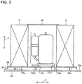
- Fig. 2 is a side view of a vibration isolation structure of the geothermal heat pump system according to Embodiment 1 of the present disclosure.
- Fig. 3 is a plan view of the vibration isolation structure of the geothermal heat pump system according to Embodiment 1 of the present disclosure.
- the direction of arrow X is the width direction of the geothermal heat pump system 30, the direction of arrow Y is the depth direction of the geothermal heat pump system 30, and the direction of arrow Z is the height direction of the geothermal heat pump system 30.
- the structure including the compressor 1 of the geothermal heat pump system 30 will be described with reference to Figs. 2 and 3 .
- the geothermal heat pump system 30 includes a housing 33 and a vibration isolation support base 34 that is provided on a bottom surface 33a of the housing 33 and that supports the compressor 1 and other components.
- the compressor 1 is provided with a vibration isolator 37, and is placed on the vibration isolation support base 34 with the vibration isolator 37 disposed between the compressor 1 and the vibration isolation support base 34.
- the vibration isolation support base 34 includes a vibration isolation unit 35 and a base part 36 on which the compressor 1 and other components are placed, and supports the plurality of components placed on the base part 36.
- the base part 36 is composed of, for example, a plate-shaped unit, such as a metal plate. At least the compressor 1, the primary heat exchanger 4, and the secondary heat exchanger 2 are placed on the base part 36.
- the vibration isolation unit 35 is composed of, for example, a plurality of elastic bodies 35a, and supports the base part 36.
- the vibration isolator 37 provided to the compressor 1 is composed of, for example, a plurality of elastic elements 37a, and is disposed below the bottom surface of the compressor 1.
- the elastic bodies 35a of the vibration isolation unit 35 and the elastic elements 37a of the vibration isolator 37 are each made of, for example, vibration isolation rubber.
- vibration isolation support base 34 including the vibration isolation unit 35 supports the compressor 1, the primary heat exchanger 4, and the secondary heat exchanger 2 in a vibration-isolated manner as described above, vibration of the compressor 1 is not easily transmitted to the housing 33 through the vibration isolation support base 34.
- vibration of the compressor 1 is not easily transmitted to the base part 36.
- the vibration transmission path from the compressor 1 to the housing 33 is interrupted twice so that vibration and noise due to vibration are reduced.
- the compressor 1 is disposed at the center of the housing 33 in the depth direction (direction of arrow Y).
- the primary heat exchanger 4 is disposed in front of the compressor 1, and the secondary heat exchanger 2 is disposed behind the compressor 1 in the depth direction (direction of arrow Y).
- the primary heat exchanger 4 and the secondary heat exchanger 2 each have a cuboid shape, and are each disposed in such a manner that the surface of the cuboid shape having the largest area faces the compressor 1.
- the primary heat exchanger 4 and the secondary heat exchanger 2 are also used as soundproof elements for the compressor 1.
- the primary heat exchanger 4 and the secondary heat exchanger 2 are each composed of, for example, a plate heat exchanger that exchanges heat between a heat medium in a liquid state and refrigerant, and therefore have less gaps compared to those in an air heat exchanger that exchanges heat between air and refrigerant. Accordingly, high soundproofing performance can be achieved.
- the geothermal heat pump system 30 further includes soundproof walls 38 that obstruct the passage of noise generated by the compressor 1.
- the soundproof walls 38 include, for example, three plate-shaped parts arranged to cover portions of side surfaces and an upper surface of the compressor 1 that are not covered by the primary heat exchanger 4 or the secondary heat exchanger 2.
- the compressor 1 placed on the vibration isolation support base 34 is covered by the primary heat exchanger 4, the secondary heat exchanger 2, and the soundproof walls 38 so that leakage of sound generated by the compressor 1 to the outside of the housing 33 through air can be reduced.
- the soundproof walls 38 may be omitted.
- the arrangement and structure of the plurality of elastic bodies 35a included in the vibration isolation unit 35 will be described below.
- the vibration isolation effect is usually reduced when load is unevenly applied to the vibration isolation unit. Therefore, the plurality of elastic bodies 35a are arranged so that load is evenly applied to the vibration isolation unit 35 depending on the arrangement of the components on the base part 36.
- four elastic bodies 35a are disposed below the compressor 1, and three elastic bodies 35a are disposed below each of the primary heat exchanger 4 and the secondary heat exchanger 2 with constant intervals between the three elastic bodies 35a.
- the primary heat exchanger 4 and the secondary heat exchanger 2 may be supported with the same number of elastic bodies 35a as described above so that load can be evenly applied to the vibration isolation unit 35 between the position where the primary heat exchanger 4 is placed and the position where the secondary heat exchanger 2 is placed.
- the arrangement in which load is evenly applied is not limited to an arrangement in which the applied load is exactly constant over the entire region of the vibration isolation unit 35. A vibration isolation effect similar to that described above can be obtained when the applied load is substantially constant.
- Fig. 4 is a plan view of another example of the vibration isolation structure of the geothermal heat pump system according to Embodiment 1 of the present disclosure.
- Fig. 4 shows the case in which the weight of the primary heat exchanger 4 is greater than the weight of the secondary heat exchanger 2.
- Six elastic bodies 35a are disposed below the primary heat exchanger 4, and three elastic bodies 35a are disposed below the secondary heat exchanger 2.
- the number of elastic bodies 35a disposed below each heat exchanger may be set on the basis of the weight of the heat exchanger as described above so that load can be substantially evenly applied to the vibration isolation unit 35 between the positions where the primary heat exchanger 4 and the secondary heat exchanger 2 are placed.
- the vibration isolation unit 35 may include a plurality of types of elastic bodies 35a, such as springs and rubber elements.
- the vibration isolation unit 35 may include the same type of the plurality of elastic bodies 35a having different moduli of elasticity depending on the weights of the components to be supported.
- elastic bodies 35a having a first modulus of elasticity E1 are disposed below the primary heat exchanger 4
- elastic bodies 35a having a second modulus of elasticity E2 that differs from the first modulus of elasticity E1 are disposed below the secondary heat exchanger 2.
- the first modulus of elasticity E1 is set to be greater than the second modulus of elasticity E2.
- Vibration and noise of the compressor 1 can be reduced as described above as long as the base part 36 of the vibration isolation support base 34 has an area sufficient to place at least the compressor 1, the primary heat exchanger 4, and the secondary heat exchanger 2.
- the base part 36 is enlarged to allow some more of the components of the circuits to be placed on the base part 36 in addition to the compressor 1, the primary heat exchanger 4, and the secondary heat exchanger 2, the mass of the base part 36 itself can be reduced.
- the mass of the base part 36 usually needs to be increased to isolate vibration. However, when the thickness of the base part 36 is simply increased, the weight or size of the housing 33 is increased. When the number of components placed on the base part 36 of the vibration isolation support base 34 is increased, the amplitude of vibration transmitted to the base part 36 can be reduced. Thus, vibration can be reduced without increasing the mass of the base part 36, and high vibration isolation effect can be achieved.
- components that are vibration sources such as the pressure reducing device 3, the secondary pump 9, and the primary pump 5, may be placed on the vibration isolation support base 34 in addition to the compressor 1, the primary heat exchanger 4, and the secondary heat exchanger 2.
- the vibration isolation effect of the vibration isolation unit 35 can be enhanced by the masses of the components so that transmission of vibrations of the components can be reduced.
- the vibration isolation structure can be simplified.
- FIG. 5 is a side view of another example of the vibration isolation structure of the geothermal heat pump system according to Embodiment 1 of the present disclosure.
- a vibration isolation support base 134 is composed of, for example, a plate-shaped elastic body, such as a rubber sheet
- the vibration isolation support base 134 is used as both the above-described vibration isolation unit 35 and the above-described base part 36. More specifically, the plate-shaped elastic body is capable of supporting the components including the compressor 1, the primary heat exchanger 4, and the secondary heat exchanger 2 in a vibration-isolated manner.
- the geothermal heat pump system 30 includes the vibration isolation support base 34 including the vibration isolation unit 35, and two heat exchangers that each exchange heat between a heat medium in a liquid state and refrigerant are placed on the vibration isolation support base 34 together with the compressor 1 provided with the vibration isolator 37. Accordingly, sound generated by the compressor 1 can be partially blocked by the two heat exchangers. Therefore, the area in which a soundproof material is provided can be partially reduced, and the size of the vibration isolation support base 34 can be reduced accordingly.
- the two heat exchangers are placed on the vibration isolation support base 34, the two heat exchangers are used as masses on the vibration isolation support base 34 so that sufficient vibration isolation performance can be achieved without increasing the thickness of the vibration isolation support base 34. Therefore, the size of the housing 33 can be reduced, and noise and vibration transmitted from the compressor 1 can also be reduced.
- the compressor 1 is disposed between the primary heat exchanger 4 and the secondary heat exchanger 2. Accordingly, noise due to direct sound from the compressor 1 can be reduced by the primary heat exchanger 4 and the secondary heat exchanger 2 disposed on both sides of the compressor 1. As a result, the amount of soundproof material can be reduced and the area of the base part 36 can be reduced accordingly so that the size of the geothermal heat pump system 30 can be reduced.
- the vibration isolation support base 34 is composed of a plate-shaped elastic body. In such a case, vibration isolation and support for the components can both be achieved by a single elastic body. Therefore, it is not necessary that the vibration isolation support base 34 include a plurality of parts, and the vibration isolation support base 34 can be easily manufactured.
- the vibration isolation support base 34 includes the base part 36 on which the compressor 1, the primary heat exchanger 4, and the secondary heat exchanger 2 are placed, and the base part 36 is supported by the vibration isolation unit 35 composed of the plurality of elastic bodies 35a.
- the vibration isolation effect thus can be increased by setting the number and arrangement of the plurality of elastic bodies 35a depending on, for example, the arrangement and weights of the components.
- the plurality of elastic bodies 35a are arranged so that load is evenly applied to the vibration isolation unit 35.
- the number and arrangement of the plurality of elastic bodies 35a may be adjusted to prevent a reduction in the vibration isolation performance due to load unevenly applied to the vibration isolation unit 35.
- the vibration isolation structure can be easily changed in response to a change in the arrangement of the components.
- the first modulus of elasticity E1 of the elastic bodies 35a disposed below the primary heat exchanger 4 and the second modulus of elasticity E2 of the elastic bodies 35a disposed below the secondary heat exchanger 2 are set on the basis of the weight of the primary heat exchanger 4 and the weight of the secondary heat exchanger 2. Accordingly, even when the heat exchangers have different weights, load can be evenly applied to the vibration isolation unit 35 by arranging the elastic bodies 35a in such a manner that the elastic bodies 35a below the primary heat exchanger 4 and the elastic bodies 35a below the secondary heat exchanger 2 are equal in number but have different moduli of elasticity. As a result, reduction in the vibration isolation effect can be prevented without increasing the number of elastic bodies 35a, and an increase in cost due to an increase in the number of elastic bodies 35a can be prevented.
- the geothermal heat pump system 30 further includes the soundproof walls 38 arranged to cover the portions of the compressor 1 that are not covered by any of the vibration isolation support base 34, the primary heat exchanger 4, and the secondary heat exchanger 2. Accordingly, the compressor 1 can be covered by the primary heat exchanger 4, the secondary heat exchanger 2, and the soundproof walls 38 so that direct sound from the compressor 1 of the geothermal heat pump system 30, which is installed indoors, can be blocked and noise can be further reduced.
- noise from the compressor 1 is reduced by enclosing the compressor 1 with, for example, soundproof walls. Therefore, the soundproof walls are disposed at four side surfaces of the compressor 1 facing in four directions and an upper surface of the compressor 1.
- some of the soundproof walls can be replaced by the primary heat exchanger 4 and the secondary heat exchanger 2 so that it is not necessary to place the soundproof walls 38 at two surfaces, which are front and back surfaces, of the compressor 1. Therefore, the size of the housing 33 depth direction (direction of arrow Y) of the geothermal heat pump system 30 can be reduced.
- Fig. 6 is a side view of a vibration isolation structure of a geothermal heat pump system according to Embodiment 2 of the present disclosure.
- Embodiment 2 differs from Embodiment 1 in that the geothermal heat pump system 30 additionally includes sound absorbers 39.
- items that are not particularly described are the same as those in Embodiment 1, and the same functions and structures are denoted by the same reference signs.
- the sound absorbers 39 are provided on a surface of the primary heat exchanger 4 that faces the compressor 1, a surface of the secondary heat exchanger 2 that faces the compressor 1, and surfaces of the soundproof walls 38 that face the compressor 1.
- the area in which the sound absorbers 39 are provided is set as appropriate to the sound radiation characteristics of the compressor 1.
- the sound absorbers 39 may either be made solely of open-cell foam, such as felt or sponge, or be made of a laminate obtained by placing open-cell foam on a material having a mass greater than that of the open-cell foam, such as a metal plate or rubber, to adjust the sound absorbing performance.
- felt is flexible in shape and exhibits high sound absorbing performance. Therefore, even when the installation space is limited, felt may be suitably used as the material of the sound absorbers 39.
- the primary heat exchanger 4 and the secondary heat exchanger 2 are each composed of, for example, a plate heat exchanger. Accordingly, the sound absorbers 39 can be disposed on the primary heat exchanger 4 and the secondary heat exchanger 2. If, for example, one or each of the primary heat exchanger 4 and the secondary heat exchanger 2 is an air heat exchanger, no sound absorbers 39 can be disposed on the air heat exchanger as the air heat exchanger needs to allow outside air to pass through the air heat exchanger.
- a plate heat exchanger is heat-insulated more effectively than is an air heat exchanger, and therefore does not easily cause dew condensation on the surfaces of the plate heat exchanger. Accordingly, when the sound absorbers 39 are provided on plate heat exchangers, deterioration of the sound absorbers 39 due to dew condensation water does not easily occur.
- the plate heat exchangers are used as rigid walls having a certain thickness and strength in the housing 33, and provide sound insulation. Therefore, the soundproofing effect can be enhanced by using the sound absorbers 39 together with the plate heat exchangers.
- Embodiments of the present disclosure are not limited to the above-described embodiments, and various modifications are possible.
- the sound absorbers 39 are provided on the primary heat exchanger 4, the secondary heat exchanger 2, and the soundproof walls 38 in Embodiment 2, the sound absorbers 39 may be provided only on the primary heat exchanger 4 and the secondary heat exchanger 2 when no soundproof walls 38 are provided.
- the sound absorbers 39 may be provided also on portions of inner surfaces of the housing 33 that face the compressor 1 in addition to the primary heat exchanger 4 and the secondary heat exchanger 2.
- the arrangement of the primary heat exchanger 4 and the secondary heat exchanger 2 to the compressor 1 may be set as appropriate to the positions of components in the housing 33.
- the primary heat exchanger 4 may be disposed to the right of the compressor 1 and the secondary heat exchanger 2 may be disposed behind the compressor 1 so that the primary heat exchanger 4 and the secondary heat exchanger 2 substantially form an L-shape.
- two surfaces of the compressor 1 are covered with the primary heat exchanger 4 and the secondary heat exchanger 2 so that the amount of the soundproof material can be reduced and noise of the compressor 1 can be reduced by the components of the refrigerant circuit CR.
- the elastic bodies 35a of the vibration isolation unit 35 and the elastic elements 37a of the vibration isolator 37 may have any shape.
- the elastic bodies 35a and the elastic elements 37a may each be rod-shaped and extend in the width direction (direction of arrow X) along the components disposed above the elastic bodies 35a and the elastic elements 37a.
- the primary heat exchanger 4 and the secondary heat exchanger 2 may each have any shape.
Abstract
Description
- The present disclosure relates to a geothermal heat pump system including a refrigerant circuit, and more particularly to a vibration isolation structure.
- Some geothermal heat pump system uses the ground or a lake as a heat source to collect heat by circulating a primary heat medium through an underground heat exchanger, which is installed underground, with a heat pump. The collected heat is supplied to a secondary heat medium that circulates through a load. As underground temperatures are more stable than outside air temperatures throughout the year, the geothermal heat pump system that uses geothermal heat has attracted attention in recent years from the viewpoint of energy efficiency and reduction in CO2 emissions. The geothermal heat pump system includes a refrigerant circuit including a compressor that compresses refrigerant, a primary heat exchanger that exchanges heat between a primary heat medium in a liquid state and the refrigerant, and a secondary heat exchanger that has a secondary heat medium in a liquid state and the refrigerant.
- As the geothermal heat pump system collects and releases heat through the underground heat exchanger, circuit components provided between pipes connected to the load and pipes connected to the underground heat exchanger are usually disposed in the same housing. As the housing of the geothermal heat pump system is installed indoors in a building, unlike an air-conditioning apparatus that is disposed outdoors and provides heat exchange with outside air, the compressor, which is a noise source, is installed indoors. Accordingly, the geothermal heat pump system requires a structure for reducing noise and vibration.
- A technology for reducing transmission of vibration from a compressor of an air-conditioning apparatus has been disclosed (see, for example, Patent Literature 1). The air-conditioning apparatus according to
Patent Literature 1 is structured in such a manner that a compressor provided with vibration isolators, an air heat exchanger provided with vibration isolators, and a water heat exchanger are arranged on the same support unit that is supported by vibration isolators. To reduce noise from the compressor without affecting the supply of outside air to the air heat exchanger, a soundproof box is provided over the support unit to enclose the compressor. - Patent Literature 1: Japanese Unexamined Patent Application Publication No.
2005-241197 - As the housing of the geothermal heat pump system is installed indoors, a reduction in the size of the housing is desired as well as a reduction in vibration and noise. However, according to
Patent Literature 1, the support unit is required to have an installation area for soundproof walls that surround the compressor in addition to installation areas for the compressor, the primary heat exchanger, and the secondary heat exchanger. Thus, when the soundproof box that surrounds the compressor is provided, the width and depth of the housing are increased. When the soundproof box is not provided, noise from the compressor leaks through the air heat exchanger. In addition, when the mass of the support unit is increased by increasing the thickness of the support unit to reduce transmission of vibration of the compressor, the height of the housing is increased. Thus, it is difficult to achieve both a reduction in the size of the housing of the geothermal heat pump system and a reduction in noise and vibration. - The present disclosure has been made to solve the above-described problem, and an object of the present disclosure is to provide a geothermal heat pump system that includes a small housing and in which noise and vibration from the compressor can be reduced.
- A geothermal heat pump system according to an embodiment of the present disclosure includes a refrigerant circuit including a compressor provided with a vibration isolator, a primary heat exchanger that exchanges heat between refrigerant and a primary heat medium that is in a liquid state and uses ground as a heat source, and a secondary heat exchanger that exchanges heat between the refrigerant and a secondary heat medium that is in a liquid state; and a vibration isolation support base that includes a vibration isolation unit and supports the compressor, the primary heat exchanger, and the secondary heat exchanger with the vibration isolation unit disposed between the vibration isolation support base and a set of the compressor, the primary heat exchanger, and the secondary heat exchanger.
- The geothermal heat pump system according to an embodiment of the present disclosure is structured in such a manner that two heat exchangers that each exchange heat between a heat medium in a liquid state and refrigerant are disposed on the vibration isolation support base together with the compressor provided with the vibration isolator. Therefore, noise can be reduced. As a result, the area in which a soundproof material is provided on the vibration isolation support base can be partially reduced, and the area of the vibration isolation support base can be reduced accordingly. In addition, as the two heat exchangers, whose weights are relatively large compared to other components of the refrigerant circuit, are placed on the vibration isolation support base, the two heat exchangers are used as masses on the vibration isolation support base so that sufficient vibration isolation performance can be achieved without increasing the thickness of the vibration isolation support base. Therefore, the size of the housing can be reduced, and noise and vibration transmitted from the compressor can also be reduced.
-
- [
Fig. 1] Fig. 1 is a schematic diagram schematically illustrating the structure of geothermal heat pump systems according toEmbodiments - [
Fig. 2] Fig. 2 is a side view of a vibration isolation structure of the geothermal heat pump system according toEmbodiment 1 of the present disclosure. - [
Fig. 3] Fig. 3 is a plan view of the vibration isolation structure of the geothermal heat pump system according toEmbodiment 1 of the present disclosure. - [
Fig. 4] Fig. 4 is a plan view of another example of the vibration isolation structure of the geothermal heat pump system according toEmbodiment 1 of the present disclosure. - [
Fig. 5] Fig. 5 is a side view of another example of the vibration isolation structure of the geothermal heat pump system according toEmbodiment 1 of the present disclosure. - [
Fig. 6] Fig. 6 is a side view of a vibration isolation structure of the geothermal heat pump system according toEmbodiment 2 of the present disclosure. Description of Embodiments -
Fig. 1 is a schematic diagram schematically illustrating the structure of a geothermal heat pump system according toEmbodiment 1 of the present disclosure. A geothermalheat pump system 30 is installed indoors in a building. As illustrated inFig. 1 , the geothermalheat pump system 30 is connected to anunderground heat exchanger 18 that is installed underground and loads that are installed indoors. The geothermalheat pump system 30 collects geothermal heat through a primary circuit C1 including theunderground heat exchanger 18 with a heat pump, and supplies the collected heat to the loads connected to a secondary circuit C2. - The loads include, for example, a hot water supply load B1 that supplies hot water to, for example, a bath, and an air-conditioning load B2 including a radiator. Brine circulates in the primary circuit C1, and water circulates in the secondary circuit C2. A primary heat medium that flows through the primary circuit C1 and a secondary heat medium that flows through the secondary circuit C2 are each only required to be any liquid fluid. An example in which the primary heat medium is brine and the secondary heat medium is water will be described below.
- The
underground heat exchanger 18 is installed underground, and exchanges heat between the brine and the ground G, which is a heat source. When, for example, the underground temperature is higher than the outside air temperature, the brine is heated by receiving geothermal heat. Theunderground heat exchanger 18 includes a heatcollection pipe group 18a through which the brine circulates. The heatcollection pipe group 18a, which is made of a resin or other substance and is U-shaped, for example, is vertically installed underground. The heat exchange performance of theunderground heat exchanger 18 differs depending on the location and depth at which the heatcollection pipe group 18a is installed even when the size of the heatcollection pipe group 18a is constant. - When a sufficiently large installation area is available, the heat collection pipes may instead be horizontally installed. In such a case, the heat collection pipes are bent a plurality of times in a meandering manner so that the heat collection pipes are in contact with the ground G over an area greater than or equal to a certain area. To minimize the influence of the temperature variation at the ground surface due to the air temperature, solar radiation, precipitation, and snowfall, the heat collection pipes are installed at or below a certain depth.
- The geothermal
heat pump system 30 includes aheat pump device 31 that performs a heat pump cycle operation, a hotwater heating device 32 that supplies hot water to the loads, acontroller 20, and aremote controller 21 operated by a user. Theheat pump device 31 has various components of a refrigerant circuit CR and some components of the primary circuit C1 mounted in theheat pump device 31. The refrigerant circuit CR is formed by sequentially connecting aprimary heat exchanger 4, acompressor 1 that circulates refrigerant through the refrigerant circuit CR, asecondary heat exchanger 2, and apressure reducing device 3 that reduces the pressure of the refrigerant with refrigerant pipes. The brine circulated in the primary circuit C1 flows into theprimary heat exchanger 4, and the water circulated in the secondary circuit C2 flows into thesecondary heat exchanger 2. The refrigerant may be, for example, R410A, which is an HFC based mixed refrigerant, or R32. - The
compressor 1, which compresses the refrigerant, is a variable displacement compressor whose rotation frequency is controlled by an inverter. The primary heat exchanger 4 exchanges heat between the brine in the primary circuit C1 and the refrigerant in the refrigerant circuit CR. In a heating operation, theprimary heat exchanger 4 is used as an evaporator to heat and evaporate the refrigerant by using geothermal heat received by the brine. Theprimary heat exchanger 4 is composed of, for example, a plate heat exchanger in which a plurality of plates are stacked. Theprimary heat exchanger 4 may instead be composed of a double tube heat exchanger including a heat transfer tube through which the refrigerant flows and a heat transfer tube through which water flows. - The
pressure reducing device 3 is composed of, for example, an electronic expansion valve having a variable opening degree. Thesecondary heat exchanger 2 exchanges heat between the water in the secondary circuit C2 and the refrigerant in the refrigerant circuit CR. In the heating operation, thesecondary heat exchanger 2 is used as a condenser to generate hot water by heating the water with the refrigerant heated by the geothermal heat. Thesecondary heat exchanger 2 is composed of, for example, a plate heat exchanger. Thesecondary heat exchanger 2 may instead be composed of a double tube heat exchanger. - The primary circuit C1 is formed by connecting a
primary pump 5 that circulates the brine in the primary circuit C1, theprimary heat exchanger 4, and theunderground heat exchanger 18 with pipes. Theprimary pump 5 is mounted in theheat pump device 31 together with the above-describedprimary heat exchanger 4. - A plurality of sensors for detecting the operational state of the primary circuit C1 are mounted in the
heat pump device 31, and the sensors include a firstflow rate sensor 6, aninlet temperature sensor 7, and anoutlet temperature sensor 8. The firstflow rate sensor 6 measures the flow rate of the brine that circulates in the primary circuit C1. Theinlet temperature sensor 7 is provided at a brine inlet of theprimary heat exchanger 4 and measures the temperature of the brine that flows into the primary heat exchanger 4 (inlet temperature). Thus, theinlet temperature sensor 7 measures the temperature of the brine that has exchanged heat with the ground in theunderground heat exchanger 18 and has been drawn up by theprimary pump 5. Theoutlet temperature sensor 8 is provided at a brine outlet of theprimary heat exchanger 4 and measures the temperature of the brine that flows out of the primary heat exchanger 4 (outlet temperature). Theinlet temperature sensor 7 and theoutlet temperature sensor 8 are each composed of, for example, a thermistor. - The hot
water heating device 32 has various devices of the secondary circuit C2 mounted in the hotwater heating device 32. The secondary circuit C2 is formed by connecting asecondary pump 9, thesecondary heat exchanger 2, anelectric heater 10, aflow switching device 11, and ahot water tank 12 with pipes. Thesecondary pump 9 circulates water in the secondary circuit C2. In the heating operation, theelectric heater 10 heats the hot water generated by heating the water in thesecondary heat exchanger 2. Theflow switching device 11 is composed of, for example, a three-way valve, and sets the destination of the hot water to one of the hot water supply load B1 and the air-conditioning load B2. - The
hot water tank 12 is provided between theflow switching device 11 and the hot water supply load B1 in the secondary circuit C2. Thehot water tank 12 is substantially cylindrical, and at least the shell of thehot water tank 12 is made of a metal material, such as stainless steel. Thehot water tank 12 is covered with a heat insulating material to reduce heat dissipation from water stored in thehot water tank 12. - A
water supply pipe 12a, which is connected to, for example, an external water supply, is connected to a lower portion of thehot water tank 12, and water is supplied from an external water source to thehot water tank 12 through thewater supply pipe 12a and stored in thehot water tank 12. In a water-heating operation, the water stored in thehot water tank 12 is heated by the hot water that circulates in the secondary circuit C2. The water stored in thehot water tank 12 has a temperature stratification in such a manner that the temperature of the water stored in thehot water tank 12 is high in an upper region and low in a lower region. A hot-water discharge pipe 12b, which is connected to the hot water supply load B1, is connected to an upper portion of thehot water tank 12. The water stored in thehot water tank 12 is supplied to the hot water supply load B1 through the hot-water discharge pipe 12b. - A plurality of sensors for detecting the operational state of the secondary circuit C2 are mounted in the hot
water heating device 32, and the sensors include a secondflow rate sensor 13, aforward temperature sensor 14, areturn temperature sensor 15, and atank temperature sensor 16. The secondflow rate sensor 13 measures the flow rate of the water that circulates in the secondary circuit C2. Theforward temperature sensor 14 measures the temperature of the water that flows into the secondary heat exchanger 2 (forward temperature). Thereturn temperature sensor 15 measures the temperature of the generated hot water (return temperature). Thetank temperature sensor 16 detects the temperature of the water stored in thehot water tank 12. Theinlet temperature sensor 7, theoutlet temperature sensor 8, and thetank temperature sensor 16 are each composed of, for example, a thermistor. - The above-described
controller 20 is also mounted in the hotwater heating device 32. Thecontroller 20 is composed of, for example, a microcomputer, and controls the overall operation of the geothermalheat pump system 30. Thecontroller 20 is connected to theremote controller 21 wirelessly, or with wires, and receives an operation command input to thecontroller 20 by the user through theremote controller 21. Thecontroller 20 also receives measurement information obtained by the plurality of sensors that detect the operational state of the primary circuit C1 and the plurality of sensors that detect the operational state of the secondary circuit C2. Thecontroller 20 controls the refrigerant circuit CR, the primary circuit C1, and the secondary circuit C2 in accordance with, for example, the operation command and the measurement information input to thecontroller 20. - More specifically, the
controller 20 controls the operation frequency of thecompressor 1, the opening degree of thepressure reducing device 3, the rotation frequency of theprimary pump 5, the rotation frequency of thesecondary pump 9, and energization of theelectric heater 10 on the basis of, for example, the measurement information so that hot water required by the loads is supplied. Thecontroller 20 controls the switching operation of theflow switching device 11 in accordance with the operation command. - The operation of the geothermal
heat pump system 30 will be described below with reference toFig. 1 . InFig. 1 , the direction of arrow F1 is the direction in which the brine flows, the direction of arrow FR is the direction in which the refrigerant flows, and the direction arrow F2 is the direction in which the water flows. The geothermalheat pump system 30 performs a heating operation when the water-heating operation is performed to heat the water stored in thehot water tank 12 or when heating is required by the air-conditioning load B2. - In the heating operation, high-temperature high-pressure gas refrigerant discharged from the
compressor 1 flows in the direction of arrow FR and flows into thesecondary heat exchanger 2. The refrigerant that has flowed into thesecondary heat exchanger 2 is condensed and liquefied into high-pressure low-temperature liquid refrigerant while dissipating heat in thesecondary heat exchanger 2. At this time, the water that flows through the secondary circuit C2 is heated by the heat dissipated by the refrigerant so that hot water is obtained. The high-pressure low-temperature refrigerant that flows out of thesecondary heat exchanger 2 is reduced in pressure by thepressure reducing device 3, and flows into theprimary heat exchanger 4. The refrigerant that has flowed into theprimary heat exchanger 4 receives heat from the heat medium that flows through the primary circuit C1 in theprimary heat exchanger 4, and is evaporated and gasified. Then, the refrigerant flows out of theprimary heat exchanger 4 and is suctioned into thecompressor 1. The above-described cycle of the refrigerant circuit CR continues during the heating operation of the geothermalheat pump system 30. - The hot water generated by heating the water in the
secondary heat exchanger 2 flows through theelectric heater 10 and reaches theflow switching device 11. When heating is required by the air-conditioning load B2, theflow switching device 11 sets the destination of the hot water to the air-conditioning load B2. Accordingly, the hot water is circulated through the radiator, which is installed in a room, to heat the room. When the water-heating operation for heating the water stored in thehot water tank 12 is required, theflow switching device 11 sets the destination of the hot water to thehot water tank 12. Accordingly, the hot water is circulated through thehot water tank 12 so that the water stored in thehot water tank 12 is heated. After the water flows through the radiator in the room or thehot water tank 12 and the temperature of the water is reduced, the water is caused to flow into thesecondary heat exchanger 2 by thesecondary pump 9, and is heated into hot water by thesecondary heat exchanger 2 again. The above-described cycle of the secondary circuit C2 continues during the heating operation of the geothermalheat pump system 30. - As described above, the geothermal
heat pump system 30 exchanges heat between the refrigerant in the refrigerant circuit CR and the brine in the primary circuit C1 and between the refrigerant in the refrigerant circuit CR and the water in the secondary circuit C2, thereby collecting geothermal heat and supplying the collected heat to the loads. -
Fig. 2 is a side view of a vibration isolation structure of the geothermal heat pump system according toEmbodiment 1 of the present disclosure.Fig. 3 is a plan view of the vibration isolation structure of the geothermal heat pump system according toEmbodiment 1 of the present disclosure. The direction of arrow X is the width direction of the geothermalheat pump system 30, the direction of arrow Y is the depth direction of the geothermalheat pump system 30, and the direction of arrow Z is the height direction of the geothermalheat pump system 30. The structure including thecompressor 1 of the geothermalheat pump system 30 will be described with reference toFigs. 2 and3 . - The geothermal
heat pump system 30 includes ahousing 33 and a vibrationisolation support base 34 that is provided on abottom surface 33a of thehousing 33 and that supports thecompressor 1 and other components. Thecompressor 1 is provided with a vibration isolator 37, and is placed on the vibrationisolation support base 34 with the vibration isolator 37 disposed between thecompressor 1 and the vibrationisolation support base 34. - The vibration
isolation support base 34 includes avibration isolation unit 35 and abase part 36 on which thecompressor 1 and other components are placed, and supports the plurality of components placed on thebase part 36. Thebase part 36 is composed of, for example, a plate-shaped unit, such as a metal plate. At least thecompressor 1, theprimary heat exchanger 4, and thesecondary heat exchanger 2 are placed on thebase part 36. Thevibration isolation unit 35 is composed of, for example, a plurality ofelastic bodies 35a, and supports thebase part 36. - The vibration isolator 37 provided to the
compressor 1 is composed of, for example, a plurality ofelastic elements 37a, and is disposed below the bottom surface of thecompressor 1. Theelastic bodies 35a of thevibration isolation unit 35 and theelastic elements 37a of the vibration isolator 37 are each made of, for example, vibration isolation rubber. - As the vibration
isolation support base 34 including thevibration isolation unit 35 supports thecompressor 1, theprimary heat exchanger 4, and thesecondary heat exchanger 2 in a vibration-isolated manner as described above, vibration of thecompressor 1 is not easily transmitted to thehousing 33 through the vibrationisolation support base 34. In addition, as thecompressor 1 is placed on the vibrationisolation support base 34 with the vibration isolator 37 disposed between thecompressor 1 and the vibrationisolation support base 34, vibration of thecompressor 1 is not easily transmitted to thebase part 36. Thus, the vibration transmission path from thecompressor 1 to thehousing 33 is interrupted twice so that vibration and noise due to vibration are reduced. In addition, as theprimary heat exchanger 4 and thesecondary heat exchanger 2, whose masses are relatively large compared to those of a plurality of other components of the circuits of the geothermalheat pump system 30, are placed on the vibrationisolation support base 34, vibration of the vibrationisolation support base 34 is reduced. - The arrangement of the components on the vibration
isolation support base 34 will be described below. Thecompressor 1 is disposed at the center of thehousing 33 in the depth direction (direction of arrow Y). Theprimary heat exchanger 4 is disposed in front of thecompressor 1, and thesecondary heat exchanger 2 is disposed behind thecompressor 1 in the depth direction (direction of arrow Y). Theprimary heat exchanger 4 and thesecondary heat exchanger 2 each have a cuboid shape, and are each disposed in such a manner that the surface of the cuboid shape having the largest area faces thecompressor 1. When thecompressor 1, theprimary heat exchanger 4, and thesecondary heat exchanger 2 are disposed in this manner, theprimary heat exchanger 4 and thesecondary heat exchanger 2 are also used as soundproof elements for thecompressor 1. - As described above, the
primary heat exchanger 4 and thesecondary heat exchanger 2 are each composed of, for example, a plate heat exchanger that exchanges heat between a heat medium in a liquid state and refrigerant, and therefore have less gaps compared to those in an air heat exchanger that exchanges heat between air and refrigerant. Accordingly, high soundproofing performance can be achieved. - The geothermal
heat pump system 30 further includessoundproof walls 38 that obstruct the passage of noise generated by thecompressor 1. Thesoundproof walls 38 include, for example, three plate-shaped parts arranged to cover portions of side surfaces and an upper surface of thecompressor 1 that are not covered by theprimary heat exchanger 4 or thesecondary heat exchanger 2. Thus, thecompressor 1 placed on the vibrationisolation support base 34 is covered by theprimary heat exchanger 4, thesecondary heat exchanger 2, and thesoundproof walls 38 so that leakage of sound generated by thecompressor 1 to the outside of thehousing 33 through air can be reduced. - When the dimensions of the
primary heat exchanger 4 and thesecondary heat exchanger 2 in the height direction (direction of arrow Z) and the width direction (direction of arrow X) are sufficiently greater than those of thecompressor 1 so that a sufficient soundproofing effect can be achieved by theprimary heat exchanger 4, thesecondary heat exchanger 2, thehousing 33, and other components, thesoundproof walls 38 may be omitted. - The arrangement and structure of the plurality of
elastic bodies 35a included in thevibration isolation unit 35 will be described below. The vibration isolation effect is usually reduced when load is unevenly applied to the vibration isolation unit. Therefore, the plurality ofelastic bodies 35a are arranged so that load is evenly applied to thevibration isolation unit 35 depending on the arrangement of the components on thebase part 36. As illustrated inFig. 3 , fourelastic bodies 35a are disposed below thecompressor 1, and threeelastic bodies 35a are disposed below each of theprimary heat exchanger 4 and thesecondary heat exchanger 2 with constant intervals between the threeelastic bodies 35a. When theprimary heat exchanger 4 and thesecondary heat exchanger 2 have substantially the same weight, theprimary heat exchanger 4 and thesecondary heat exchanger 2 may be supported with the same number ofelastic bodies 35a as described above so that load can be evenly applied to thevibration isolation unit 35 between the position where theprimary heat exchanger 4 is placed and the position where thesecondary heat exchanger 2 is placed. The arrangement in which load is evenly applied is not limited to an arrangement in which the applied load is exactly constant over the entire region of thevibration isolation unit 35. A vibration isolation effect similar to that described above can be obtained when the applied load is substantially constant. -
Fig. 4 is a plan view of another example of the vibration isolation structure of the geothermal heat pump system according toEmbodiment 1 of the present disclosure.Fig. 4 shows the case in which the weight of theprimary heat exchanger 4 is greater than the weight of thesecondary heat exchanger 2. Sixelastic bodies 35a are disposed below theprimary heat exchanger 4, and threeelastic bodies 35a are disposed below thesecondary heat exchanger 2. When theprimary heat exchanger 4 and thesecondary heat exchanger 2 have different weights, the number ofelastic bodies 35a disposed below each heat exchanger may be set on the basis of the weight of the heat exchanger as described above so that load can be substantially evenly applied to thevibration isolation unit 35 between the positions where theprimary heat exchanger 4 and thesecondary heat exchanger 2 are placed. - When the
primary heat exchanger 4 and thesecondary heat exchanger 2 have different weights, thevibration isolation unit 35 may include a plurality of types ofelastic bodies 35a, such as springs and rubber elements. Alternatively, thevibration isolation unit 35 may include the same type of the plurality ofelastic bodies 35a having different moduli of elasticity depending on the weights of the components to be supported. For example,elastic bodies 35a having a first modulus of elasticity E1 are disposed below theprimary heat exchanger 4, andelastic bodies 35a having a second modulus of elasticity E2 that differs from the first modulus of elasticity E1 are disposed below thesecondary heat exchanger 2. More specifically, when the weight of theprimary heat exchanger 4 is greater than the weight of thesecondary heat exchanger 2, the first modulus of elasticity E1 is set to be greater than the second modulus of elasticity E2. With such a structure, even when the weight is not even, load can be substantially evenly applied to thevibration isolation unit 35 by arranging theelastic bodies 35a in such a manner that theelastic bodies 35a below theprimary heat exchanger 4 and theelastic bodies 35a below thesecondary heat exchanger 2 are equal in number but have different moduli of elasticity. - Vibration and noise of the
compressor 1 can be reduced as described above as long as thebase part 36 of the vibrationisolation support base 34 has an area sufficient to place at least thecompressor 1, theprimary heat exchanger 4, and thesecondary heat exchanger 2. However, when thebase part 36 is enlarged to allow some more of the components of the circuits to be placed on thebase part 36 in addition to thecompressor 1, theprimary heat exchanger 4, and thesecondary heat exchanger 2, the mass of thebase part 36 itself can be reduced. - The mass of the
base part 36 usually needs to be increased to isolate vibration. However, when the thickness of thebase part 36 is simply increased, the weight or size of thehousing 33 is increased. When the number of components placed on thebase part 36 of the vibrationisolation support base 34 is increased, the amplitude of vibration transmitted to thebase part 36 can be reduced. Thus, vibration can be reduced without increasing the mass of thebase part 36, and high vibration isolation effect can be achieved. - In such a case, components that are vibration sources, such as the
pressure reducing device 3, thesecondary pump 9, and theprimary pump 5, may be placed on the vibrationisolation support base 34 in addition to thecompressor 1, theprimary heat exchanger 4, and thesecondary heat exchanger 2. With such a structure, the vibration isolation effect of thevibration isolation unit 35 can be enhanced by the masses of the components so that transmission of vibrations of the components can be reduced. In addition, the vibration isolation structure can be simplified. - Each of the above-described
vibration isolation unit 35 of the vibrationisolation support base 34 and the above-described vibration isolator 37 provided to thecompressor 1 may instead be composed of, for example, a single vibration isolation rubber element.Fig. 5 is a side view of another example of the vibration isolation structure of the geothermal heat pump system according toEmbodiment 1 of the present disclosure. When a vibrationisolation support base 134 is composed of, for example, a plate-shaped elastic body, such as a rubber sheet, the vibrationisolation support base 134 is used as both the above-describedvibration isolation unit 35 and the above-describedbase part 36. More specifically, the plate-shaped elastic body is capable of supporting the components including thecompressor 1, theprimary heat exchanger 4, and thesecondary heat exchanger 2 in a vibration-isolated manner. - As described above, the geothermal
heat pump system 30 according toEmbodiment 1 includes the vibrationisolation support base 34 including thevibration isolation unit 35, and two heat exchangers that each exchange heat between a heat medium in a liquid state and refrigerant are placed on the vibrationisolation support base 34 together with thecompressor 1 provided with the vibration isolator 37. Accordingly, sound generated by thecompressor 1 can be partially blocked by the two heat exchangers. Therefore, the area in which a soundproof material is provided can be partially reduced, and the size of the vibrationisolation support base 34 can be reduced accordingly. In addition, as the two heat exchangers are placed on the vibrationisolation support base 34, the two heat exchangers are used as masses on the vibrationisolation support base 34 so that sufficient vibration isolation performance can be achieved without increasing the thickness of the vibrationisolation support base 34. Therefore, the size of thehousing 33 can be reduced, and noise and vibration transmitted from thecompressor 1 can also be reduced. - The
compressor 1 is disposed between theprimary heat exchanger 4 and thesecondary heat exchanger 2. Accordingly, noise due to direct sound from thecompressor 1 can be reduced by theprimary heat exchanger 4 and thesecondary heat exchanger 2 disposed on both sides of thecompressor 1. As a result, the amount of soundproof material can be reduced and the area of thebase part 36 can be reduced accordingly so that the size of the geothermalheat pump system 30 can be reduced. - The vibration
isolation support base 34 is composed of a plate-shaped elastic body. In such a case, vibration isolation and support for the components can both be achieved by a single elastic body. Therefore, it is not necessary that the vibrationisolation support base 34 include a plurality of parts, and the vibrationisolation support base 34 can be easily manufactured. - The vibration
isolation support base 34 includes thebase part 36 on which thecompressor 1, theprimary heat exchanger 4, and thesecondary heat exchanger 2 are placed, and thebase part 36 is supported by thevibration isolation unit 35 composed of the plurality ofelastic bodies 35a. The vibration isolation effect thus can be increased by setting the number and arrangement of the plurality ofelastic bodies 35a depending on, for example, the arrangement and weights of the components. - The plurality of
elastic bodies 35a are arranged so that load is evenly applied to thevibration isolation unit 35. Thus, the number and arrangement of the plurality ofelastic bodies 35a may be adjusted to prevent a reduction in the vibration isolation performance due to load unevenly applied to thevibration isolation unit 35. In addition, the vibration isolation structure can be easily changed in response to a change in the arrangement of the components. - The first modulus of elasticity E1 of the
elastic bodies 35a disposed below theprimary heat exchanger 4 and the second modulus of elasticity E2 of theelastic bodies 35a disposed below thesecondary heat exchanger 2 are set on the basis of the weight of theprimary heat exchanger 4 and the weight of thesecondary heat exchanger 2. Accordingly, even when the heat exchangers have different weights, load can be evenly applied to thevibration isolation unit 35 by arranging theelastic bodies 35a in such a manner that theelastic bodies 35a below theprimary heat exchanger 4 and theelastic bodies 35a below thesecondary heat exchanger 2 are equal in number but have different moduli of elasticity. As a result, reduction in the vibration isolation effect can be prevented without increasing the number ofelastic bodies 35a, and an increase in cost due to an increase in the number ofelastic bodies 35a can be prevented. - The geothermal
heat pump system 30 further includes thesoundproof walls 38 arranged to cover the portions of thecompressor 1 that are not covered by any of the vibrationisolation support base 34, theprimary heat exchanger 4, and thesecondary heat exchanger 2. Accordingly, thecompressor 1 can be covered by theprimary heat exchanger 4, thesecondary heat exchanger 2, and thesoundproof walls 38 so that direct sound from thecompressor 1 of the geothermalheat pump system 30, which is installed indoors, can be blocked and noise can be further reduced. - According to the related art, noise from the
compressor 1 is reduced by enclosing thecompressor 1 with, for example, soundproof walls. Therefore, the soundproof walls are disposed at four side surfaces of thecompressor 1 facing in four directions and an upper surface of thecompressor 1. In contrast, in the above-described geothermalheat pump system 30, some of the soundproof walls can be replaced by theprimary heat exchanger 4 and thesecondary heat exchanger 2 so that it is not necessary to place thesoundproof walls 38 at two surfaces, which are front and back surfaces, of thecompressor 1. Therefore, the size of thehousing 33 depth direction (direction of arrow Y) of the geothermalheat pump system 30 can be reduced. -
Fig. 6 is a side view of a vibration isolation structure of a geothermal heat pump system according toEmbodiment 2 of the present disclosure.Embodiment 2 differs fromEmbodiment 1 in that the geothermalheat pump system 30 additionally includessound absorbers 39. InEmbodiment 2, items that are not particularly described are the same as those inEmbodiment 1, and the same functions and structures are denoted by the same reference signs. - With reference to
Fig. 6 , thesound absorbers 39 are provided on a surface of theprimary heat exchanger 4 that faces thecompressor 1, a surface of thesecondary heat exchanger 2 that faces thecompressor 1, and surfaces of thesoundproof walls 38 that face thecompressor 1. The area in which thesound absorbers 39 are provided is set as appropriate to the sound radiation characteristics of thecompressor 1. The sound absorbers 39 may either be made solely of open-cell foam, such as felt or sponge, or be made of a laminate obtained by placing open-cell foam on a material having a mass greater than that of the open-cell foam, such as a metal plate or rubber, to adjust the sound absorbing performance. Among the examples of the material of thesound absorbers 39, felt is flexible in shape and exhibits high sound absorbing performance. Therefore, even when the installation space is limited, felt may be suitably used as the material of thesound absorbers 39. - As described above, the
primary heat exchanger 4 and thesecondary heat exchanger 2 are each composed of, for example, a plate heat exchanger. Accordingly, thesound absorbers 39 can be disposed on theprimary heat exchanger 4 and thesecondary heat exchanger 2. If, for example, one or each of theprimary heat exchanger 4 and thesecondary heat exchanger 2 is an air heat exchanger, nosound absorbers 39 can be disposed on the air heat exchanger as the air heat exchanger needs to allow outside air to pass through the air heat exchanger. - In particular, a plate heat exchanger is heat-insulated more effectively than is an air heat exchanger, and therefore does not easily cause dew condensation on the surfaces of the plate heat exchanger. Accordingly, when the
sound absorbers 39 are provided on plate heat exchangers, deterioration of thesound absorbers 39 due to dew condensation water does not easily occur. In addition, the plate heat exchangers are used as rigid walls having a certain thickness and strength in thehousing 33, and provide sound insulation. Therefore, the soundproofing effect can be enhanced by using thesound absorbers 39 together with the plate heat exchangers. - Embodiments of the present disclosure are not limited to the above-described embodiments, and various modifications are possible. For example, although the
sound absorbers 39 are provided on theprimary heat exchanger 4, thesecondary heat exchanger 2, and thesoundproof walls 38 inEmbodiment 2, thesound absorbers 39 may be provided only on theprimary heat exchanger 4 and thesecondary heat exchanger 2 when nosoundproof walls 38 are provided. Alternatively, thesound absorbers 39 may be provided also on portions of inner surfaces of thehousing 33 that face thecompressor 1 in addition to theprimary heat exchanger 4 and thesecondary heat exchanger 2. - Although an example has been described in which the
primary heat exchanger 4 and thesecondary heat exchanger 2 are arranged to face each other with thecompressor 1 placed between theprimary heat exchanger 4 and thesecondary heat exchanger 2, the arrangement of theprimary heat exchanger 4 and thesecondary heat exchanger 2 to thecompressor 1 may be set as appropriate to the positions of components in thehousing 33. For example, theprimary heat exchanger 4 may be disposed to the right of thecompressor 1 and thesecondary heat exchanger 2 may be disposed behind thecompressor 1 so that theprimary heat exchanger 4 and thesecondary heat exchanger 2 substantially form an L-shape. Also in this case, two surfaces of thecompressor 1 are covered with theprimary heat exchanger 4 and thesecondary heat exchanger 2 so that the amount of the soundproof material can be reduced and noise of thecompressor 1 can be reduced by the components of the refrigerant circuit CR. - The
elastic bodies 35a of thevibration isolation unit 35 and theelastic elements 37a of the vibration isolator 37 may have any shape. For example, theelastic bodies 35a and theelastic elements 37a may each be rod-shaped and extend in the width direction (direction of arrow X) along the components disposed above theelastic bodies 35a and theelastic elements 37a. - Although an example in which the
primary heat exchanger 4 and thesecondary heat exchanger 2 each have a cuboid shape is described above, theprimary heat exchanger 4 and thesecondary heat exchanger 2 may each have any shape. Reference Signs List - 1
compressor 2secondary heat exchanger 3pressure reducing device 4primary heat exchanger 5primary pump 6 firstflow rate sensor 7inlet temperature sensor 8outlet temperature sensor 9secondary pump 10electric heater 11flow switching device 12hot water tank 12awater supply pipe 12b hot-water discharge pipe 13 secondflow rate sensor 14temperature sensor 15return temperature sensor 16tank temperature sensor 18underground heat exchanger 18a heatcollection pipe group 20controller 21remote controller 30 geothermalheat pump system 31heat pump device 32 hotwater heating device 33housing 33a bottom surface 34 vibrationisolation support base 35vibration isolation unit 35aelastic body 36 base part 37vibration isolator 37aelastic element 38soundproof wall 39sound absorber 134 vibration isolation support base B1 hot water supply load B2 air-conditioning load C1 primary circuit C2 secondary circuit CR refrigerant circuit E1 first modulus of elasticity E2 second modulus of elasticity G ground
Claims (9)
- A geothermal heat pump system, comprising:a refrigerant circuit including a compressor provided with a vibration isolator, a primary heat exchanger that exchanges heat between refrigerant and a primary heat medium that is in a liquid state and uses ground as a heat source, and a secondary heat exchanger that exchanges heat between the refrigerant and a secondary heat medium that is in a liquid state; anda vibration isolation support base that includes a vibration isolation unit and supports the compressor, the primary heat exchanger, and the secondary heat exchanger with the vibration isolation unit disposed between the vibration isolation support base and a set of the compressor, the primary heat exchanger, and the secondary heat exchanger.
- The geothermal heat pump system of claim 1,
wherein the compressor is disposed between the primary heat exchanger and the secondary heat exchanger. - The geothermal heat pump system of claim 1 or 2,
wherein the vibration isolation support base comprises a plate-shaped elastic body. - The geothermal heat pump system of claim 1 or 2,
wherein the vibration isolation support base includes a base part on which the compressor, the primary heat exchanger, and the secondary heat exchanger are placed, and
wherein the vibration isolation unit comprises a plurality of elastic bodies and supports the base part. - The geothermal heat pump system of claim 4,
wherein the plurality of elastic bodies are arranged in such a manner that load is evenly applied to the vibration isolation unit. - The geothermal heat pump system of claim 4 or 5,
wherein the vibration isolation unit includes
an elastic body disposed below the primary heat exchanger and having a first modulus of elasticity, and
an elastic body disposed below the secondary heat exchanger and having a second modulus of elasticity that differs from the first modulus of elasticity, and
wherein the first modulus of elasticity and the second modulus of elasticity are set on a basis of a weight of the primary heat exchanger and a weight of the secondary heat exchanger. - The geothermal heat pump system of any one of claims 1 to 6, further comprising
a soundproof wall disposed to cover a portion of the compressor that is not covered by any of the vibration isolation support base, the primary heat exchanger, and the secondary heat exchanger. - The geothermal heat pump system of claim 7,
wherein a sound absorber that absorbs sound is provided on a surface of the soundproof wall that faces the compressor. - The geothermal heat pump system of any one of claims 1 to 8,
wherein a sound absorber that absorbs sound is provided on each of a surface of the primary heat exchanger that faces the compressor and a surface of the secondary heat exchanger that faces the compressor.
Applications Claiming Priority (1)
| Application Number | Priority Date | Filing Date | Title |
|---|---|---|---|
| PCT/JP2018/017428 WO2019211894A1 (en) | 2018-05-01 | 2018-05-01 | Geothermal heat pump system |
Publications (2)
| Publication Number | Publication Date |
|---|---|
| EP3789696A1 true EP3789696A1 (en) | 2021-03-10 |
| EP3789696A4 EP3789696A4 (en) | 2021-05-19 |
Family
ID=68386427
Family Applications (1)
| Application Number | Title | Priority Date | Filing Date |
|---|---|---|---|
| EP18917378.4A Pending EP3789696A4 (en) | 2018-05-01 | 2018-05-01 | Geothermal heat pump system |
Country Status (4)
| Country | Link |
|---|---|
| EP (1) | EP3789696A4 (en) |
| JP (1) | JP6980104B2 (en) |
| CN (1) | CN112074695B (en) |
| WO (1) | WO2019211894A1 (en) |
Cited By (4)
| Publication number | Priority date | Publication date | Assignee | Title |
|---|---|---|---|---|
| CN113251468A (en) * | 2021-06-01 | 2021-08-13 | 罗慧群 | Double-compressor air energy heat pump heat supply and heating system |
| DE102021103059A1 (en) | 2021-02-10 | 2022-08-11 | Viessmann Climate Solutions Se | heat pump |
| WO2022171236A1 (en) * | 2021-02-10 | 2022-08-18 | Viessmann Climate Solutions Se | Heat pump |
| EP4215824A1 (en) * | 2022-01-20 | 2023-07-26 | Robert Bosch GmbH | Method for operating the heat pump system; heat pump system for such a method |
Families Citing this family (3)
| Publication number | Priority date | Publication date | Assignee | Title |
|---|---|---|---|---|
| DE102021103063A1 (en) * | 2021-02-10 | 2022-08-11 | Viessmann Climate Solutions Se | heat pump |
| JP7396725B1 (en) | 2022-09-26 | 2023-12-12 | クラフトワーク株式会社 | Heat pump system and heat pump system control method |
| CN117232580A (en) * | 2023-10-07 | 2023-12-15 | 北京华清荣昊新能源开发有限责任公司 | Ground source heat pump combined type cold and heat source monitoring method |
Family Cites Families (12)
| Publication number | Priority date | Publication date | Assignee | Title |
|---|---|---|---|---|
| DE2919237A1 (en) * | 1979-05-12 | 1980-11-27 | Motoren Werke Mannheim Ag | House heat pump with IC engine driven compressor - has standby alternator also driven by IC engine in emergencies |
| DE3229197A1 (en) * | 1982-08-05 | 1984-02-09 | Fichtel & Sachs Ag, 8720 Schweinfurt | Heat pump of compact design |
| JPH0213739A (en) * | 1988-07-01 | 1990-01-18 | Nippon Tokushu Toryo Co Ltd | Sound proof material for airconditoner |
| JPH09269029A (en) * | 1996-03-29 | 1997-10-14 | Nok Megurasutikku Kk | Vibration control/sound isolating sheet |
| KR200348438Y1 (en) * | 1999-02-02 | 2004-04-29 | 삼성전자주식회사 | Muffler for cooling system |
| FR2796136B1 (en) * | 1999-07-07 | 2001-08-10 | Solterm | REFRIGERATION UNIT OR HEAT PUMP WITH EXTERNAL AIR EXCHANGER COMPRISING AN UNDERGROUND DEVICE WITH AIR FLOW DIVERSION |
| JP2002181355A (en) * | 2000-12-13 | 2002-06-26 | Daikin Ind Ltd | Vibration-proof frame |
| JP2005241197A (en) * | 2004-02-27 | 2005-09-08 | Kimura Kohki Co Ltd | Heat pump type air conditioner |
| JP4650171B2 (en) * | 2005-08-30 | 2011-03-16 | 株式会社デンソー | Geothermal heat pump water heater |
| JP2016109399A (en) * | 2014-12-10 | 2016-06-20 | ダイキン工業株式会社 | Heat source unit of freezer |
| CN106091454A (en) * | 2016-07-19 | 2016-11-09 | 广东美的制冷设备有限公司 | Refrigerating plant |
| KR101771646B1 (en) * | 2016-12-28 | 2017-08-31 | 주식회사 에너솔라 | Heatpump System |
-
2018
- 2018-05-01 CN CN201880092081.9A patent/CN112074695B/en active Active
- 2018-05-01 JP JP2020516987A patent/JP6980104B2/en active Active
- 2018-05-01 WO PCT/JP2018/017428 patent/WO2019211894A1/en unknown
- 2018-05-01 EP EP18917378.4A patent/EP3789696A4/en active Pending
Cited By (5)
| Publication number | Priority date | Publication date | Assignee | Title |
|---|---|---|---|---|
| DE102021103059A1 (en) | 2021-02-10 | 2022-08-11 | Viessmann Climate Solutions Se | heat pump |
| WO2022171247A1 (en) | 2021-02-10 | 2022-08-18 | Viessmann Climate Solutions Se | Heat pump |
| WO2022171236A1 (en) * | 2021-02-10 | 2022-08-18 | Viessmann Climate Solutions Se | Heat pump |
| CN113251468A (en) * | 2021-06-01 | 2021-08-13 | 罗慧群 | Double-compressor air energy heat pump heat supply and heating system |
| EP4215824A1 (en) * | 2022-01-20 | 2023-07-26 | Robert Bosch GmbH | Method for operating the heat pump system; heat pump system for such a method |
Also Published As
| Publication number | Publication date |
|---|---|
| WO2019211894A1 (en) | 2019-11-07 |
| CN112074695A (en) | 2020-12-11 |
| JP6980104B2 (en) | 2021-12-15 |
| EP3789696A4 (en) | 2021-05-19 |
| CN112074695B (en) | 2022-04-26 |
| JPWO2019211894A1 (en) | 2021-03-11 |
Similar Documents
| Publication | Publication Date | Title |
|---|---|---|
| EP3789696A1 (en) | Geothermal heat pump system | |
| JP5287614B2 (en) | Heat pump outdoor unit | |
| CN201396875Y (en) | Special air conditioner for embedded cabinet | |
| JP2015001356A (en) | Heat pump heat exchanging device | |
| US20130160479A1 (en) | Sound-attenuating housing | |
| EP3441684B1 (en) | Heat source unit | |
| KR101771646B1 (en) | Heatpump System | |
| CN105627472A (en) | Integrated intelligent control system for stereoscopic cold and warm bath freezer | |
| US20150252868A1 (en) | Method and apparatus for noise attenuation for hvac&r system | |
| JP3063348B2 (en) | Indirect refrigerant air conditioner, detachable heat exchanger for indirect refrigerant air conditioner, and indirect refrigerant air conditioning method | |
| US11796222B2 (en) | Wall mounted, concealed, water-to-water, water source heat pump with domestic hot water heat exchanger and storage tank | |
| JPWO2019130439A1 (en) | Heat pump hot water outdoor unit | |
| JP2013170785A (en) | Heat pump outdoor unit | |
| JP6699685B2 (en) | Refrigeration cycle equipment | |
| JP2007333270A (en) | Heat-pump heat source equipment | |
| JP2015075252A (en) | Refrigeration cycle device | |
| WO2024062606A1 (en) | Hot water supply tank, hot water supply tank unit, and heat-pump water heater | |
| Krajčík et al. | Enhancing the efficiency of a steam jet ejector chiller for chilled ceiling | |
| CN215379560U (en) | Data center heat recovery system and data center | |
| CN215725347U (en) | Hydraulic module and heat pump system | |
| CN218721891U (en) | Indoor unit and air conditioner | |
| CN220707470U (en) | Microminiature double-waterway heat pump unit | |
| JP5895125B2 (en) | Heat pump equipment | |
| CN210399247U (en) | Heat dissipation device based on loop heat pipe and air conditioner | |
| US20240044546A1 (en) | Water-to-water, water source heat pump with domestic hot water heat priority refrigeration circuit |
Legal Events
| Date | Code | Title | Description |
|---|---|---|---|
| STAA | Information on the status of an ep patent application or granted ep patent |
Free format text: STATUS: THE INTERNATIONAL PUBLICATION HAS BEEN MADE |
|
| STAA | Information on the status of an ep patent application or granted ep patent |
Free format text: STATUS: THE INTERNATIONAL PUBLICATION HAS BEEN MADE |
|
| PUAI | Public reference made under article 153(3) epc to a published international application that has entered the european phase |
Free format text: ORIGINAL CODE: 0009012 |
|
| STAA | Information on the status of an ep patent application or granted ep patent |
Free format text: STATUS: REQUEST FOR EXAMINATION WAS MADE |
|
| 17P | Request for examination filed |
Effective date: 20201020 |
|
| AK | Designated contracting states |
Kind code of ref document: A1 Designated state(s): AL AT BE BG CH CY CZ DE DK EE ES FI FR GB GR HR HU IE IS IT LI LT LU LV MC MK MT NL NO PL PT RO RS SE SI SK SM TR |
|
| AX | Request for extension of the european patent |
Extension state: BA ME |
|
| A4 | Supplementary search report drawn up and despatched |
Effective date: 20210421 |
|
| RIC1 | Information provided on ipc code assigned before grant |
Ipc: F25B 30/06 20060101AFI20210414BHEP Ipc: F04B 39/00 20060101ALI20210414BHEP Ipc: F16F 15/08 20060101ALI20210414BHEP Ipc: F25B 1/00 20060101ALI20210414BHEP Ipc: F25B 31/00 20060101ALI20210414BHEP Ipc: F25B 25/00 20060101ALI20210414BHEP Ipc: F25B 27/00 20060101ALI20210414BHEP Ipc: F25B 30/02 20060101ALI20210414BHEP Ipc: F24D 19/10 20060101ALI20210414BHEP Ipc: F24D 17/02 20060101ALI20210414BHEP |
|
| DAV | Request for validation of the european patent (deleted) | ||
| DAX | Request for extension of the european patent (deleted) |