EP4481081A1 - Austenitic stainless steel - Google Patents
Austenitic stainless steel Download PDFInfo
- Publication number
- EP4481081A1 EP4481081A1 EP23796609.8A EP23796609A EP4481081A1 EP 4481081 A1 EP4481081 A1 EP 4481081A1 EP 23796609 A EP23796609 A EP 23796609A EP 4481081 A1 EP4481081 A1 EP 4481081A1
- Authority
- EP
- European Patent Office
- Prior art keywords
- stainless steel
- austenitic stainless
- equation
- steel according
- cold
- Prior art date
- Legal status (The legal status is an assumption and is not a legal conclusion. Google has not performed a legal analysis and makes no representation as to the accuracy of the status listed.)
- Pending
Links
Images




Classifications
-
- C—CHEMISTRY; METALLURGY
- C21—METALLURGY OF IRON
- C21D—MODIFYING THE PHYSICAL STRUCTURE OF FERROUS METALS; GENERAL DEVICES FOR HEAT TREATMENT OF FERROUS OR NON-FERROUS METALS OR ALLOYS; MAKING METAL MALLEABLE, e.g. BY DECARBURISATION OR TEMPERING
- C21D9/00—Heat treatment, e.g. annealing, hardening, quenching or tempering, adapted for particular articles; Furnaces therefor
- C21D9/46—Heat treatment, e.g. annealing, hardening, quenching or tempering, adapted for particular articles; Furnaces therefor for sheet metals
-
- C—CHEMISTRY; METALLURGY
- C21—METALLURGY OF IRON
- C21D—MODIFYING THE PHYSICAL STRUCTURE OF FERROUS METALS; GENERAL DEVICES FOR HEAT TREATMENT OF FERROUS OR NON-FERROUS METALS OR ALLOYS; MAKING METAL MALLEABLE, e.g. BY DECARBURISATION OR TEMPERING
- C21D6/00—Heat treatment of ferrous alloys
- C21D6/004—Heat treatment of ferrous alloys containing Cr and Ni
-
- C—CHEMISTRY; METALLURGY
- C21—METALLURGY OF IRON
- C21D—MODIFYING THE PHYSICAL STRUCTURE OF FERROUS METALS; GENERAL DEVICES FOR HEAT TREATMENT OF FERROUS OR NON-FERROUS METALS OR ALLOYS; MAKING METAL MALLEABLE, e.g. BY DECARBURISATION OR TEMPERING
- C21D6/00—Heat treatment of ferrous alloys
- C21D6/005—Heat treatment of ferrous alloys containing Mn
-
- C—CHEMISTRY; METALLURGY
- C21—METALLURGY OF IRON
- C21D—MODIFYING THE PHYSICAL STRUCTURE OF FERROUS METALS; GENERAL DEVICES FOR HEAT TREATMENT OF FERROUS OR NON-FERROUS METALS OR ALLOYS; MAKING METAL MALLEABLE, e.g. BY DECARBURISATION OR TEMPERING
- C21D8/00—Modifying the physical properties of ferrous metals or ferrous alloys by deformation combined with, or followed by, heat treatment
- C21D8/02—Modifying the physical properties of ferrous metals or ferrous alloys by deformation combined with, or followed by, heat treatment during manufacturing of plates or strips
- C21D8/0221—Modifying the physical properties of ferrous metals or ferrous alloys by deformation combined with, or followed by, heat treatment during manufacturing of plates or strips characterised by the working steps
- C21D8/0226—Hot rolling
-
- C—CHEMISTRY; METALLURGY
- C21—METALLURGY OF IRON
- C21D—MODIFYING THE PHYSICAL STRUCTURE OF FERROUS METALS; GENERAL DEVICES FOR HEAT TREATMENT OF FERROUS OR NON-FERROUS METALS OR ALLOYS; MAKING METAL MALLEABLE, e.g. BY DECARBURISATION OR TEMPERING
- C21D8/00—Modifying the physical properties of ferrous metals or ferrous alloys by deformation combined with, or followed by, heat treatment
- C21D8/02—Modifying the physical properties of ferrous metals or ferrous alloys by deformation combined with, or followed by, heat treatment during manufacturing of plates or strips
- C21D8/0221—Modifying the physical properties of ferrous metals or ferrous alloys by deformation combined with, or followed by, heat treatment during manufacturing of plates or strips characterised by the working steps
- C21D8/0236—Cold rolling
-
- C—CHEMISTRY; METALLURGY
- C21—METALLURGY OF IRON
- C21D—MODIFYING THE PHYSICAL STRUCTURE OF FERROUS METALS; GENERAL DEVICES FOR HEAT TREATMENT OF FERROUS OR NON-FERROUS METALS OR ALLOYS; MAKING METAL MALLEABLE, e.g. BY DECARBURISATION OR TEMPERING
- C21D8/00—Modifying the physical properties of ferrous metals or ferrous alloys by deformation combined with, or followed by, heat treatment
- C21D8/02—Modifying the physical properties of ferrous metals or ferrous alloys by deformation combined with, or followed by, heat treatment during manufacturing of plates or strips
- C21D8/0247—Modifying the physical properties of ferrous metals or ferrous alloys by deformation combined with, or followed by, heat treatment during manufacturing of plates or strips characterised by the heat treatment
- C21D8/0263—Modifying the physical properties of ferrous metals or ferrous alloys by deformation combined with, or followed by, heat treatment during manufacturing of plates or strips characterised by the heat treatment following hot rolling
-
- C—CHEMISTRY; METALLURGY
- C21—METALLURGY OF IRON
- C21D—MODIFYING THE PHYSICAL STRUCTURE OF FERROUS METALS; GENERAL DEVICES FOR HEAT TREATMENT OF FERROUS OR NON-FERROUS METALS OR ALLOYS; MAKING METAL MALLEABLE, e.g. BY DECARBURISATION OR TEMPERING
- C21D8/00—Modifying the physical properties of ferrous metals or ferrous alloys by deformation combined with, or followed by, heat treatment
- C21D8/02—Modifying the physical properties of ferrous metals or ferrous alloys by deformation combined with, or followed by, heat treatment during manufacturing of plates or strips
- C21D8/0247—Modifying the physical properties of ferrous metals or ferrous alloys by deformation combined with, or followed by, heat treatment during manufacturing of plates or strips characterised by the heat treatment
- C21D8/0273—Final recrystallisation annealing
-
- C—CHEMISTRY; METALLURGY
- C22—METALLURGY; FERROUS OR NON-FERROUS ALLOYS; TREATMENT OF ALLOYS OR NON-FERROUS METALS
- C22C—ALLOYS
- C22C38/00—Ferrous alloys, e.g. steel alloys
- C22C38/001—Ferrous alloys, e.g. steel alloys containing N
-
- C—CHEMISTRY; METALLURGY
- C22—METALLURGY; FERROUS OR NON-FERROUS ALLOYS; TREATMENT OF ALLOYS OR NON-FERROUS METALS
- C22C—ALLOYS
- C22C38/00—Ferrous alloys, e.g. steel alloys
- C22C38/02—Ferrous alloys, e.g. steel alloys containing silicon
-
- C—CHEMISTRY; METALLURGY
- C22—METALLURGY; FERROUS OR NON-FERROUS ALLOYS; TREATMENT OF ALLOYS OR NON-FERROUS METALS
- C22C—ALLOYS
- C22C38/00—Ferrous alloys, e.g. steel alloys
- C22C38/04—Ferrous alloys, e.g. steel alloys containing manganese
-
- C—CHEMISTRY; METALLURGY
- C22—METALLURGY; FERROUS OR NON-FERROUS ALLOYS; TREATMENT OF ALLOYS OR NON-FERROUS METALS
- C22C—ALLOYS
- C22C38/00—Ferrous alloys, e.g. steel alloys
- C22C38/18—Ferrous alloys, e.g. steel alloys containing chromium
- C22C38/40—Ferrous alloys, e.g. steel alloys containing chromium with nickel
- C22C38/42—Ferrous alloys, e.g. steel alloys containing chromium with nickel with copper
-
- C—CHEMISTRY; METALLURGY
- C22—METALLURGY; FERROUS OR NON-FERROUS ALLOYS; TREATMENT OF ALLOYS OR NON-FERROUS METALS
- C22C—ALLOYS
- C22C38/00—Ferrous alloys, e.g. steel alloys
- C22C38/18—Ferrous alloys, e.g. steel alloys containing chromium
- C22C38/40—Ferrous alloys, e.g. steel alloys containing chromium with nickel
- C22C38/44—Ferrous alloys, e.g. steel alloys containing chromium with nickel with molybdenum or tungsten
-
- C—CHEMISTRY; METALLURGY
- C21—METALLURGY OF IRON
- C21D—MODIFYING THE PHYSICAL STRUCTURE OF FERROUS METALS; GENERAL DEVICES FOR HEAT TREATMENT OF FERROUS OR NON-FERROUS METALS OR ALLOYS; MAKING METAL MALLEABLE, e.g. BY DECARBURISATION OR TEMPERING
- C21D2211/00—Microstructure comprising significant phases
- C21D2211/001—Austenite
-
- C—CHEMISTRY; METALLURGY
- C21—METALLURGY OF IRON
- C21D—MODIFYING THE PHYSICAL STRUCTURE OF FERROUS METALS; GENERAL DEVICES FOR HEAT TREATMENT OF FERROUS OR NON-FERROUS METALS OR ALLOYS; MAKING METAL MALLEABLE, e.g. BY DECARBURISATION OR TEMPERING
- C21D2211/00—Microstructure comprising significant phases
- C21D2211/008—Martensite
Definitions
- the present disclosure relates to an austenitic stainless steel having excellent hardness, high strength-high ductility, drawability, bending properties, and improved surface properties.
- austenitic stainless steels have been applied for various uses to manufacture parts for transportation and construction due to excellent formability, work hardenability, and weldability.
- 304 series stainless steels or 301 series stainless steels have low yield strengths of 200 to 350 MPa, there are limits to apply these stainless steels to structural materials.
- a skin pass rolling process is generally conducted to increase yield strength of 300 series stainless steels for common use.
- the skin pass rolling process may cause problems of increasing manufacturing costs and significantly deteriorating elongation of materials.
- Patent Document 0001 discloses a method for manufacturing a 300 series stainless steel for a laser metal mask for photoetching having a small curvature even after half etching, by performing stress relief (SR) heat treatment twice after skin pass rolling a cold-rolled, annealed material.
- SR stress relief
- Patent Document 0001 relates to a manufacturing method to control etchability and a curvature after etching, but does not include technical content regarding structural parts with a thickness of 0.4 to 2.0 mm.
- Patent Document 0002 discloses a method of performing heat treatment for a long time over 48 hours in a temperature range of 600 to 700°C to adjust an average grain size to 10 ⁇ m or less.
- productivity decreases in the case of being implemented in a real production line, and manufacturing costs increase.
- the present disclosure has been proposed to solve the above-described problems, and provided is an austenitic stainless steel having excellent surface roughness properties without surface cracks at bent portions by suggesting an ultra-fine grain manufacturing technique realizing hardness, high strength-high ductility, drawability, bending properties, and sound surface properties of bent portions.
- an average grain size d at a central portion in the thickness direction of a transverse direction (TD) side may be at least 3 but not more than 10 ⁇ m assuming that a total thickness of a steel material is t.
- the t may be from 0.4 to 2.0 mm.
- a martensite fraction(%) of a cold-rolled material may be 60% or more when the central portion in the thickness direction of the transverse direction (TD) side is analyzed by electron back scatter diffraction (EBSD).
- a fraction (%) of misorientation angles 15° or more may be 95% or more when the central portion in the thickness direction of the transverse direction (TD) side is analyzed by electron back scatter diffraction (EBSD).
- a pitting potential measured by immersing the austenitic stainless steel in a 3.5% NaCl solution at 30°C may be 250 mV or more.
- a surface roughness Ra when stretched by 30% may be 0.50 ⁇ m or less
- a surface roughness when stretched by 20% Ra may be 0.36 ⁇ m or less
- a surface roughness Ra when stretched by 10% may be 0.25 ⁇ m or less.
- the austenitic stainless steel may have an aging crack limit drawing ratio of 2.0 or more.
- an average earring height may be 2.2 mm or less after a drawing process of the stainless steel.
- a ultra-fine grain 300 series stainless steel having excellent hardness may be provided.
- a ultra-fine grain 300 series stainless steel satisfying both high strength and high ductility may be provided.
- an austenitic stainless steel having excellent surface roughness without surface cracks at bent portions may be provided by a ultra-fine grain manufacturing technique realizing bending formability and sound surface properties of bent portions.
- An austenitic stainless steel includes, in percent by weight (wt%), 0.04 to 0.07% of C, 0.3 to 0.6% of Si, 0.5 to 1.5% of Mn, 0.1 to 0.4% of Cu, 0.05 to 0.2% of Mo, 8.0 to 9.0% of Ni, 18.0 to 19.0% of Cr, 0.02 to 0.05% of N, and the remainder of Fe and inevitable impurities, wherein a ⁇ value represented by Equation (1) below may be at least 180 but not more than 240.
- ⁇ 105 + 146d -1/2 + 7.36SPM_El + 102[C] + 154[N] + 51.8[Si] + 1.4[Mo] - 17.7[Cu]
- Equation (1) above [C], [N], [Si], [Mo], and [Cu] represent weight percentages (wt%) of respective elements, d represents an average grain size ( ⁇ m), and SPM_El represents a difference in elongation (%) before and after skin pass milling.
- An austenitic stainless steel may include, in percent by weight (wt%), 0.04 to 0.07% of C, 0.3 to 0.6% of Si, 0.5 to 1.5% of Mn, 0.1 to 0.4% of Cu, 0.05 to 0.2% of Mo, 8.0 to 9.0% of Ni, 18.0 to 19.0% of Cr, 0.02 to 0.05% of N, and the remainder of Fe and inevitable impurities.
- the content of carbon (C) may be from 0.04% to 0.07%.
- C is an austenite phase-stabilizing element.
- C may be added in an amount of 0.04% or more.
- the upper limit of the C content may be controlled to 0.07%.
- the content of silicon (Si) may be from 0.3 to 0.6%.
- Si is an element added as a deoxidizer during a steel-making process and has an effect on improving corrosion resistance of a steel by forming an Si oxide in a passivated layer in the case of performing a bright annealing process.
- Si may be added in an amount of 0.3 wt% or more.
- an excess of Si may cause a problem of deteriorating ductility.
- the upper limit of the Si content may be controlled to 0.6%.
- the content of manganese (Mn) may be from 0.5 to 1.5%.
- Mn is an austenite phase-stabilizing element.
- Mn may be added in an amount of 0.5 wt% or more.
- an excess of Mn may cause a problem of deteriorating corrosion resistance.
- the upper limit of the Mn content may be controlled to 1.5%.
- the content of nickel (Ni) may be from 8.0 to 9.0%.
- Ni is an austenite phase-stabilizing element and has an effect on softening a steel material.
- Ni may be added in an amount of 8.0 wt% or more.
- an excess of Ni may cause a problem of increasing costs.
- the upper limit of the Ni content may be controlled to 9.0 wt%.
- the content of chromium (Cr) may be from 18.0 to 19.0%.
- Cr is a major element for improving corrosion resistance of a stainless steel.
- Cr may be added in an amount of 18.0 wt% or more.
- an excess of Cr causes problems of hardening of a steel material and inhibiting strain-induced martensite transformation during cold rolling.
- the upper limit of the Cr content may be controlled to 19.0 wt%.
- the content of copper (Cu) may be from 0.1 to 0.4%.
- Cu is an austenite phase-stabilizing element.
- Cu may be added in an amount of 0.1% or more.
- an excess of Cu may cause problems of deteriorating corrosion resistance of a steel material and increasing costs.
- the upper limit of the Cu content may be controlled to 0.4%.
- the content of nitrogen (N) may be from 0.02 to 0.05%.
- N is an austenite phase-stabilizing element and improves strength of a steel material.
- N may be added in an amount of 0.02% or more.
- an excess of N causes problems of hardening a steel material and deteriorating hot workability.
- the upper limit of the N content may be controlled to 0.05 wt%.
- the content of molybdenum (Mo) may be from 0.05 to 0.2%.
- Mo has an effect on improving corrosion resistance and workability.
- Mo may be added in an amount of 0.05% or more.
- an excess of Mo may cause a problem of increasing costs.
- the upper limit of the Mo content may be controlled to 0.2 wt%.
- the remaining component of the composition of the present disclosure is iron (Fe).
- the composition may include unintended impurities inevitably incorporated from raw materials or surrounding environments, and thus addition of other alloying elements is not excluded. These impurities are known to any person skilled in the art of manufacturing and details thereof are not specifically mentioned in the present disclosure.
- a ⁇ value represented by Equation (1) below may be at least 180 but not more than 240.
- ⁇ 105 + 146d -1/2 + 7.36SPM_El + 102[C] + 154[N] + 51.8[Si] + 1.4[Mo] - 17.7[Cu]
- ⁇ is an indicator representing hardness of a material, and a higher ⁇ value indicates a greater hardness.
- Equation (1) above [C], [N], [Si], [Mo], and [Cu] represent weight percentages (wt%) of respective elements, d represents an average grain size ( ⁇ m), and SPM_El represents a difference in elongation (%) before and after skin pass milling.
- the SPM_El according to an embodiment of the present disclosure may be from 0.01 to 1.2.
- the skin pass milling may be performed to improve gloss of a steel material and to ensure the shape of a coil.
- an ⁇ value represented by Equation (2) below may be 2500 or more.
- ⁇ YS * El ⁇ 500 * Ni + Cr + Cu + Mn
- ⁇ is an indicator representing high strength and high ductility, and a higher ⁇ value indicates a higher product of strength and ductility.
- Equation (2) above [Ni], [Cr], [Cu], and [Mn] represent weight percentages (wt%) of respective elements, YS represents yield strength (MPa), and El represents elongation (%).
- the YS and El values refer to values obtained after a tensile test is conducted on a sample according to JIS13B standards at room temperature in a crosshead range of 10 mm/min to 20 mm/min.
- an austenitic stability parameter (ASP) value represented by Equation (3) below may be from -5 to 12.
- ASP 551 - 462*([C]+[N]) - 9.2*[Si] - 8.1*[Mn] - 13.7*[Cr] - 29*([Ni]+[Cu])-18.5*[Mo]
- a ⁇ value represented by Equation (4) below may be 6000 or more.
- ⁇ 100*FCRR (final cold rolling ratio, %)+ 100*ASP (austenitic stability parameter) + CAT (cold annealing temperature, °C)
- ⁇ is an indicator that represents the degree of completion of recrystallization, and a higher ⁇ value indicates a higher degree of recrystallization.
- FCRR refers to a reduction ratio by cold rolling before final cold annealing
- ASP refers to a value obtained by Equation (3)
- CAT refers to a value defined by a temperature of a final cold-rolled, annealed steel material.
- the average grain size d according to an embodiment of the present disclosure may be at least 3 but not more than 10 ⁇ m.
- the average grain size refers to an average grain size at a central portion in the thickness direction of the transverse direction (TD) side assuming that a total thickness of a steel material is t, and the average refers to an average of values measured at 5 random positions, and the central portion refers to a position located from 1/4t to 3/4t assuming that the total thickness of the steel material is t.
- the total thickness t may be from 0.4 to 2.0 mm. Materials with a thickness of 0.4 to 2.0 mm are widely used for parts of kitchen and building materials, and stainless steel having excellent hardness, high strength, and high ductility may be provided within the thickness range described above according to the present disclosure.
- a martensite phase fraction (%) of a cold-rolled material may be 60% or more, and a fraction (%) of misorientation angles of 15° or more may be 95% or more after cold annealing.
- a misorientation angle is 15° or more indicates that recrystallization occurs after cold annealing, and a misorientation angle less than 15° indicates that recrystallization does not occur due to a small difference in orientations.
- the average grain size d, the martensite fraction (%) of the cold-rolled material, and the fraction (%) of misorientation angles of 15° or more after cold annealing of the present disclosure were measured by analyzing orientations of the central portion in the thickness direction by electron back scatter diffraction (EBSD) with Model No. e-Flash FS.
- EBSD electron back scatter diffraction
- Pitting potential refers to a critical potential causing corrosion in the form of holes in a passivated metal material.
- the austenitic stainless steel according to an embodiment of the present disclosure may have a pitting potential of 250 mV or more when measured by immersing the austenitic stainless steel in a NaCl solution and applying a potential causing pitting thereto.
- a temperature of the NaCl solution may be 30°C and a concentration thereof may be 3.5%.
- the austenitic stainless steel according to an embodiment of the present disclosure may have a surface roughness Ra of 0.50 ⁇ m or less when stretched by 30%, a surface roughness Ra of 0.36 ⁇ m or less when stretched by 20%, and a surface roughness Ra of 0.25 ⁇ m when stretched by 10%.
- an aging crack limit drawing ratio may be 2.0 or more.
- an average earring height may be 2.2 mm or less.
- the aging crack limit drawing ratio refers to a ratio of maximum diameter of a material to punch diameter during a drawing process.
- the average earring height refers to an average of a value obtained by subtracting a sum of minimum heights h of earrings from a sum of maximum heights H of earrings from the bottom after the drawing process.
- Surface cracks may not occur at bent portions after a 180° bending test according to an embodiment of the present disclosure.
- a method of manufacturing an austenitic stainless steel according to an embodiment of the present disclosure may include: manufacturing a slab including, in percent by weight (wt%), 0.04 to 0.07% of C, 0.3 to 0.6% of Si, 0.5 to 1.5% of Mn, 0.1 to 0.4% of Cu, 0.05 to 0.2% of Mo, 8.0 to 9.0% of Ni, 18.0 to 19.0% of Cr, 0.02 to 0.05% of N, and the remainder of Fe and inevitable impurities;
- the hot annealing may be performed at a temperature of 1000 to 1150°C.
- a hot annealing temperature When a hot annealing temperature is below 1000°C, elongation may deteriorate due to a high fraction of remaining martensite. On the contrary, when the hot annealing temperature exceeds 1150°C, strength may decrease due to coarsening of crystal grains. In consideration thereof, the hot annealing is performed at a temperature of 1000 to 1150°C.
- a reduction ratio of the cold rolling may be 60% or more.
- the martensite fraction of the cold-rolled material decreases and the fraction of retained austenite phase increases due to a too low amount of TRIP transformation.
- the ratio of the reverted austenite phase during the subsequent low-temperature annealing decreases, and the fraction of retained austenite phase without being transformed into martensite increases, making it difficult to obtain ultra-fine grains.
- the cold annealing may be performed at a temperature of 800 to 950°C.
- the cold annealing is performed at a temperature of 800 to 950°C.
- the manufacturing method may be a method of manufacturing an austenitic stainless steel including skin pass milling the cold-rolled steel sheet.
- the SPM_El as a difference in elongation (%) before and after skin pass milling, may be from 0.01 to 1.2.
- Table 2 shows output values of Equations (1) to (4) based on the contents of the elements of Table 1, skin pass mill elongations (SPM El, %), final cold rolling ratios (FCRR, %), cold annealing temperatures (CAT, °C), and YS(MPa)*El (%) values.
- the YS and El values refer to values obtained after conducting a tensile test on the manufactured samples according to the JIS13B standards at room temperature within a crosshead range of 10 mm/min to 20mm/min.
- the cold annealed material was manufactured into a sample having a thickness of 0.4 to 2.0 mm. Then, average grain sizes d at central portions in the thickness direction of the samples, pitting potentials (mV), occurrence of surface cracks in bent portions after a 180° bending test (radius of curvature R of the bent portion is the same as the thickness of the material), and surface roughnesses at different tensile strains in a uniaxial tensile test were measured, and results are shown in Table 3 below.
- the average grain size d of the central portion in the thickness direction refers to an average grain size d of the central portion in the thickness direction of the transverse direction (TD) side of each sample having a thickness of 0.4 to 2.0 mm.
- the average grain size d of the present disclosure was measured by analyzing orientations at the central portion in the thickness direction by electron back scatter diffraction (EBSD) with Model No. e-Flash FS.
- EBSD electron back scatter diffraction
- the pitting potential refers to a potential at which pitting occurs measured by immersing each sample in a 3.5% NaCl solution at 30°C, and applying potentials thereto.
- the tensile strain refers to a value measured by a uniaxial tensile test conducted on each sample according to JIS13B standards with a crosshead speed of 10 to 20 mm/min.
- Occurrence of bending cracks was measured by a 180° bending test conducted by adjusting the radius of curvature R of the bent portion to be equal to the thickness of the material and bending once.
- Table 4 below shows average earring heights according to an embodiment of the present disclosure.
- Earring 1 Earring 2
- Earring 3 Earring 4 Average earring height Comparative Example maximum height (H) 43.54 42.87 43.67 44.00 2.87 Comparative Example minimum height (h) 40.96 39.87 40.82 40.96
- the average earring height refers to an average of a value obtained by subtracting a sum of minimum heights h of earrings from a sum of maximum heights H of earrings from the bottom after a drawing process.
- H refers to a maximum height
- h refers to a minimum height
- Earrings 1 to Earring 4 are random orders of the earrings.
- LDR value and average earring height refer to aging crack limit drawing ratio and average earring height in the case of conducting a drawing process with a punch size of ⁇ 50 mm and a disc size of ⁇ 100 mm, respectively.
- the average grain sizes d of the central portions in the thickness direction satisfied the range of at least 3 but not more than 10 ⁇ m in the material having a thickness of 0.4 to 2.0 mm, and after the uniaxial tensile test, the surface roughnesses Ra when stretched by 30% were not more than 0.50 ⁇ m, the surface roughnesses Ra when stretched by 20% were not more than 0.36 ⁇ m, and the surface roughnesses Ra when stretched by 10% were not more than 0.25 ⁇ m.
- the pitting potentials satisfied the range of 250 mV or more.
- Comparative Examples 3 to 8 were out of the ASP range disclosed in the present disclosure. According to Comparative Examples 5 to 8 in which the ASP values exceeded 12, elongation was low due to too fast transformation rates. According to Comparative Examples 2 to 4 in which the ASP values were less than -5, ultra-fine grains could not be obtained due to high fractions of the remaining austenite phase. This may be confirmed in Tables 2 and 3.
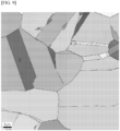
- FIG. 2 shows a microstructure of an embodiment in which a non-annealed band is not observed and bending cracks do not occur after the 180° bending test.
- Comparative Examples 6 to 8 exhibited low pitting potentials because the Mn contents were excessive due to the low Ni contents, resulting in deterioration of corrosion resistance.
- Comparative Example 2 was 25.2, which was greater than that of the present disclosure, the surface roughness was greater in accordance with the tensile strain. This may be confirmed in Table 3 and FIG. 6 .
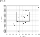
- FIG. 1 shows ranges of ⁇ values and ⁇ values of Examples 1 to 6 and Comparative Examples 1 to 8. Comparative Examples 2 to 8 did not simultaneously satisfy the ⁇ value and the S2 value. That is, both of hardness and high strength-high ductility cannot be satisfied thereby.
- FIGS. 2 and 3 are photographs showing microstructures of central portions in the thickness direction obtained by EBSD. Non-annealed bands were observed in the microstructure in a comparative example ( FIG. 3 ). On the contrary, non-annealed bands were not observed in the microstructure of an embodiment ( FIG. 2 ). In comparison, the austenitic stainless steel according to an embodiment of the present disclosure was confirmed to have ultra-fine grains without non-annealed portions in the form of band.
- FIGS. 4 and 5 show fractions (%) of martensite (red color) in cold-rolled materials of an embodiment and a comparative example when the phase fraction of the central portion in the thickness direction of the transverse direction (TD) side was analyzed by electron back scatter diffraction (EBSD) after cold rolling.
- the martensite fraction of 60% or more in the embodiment ( FIG. 4 ) may be compared with the martensite fraction less than 60% in the comparative example ( FIG. 5 ).
- FIGS. 6 and 7 show fractions (%) of misorientation angles of 15° or more in the cold-annealed materials of an embodiment and a comparative example when the central portion in the thickness direction of the transverse direction (TD) side was analyzed by electron back scatter diffraction (EBSD).
- the fraction (%) of misorientation angles ⁇ 15° of 95% or more in the embodiment ( FIG. 6 ) may be compared with the fraction (%) of misorientation angles ⁇ 15° of 95% in the comparative example ( FIG. 7 ).
- the misorientation angle less than 15° corresponds to red color.
- FIGS. 8 and 9 are photographs showing average grain sizes of central portions in the thickness direction of the transverse direction (TD) side in a steel material with a thickness of 0.4 to 2.0 mm according to an embodiment and a comparative example. It was confirmed that the average grain size of the comparative example ( FIG. 9 ) was greater than that of the embodiment ( FIG. 8 ).
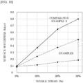
- FIG. 10 shows surface roughnesses Ra ( ⁇ m) values of Comparative Example 2 having a greater average grain size of a central portion on the surface of the manufactured steel material than that of the embodiment after conducting a uniaxial tensile test at different tensile strains with a crosshead speed of 10 to 20 mm/min. It was confirmed that the surface roughness Ra values at the tensile strains did not satisfy the range of the present disclosure when the average grain size is out of the range of the present disclosure.
- FIG. 11 is a photograph showing shapes of surface roughness Ra ( ⁇ m) after a uniaxial tensile test was performed at different tensile strains with a crosshead speed of 10 to 20 mm/min. Units of the x -axis and y-axis were mm and the unit of the height corresponds to ⁇ m. Because the height increases as the strains increases, it was confirmed surface roughness was high. On the contrary, it may be confirmed that the embodiment exhibited lower surface roughness than that of comparative example although strains are applied thereto.
- FIG. 12 is a photograph showing earring heights after a drawing process (punch size of ⁇ 50 mm and disc size of ⁇ 100 mm).
- the average earring height is an average of a value obtained by subtracting a sum of minimum heights h of earrings from a sum of maximum heights H of earrings from the bottom after a drawing process. It was confirmed that the average earring height of the embodiment was smaller than that of the comparative example.
- an ultra-fine grain 300 series stainless steel satisfying both high strength and high ductility may be provided.
- an austenitic stainless steel without surface cracks in bent portions and having excellent surface roughness properties may be provided. Therefore, industrial applicability of the present disclosure is apparent from the above description.
Landscapes
- Chemical & Material Sciences (AREA)
- Engineering & Computer Science (AREA)
- Mechanical Engineering (AREA)
- Materials Engineering (AREA)
- Metallurgy (AREA)
- Organic Chemistry (AREA)
- Physics & Mathematics (AREA)
- Thermal Sciences (AREA)
- Crystallography & Structural Chemistry (AREA)
- Heat Treatment Of Sheet Steel (AREA)
Abstract
Description
- The present disclosure relates to an austenitic stainless steel having excellent hardness, high strength-high ductility, drawability, bending properties, and improved surface properties.
- In general, austenitic stainless steels have been applied for various uses to manufacture parts for transportation and construction due to excellent formability, work hardenability, and weldability. However, since 304 series stainless steels or 301 series stainless steels have low yield strengths of 200 to 350 MPa, there are limits to apply these stainless steels to structural materials. Thus, a skin pass rolling process is generally conducted to increase yield strength of 300 series stainless steels for common use. However, the skin pass rolling process may cause problems of increasing manufacturing costs and significantly deteriorating elongation of materials.
- Patent Document 0001 discloses a method for manufacturing a 300 series stainless steel for a laser metal mask for photoetching having a small curvature even after half etching, by performing stress relief (SR) heat treatment twice after skin pass rolling a cold-rolled, annealed material. However, Patent Document 0001 relates to a manufacturing method to control etchability and a curvature after etching, but does not include technical content regarding structural parts with a thickness of 0.4 to 2.0 mm. Because an austenitic stability parameter (ASP) calculated by Md30(°C)=497-462*([C]+[N])-9.2*[Si]-8.1*[Mn]-13.7*[Cr]-20*[Ni]+[Cu]-18.7*[Mo] is in the range of 30 to 50, strain-induced martensite transformation occurs too quickly during forming, for example, during a tensile test, resulting in deterioration of elongation.
- Patent Document 0002 discloses a method of performing heat treatment for a long time over 48 hours in a temperature range of 600 to 700°C to adjust an average grain size to 10 µm or less. However, according to the method disclosed in
Patent Document 2, productivity decreases in the case of being implemented in a real production line, and manufacturing costs increase. -
- Patent Document 0001:
International Patent Application Publication No. 2016-043125 A1 (Date of Publication: March 14, 2016 ) - Patent Document 0002:
Japanese Patent Application Laid-Open No. 2020-050940 A (Date of Publication: April 2, 2020 - The present disclosure has been proposed to solve the above-described problems, and provided is an austenitic stainless steel having excellent surface roughness properties without surface cracks at bent portions by suggesting an ultra-fine grain manufacturing technique realizing hardness, high strength-high ductility, drawability, bending properties, and sound surface properties of bent portions.
- An austenitic stainless steel according to an embodiment of the present disclosure includes, in percent by weight (wt%), 0.04 to 0.07% of C, 0.3 to 0.6% of Si, 0.5 to 1.5% of Mn, 0.1 to 0.4% of Cu, 0.05 to 0.2% of Mo, 8.0 to 9.0% of Ni, 18.0 to 19.0% of Cr, 0.02 to 0.05% of N, and the remainder of Fe and inevitable impurities,
wherein a Σ value represented by Equation (1) below is at least 180 but not more than 240:Σ = 105 + 146d-1/2 + 7.36SPM_El + 102[C] + 154[N] + 51.8[Si] + 1.4[Mo] - 17.7[Cu]
(in Equation (1), [C], [N], [Si], [Mo], and [Cu] represent weight percentages (wt%) of respective elements, d represents an average grain size (µm), and SPM_El represents a difference in elongation (%) before and after skin pass milling). - In addition, in the austenitic stainless steel, an Ω value represented by Equation (2) below may be 2500 or more:

(in Equation (2), [Ni], [Cr], [Cu], and [Mn] represent weight percentages (wt%) of respective elements, YS represents yield strength (MPa), and El represents elongation (%)). - In addition, in the austenitic stainless steel, an austenitic stability parameter (ASP) value represented by Equation (3) below may be from -5 to 12:
ASP = 551 - 462*([C]+[N]) - 9.2*[Si] - 8.1*[Mn] - 13.7*[Cr] - 29*([Ni]+[Cu])-18.5*[Mo]
(in Equation (3), [C], [N], [Si], [Mn], [Cr], [Ni], [Cu], and [Mo] represent weight percentages (wt%) of respective elements). - In addition, in the austenitic stainless steel, a Π value represented by Equation (4) below may be 6000 or more:
Π = 100*FCRR (final cold rolling ratio, %)+ 100*ASP (austenitic stability parameter) + CAT (cold annealing temperature, °C)
(in Equation (4), FCRR is a reduction ratio by cold rolling before final cold annealing, ASP is a value obtained by Equation (3), and CAT is a value defined by a temperature of a final cold-annealed steel material). - In addition, in the austenitic stainless steel, an average grain size d at a central portion in the thickness direction of a transverse direction (TD) side may be at least 3 but not more than 10 µm assuming that a total thickness of a steel material is t.
- In addition, in the austenitic stainless steel, the t may be from 0.4 to 2.0 mm.
- In addition, in the austenitic stainless steel, a martensite fraction(%) of a cold-rolled material may be 60% or more when the central portion in the thickness direction of the transverse direction (TD) side is analyzed by electron back scatter diffraction (EBSD).
- In addition, in the austenitic stainless steel, a fraction (%) of misorientation angles 15° or more may be 95% or more when the central portion in the thickness direction of the transverse direction (TD) side is analyzed by electron back scatter diffraction (EBSD).
- In addition, in the austenitic stainless steel, a pitting potential measured by immersing the austenitic stainless steel in a 3.5% NaCl solution at 30°C may be 250 mV or more.
- In addition, in the austenitic stainless steel, a surface roughness Ra when stretched by 30% may be 0.50 µm or less, a surface roughness when stretched by 20% Ra may be 0.36 µm or less, and a surface roughness Ra when stretched by 10% may be 0.25 µm or less.
- In addition, in the austenitic stainless steel, the austenitic stainless steel may have an aging crack limit drawing ratio of 2.0 or more.
- In addition, in the austenitic stainless steel, an average earring height may be 2.2 mm or less after a drawing process of the stainless steel.
- In addition, in the austenitic stainless steel, surface cracks do not occur in a bent portion after a 180° bending test.
- According to an embodiment of the present disclosure, a ultra-fine grain 300 series stainless steel having excellent hardness may be provided.
- According to an embodiment of the present disclosure, a ultra-fine grain 300 series stainless steel satisfying both high strength and high ductility may be provided.
- According to an embodiment of the present disclosure, an austenitic stainless steel having excellent surface roughness without surface cracks at bent portions may be provided by a ultra-fine grain manufacturing technique realizing bending formability and sound surface properties of bent portions.
-
-
FIG. 1 is a graph showing Σ and S2 values of embodiments and comparative examples. -
FIG. 2 is a photograph showing a microstructure of an embodiment satisfying a Π value of 6000 or more. -
FIG. 3 is a photograph showing non-annealed bands in a microstructure of Comparative Example 1 in which the Π value is less than 6000. -
FIG. 4 is a photograph showing cold-rolled materials according to embodiments in which fractions (%) of martensite (red color) are 91.5% and 73.5% when phase fractions of a central portion in the thickness direction of the transverse direction (TD) side is analyzed by electron back scatter diffraction (EBSD). -
FIG. 5 is a photograph showing a cold-rolled material according to a comparative example in which a fraction (%) of martensite (red color) is 48.5% when a phase fraction of a central portion in the thickness direction of the transverse direction (TD) side is analyzed by electron back scatter diffraction (EBSD). -
FIG. 6 is a photograph showing cold-annealed materials according to an embodiment in which fractions (%) of misorientation angles of 15° or more are 96% and 96.5% when a central portion in the thickness direction of the transverse direction (TD) side is analyzed by electron back scatter diffraction (EBSD). -
FIG. 7 is a photograph showing a cold-annealed material according to a comparative example in which a fraction (%) of misorientation angles of 15° or more is 92.9% when a central portion in the thickness direction of the transverse direction (TD) side is analyzed by electron back scatter diffraction (EBSD). Here, a misorientation angle less than 15° corresponds to red color. -
FIG. 8 is a photograph showing an average grain size at a central portion in the thickness direction of the transverse direction (TD) side of a steel material with a thickness of 0.4 to 2.0 mm manufactured according to an embodiment. -
FIG. 9 is a photograph showing an average grain size at a central portion in the thickness direction of the transverse direction (TD) side of a steel material with a thickness of 0.4 to 2.0 mm manufactured according to a comparative example. -
FIG. 10 shows surface roughness Ra (µm) values of an embodiment and Comparative Example 2 according to tensile strain. -
FIG. 11 is a photograph showing shapes of surface roughness Ra (µm) according to tensile strain in an embodiment and a comparative example. -
FIG. 12 is a photograph showing earring heights after a drawing process in an embodiment and a comparative example. - An austenitic stainless steel according to an embodiment of the present disclosure includes, in percent by weight (wt%), 0.04 to 0.07% of C, 0.3 to 0.6% of Si, 0.5 to 1.5% of Mn, 0.1 to 0.4% of Cu, 0.05 to 0.2% of Mo, 8.0 to 9.0% of Ni, 18.0 to 19.0% of Cr, 0.02 to 0.05% of N, and the remainder of Fe and inevitable impurities,
wherein a Σ value represented by Equation (1) below may be at least 180 but not more than 240.Σ = 105 + 146d-1/2 + 7.36SPM_El + 102[C] + 154[N] + 51.8[Si] + 1.4[Mo] - 17.7[Cu] - In Equation (1) above, [C], [N], [Si], [Mo], and [Cu] represent weight percentages (wt%) of respective elements, d represents an average grain size (µm), and SPM_El represents a difference in elongation (%) before and after skin pass milling.
- Hereinafter, embodiments of the present disclosure will be described in detail with reference to the accompanying drawings. The embodiments of the present disclosure may, however, be embodied in many different forms and should not be construed as being limited to the embodiments set forth herein. Rather, these embodiments are provided so that this disclosure will be thorough and complete, and will fully convey the concept of the invention to those skilled in the art.
- The terms used herein are merely used to describe particular embodiments. An expression used in the singular encompasses the expression of the plural, unless otherwise indicated. Throughout the specification, the terms such as "including" or "having" are intended to indicate the existence of features, operations, functions, components, or combinations thereof disclosed in the specification, and are not intended to preclude the possibility that one or more other features, operations, functions, components, or combinations thereof may exist or may be added.
- Meanwhile, unless otherwise defined, all terms used herein have the same meaning as commonly understood by one of ordinary skill in the art to which this disclosure belongs. Thus, these terms should not be interpreted in an idealized or overly formal sense unless expressly so defined herein. As used herein, the singular forms are intended to include the plural forms as well, unless the context clearly indicates otherwise.
- The terms "about", "substantially", etc. used throughout the specification means that when a natural manufacturing and a substance allowable error are suggested, such an allowable error corresponds the value or is similar to the value, and such values are intended for the sake of clear understanding of the present invention or to prevent an unconscious infringer from illegally using the disclosure of the present invention.
- An austenitic stainless steel according to an embodiment of the present disclosure may include, in percent by weight (wt%), 0.04 to 0.07% of C, 0.3 to 0.6% of Si, 0.5 to 1.5% of Mn, 0.1 to 0.4% of Cu, 0.05 to 0.2% of Mo, 8.0 to 9.0% of Ni, 18.0 to 19.0% of Cr, 0.02 to 0.05% of N, and the remainder of Fe and inevitable impurities.
- Hereinafter, reasons for numerical limitations on the contents of alloying elements in the embodiment of the present disclosure will be described.
- The content of carbon (C) may be from 0.04% to 0.07%.
- C is an austenite phase-stabilizing element. In consideration thereof, C may be added in an amount of 0.04% or more. However, since an excess of C causes a problem of deteriorating grain boundary corrosion resistance by forming a chromium carbide during low-temperature annealing. In consideration thereof, the upper limit of the C content may be controlled to 0.07%.
- The content of silicon (Si) may be from 0.3 to 0.6%.
- Si is an element added as a deoxidizer during a steel-making process and has an effect on improving corrosion resistance of a steel by forming an Si oxide in a passivated layer in the case of performing a bright annealing process. In consideration thereof, Si may be added in an amount of 0.3 wt% or more. However, an excess of Si may cause a problem of deteriorating ductility. In consideration thereof, the upper limit of the Si content may be controlled to 0.6%.
- The content of manganese (Mn) may be from 0.5 to 1.5%.
- Mn is an austenite phase-stabilizing element. In consideration thereof, Mn may be added in an amount of 0.5 wt% or more. However, an excess of Mn may cause a problem of deteriorating corrosion resistance. In consideration thereof, the upper limit of the Mn content may be controlled to 1.5%.
- The content of nickel (Ni) may be from 8.0 to 9.0%.
- Ni is an austenite phase-stabilizing element and has an effect on softening a steel material. In consideration thereof, Ni may be added in an amount of 8.0 wt% or more. However, an excess of Ni may cause a problem of increasing costs. In consideration thereof, the upper limit of the Ni content may be controlled to 9.0 wt%.
- The content of chromium (Cr) may be from 18.0 to 19.0%.
- Cr is a major element for improving corrosion resistance of a stainless steel. In consideration thereof, Cr may be added in an amount of 18.0 wt% or more. However, an excess of Cr causes problems of hardening of a steel material and inhibiting strain-induced martensite transformation during cold rolling. In consideration thereof, the upper limit of the Cr content may be controlled to 19.0 wt%.
- The content of copper (Cu) may be from 0.1 to 0.4%.
- Cu is an austenite phase-stabilizing element. In consideration thereof, Cu may be added in an amount of 0.1% or more. However, an excess of Cu may cause problems of deteriorating corrosion resistance of a steel material and increasing costs. In consideration thereof, the upper limit of the Cu content may be controlled to 0.4%.
- The content of nitrogen (N) may be from 0.02 to 0.05%.
- N is an austenite phase-stabilizing element and improves strength of a steel material. In consideration thereof, N may be added in an amount of 0.02% or more. However, an excess of N causes problems of hardening a steel material and deteriorating hot workability. In consideration thereof, the upper limit of the N content may be controlled to 0.05 wt%.
- The content of molybdenum (Mo) may be from 0.05 to 0.2%.
- Mo has an effect on improving corrosion resistance and workability. In consideration thereof, Mo may be added in an amount of 0.05% or more. However, an excess of Mo may cause a problem of increasing costs. In consideration thereof, the upper limit of the Mo content may be controlled to 0.2 wt%.
- The remaining component of the composition of the present disclosure is iron (Fe). However, the composition may include unintended impurities inevitably incorporated from raw materials or surrounding environments, and thus addition of other alloying elements is not excluded. These impurities are known to any person skilled in the art of manufacturing and details thereof are not specifically mentioned in the present disclosure.
- As well as limiting the contents of the alloying elements of the stainless steel according to the present disclosure as described above, the relationships therebetween may further be limited as follows.
- In an embodiment of the present disclosure, a Σ value represented by Equation (1) below may be at least 180 but not more than 240.
Σ = 105 + 146d-1/2 + 7.36SPM_El + 102[C] + 154[N] + 51.8[Si] + 1.4[Mo] - 17.7[Cu] - Σ is an indicator representing hardness of a material, and a higher Σ value indicates a greater hardness.
- In Equation (1) above, [C], [N], [Si], [Mo], and [Cu] represent weight percentages (wt%) of respective elements, d represents an average grain size (µm), and SPM_El represents a difference in elongation (%) before and after skin pass milling.
- The SPM_El according to an embodiment of the present disclosure may be from 0.01 to 1.2.
- The skin pass milling may be performed to improve gloss of a steel material and to ensure the shape of a coil.
- In an embodiment of the present disclosure, an Ω value represented by Equation (2) below may be 2500 or more.

- Ω is an indicator representing high strength and high ductility, and a higher Ω value indicates a higher product of strength and ductility.
- In Equation (2) above, [Ni], [Cr], [Cu], and [Mn] represent weight percentages (wt%) of respective elements, YS represents yield strength (MPa), and El represents elongation (%).
- The YS and El values refer to values obtained after a tensile test is conducted on a sample according to JIS13B standards at room temperature in a crosshead range of 10 mm/min to 20 mm/min.
- In an embodiment of the present disclosure, an austenitic stability parameter (ASP) value represented by Equation (3) below may be from -5 to 12.
ASP = 551 - 462*([C]+[N]) - 9.2*[Si] - 8.1*[Mn] - 13.7*[Cr] - 29*([Ni]+[Cu])-18.5*[Mo] - In Equation (3) above, [C], [N], [Si], [Mn], [Cr], [Ni], [Cu], and [Mo] represent weight percentages (wt%) of respective elements.
- If the ASP value is out of the range of -5 to 12, transformation of a material excessively occurs, failing to satisfy a desired elongation in the present disclosure.
- In an embodiment of the present disclosure, a Π value represented by Equation (4) below may be 6000 or more.
Π = 100*FCRR (final cold rolling ratio, %)+ 100*ASP (austenitic stability parameter) + CAT (cold annealing temperature, °C) - Π is an indicator that represents the degree of completion of recrystallization, and a higher Π value indicates a higher degree of recrystallization.
- In Equation (4) above, FCRR refers to a reduction ratio by cold rolling before final cold annealing, ASP refers to a value obtained by Equation (3), and CAT refers to a value defined by a temperature of a final cold-rolled, annealed steel material.
- The average grain size d according to an embodiment of the present disclosure may be at least 3 but not more than 10 µm.
- The average grain size refers to an average grain size at a central portion in the thickness direction of the transverse direction (TD) side assuming that a total thickness of a steel material is t, and the average refers to an average of values measured at 5 random positions, and the central portion refers to a position located from 1/4t to 3/4t assuming that the total thickness of the steel material is t.
- The total thickness t according to an embodiment of the present disclosure may be from 0.4 to 2.0 mm. Materials with a thickness of 0.4 to 2.0 mm are widely used for parts of kitchen and building materials, and stainless steel having excellent hardness, high strength, and high ductility may be provided within the thickness range described above according to the present disclosure.
- In an embodiment of the present disclosure, when the central portion in the thickness direction of the transverse direction (TD) side is analyzed by electron back scatter diffraction (EBSD), a martensite phase fraction (%) of a cold-rolled material may be 60% or more, and a fraction (%) of misorientation angles of 15° or more may be 95% or more after cold annealing.
- A misorientation angle is 15° or more indicates that recrystallization occurs after cold annealing, and a misorientation angle less than 15° indicates that recrystallization does not occur due to a small difference in orientations.
- The average grain size d, the martensite fraction (%) of the cold-rolled material, and the fraction (%) of misorientation angles of 15° or more after cold annealing of the present disclosure were measured by analyzing orientations of the central portion in the thickness direction by electron back scatter diffraction (EBSD) with Model No. e-Flash FS.
- Pitting potential refers to a critical potential causing corrosion in the form of holes in a passivated metal material. The austenitic stainless steel according to an embodiment of the present disclosure may have a pitting potential of 250 mV or more when measured by immersing the austenitic stainless steel in a NaCl solution and applying a potential causing pitting thereto. In this regard, a temperature of the NaCl solution may be 30°C and a concentration thereof may be 3.5%.
- The austenitic stainless steel according to an embodiment of the present disclosure may have a surface roughness Ra of 0.50 µm or less when stretched by 30%, a surface roughness Ra of 0.36 µm or less when stretched by 20%, and a surface roughness Ra of 0.25 µm when stretched by 10%.
- In the case of performing a drawing process with a punch size of Φ50 mm and a disc size of Φ100 mm according to an embodiment of the present disclosure, an aging crack limit drawing ratio may be 2.0 or more. In addition, an average earring height may be 2.2 mm or less.
- The aging crack limit drawing ratio, as a limit drawing ratio not causing aging cracks, refers to a ratio of maximum diameter of a material to punch diameter during a drawing process.
- The average earring height refers to an average of a value obtained by subtracting a sum of minimum heights h of earrings from a sum of maximum heights H of earrings from the bottom after the drawing process.
- Surface cracks may not occur at bent portions after a 180° bending test according to an embodiment of the present disclosure.
- Hereinafter, a method of manufacturing an austenitic stainless steel according to an embodiment of the present disclosure will be described in more detail.
- A method of manufacturing an austenitic stainless steel according to an embodiment of the present disclosure may include: manufacturing a slab including, in percent by weight (wt%), 0.04 to 0.07% of C, 0.3 to 0.6% of Si, 0.5 to 1.5% of Mn, 0.1 to 0.4% of Cu, 0.05 to 0.2% of Mo, 8.0 to 9.0% of Ni, 18.0 to 19.0% of Cr, 0.02 to 0.05% of N, and the remainder of Fe and inevitable impurities;
- hot rolling and hot annealing the slab into a hot-rolled steel sheet; and
- cold rolling and cold annealing the hot-rolled steel sheet into a cold-rolled steel sheet.
- Reasons for limitations on the composition of alloying elements are as described above, and hereinafter, processes of the manufacturing method will be described in more detail.
- The hot annealing may be performed at a temperature of 1000 to 1150°C.
- When a hot annealing temperature is below 1000°C, elongation may deteriorate due to a high fraction of remaining martensite. On the contrary, when the hot annealing temperature exceeds 1150°C, strength may decrease due to coarsening of crystal grains. In consideration thereof, the hot annealing is performed at a temperature of 1000 to 1150°C.
- A reduction ratio of the cold rolling may be 60% or more.
- When the reduction ratio is less than 60%, the martensite fraction of the cold-rolled material decreases and the fraction of retained austenite phase increases due to a too low amount of TRIP transformation. As the amount of the strain-induced martensite decreases, the ratio of the reverted austenite phase during the subsequent low-temperature annealing decreases, and the fraction of retained austenite phase without being transformed into martensite increases, making it difficult to obtain ultra-fine grains.
- The cold annealing may be performed at a temperature of 800 to 950°C.
- When the temperature of the cold annealing is below 800°C, recrystallization does not sufficiently occur, resulting in a decrease in elongation. On the contrary, when the temperature of the cold annealing exceeds 950°C, grains coarsen making formation of ultra-fine grains with a size of 3 to 10 µm difficult, so that there may be problems such as surface cracks occurring at bent portions of the austenitic stainless steel and worsening of surface roughness. In consideration thereof, the cold annealing is performed at a temperature of 800 to 950°C.
- In addition, the manufacturing method may be a method of manufacturing an austenitic stainless steel including skin pass milling the cold-rolled steel sheet.
- The SPM_El, as a difference in elongation (%) before and after skin pass milling, may be from 0.01 to 1.2.
- Hereinafter, the present disclosure will be described in more detail through following examples. However, it is necessary to note that the following examples are only intended to illustrate the present disclosure in more detail and are not intended to limit the scope of the present disclosure. This is because the scope of the present disclosure is determined by matters described in the claims and able to be reasonably inferred therefrom.
- Slabs having the compositions of alloying elements shown in Table 1 below were hot-rolled and hot-annealed at a temperature of 1000 to 1150°C, and then cold-rolled at room temperature with a reduction ratio of 60% or more. Subsequently, the resultant was cold-annealed at a temperature of 800 to 950°C into a cold annealed material.
[Table 1] Category C Si Mn Cr Ni Cu Mo N Example 1 0.05 0.3 1.1 18.1 8.1 0.25 0.1 0.03 Example 2 0.05 0.3 1.1 18.1 8.1 0.25 0.1 0.03 Example 3 0.06 0.3 1.1 18.1 8.1 0.25 0.1 0.04 Example 4 0.06 0.5 1.1 18.1 8.1 0.22 0.1 0.05 Example 5 0.04 0.4 0.8 18.1 8.1 0.24 0.1 0.05 Example 6 0.04 0.3 0.8 18.1 8.2 0.35 0.1 0.05 Comparative Example 1 0.05 0.2 1.1 18.1 8.05 0.28 0.1 0.04 Comparative Example 2 0.06 0.5 1.1 18.1 8.1 0.22 0.1 0.05 Comparative Example 3 0.02 0.3 1.4 18.5 8.7 0.35 0.1 0.04 Comparative Example 4 0.05 0.4 1.1 19.1 9.5 0.35 0.1 0.04 Comparative Example 5 0.10 0.3 1.1 17.1 6.8 0.25 0.1 0.03 Comparative Example 6 0.02 0.3 2.5 17.2 2.5 0.25 0.1 0.12 Comparative Example 7 0.05 0.2 5.5 18.1 3.5 1.50 0.1 0.04 Comparative Example 8 0.10 0.2 6.5 18.1 2.5 0.25 0.1 0.20 - Table 2 below shows output values of Equations (1) to (4) based on the contents of the elements of Table 1, skin pass mill elongations (SPM El, %), final cold rolling ratios (FCRR, %), cold annealing temperatures (CAT, °C), and YS(MPa)*El (%) values.
[Table 2] Category SPM_El (%) FCRR (%) CAT (°C) YS(MPa)* E1 (%) Equation (1): ∑ Equation (2): Ω Equation (3): ASP Equation (4): Π Example 1 0.5 72 950 16464 184 2689 10.4 9190 Example 2 0.7 65 850 18576 196 4801 10.4 8390 Example 3 0.7 82 800 18758 215 4983 1.2 9116 Example 4 1.0 67 900 17889 206 4129 -4.4 7157 Example 5 1.0 75 820 19228 210 5608 7.6 9078 Example 6 0.4 67 925 18040 186 4315 2.4 7866 Comparative Example 1 0.5 35 750 18336 204 4571 7.3 4978 Comparative Example 2 0.5 82 1100 14824 174 1064 -4.4 8857 Comparative Example 3 0.5 62 980 16065 171 1590 -8.6 6323 Comparative Example 4 0.4 70 950 16203 175 1178 -52.3 2716 Comparative Example 5 0.4 68 800 14331 203 1706 38.7 11470 Comparative Example 6 0.4 70 800 13568 209 2343 146.1 22407 Comparative Example 7 0.5 68 800 13003 187 -1297 68.2 14421 Comparative Example 8 0.5 64 780 22000 248 8325 28.3 10014 - The YS and El values refer to values obtained after conducting a tensile test on the manufactured samples according to the JIS13B standards at room temperature within a crosshead range of 10 mm/min to 20mm/min.
- The cold annealed material was manufactured into a sample having a thickness of 0.4 to 2.0 mm. Then, average grain sizes d at central portions in the thickness direction of the samples, pitting potentials (mV), occurrence of surface cracks in bent portions after a 180° bending test (radius of curvature R of the bent portion is the same as the thickness of the material), and surface roughnesses at different tensile strains in a uniaxial tensile test were measured, and results are shown in Table 3 below.
[Table 3] Category d (µm) Pitting potential (mV) Surface roughness at 10% tensile strain (Ra, um) Surface roughness at 20% tensile strain (Ra, um) Surface roughness at 30% tensile strain (Ra, um) Bending cracks (Y/N) Example 1 7.2 341 0.22 0.36 0.49 N Example 2 5.1 283 0.18 0.28 0.39 N Example 3 3.2 254 0.15 0.17 0.19 N Example 4 6.4 313 0.20 0.38 0.45 N Example 5 4.5 289 0.17 0.24 0.32 N Example 6 6.7 305 0.21 0.35 0.48 N Comparative Example 1 3.5 240 0.15 0.18 0.25 Y Comparative Example 2 25.2 312 0.38 0.66 0.80 N Comparative Example 3 10.5 345 0.28 0.45 0.55 N Comparative Example 4 12.5 322 0.32 0.49 0.61 N Comparative Example 5 4.5 255 0.15 0.24 0.32 Y Comparative Example 6 4.5 295 0.15 0.25 0.32 Y Comparative Example 7 3.1 150 0.14 0.18 0.25 Y Comparative Example 8 2.5 190 0.11 0.16 0.11 Y - The average grain size d of the central portion in the thickness direction refers to an average grain size d of the central portion in the thickness direction of the transverse direction (TD) side of each sample having a thickness of 0.4 to 2.0 mm.
- The average grain size d of the present disclosure was measured by analyzing orientations at the central portion in the thickness direction by electron back scatter diffraction (EBSD) with Model No. e-Flash FS.
- The pitting potential refers to a potential at which pitting occurs measured by immersing each sample in a 3.5% NaCl solution at 30°C, and applying potentials thereto.
- The tensile strain refers to a value measured by a uniaxial tensile test conducted on each sample according to JIS13B standards with a crosshead speed of 10 to 20 mm/min.
- Occurrence of bending cracks was measured by a 180° bending test conducted by adjusting the radius of curvature R of the bent portion to be equal to the thickness of the material and bending once.
- Table 4 below shows average earring heights according to an embodiment of the present disclosure.
[Table 4] Earring 1Earring 2Earring 3Earring 4Average earring height Comparative Example maximum height (H) 43.54 42.87 43.67 44.00 2.87 Comparative Example minimum height (h) 40.96 39.87 40.82 40.96 Example maximum height (H) 41.59 42.40 42.87 42.62 1.88 Example minimum height (h) 40.05 39.86 40.96 41.07 - The average earring height refers to an average of a value obtained by subtracting a sum of minimum heights h of earrings from a sum of maximum heights H of earrings from the bottom after a drawing process. H refers to a maximum height, h refers to a minimum height, and
Earrings 1 toEarring 4 are random orders of the earrings. - LDR value and average earring height refer to aging crack limit drawing ratio and average earring height in the case of conducting a drawing process with a punch size of Φ50 mm and a disc size of Φ100 mm, respectively.
- Referring to Tables 1 and 2, all of Examples 1 to 6 satisfied the Σ value (Equation (1)) range of at least -180 but not more than 240 and the S2 value (Equation (2)) range of 2500 or more, and may realize excellent hardness, high strength, and high ductility.
- Referring to Tables 1 to 3, all of Examples 1 to 6 satisfied the ASP value (Equation (3)) range of -5 to 12 and the Π value (Equation (4)) of 6000 or more, so that surface cracks did not occur after the 180° bending test.
- Referring to Table 3, in the case of Examples 1 to 6, the average grain sizes d of the central portions in the thickness direction satisfied the range of at least 3 but not more than 10 µm in the material having a thickness of 0.4 to 2.0 mm, and after the uniaxial tensile test, the surface roughnesses Ra when stretched by 30% were not more than 0.50 µm, the surface roughnesses Ra when stretched by 20% were not more than 0.36 µm, and the surface roughnesses Ra when stretched by 10% were not more than 0.25 µm. In addition, the pitting potentials satisfied the range of 250 mV or more.
- On the contrary, the Σ values of Comparative Examples 2 to 4 were less than 180 failing to satisfy the hardness of the present disclosure. This may be confirmed in Table 2.
- In addition, the S2 values of Comparative Examples 2 to 7 were less than 2500 failing to satisfy the high strength-high ductility of the present disclosure. This may be confirmed in Table 2.
- In addition, the ASP values of Comparative Examples 3 to 8 were out of the ASP range disclosed in the present disclosure. According to Comparative Examples 5 to 8 in which the ASP values exceeded 12, elongation was low due to too fast transformation rates. According to Comparative Examples 2 to 4 in which the ASP values were less than -5, ultra-fine grains could not be obtained due to high fractions of the remaining austenite phase. This may be confirmed in Tables 2 and 3.
- In addition, non-annealed bands are shown in Comparative Example 1 because the Π value is smaller than 6000, and bending cracks occur after the 180° bending test in the steel material including the same. This may be confirmed in Tables 2 and 3 and
FIG. 3 . On the contrary,FIG. 2 shows a microstructure of an embodiment in which a non-annealed band is not observed and bending cracks do not occur after the 180° bending test. - In addition, Comparative Examples 6 to 8 exhibited low pitting potentials because the Mn contents were excessive due to the low Ni contents, resulting in deterioration of corrosion resistance.
- Also, because the average grain size d of Comparative Example 2 was 25.2, which was greater than that of the present disclosure, the surface roughness was greater in accordance with the tensile strain. This may be confirmed in Table 3 and
FIG. 6 . -
FIG. 1 shows ranges of Σ values and Ω values of Examples 1 to 6 and Comparative Examples 1 to 8. Comparative Examples 2 to 8 did not simultaneously satisfy the Σ value and the S2 value. That is, both of hardness and high strength-high ductility cannot be satisfied thereby. -
FIGS. 2 and3 are photographs showing microstructures of central portions in the thickness direction obtained by EBSD. Non-annealed bands were observed in the microstructure in a comparative example (FIG. 3 ). On the contrary, non-annealed bands were not observed in the microstructure of an embodiment (FIG. 2 ). In comparison, the austenitic stainless steel according to an embodiment of the present disclosure was confirmed to have ultra-fine grains without non-annealed portions in the form of band. -
FIGS. 4 and5 show fractions (%) of martensite (red color) in cold-rolled materials of an embodiment and a comparative example when the phase fraction of the central portion in the thickness direction of the transverse direction (TD) side was analyzed by electron back scatter diffraction (EBSD) after cold rolling. The martensite fraction of 60% or more in the embodiment (FIG. 4 ) may be compared with the martensite fraction less than 60% in the comparative example (FIG. 5 ). -
FIGS. 6 and7 show fractions (%) of misorientation angles of 15° or more in the cold-annealed materials of an embodiment and a comparative example when the central portion in the thickness direction of the transverse direction (TD) side was analyzed by electron back scatter diffraction (EBSD). The fraction (%) of misorientation angles ≥ 15° of 95% or more in the embodiment (FIG. 6 ) may be compared with the fraction (%) of misorientation angles < 15° of 95% in the comparative example (FIG. 7 ). The misorientation angle less than 15° corresponds to red color. -
FIGS. 8 and9 are photographs showing average grain sizes of central portions in the thickness direction of the transverse direction (TD) side in a steel material with a thickness of 0.4 to 2.0 mm according to an embodiment and a comparative example. It was confirmed that the average grain size of the comparative example (FIG. 9 ) was greater than that of the embodiment (FIG. 8 ). -
FIG. 10 shows surface roughnesses Ra (µm) values of Comparative Example 2 having a greater average grain size of a central portion on the surface of the manufactured steel material than that of the embodiment after conducting a uniaxial tensile test at different tensile strains with a crosshead speed of 10 to 20 mm/min. It was confirmed that the surface roughness Ra values at the tensile strains did not satisfy the range of the present disclosure when the average grain size is out of the range of the present disclosure. -
FIG. 11 is a photograph showing shapes of surface roughness Ra (µm) after a uniaxial tensile test was performed at different tensile strains with a crosshead speed of 10 to 20 mm/min. Units of the x -axis and y-axis were mm and the unit of the height corresponds to µm. Because the height increases as the strains increases, it was confirmed surface roughness was high. On the contrary, it may be confirmed that the embodiment exhibited lower surface roughness than that of comparative example although strains are applied thereto. -
FIG. 12 is a photograph showing earring heights after a drawing process (punch size of Φ50 mm and disc size of Φ100 mm). The average earring height is an average of a value obtained by subtracting a sum of minimum heights h of earrings from a sum of maximum heights H of earrings from the bottom after a drawing process. It was confirmed that the average earring height of the embodiment was smaller than that of the comparative example. - While the present disclosure has been particularly described with reference to exemplary embodiments, it should be understood by those of skilled in the art that the scope of the present disclosure is not limited thereby and various changes in form and details may be made without departing from the spirit and scope of the present disclosure.
- According to the present disclosure, an ultra-fine grain 300 series stainless steel satisfying both high strength and high ductility may be provided. In addition, by the ultra-fine grain manufacturing technique realizing bending formability and sound surface properties of bent portions, an austenitic stainless steel without surface cracks in bent portions and having excellent surface roughness properties may be provided. Therefore, industrial applicability of the present disclosure is apparent from the above description.
Claims (13)
- An austenitic stainless steel including, in percent by weight (wt%), 0.04 to 0.07% of C, 0.3 to 0.6% of Si, 0.5 to 1.5% of Mn, 0.1 to 0.4% of Cu, 0.05 to 0.2% of Mo, 8.0 to 9.0% of Ni, 18.0 to 19.0% of Cr, 0.02 to 0.05% of N, and the remainder of Fe and inevitable impurities,
wherein a Σ value represented by Equation (1) below is at least 180 but not more than 240:Σ = 105 + 146d-1/2 + 7.36SPM_El + 102[C] + 154[N] + 51.8[Si] + 1.4[Mo] - 17.7[Cu] - The austenitic stainless steel according to claim 1, wherein an Ω value represented by Equation (2) below is 2500 or more:

- The austenitic stainless steel according to claim 1, wherein an austenitic stability parameter (ASP) value represented by Equation (3) below is from -5 to 12:
ASP = 551 - 462*([C]+[N]) - 9.2*[Si] - 8.1*[Mn] - 13.7*[Cr] - 29*([Ni]+[Cu])-18.5*[Mo] - The austenitic stainless steel according to claim 1, wherein a Π value represented by Equation (4) below is 6000 or more:
Π = 100*FCRR (final cold rolling ratio, %)+ 100*ASP (austenitic stability parameter) + CAT (cold annealing temperature, °C) - The austenitic stainless steel according to claim 1, wherein an average grain size d at a central portion in the thickness direction of a transverse direction (TD) side is at least 3 but not more than 10 µm assuming that a total thickness of a steel material is t.
- The austenitic stainless steel according to claim 1, wherein the t is from 0.4 to 2.0 mm.
- The austenitic stainless steel according to claim 1, wherein a martensite fraction (%) at the central portion in the thickness direction of the transverse direction (TD) side is 60% or more after cold rolling.
- The austenitic stainless steel according to claim 1, wherein a fraction (%) of misorientation angles of 15° or more is 95% or more at the central portion in the thickness direction of the transverse direction (TD) side after cold annealing.
- The austenitic stainless steel according to claim 1, wherein a pitting potential measured by immersing the austenitic stainless steel in a 3.5% NaCl solution at 30°C is 250 mV or more.
- The austenitic stainless steel according to claim 1, wherein a surface roughness Ra when stretched by 30% is 0.50 µm or less, a surface roughness Ra when stretched by 20% is 0.36 µm or less, and a surface roughness Ra when stretched by 10% is 0.25 µm or less.
- The austenitic stainless steel according to claim 1, wherein the austenitic stainless steel has an aging crack limit drawing ratio of 2.0 or more.
- The austenitic stainless steel according to claim 1, wherein an average earring height is 2.2 mm or less after a drawing process of the stainless steel,
wherein the average earring height is an average of a value obtained by subtracting a sum of minimum heights h of earrings from a sum of maximum heights H of earrings from the bottom after a drawing process. - The austenitic stainless steel according to claim 1, wherein surface cracks do not occur in a bent portion after a 180° bending test.
Applications Claiming Priority (2)
| Application Number | Priority Date | Filing Date | Title |
|---|---|---|---|
| KR1020220053839A KR20230153865A (en) | 2022-04-29 | 2022-04-29 | Austenitic stainless steel |
| PCT/KR2023/003278 WO2023210959A1 (en) | 2022-04-29 | 2023-03-10 | Austenitic stainless steel |
Publications (2)
| Publication Number | Publication Date |
|---|---|
| EP4481081A1 true EP4481081A1 (en) | 2024-12-25 |
| EP4481081A4 EP4481081A4 (en) | 2026-03-25 |
Family
ID=88519201
Family Applications (1)
| Application Number | Title | Priority Date | Filing Date |
|---|---|---|---|
| EP23796609.8A Pending EP4481081A4 (en) | 2022-04-29 | 2023-03-10 | AUSTENITIC STAINLESS STEEL |
Country Status (5)
| Country | Link |
|---|---|
| EP (1) | EP4481081A4 (en) |
| JP (1) | JP2025513824A (en) |
| KR (1) | KR20230153865A (en) |
| CN (1) | CN119173648A (en) |
| WO (1) | WO2023210959A1 (en) |
Families Citing this family (1)
| Publication number | Priority date | Publication date | Assignee | Title |
|---|---|---|---|---|
| CN120888735A (en) * | 2025-09-11 | 2025-11-04 | 中南大学 | A Short-Process Preparation Method for 304 Stainless Steel Strip by Continuous Casting |
Family Cites Families (15)
| Publication number | Priority date | Publication date | Assignee | Title |
|---|---|---|---|---|
| JPH0796685B2 (en) * | 1990-03-31 | 1995-10-18 | 新日本製鐵株式会社 | Method for producing Cr-Ni series stainless steel thin plate with excellent surface quality and material |
| KR950009223B1 (en) * | 1993-08-25 | 1995-08-18 | 포항종합제철주식회사 | Austenitic stainless steel with excellent press formability, hot workability and high temperature oxidation resistance |
| JP3534886B2 (en) * | 1995-03-24 | 2004-06-07 | 日新製鋼株式会社 | Austenitic stainless steel sheet excellent in pocket wave resistance and method for producing the same |
| JP3423818B2 (en) * | 1995-04-27 | 2003-07-07 | 新日本製鐵株式会社 | Method for producing austenitic stainless steel sheet slab |
| KR101056235B1 (en) * | 2008-11-25 | 2011-08-11 | 주식회사 포스코 | Prediction of Material Properties of Austenitic Stainless Steel Cold Rolled Products |
| JP5500960B2 (en) * | 2009-12-01 | 2014-05-21 | 新日鐵住金ステンレス株式会社 | Fine grain austenitic stainless steel sheet with excellent stress corrosion cracking resistance and workability |
| JP5693030B2 (en) * | 2010-03-26 | 2015-04-01 | 日新製鋼株式会社 | Austenitic stainless steel sheet with excellent detergency and method for producing the same |
| KR20160043125A (en) | 2011-12-21 | 2016-04-20 | 인텔 코포레이션 | Semiconductor devices having three-dimensional bodies with modulated heights |
| WO2014030607A1 (en) * | 2012-08-20 | 2014-02-27 | 新日鐵住金株式会社 | Stainless steel sheet and method for producing same |
| KR101707345B1 (en) * | 2012-09-04 | 2017-02-15 | 신닛테츠스미킨 카부시키카이샤 | Stainless steel sheet for precision machining and method for producing same |
| WO2016043125A1 (en) * | 2014-09-17 | 2016-03-24 | 新日鐵住金株式会社 | Austenitic stainless steel plate |
| JP2020050940A (en) | 2018-09-28 | 2020-04-02 | 国立研究開発法人日本原子力研究開発機構 | Method for producing austenitic fine-grained stainless steel |
| CN112789362B (en) * | 2018-10-04 | 2022-08-16 | 日本制铁株式会社 | Austenitic stainless steel sheet and method for producing same |
| JP7466378B2 (en) * | 2020-05-28 | 2024-04-12 | 日鉄ステンレス株式会社 | Austenitic stainless steel sheet and method for producing same |
| KR102448735B1 (en) * | 2020-09-03 | 2022-09-30 | 주식회사 포스코 | Austenitic stainless steel and manufacturing method thereof |
-
2022
- 2022-04-29 KR KR1020220053839A patent/KR20230153865A/en active Pending
-
2023
- 2023-03-10 WO PCT/KR2023/003278 patent/WO2023210959A1/en not_active Ceased
- 2023-03-10 CN CN202380037026.0A patent/CN119173648A/en active Pending
- 2023-03-10 JP JP2024559964A patent/JP2025513824A/en active Pending
- 2023-03-10 EP EP23796609.8A patent/EP4481081A4/en active Pending
Also Published As
| Publication number | Publication date |
|---|---|
| CN119173648A (en) | 2024-12-20 |
| KR20230153865A (en) | 2023-11-07 |
| EP4481081A4 (en) | 2026-03-25 |
| JP2025513824A (en) | 2025-04-30 |
| WO2023210959A1 (en) | 2023-11-02 |
Similar Documents
| Publication | Publication Date | Title |
|---|---|---|
| EP4177369A1 (en) | Austenitic stainless steel and manufacturing method thereof | |
| EP3138934B1 (en) | Martensitic stainless si-deoxidized cold rolled and annealed steel sheet and metal gasket | |
| JP4252893B2 (en) | Duplex stainless steel strip for steel belt | |
| KR101606946B1 (en) | High-strength stainless steel material and process for production of the same | |
| WO2014157146A1 (en) | Austenitic stainless steel sheet and method for manufacturing high-strength steel material using same | |
| US20240336989A1 (en) | Austenitic stainless steel and method for manufacturing same | |
| CN116490625B (en) | Double-phase stainless steel sheet, double-phase stainless steel hot-rolled sheet, and method for producing double-phase stainless steel sheet | |
| EP4343014A1 (en) | Austenitic stainless steel and manufacturing method thereof | |
| EP4343013A1 (en) | Austenitic stainless steel and manufacturing method thereof | |
| JP2025513824A (en) | Austenitic stainless steel | |
| EP3807427B1 (en) | DUPLEX STAINLESS STEEL STRIP AND METHOD FOR MANUFACTURING IT | |
| EP4431631A1 (en) | Austenitic stainless steel and manufacturing method therefor | |
| JP7727222B2 (en) | Austenitic stainless steel and method for producing austenitic stainless steel | |
| JP3370441B2 (en) | Duplex stainless steel sheet with excellent elongation characteristics and method for producing the same | |
| EP4257719A1 (en) | Ferritic stainless steel with improved grain boundary erosion, and manufacturing method thereof | |
| EP4403662A1 (en) | A cold rolled steel and a production process to it | |
| EP4509633A1 (en) | Austenite stainless steel and manufacturing method therefor | |
| EP4606923A1 (en) | High-strength austenitic stainless steel and manufacturing method thereof | |
| JP3923485B2 (en) | Manufacturing method of ferritic single-phase stainless steel with excellent deep drawability | |
| JP2002206147A (en) | Precipitation hardening martensitic stainless steel having excellent cold workability and high fatigue strength and production method therefor | |
| JP2007302972A (en) | High-strength non-magnetic stainless steel sheet with excellent age-hardening characteristics and method for producing the same | |
| JPH08283911A (en) | High-strength stainless steel with excellent workability and method for producing the same | |
| JPH09263829A (en) | Austenitic stainless steel strip or sheet for deep drawing, and improvement of its inplane anisotropy |
Legal Events
| Date | Code | Title | Description |
|---|---|---|---|
| STAA | Information on the status of an ep patent application or granted ep patent |
Free format text: STATUS: THE INTERNATIONAL PUBLICATION HAS BEEN MADE |
|
| PUAI | Public reference made under article 153(3) epc to a published international application that has entered the european phase |
Free format text: ORIGINAL CODE: 0009012 |
|
| STAA | Information on the status of an ep patent application or granted ep patent |
Free format text: STATUS: REQUEST FOR EXAMINATION WAS MADE |
|
| 17P | Request for examination filed |
Effective date: 20240919 |
|
| AK | Designated contracting states |
Kind code of ref document: A1 Designated state(s): AL AT BE BG CH CY CZ DE DK EE ES FI FR GB GR HR HU IE IS IT LI LT LU LV MC ME MK MT NL NO PL PT RO RS SE SI SK SM TR |
|
| DAV | Request for validation of the european patent (deleted) | ||
| DAX | Request for extension of the european patent (deleted) | ||
| REG | Reference to a national code |
Ref country code: DE Ref legal event code: R079 Free format text: PREVIOUS MAIN CLASS: C22C0038440000 Ipc: C22C0038420000 |
|
| A4 | Supplementary search report drawn up and despatched |
Effective date: 20260224 |
|
| RIC1 | Information provided on ipc code assigned before grant |
Ipc: C22C 38/42 20060101AFI20260218BHEP Ipc: C22C 38/44 20060101ALI20260218BHEP Ipc: C22C 38/02 20060101ALI20260218BHEP Ipc: C22C 38/04 20060101ALI20260218BHEP Ipc: C22C 38/00 20060101ALI20260218BHEP Ipc: C21D 9/46 20060101ALI20260218BHEP Ipc: C21D 8/02 20060101ALI20260218BHEP Ipc: C21D 8/0247 20260101ALI20260218BHEP Ipc: C21D 6/00 20060101ALI20260218BHEP |