EP4480792A1 - Robotersteuerungsverfahren und -vorrichtung sowie roboter und computerlesbares speichermedium - Google Patents
Robotersteuerungsverfahren und -vorrichtung sowie roboter und computerlesbares speichermedium Download PDFInfo
- Publication number
- EP4480792A1 EP4480792A1 EP22929620.7A EP22929620A EP4480792A1 EP 4480792 A1 EP4480792 A1 EP 4480792A1 EP 22929620 A EP22929620 A EP 22929620A EP 4480792 A1 EP4480792 A1 EP 4480792A1
- Authority
- EP
- European Patent Office
- Prior art keywords
- robot
- control information
- motion
- control
- wheel
- Prior art date
- Legal status (The legal status is an assumption and is not a legal conclusion. Google has not performed a legal analysis and makes no representation as to the accuracy of the status listed.)
- Pending
Links
Images


Classifications
-
- G—PHYSICS
- G05—CONTROLLING; REGULATING
- G05D—SYSTEMS FOR CONTROLLING OR REGULATING NON-ELECTRIC VARIABLES
- G05D1/00—Control of position, course, altitude or attitude of land, water, air or space vehicles, e.g. using automatic pilots
- G05D1/08—Control of attitude, i.e. control of roll, pitch, or yaw
- G05D1/0891—Control of attitude, i.e. control of roll, pitch, or yaw specially adapted for land vehicles
-
- G—PHYSICS
- G05—CONTROLLING; REGULATING
- G05D—SYSTEMS FOR CONTROLLING OR REGULATING NON-ELECTRIC VARIABLES
- G05D1/00—Control of position, course, altitude or attitude of land, water, air or space vehicles, e.g. using automatic pilots
- G05D1/02—Control of position or course in two dimensions
- G05D1/021—Control of position or course in two dimensions specially adapted to land vehicles
-
- B—PERFORMING OPERATIONS; TRANSPORTING
- B25—HAND TOOLS; PORTABLE POWER-DRIVEN TOOLS; MANIPULATORS
- B25J—MANIPULATORS; CHAMBERS PROVIDED WITH MANIPULATION DEVICES
- B25J5/00—Manipulators mounted on wheels or on carriages
- B25J5/007—Manipulators mounted on wheels or on carriages mounted on wheels
-
- B—PERFORMING OPERATIONS; TRANSPORTING
- B62—LAND VEHICLES FOR TRAVELLING OTHERWISE THAN ON RAILS
- B62D—MOTOR VEHICLES; TRAILERS
- B62D57/00—Vehicles characterised by having other propulsion or other ground- engaging means than wheels or endless track, alone or in addition to wheels or endless track
- B62D57/02—Vehicles characterised by having other propulsion or other ground- engaging means than wheels or endless track, alone or in addition to wheels or endless track with ground-engaging propulsion means, e.g. walking members
- B62D57/028—Vehicles characterised by having other propulsion or other ground- engaging means than wheels or endless track, alone or in addition to wheels or endless track with ground-engaging propulsion means, e.g. walking members having wheels and mechanical legs
Definitions
- This application relates to the field of artificial intelligence and robots, and in particular, to a robot control method and apparatus, a robot, a computer-readable storage medium, and a computer program product.
- robots based on the artificial intelligence and robot technologies play an increasingly important role in the fields such as smart transportation, smart home, and the like, and also face higher requirements.
- this application provides a robot control method and apparatus, a robot, a computer-readable storage medium, and a computer program product.
- this application provides a method for controlling a robot, the method being performed by a controller of the robot, wherein the robot includes a wheel-legged part, and the wheel-legged part includes a driving wheel and a plurality of joints.
- the method includes: adaptively determining driving wheel control information for controlling rotation of the driving wheel, based on motion information of the robot in a motion process; determining first joint control information for controlling the plurality of joints based on the driving wheel control information, the first joint control information being used for keeping the robot in a balanced state; determining second joint control information for controlling the plurality of joints based on a pre-set target trajectory of the robot, the second joint control information being used for making the robot move along the pre-set target trajectory; and determining a control torque for controlling each of the plurality of joints based on a pre-defined motion constraint condition of the robot, the first joint control information and the second joint control information.
- this application provides a robot control apparatus.
- the robot includes a wheel-legged part, and the wheel-legged part includes a driving wheel and a plurality of joints.
- the apparatus includes:
- this application provides a computer-readable storage medium, storing a computer-readable instruction, and the computer-readable instruction, when executed by one or more processors, implementing steps of the method as described above.
- this application provides a computer program product, including a computer-readable instruction, the computer-readable instruction, when executed by one or more processors, implementing steps of the method as described above.
- any quantity of different modules may be used and run on a user terminal and/or a server.
- the modules are only illustrative, and different aspects of the system and method may use different modules.
- the robot is a kind of mechanical and electronic equipment integrating mechanical drive and modern microelectronics technology and capable of imitating a certain skill of human beings.
- the robot is developed on the basis of electronics, machinery and information technology.
- the robot is not necessary to look like the human beings. As long as the robot can independently complete tasks and commands given by the human beings, it belongs to the robot family.
- the robot is an automatic machine, which has some intelligent abilities similar to the human beings or creatures such as the abilities of perception, planning, action, and coordination.
- the robot is an automatic machine with high flexibility.
- the robot is greatly improved in functions and technologies, which is typically represented by techniques such as vision, touch, and the like of mobile robots and robots.
- This application relates to an application of artificial intelligence in an aspect of robot control. Specifically, this application provides a robot control method based on artificial intelligence.
- the robot involved in this application may be an underactuated robot, and the under-actuation is a nonlinear control object with the number of independent control variables less than the number of degrees of freedom.
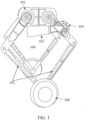
- the underactuated robot may be a wheel-legged robot shown in FIG. 1 .
- FIG. 1 is a schematic structural diagram of a robot with a left wheel-legged part and a right wheel-legged part of a single wheel-legged configuration according to an embodiment of this application.
- FIG. 1 exemplarily shows a schematic structural diagram of a robot 100.
- the wheel-legged robot 100 may include wheel-legged parts 103, and the wheel-legged part 103 includes a driving wheel 104 (also referred to as a foot part) and a plurality of joints.
- the wheel-legged robot 100 may also include a base part 101.
- the base part 101 refers to a main portion of the robot, for example, the base part may be a trunk part of the robot.
- the base part for example, may be a panel-like part or a cuboid-like part connected to the wheel-legged part of the robot.
- the robot may also include a base part connected to the wheel-legged part or an additional component arranged on the base part.
- a structural example of the robot is only illustrated above. The embodiment of this application is not limited by specific constituent components and connection ways of the robot.
- the driving wheel 104 in the wheel-legged part 103 may enable the wheel-legged robot 100 to walk and perform wheeled motion.
- the wheel-legged robot 100 may also include a controllable additional component (such as a tail).
- the tail may be configured to balance the wheel-legged robot, or assist the wheel-legged robot in moving.
- the tail may assist the wheel-legged robot in keeping balanced during the motion.
- the wheel-legged robot may also include a controllable robot arm which may be configured to execute operating tasks such as carrying, picking, and the like.
- the wheel-legged robot may include a multi-foot wheel-legged robot, such as a double-foot wheel-legged robot, a four-foot wheel-legged robot, and the like.
- the wheel-legged part 103 is a parallel-structure leg (a balance point is located between two legs of the two-foot wheel-legged robot 100).
- the wheel-legged part 102 of the robot 100 includes a left wheel-legged part and a right wheel-legged part.
- Each of the left wheel-legged part and right wheel-legged part includes a driving wheel and two parallel legs.
- the two parallel legs are connected to a central shaft of the driving wheel and configured to realize the motion control for the driving wheel.
- the left wheel-legged part includes a left driving wheel, a first left wheel-legged part and a second left wheel-legged part, and the first left wheel-legged part and the second left wheel-legged part are connected in parallel; and the right wheel-legged part 112, for example, includes a right driving wheel, a first right wheel-legged part, and a second right wheel-legged part, and the first right wheel-legged part and the second right wheel-legged part are connected in parallel.
- the left wheel-legged parts and the right wheel-legged parts are in mirror symmetry.
- the driving wheel for example, may be a driving wheel configuration of a single wheel, two wheels, four wheels or other number of wheels.
- the motion of each driving wheel may be controlled by two parallel legs or a plurality of concatenated legs.
- the embodiment of this application is not limited by a specific configuration type of the left and right wheel-legged parts and the number of the driving wheel.
- both the left wheel-legged part and the right wheel-legged part are of a single wheel-legged configuration.
- the single wheel-legged configuration refers to that the wheel-legged part includes only a single driving wheel.
- the left wheel-legged part and the right wheel-legged part may include the same number of joints and the same joint configuration, or the left wheel-legged part and the right wheel-legged part may have different numbers of joints or different joint configurations according to the practical need, or have different numbers of joints and different joint configurations.
- the embodiment of this application is not limited by a specific joint number and joint configuration of the left and right wheel-legged parts.
- the left and right wheel-legged parts each includes 5 joints with 2 rotational degrees of freedom.
- a height of a mass center of the wheel-legged part/base part and an inclination angle of the base part may be regulated by regulating the joints of the wheel-legged part 103.
- the leg of the robot may be of a concatenated structure or a parallel structure. Compared with the concatenated structural leg, the parallel structural leg can have higher stiffness, which may bear an impact that may be brought in a complicated motion.
- the driving wheel 104 may provide the wheel-legged robot 100 with the sliding ability.
- the double-foot wheel-legged robot 100 may also include an additional component 102.
- the additional component 102 is connected with the base part 101.
- the additional component 102 may be provided with a driven wheel 105.
- the additional component 102 includes 1 rotational degree of freedom.
- the motion of the additional component 102 may also affect the change of the base part 101 and the wheel-legged part 103.
- the location change of the additional component may drive the base part to have certain rotational velocity.
- the balance and posture of the robot 100 may be regulated by regulating the location of the additional component 102.
- the wheel-legged robot 100 not only has the flexibility of a wheeled robot but also the flexibility of a legged robot. Therefore, the wheel-legged robot 100 may move quickly on the flat ground, and may also cross the fluctuated road. However, for some wheel-legged robots (similar to the wheel-legged robot 100 shown in FIG. 1 ), there are only two contact points between the robot and the ground.
- the wheel-legged robot 100 is a non-minimum phase system, so that it is still difficult to perform balance control for the wheel-legged robot 100 in the practical application.
- due to the complicated mechanical structure of the (wheel-legged) robot it is difficult to determine dynamic characteristics of the (wheel-legged) robot. Since the traditional balance control method needs to know the dynamic characteristics of the robot, the traditional balance control method is difficult to perform the balance control for the robot without knowing the dynamic characteristics.
- an embodiment of this application provides a robot control method based on adaptive dynamic planning.
- the robot control method takes an output of a controller of a component (such as the driving wheel) of the robot calculated based on the adaptive dynamic planning as a reference parameter of the whole-body dynamic control, so that the controller of the joint can cooperate with the controllers of other joints, thereby improving the overall motion flexibility of the robot.
- the adaptive dynamic planning method may be implemented by at least one of a data-driven policy iteration (PI) scheme and a data-driven value iteration (VI) scheme.
- the robot control method provided by the embodiment of this application uses the adaptive dynamic planning (ADP) method and the whole-body dynamic method to design the controller enabling the robot with unknown dynamic characteristics to keep balanced during the motion.
- ADP adaptive dynamic planning
- the ADP fundamentally solves the problem of infinite-horizon LQR, but parameters of a system model are completely unknown. Therefore, the well-known Algebraic Riccati equation cannot be solved analytically.
- the embodiment of the invention realizes that a solution of the LQR problem can still be obtained by using the artificial intelligence scheme in a case that the LQR problem cannot be solved based on the system model.
- the embodiment of this application solves the optimal balance control problem of at least one joint controller of the robot by using policy iteration, value iteration or whole-body dynamic control technology without knowing the dynamic characteristics of the robot.
- the wheel-legged robot In the process of constructing the controller in the embodiment of this application, the wheel-legged robot only needs to travel for a period of time or trajectory under the control of a non-optimal controller or an arbitrary controller, and motion state data and control data corresponding to the period of time or trajectory are collected as training data.
- the quantity of the training data in the embodiment of this application is far less than a data volume required in the traditional reinforcement learning algorithm.
- the trained controller in the embodiments of this application gradually converges to the controller corresponding to an optimal solution of a linear quadratic regulation problem with the increase of a learning step length, so that the stability of a closed-loop system may be ensured, and the training process is greatly simplified.
- the training data does not need to be limited additionally, so that a design process of the controller of the wheel-legged robot is simplified.
- the data is acquired from the real robot, and the control policies obtained based on the data of the real robot are applied directly to the robot, so that it is unnecessary to consider the difference between analog control and real control, and the application effect of the controller on the real robot is improved.
- vec A a 1 T ⁇ a n T T .
- vecs(S) [ s 1,1 , 2 s 1,2 , ⁇ ,2 s 1, n , s 2,2 , 2 s 2,3 , ⁇ ,2 s n -1, n , s n , n ] T .
- vecv x x 1 2 , x 1 x 2 , ⁇ , x 1 x n , x 2 2 , ⁇ x n 2 T .
- FIG. 2 is an exemplary flowchart of a robot control method 200 according to an embodiment of this application.
- the method 200 may include step S201 to step S204.
- step S201 to step S204 may be performed on-line or off-line. This application is not limited thereto.
- the method 200 may be optionally applied to any robot including a wheel-legged part including a driving wheel and a plurality of joints.
- the robot 100 shown in FIG. 1 as an example, the method 200 is further described below.
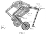
- the robot 100 in FIG. 1 is further marked with reference to FIG. 3 .
- the joints of the robot may be further identified to facilitate the construction of a dynamic model of the robot.
- the dynamic model is used for representing a change relationship between each joint and a centroid angle, an angular velocity, an angular acceleration, a joint torque, and an external contact force in a motion process of the robot.
- the dynamic model may describe the above-mentioned change relationship from the perspective of energy change.
- the complicated robot 100 shown in FIG. 1 may be marked in a generalized coordinate system of the robot.
- centers P 1 and P 2 of the driving wheels are shown as two separated points. A person skilled in the art may understand that P 1 and P 2 are actually the same point.
- q ⁇ , ⁇ and ⁇ ⁇ , ⁇ are respectively used for identifying parameters of each joint of the wheel-legged part, where q ⁇ , ⁇ identifies a rotational angle of the joint, and ⁇ ⁇ , ⁇ identifies a torque of the joint.
- q ⁇ 1,2 ⁇ identifies the rotational angle of the joint between a first linkage and the base part of the left wheel-legged part of the robot
- ⁇ ⁇ 1,2 ⁇ identifies the rotational torque of the joint between the first linkage and the base part of the left wheel-legged part of the robot.
- the angle and rotational torque of a tail joint may be set correspondingly.
- q ⁇ fb and q ⁇ fb respectively indicate an instantaneous angular velocity and an instantaneous angular acceleration of a robot body.
- the universal dynamic model shown in the following formula (1) may be constructed. Values of various parameters in the following formula (1) may be known or unknown, which is not limited by this application.
- M q q ⁇ + C q q ⁇ S T ⁇ + J f T f + J ⁇ T ⁇
- M q ⁇ R 6 + n j ⁇ 6 + n j , and M ( q ) is used for indicating a mass matrix of the robot.
- C q q ⁇ ⁇ R 6 + n j which is used for representing a gravity, a centrifugal force and a Coriolis force of the robot.
- the matrix S is used for selecting a driving joint from all joints, where in a case that a value of an element in S is 0, it is represented that the element is an un-driven joint. In a case that the element value is not 0, the element is identified as the driving j oint, f is a generalized force provided by the ground at a contact point where the robot contacts the ground. J f ⁇ R 3 n c ⁇ n j + 6 , J f is a concatenated contact Jacobian matrix for f. ⁇ is a closed-loop force that a front leg acts on a rear leg.
- n c is the number of contact points between the driving wheel and the ground.
- n ⁇ is the number of contact points between open-loop links.
- the wheel-legged part of the robot is a five-link mechanism. The number of the contact points between the open-loop links (such as between the points P 1 and P 2 in FIG. 3 ) of the closed-loop constraint of the five-linkage mechanism is 2.
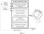
- FIG. 4 is a corresponding control architectural diagram of a robot according to an embodiment of this application; specifically, by taking the robot marked in FIG. 3 as an example, FIG. 4 shows a plurality of exemplary control tasks for the robot and an association between the control tasks. The combination and association of the exemplary control tasks are also referred to as dynamic whole-body dynamic control corresponding to the robot.
- step S201 Adaptively determine control information controlling rotation of the driving wheel based on motion information of the robot in the motion process.
- the motion process of the robot is relative to the stationary state of the robot.
- the wheel-legged part of the robot is in a moving state under the drive of the driving wheel and a plurality of joints.
- the driving wheel and a plurality of joints on the wheel-legged part are driven to move, and an acting force on the driving wheel and a plurality of joints may be provided by a connected actuating apparatus.
- the actuating apparatus is controlled by a controller through the control information.
- the motion information of the robot may include parameters such as a centroid angle, an angular velocity, an angular acceleration, a joint torque, an external contact force, and the like, and may also include a change relationship between each joint and each parameter.
- Adaptively determining the control information refers to a process of adaptively determining the control information that is most adaptive to the motion process of the robot by a data iteration method.
- the adaptively determining the control information controlling the rotation of the driving wheel includes: based on the motion information of the robot in the motion process, the controller for controlling the rotation of driving wheel is determined by a policy iteration method, or based on the motion information of the robot in the motion process, the controller for controlling the rotation of the driving wheel is determined by a value iteration method.
- a policy iteration method based on the motion information of the robot in the motion process
- the controller for controlling the rotation of the driving wheel is determined by a value iteration method.
- FIG. 4 also shows another example, which estimates a motion state of the robot by using a measurement value, and then inputs a value after the state estimation into a data processing module for adaptively determining the control information controlling the rotation of the driving wheel, so that the data module can quickly learn the measurement value corresponding to each moment so as to more efficiently calculate the optimal control information for controlling the rotation of the driving wheel.
- control information controlling the rotation of the driving wheel may be an acceleration of the driving wheel, or the torque of the driving wheel.
- the two physical quantities serving as the control information controlling the rotation of the driving wheel are not quite different in a mathematical sense. However, in a real physical system, not both of the two physical quantities may be measured accurately. Therefore, a person skilled in the art may select the physical quantity with good data test effect and more in line with the model for subsequent calculation and iteration according to a specific situation in an experiment.
- Step S202 Determine first control information for controlling a plurality of joints based on the control information controlling the rotation of the driving wheel, the first control information being used for keeping the robot balanced.
- the first control information may be control information for regulating and controlling the configuration of the robot.
- the gravity center of the robot may be lowered or raised to dynamically keep the balance of the robot.
- a rotational velocity of the driving wheel may not only affect a linear velocity of the robot, but also affect the traveling balance of the robot.
- the robot 100 shown in FIG. 1 and FIG. 3 in a case where the driving wheel 104 provides an excessively large acceleration, the robot 100 may fall backward quickly.
- the embodiment of this application takes the control information of the driving wheel as the reference information for controlling each j oint, so as to dynamically keep the balance of the robot by regulating the configuration of the robot, for example, lowering/raising the gravity center, in a case that the velocity of the driving wheel 104 is too high.
- the first control information may be an output of a wheel balance control task, and the wheel balance control task is described in detail below.
- Step S203 Determine second control information for controlling a plurality of joints based on a target trajectory of the robot, the second control information being used for making the robot move along the target trajectory.
- the second control information may be control information for regulating a posture of the base part, and the potential energy is converted into dynamic energy by regulating the posture of the base part so as to assist robot in moving.
- the robot 100 shown in FIG. 1 and FIG. 3 may convert the potential energy into the dynamic energy to assist the robot in moving by further regulating the posture of the base part.
- the robot travels in an S-shaped curve.
- the target trajectory is also used as a reference to assist the robot in regulating the posture and the velocity.
- the second control information may be an output of any one of a wheel motion and rotational control task, a base part posture control task and a tail part control task.
- the wheel motion and rotational control task, the base part posture control task and the tail part control task are described in detail below.
- Step S204 Determine a control torque respectively for controlling each joint in the plurality of joints based on a motion constraint condition of the robot, the first control information and the second control information.
- the motion constraint condition of the robot refers to a constraint condition that all parameters of the robot need to meet theoretically in the motion process.
- the motion constraint condition may be at least one of a dynamic constraint condition, a closed-loop linkage constraint condition, a nonholonomic constraint condition and a friction constraint condition.
- step S204 further, based on the first control information and the second control information, at least one candidate control torque combination corresponding to a plurality of joints of the robot is determined.
- the at least one candidate control torque combination satisfies the motion constraint condition of the robot; based on the at least one candidate control torque combination, a value corresponding to a dynamic whole-body dynamic target function of the robot is determined; and the candidate control torque combination enabling the dynamic whole-body dynamic target function to reach an extreme value is selected from the at least one candidate control torque combination, and each candidate control torque in the candidate control torque combination is used as the control torque respectively for controlling each joint in the plurality of joints.
- the dynamic whole-body dynamic control corresponding to the robot may be described as controlling each joint of the robot with a target of minimizing the total input energy of each joint and minimizing an error with the target trajectory in a case of ensuring the balance of the robot.
- the dynamic whole-body dynamic control target argminz ⁇ f ⁇ for the robot marked in FIG. 3 may be expressed with formula (2).
- q ⁇ des is a vector formed by combining sets of accelerations of the target trajectory set for each j oint
- q ⁇ is a vector formed by combining sets of accelerations of each joint in the motion process
- ⁇ des is a vector formed by combining sets of torques of the target trajectory set for each joint
- ⁇ is a vector formed by combining sets of torques of each joint in the actual motion process.
- f is a generalized force provided by the ground at a contact point where the robot actually contacts the ground.
- ⁇ is a closed-loop force that a front leg acts on a rear leg in the motion process of the robot.
- Subscripts W q , W ⁇ , W f , W ⁇ respectively identify weight coefficient matrices that need to be multiplied by q ⁇ , ⁇ , f and ⁇ in response to calculation of a norm of the formula (2).
- the control information that is determined by the adaptive dynamic planning may be used for controlling the driving wheel shown in FIG. 1 and FIG. 3 .
- the motion state and dynamical state of the driving wheel may correspondingly provide input reference or input limitation for various control tasks so as to change the posture and balanced state of the robot.
- active joints such as q ⁇ 1,2 ⁇ and q ⁇ 7,8 ⁇ ) in FIG.
- the 3 may rotate under a collective action of the driving wheel (such as q ⁇ 5,6 ⁇ ) and un-driven joints (such as q ⁇ 3,4 ⁇ and q ⁇ 9,10 ⁇ ) and the joint torque (such as ⁇ ⁇ 1,2 ⁇ and ⁇ ⁇ 5,6 ⁇ ) so as to regulate the posture of the robot, so that the robot keeps balanced.
- the driving wheel such as q ⁇ 5,6 ⁇
- un-driven joints such as q ⁇ 3,4 ⁇ and q ⁇ 9,10 ⁇
- the joint torque such as ⁇ ⁇ 1,2 ⁇ and ⁇ ⁇ 5,6 ⁇
- the rotation of the driving wheel under the control of the control information obtained by adaptive dynamic planning may provide the input reference Ref for at least one of the wheel balance control task and the wheel motion and rotational control task.
- the target trajectory may provide the input reference for the wheel motion and rotational control task, the base part posture control task and the tail part control task.
- the driving wheel and the target trajectory do not provide the input reference directly for other control tasks (such as torque control task and external force control task), by considering that each control task always needs to control the same robot component (such as the driving wheel, a connecting rod assembly, a joint hinge, and the like), a control effect of these control tasks is always limited by the driving wheel and the target trajectory.
- FIG. 4 shows four exemplary constraints, i.e., a dynamic constraint, a closed-loop linkage constraint, a nonholonomic constraint and a friction constraint.
- the dynamic model shown in formula (1) may be used as an example of the dynamic constraint so as to limit a change range of energy of the robot in the motion process.
- a person skilled in the art may understand that the limitations of the dynamic model are not limited to this.
- a simplified dynamic model may be constructed for the robot so as to simplify the corresponding dynamic model limitations of formula (1) in the dynamic whole-body dynamic control.
- formula (3) shows an example of the closed-loop linkage constraint for the robot in FIG. 3 .
- the closed-loop linkage constraint may also be shown in other manners. This application is not limited to this.
- J ⁇ q ⁇ + J ⁇ ⁇ q ⁇ 0
- J ⁇ T J P 1 , l T ⁇ J P 2 , l T J P 1 , r T ⁇ J P 2 , r T .
- J P 1 and J P 2 are Jacobian matrices corresponding to points P 1 and P 2 .
- Subscripts J ⁇ , l and J ⁇ , r respectively identify the left wheel-legged part and the right wheel-legged part.
- Formula (4) shows an example of a nonholonomic constraint for the robot in FIG. 3 .
- a person skilled in the art may understand that the nonholonomic constraint may also be shown in other manners. This application is not limited to this.
- J w 1,3 B q ⁇ B + J ⁇ w 1,3 q ⁇ 0
- J w 1,3 B is an x axis and a y axis of the Jacobian matrix of the driving wheel-ground contact point relative to the base part.
- the friction constraint may also be set based on the following hypotheses: a friction cone at a contact point between the ground and the robot in the practical motion process is approximated as a pyramid-shaped friction pyramid.
- a friction cone at a contact point between the ground and the robot in the practical motion process is approximated as a pyramid-shaped friction pyramid.
- the friction constraint may be expressed as
- a unilateral constraint may also be set correspondingly.
- An example of the unilateral constraint may be f i,z > 0.
- a control model of each control task may be determined correspondingly.
- the rotation of the driving wheel under the control of the control information obtained by adaptive dynamic planning may provide input reference for the wheel balance control task, while the target trajectory may provide the input reference for other control tasks.
- the rotational velocity of the driving wheel may affect the posture and velocity of the base part, while the posture and velocity of the base part may affect the balanced state of the robot.
- an expected acceleration q ⁇ fb of the base part may be calculated by using a PD control law (a proportional differential controller).
- a PD control law a proportional differential controller
- at least some parameters of the PD control law are obtained based on the input reference for the posture and the input reference for the velocity.
- the input reference for the posture is also referred to as a reference posture, which indicates that: the rotation of the driving wheel under the control of the control information obtained by adaptive dynamic planning leads to the change of the posture of all joints except for the joint q ⁇ 5,6 ⁇ .
- the input reference for the velocity is also referred to as a reference velocity, which indicates that: the rotation of the driving wheel under the control of the control information obtained by adaptive dynamic planning leads to the change of velocity of all joints except for the joint q ⁇ 5,6 ⁇ . That is, q ⁇ i des in formula (2) may also be expressed approximately by using formula (5).
- ⁇ i des in formula (2) may also be further expressed approximately by using formula (6).
- formula (6) it is assumed that the torque of other joints ⁇ i des ( i ⁇ 3,4) except for the joint q ⁇ 5,6 ⁇ is approximated as zero.
- the input reference for the posture includes: a distance from the gravity center of the robot to a center of a connecting line of the driving wheels projected on the ground (for example, identified withstate_com_p).
- the input reference for the velocity includes: a differential velocity obtained based on the distance from the gravity center of the robot to the center of the connecting line of the driving wheels projected on the ground (for example, identified with state_com_v), and a linear velocity of the wheels (identified with wheel x_v), wherein the differential velocity refers to the velocity obtained by performing differential calculation on the distance.
- the above PD control law may take state_com_p, state_com_v and wheel_x_v as input states to calculate the reference acceleration or the reference torque of the driving wheel.
- the input reference for the posture may also include: an equivalent inclination angle of the base part.
- the equivalent inclination angle theta equi may be calculated by using state_com_p and a mass center height.
- theta_equi atan(state_com_p/height).
- the input reference for the velocity includes: an equivalent inclination angle acceleration theta_dot_equi.
- the equivalent inclination angle may be calculated by using state_com_v and the mass center height.
- theta_dot_equi state_com_v/height.
- the above PD control law may use the equivalent inclination angle and the equivalent inclination angle acceleration to calculate the reference acceleration or the reference torque of the driving wheel.
- this application provides a robot.
- the robot includes: a wheel-legged part; a base part connected to the wheel-legged part, wherein the wheel-legged part and the base part include a plurality of joints; and a controller, the controller being arranged on the robot and being capable of performing the above robot control method.
- the embodiment of this application provides a whole-body dynamic control method based on adaptive dynamic planning.
- the whole-body dynamic control method takes an output of a controller of a joint of the robot calculated based on the adaptive dynamic planning as a reference parameter of the whole-body dynamic control, so that the controller of the joint can cooperate with controllers of other joints, thereby improving the overall flexibility of the motion of the robot.
- the embodiment of this application optionally combines the whole-body dynamic technology, and takes the output of the controller of the joint of the robot calculated based on the adaptive dynamic planning as the reference parameter of the whole-body dynamic control, so that the controller of the joint can cooperate with the controllers of other joints, thereby improving the overall flexibility of the motion of the robot.
- the embodiment of this application provides a policy iteration method based on adaptive dynamic planning.
- Fig. 5A and FIG. 5B show an exemplary flowchart of a process of updating a controller for performing a robot control method according to an embodiment of this application.
- the robot control method is described more specifically below in combination with FIG. 5A to FIG. 5B .
- the robot may be a robot 100 shown in FIG. 1 to FIG. 4 .
- the schemes shown in FIG. 5A to FIG. 5B may be performed on-line or off-line. This application is not limited to this.
- the controller performing the robot control method may be a first controller.
- Step S501 Control the robot to move by using the first controller, and acquire motion state data and control data in the motion process.
- accurate dynamic characteristics of the robot are unknown, or only some dynamic characteristics of the robot can be determined roughly.
- the dynamic characteristics of the robot may also involve some variable parameters.
- the height of the gravity center of the robot 100 may be changed.
- the mass of the robot 100 may also be changed correspondingly.
- the linear balance parameter matrix of the first controller is a stable initial gain matrix.
- a control force provided by the controller at a moment is negatively related to a product between the linear balance parameter matrix and the motion state data of the robot at the moment.
- the robot 100 at least includes: a wheel-legged part including a plurality of joints, a base part connected to the wheel-legged part, and a driving motor for controlling the driving wheel in the wheel-legged part.
- the motion data includes: a pitch angle of the base part, a velocity of the pitch angle of the base part, and a linear velocity of the driving wheel.
- the control data includes: an output torque of the driving motor.
- both the motion data and the control data may be acquired discretely by relevant measuring instruments, both the motion data and the control data correspond to a plurality of discrete consecutive moments or correspond to a plurality of consecutive time intervals.
- the first controller is a non-optimal controller.
- the non-optimal controller for example, is a controller that can only enable the robot 100 to stumble along the target trajectory.
- the first controller as the non-optimal controller may be the controller corresponding to the simplified dynamic characteristic.
- the dynamic model may be simplified as an equivalent dynamic model only composed of the driving wheel and the base part.
- the first controller may be used for controlling the robot to move in a quasi-balanced state.
- the robot may swing around a balance point at a certain amplitude.
- the output of the first controller may be used as the control data.
- the control data may be obtained by acquiring the output of the controller (for example, detecting a driving force of the driving wheel) on a real robot. This application does not limit a method for acquiring the control data.
- one or more first controllers obtained by using a value iteration scheme described in detail below may also be used for controlling the robot to move.
- the value iteration scheme may be used for determining (such as off-line) the first controller.
- the variable parameter is a height of the robot.
- the first value is 0.38 m
- a second value is 0.5 m.
- the value iteration scheme may be used for determining the optimal controller controlling the robot to travel in a straight line, and the controller is used as the first controller.
- the height of the robot 100 is regulated to 0.5 m by changing the angle of the joint.
- the first controller is continuously used for controlling the robot with the increased height to travel for a period of time or a distance, and the motion data and control data are acquired correspondingly.
- the motion data and the control data are subsequently used as training data of a second controller so as to obtain the optimal controller in a case where the variable parameter is the second value.
- both the first value and the second value are merely examples. This application is not limited to this.
- the value iteration scheme can determine the first controller adaptive to the robot with the height of 0.38 m, in a case where the body of the robot is changed, it is necessary to off-line re-calculate the second controller adapted to the robot after the height change. The off-line calculation may be time-consuming, and may cause the interruption of the motion of the robot.
- step S502 to step S503 may be used for constructing the second controller by using a policy iteration scheme.
- step S502 Update a linear balance parameter matrix of the first controller by a policy iteration method according to the motion state data and the control data.
- step S503 Construct the second controller corresponding to the dynamic characteristics of the robot based on the updated linear balance parameter matrix.
- the robot controlled by the second controller may have better control effect in the motion process.
- the left-right swinging amplitude of the robot controlled by the second controller corresponding to the dynamic characteristics of the robot at the balance point may be smaller compared with the robot controlled by the first controller.
- the robot controlled by the controller may converge quickly nearby the balance point in the motion process, or the vibration of the robot is smaller, or the control velocity is higher, or overshoot is smaller, or a steady-state error is smaller, and the like.
- any controller has the same control effect as the controller, but the control input of the controller is smaller. This application is not limited to this.
- the traveling robot 100 is taken as an example for description.
- the robot 100 in a balanced state may be in a stable balanced state in the linear motion dimension and the rotational motion dimension.
- the robot 100 in the balanced state can be kept in the same/similar state as being defined by the balance point in the motion process, or can be restored to the state defined by the balance point with maximum velocity/minimum energy consumption in the motion process.
- the state defined by the balance point may be the state of the robot 100 in which the pitch angle is zero, an angular velocity corresponding to the pitch angle is zero, and the linear velocity is the target velocity.
- the posture of the robot 100 at the moment is in a straight-up state, and the robot 100 at the moment does not have the velocity in the rotational motion dimension but only has the target velocity in the linear motion dimension.
- the robot 100 in the quasi-balanced state is in a state defined nearby the balance point in the motion process.
- the robot may be in an intermediate state from the steady balanced state to the unstable balanced state in the linear motion dimension and the rotational motion dimension.
- the robot 100 in the quasi-balanced state may need the driving wheel to provide the large force and torque in the motion process to ensure the robot not to fall.
- the robot 100 at the moment may tilt left and right, and the robot 100 at the moment not only has the velocity in the linear motion dimension, but also has the velocity in the rotational motion dimension.
- the robot 100 in the quasi-balanced state may also be in a state close to the unstable balanced state in the linear motion dimension or the rotational motion dimension at a certain moment during the motion, as long as the robot can be restored to the normal marching state by using the driving force of the driving wheel 104.
- the robot 100 in the balanced state can be always kept at the straight-up posture to travel in the straight line at a constant velocity, that is, a central axis of the base part of the robot 100 in the unstable balanced state can be always perpendicular to a horizontal line and does not have the velocity/acceleration in the rotational motion dimension.
- the base part of the robot 100 in the quasi-balanced state may have an inclination angle (pitch angle), and have the velocity/acceleration in the rotational motion dimension.
- the robot may be first controlled by the first controller to travel for a period of time or trajectory, and the motion state data and control data corresponding to the period of time or trajectory is acquired as the training data.
- the embodiment of this application can also determine the second controller as the optimal controller correspondingly by using the policy iteration.
- the embodiment of this application uses the value-driven policy iteration scheme to calculate the linear balance parameter matrix so as to construct the controller.
- the control effect of the controller is better than the non-optimal controller, or better than the control effect of the first controller in some cases.
- the constructed controller can converge to the controller corresponding to an optimal solution of a linear quadratic regulation problem.
- the controller corresponding to the optimal solution of the linear quadratic regulation problem is the controller corresponding to the accurate dynamic characteristics of the robot.
- the controller corresponding to the optimal solution of the linear quadratic regulation problem can minimize a cost functional of the robot in the motion process, so that the robot travels along the target trajectory with the optimal control effect in the balanced state.
- the policy iteration scheme and a calculation scheme of the linear balance parameter matrix may be further described below, which is not described here.
- the quantity of the training data in the embodiment of this application is far less than the data volume required in the traditional reinforcement learning algorithm.
- the trained controller in the embodiment of this application gradually converges to the controller corresponding to the optimal solution of the linear quadratic regulation problem with the increase of a learning step length, so that the stability of the closed-loop system may be ensured, and the training process is greatly simplified.
- the training data does not need to be limited additionally, so that a design process of the controller of the wheel-legged robot is simplified.
- the embodiment of this application may perform data acquisition directly on the real robot, and the trained controller is directly applied to the real robot. The embodiment of this application does not need to perform data acquisition in an emulator based on a physical engine, so that problems brought by migrating the data from a virtual world to a real world are omitted.
- the embodiment of this application correspondingly provides a method for controlling the robot.
- the method includes: a motion instruction is received, the motion instruction indicating a motion trajectory of the robot; a driving force of a driving wheel is controlled according to the motion instruction, so that the robot moves under the control of the first controller, and motion state data and control data are acquired in the motion process; and a second controller corresponding to dynamic characteristics of the robot is constructed by a policy iteration method based on the motion state data and the control data, and the driving force of the driving wheel is controlled by the second controller to make the robot move stably.
- the robot under the control of the controller has better control effect in the motion process, for example, closer to the balance point.
- the method for controlling the robot according to the embodiment of this application can enable the robot with unknown dynamic characteristics to learn the data in the motion process, and gradually improves/generates the controller corresponding to the dynamic characteristics of the robot, so that the stable motion can be finally realized.
- the robot may be controlled by the control input of the first controller to move for a period of time so as to obtain the training data, in this case, the embodiment of this application realizes the improvement on the non-optimal controller in a case of unknown dynamic characteristics or change of the dynamic characteristics, and generates the second controller corresponding to the (accurate) dynamic characteristics of the robot. That is, the embodiment of this application may enable the robot to be controlled flexibly without the accurate dynamic model.
- the motion process of the robot 100 may be regarded as a consecutive time linear system on mathematics. It is assumed that the robot 100 has the controller corresponding to the optimal solution of the linear quadratic regulation problem, which can minimize the cost functional corresponding to the motion process of the robot. For example, the controller corresponding to the optimal solution of the linear quadratic regulation problem can minimize the cost that the robot is located nearby the balance point and can enable the robot to travel along the target trajectory with minimal energy consumption.
- a ⁇ R n ⁇ n and B ⁇ R n ⁇ 1 .
- J is the cost functional of the consecutive time linear system
- Q is a real symmetric and positive semidefinite matrix
- Q is a real symmetric and positive semidefinite matrix
- Q is observable
- x is related to the robot configuration and the wheel balance task. For example, referring to the example in FIG. 4 , in a case where the controller of the driving wheel needs to be determined, x optionally includes the pitch angle, the angular velocity of the pitch angle and the linear velocity of the robot, and u is a sum of input torques of the two wheels.
- an Algebraic Riccati equation (formula (8)) on mathematics may be used as the solution of the following linear quadratic regulation (LQR) defined by formula (7).
- LQR linear quadratic regulation
- a T P ⁇ + P ⁇ A ⁇ 1 r P ⁇ BB T P ⁇ + Q 0
- u *( t ) is the controller corresponding to the optimal solution of the linear quadratic regulation problem
- u *( t ) - K * x ( t )
- K ⁇ 1 R B T P ⁇
- a - BK 0 is Hurwitz.
- K k + 1 1 R B T P k
- a scheme for updating the linear balance parameter matrix of the first controller by using the policy iteration method in step S502 may be determined exemplarily.
- step S502 may further include: the motion state data and control data corresponding to a plurality of time intervals are nonlinearly combined to determine a training data set, and an iteration relationship function is determined based on the training data set; and multiple policy iterations are performed on an iteration target according to the iteration relationship function to approximately obtain the linear balance parameter matrix corresponding to the dynamic characteristics of the robot.
- Step S502 is described below with the example described in FIG. 1 to FIG. 4 .
- the first controller u 0 may be used for controlling the robot to move, and the motion state data and control data corresponding to a plurality of time intervals are acquired correspondingly.
- a time derivative of x ( t ) T P k x( t ) may be exemplarily shown by formula (12).
- d dt x t T P k x t x t T A T P k + P k A x t + 2 u 0 B
- P k x t x t T A k T P k + P k A k x t + 2 K k x t + u 0 B
- the motion state data is acquired by a sensor at a certain time interval in a period of time, and respectively corresponds to the motion state of the robot at each discrete moment in a period of time. Therefore, the motion state data and the control data of the first controller may correspond to a plurality of time intervals in [ t 0 , t r ]. Any time interval t to t + ⁇ t in the plurality of time intervals may be written as [ t, t + ⁇ t ], and a duration ⁇ t may be determined according to a data acquisition time interval that can be reached by the robot sensor.
- the motion state data and control data corresponding to a plurality of time intervals may be combined nonlinearly so as to be used for constructing the iteration relationship function.
- the motion state data and the control data after integral operation are used as training data for participating in a policy iteration process for the iteration target item in step S502 so as to approximately obtain the linear balance parameter matrix corresponding to the dynamic characteristics of the robot. It is to be noted that the following description is only an exemplary integral operation. This application is not limited to this.
- the exemplary formula (13) may be determined by taking integrals of both sides of formula (12) in the time interval [ t, t + ⁇ t ], and re-arranging the formula (12).
- K k + 1 x d ⁇ ⁇ ⁇ t t + ⁇ t x t T Q k x t d ⁇ .
- the time integral of the motion state data between any two adjacent moments t and t + ⁇ t may be related to at least one of the following items: a quadratic term of the motion state data of moment t , a quadratic term of the motion state data of moment t + ⁇ t , a product between the motion state data of the moment t and the motion state data of the moment t + ⁇ t , a product between the control data of the moment t and the motion state data of the moment t , a product between the control data of the moment t + ⁇ t and the motion state data of the moment t + ⁇ t , and the like.
- the control data of the moment t is the control data controlling the robot to travel by using the first controller.
- the embodiment of this application optionally defines the following three matrices as exemplary elements in the training data set by using formula (14), i.e. first matrix ⁇ xx , second matrix ⁇ xx , and third matrix ⁇ xu .
- Each matrix corresponds to the nonlinear combination of the motion state data and control data in multiple time intervals, for example, involving the integral operation, product calculation, and the like.
- any element x ⁇ x t i t i + ⁇ t in the first matrix ⁇ xx corresponds to a product of any two items or a difference of quadratic terms of any one of the pitch angle of the base part, the angular velocity of the pitch angle of the base part and the linear velocity of the driving wheel at the moment t i and the moment t i + ⁇ t .
- Any element ⁇ t i t i + ⁇ t x ⁇ x d ⁇ in the second matrix ⁇ xx corresponds to a product of any two items or a product of quadratic terms of any one of the pitch angle of the base part, the angular velocity of the pitch angle of the base part and the linear velocity of the driving wheel at the moment t i and the moment t i + ⁇ t .
- Any element ⁇ t i t i + ⁇ t x u 0 d ⁇ in the third matrix ⁇ xu corresponds to an integral of a product between any one of the pitch angle of the base part, the angular velocity of the pitch angle of the base part and the linear velocity of the driving wheel at the moment t i and the moment t i + ⁇ t and the driving force controlled by the first controller.
- the configurations of different robots may correspond to different matrices. The above is only used as an example. This application is not limited to this.
- an equation set of formula (13) may be exemplarily written in a form of formula (15).
- the iteration relationship function (such as formula (15)) obtained based on formula (13) is shown exemplarily below, where the iteration target item includes the to-be-iterated linear balance parameter matrix, and a solution of the Lyapunov equation with the to-be-iterated linear balance parameter matrix as a parameter. This application is not limited to this.
- ⁇ k vec P k vec K k + 1 ⁇ k
- vec( ⁇ ) identifies vectorization of contents in brackets.
- ⁇ k E R r ⁇ ( n 2 + n ) , and ⁇ k ⁇ R r may be defined as the form shown in formula (16).
- k indicates the number of policy iterations
- P k is the solution of the Lyapunov equation in the k th policy iteration
- K k is the linear balance parameter matrix used in the k th policy iteration
- K k +1 is the linear balance parameter matrix in the (k+1) th policy iteration.
- FIG. 6 is another structural view of the robot 100.
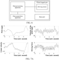
- FIG. 7A shows the motion state data and the control data in the motion process of the robot controlled by the first controller.
- FIG. 7B shows a convergence process of the linear balance parameter matrix in a process of constructing the controller corresponding to the dynamic characteristics of the robot, where a height of the base part of the robot is 0.5 m and 0.6 m respectively.
- FIG. 7C shows the motion state data that the robot is controlled respectively by the first controller and the second controller to travel in the straight line in a case where the height of the base part is 0.6 m.
- the robot 100 also includes a data acquisition apparatus, a data processing apparatus and a driving motor.
- the data acquisition apparatus may be configured to: acquire the motion state data and the control data of the robot in the motion process in a case where the robot is controlled by the first controller to move.
- the data acquisition apparatus may include: a first sensor, configured to measure a pitch angle ⁇ of the base part and an angular velocity ⁇ of the pitch angle of the base part; and a second sensor, configured to measure a rotational angular velocity ⁇ l and ⁇ r of a left driving wheel and a right driving wheel.
- the first sensor may be an inertial measurement unit (IMU), which may include a three-axis gyroscope, a three-axis accelerometer, or a three-axis magnetometer.
- the second sensor may be a motor encoder with a sampling frequency of 200 Hz.
- the data processing apparatus is configured to: update the linear balance parameter matrix of the first controller by a policy iteration method according to the motion state data and the control data; and construct the second controller corresponding to the dynamic characteristics of the robot based on the updated linear balance parameter matrix.
- this application only gives an example of controlling the driving wheel 104 by the first controller or the second controller.
- the scheme of this application may also be used for controlling other components of the robot.
- the driving wheel is only used for controlling the forward and backward motion of the robot, for a curved target trajectory, a controller for controlling a yawing angle is also needed for controlling the steering of the robot.
- the data processing apparatus calculates the control data of the first controller based on the given target trajectory.
- the first controller is the optimal controller that can control the robot 100 to travel upright and is obtained by a value iteration method in response to the minimal height of the robot. Specifically, the minimal height of the robot is 0.33 m. Further, a control frequency of the data processing apparatus is optionally 1000 Hz.
- the motion data and the control data may be used for calculating the first matrix ⁇ xx , the second matrix ⁇ xx , and the third matrix ⁇ xu .
- the data needs a consecutive signal of x and u. Therefore, in a case where the first controller and the controller corresponding to the dynamic characteristics of the robot control the robot 100 to move, the data processing apparatus may be further configured to calculate the integral by using the trapezoidal integral.
- a step length of the trapezoidal integral is 0.01 s, which is the same as a sampling period.
- the height of the robot may be increased to 0.5 m
- the exploration noise is usually used in the fields of learning and system recognition.
- the exploration noise may trigger various system behaviors to avoid the repeated data acquisition.
- the exploration noise ⁇ (t) sin(10 ⁇ t) + 0.4cos(6 ⁇ t).
- the same sinusoidal noise is added to the first controller u 0 (t) and the second controller u(t) to simulate the external disturbance acting on the wheel.
- two controllers are robust to the noise, and have the same control performance.
- the control effect of the updated gain K 1 is better in the regulation of the pitch angular velocity ⁇ ⁇ ⁇ , , so that the travel state of the robot is more stable.
- the embodiment of this application provides a value iteration method based on adaptive dynamic planning.
- the value iteration method based on the adaptive dynamic planning can calculate the controller converging to the dynamic characteristics of the robot without knowing the dynamic characteristics of the robot.
- the controller corresponding to the accurate dynamic characteristics of the robot is the controller corresponding to the optimal solution of the linear quadratic regulation problem, which can make the robot travel along the target trajectory with the optimal control effect in the balanced state.
- FIG. 8 is a flowchart of a value iteration scheme according to an embodiment of this application.
- the motion process of the robot 100 may be regarded as a consecutive time linear system on mathematics. It is assumed that the robot 100 has the controller corresponding to the optimal solution of the linear quadratic regulation problem, which can minimize the cost functional corresponding to the motion process of the robot. For example, the controller corresponding to the optimal solution of the linear quadratic regulation problem can minimize the cost that the robot is located nearby a balance point and can enable the robot to travel along the target trajectory with minimal energy consumption.
- formula (7) and formula (8) are already illustrated.
- the matrices A and B in formula (7) and formula (8) are known.
- u*(t) can be correspondingly solved.
- P (s) may converge to P*.
- the embodiment of this application shows a construction process of the first controller for performing the robot control method, which specifically includes step S801 to step S803.
- Step S801 Control the robot to move, and acquire the motion state data and control data in a motion process, diversity measures of the motion state data and control data being greater than a predetermined threshold.
- the robot may be controlled to move along a predetermined trajectory, and the motion state data and control data in the motion process may be acquired.
- the predetermined trajectory may be roughly estimated based on structural characteristics, motion characteristics and power characteristics of the robot so as to acquire the motion data of the robot in various motion situations (scenarios), so that the diversity measures of the motion state data and control data are high enough (for example, at least greater than the predetermined threshold).
- the diversify measure may be represented by information entropy, which represents that the motion state data and control data both have sufficient values that are not repeated/not the same.
- the diversity measure may also be represented by a data characteristic quantity.
- the robot may be controlled by any controller to move along the predetermined trajectory.
- the robot may be controlled manually to move in the straight line at different accelerations no matter whether the robot is in a state of balanced and stable motion.
- the robot shown in FIG. 1 to FIG. 4 in a case where the driving wheel 104 provides an excessively large acceleration, the robot 100 may fall backward quickly. In a case where the driving wheel 104 provides excessively small acceleration, the robot cannot arrive at the destination quickly and may tilt forward.
- the motion state data and control data satisfying the diversity measures may be acquired by the following methods.
- a driving motor may be first controlled to output a first torque, so that the robot loses the balance due to low-velocity motion.
- the first torque may be a small value, so that in a case where the driving motor is controlled to output the first torque, the mass center of the base part of the robot is first raised and then lowered, and the front end of the base part contacts the ground in response to that the robot loses the balance.
- the driving motor may also be controlled to output a second torque, so that the robot loses the balance due to high-velocity motion.
- the second torque may be a large value, so that in a case where the driving motor is controlled to output the second torque, the mass center of the base part of the robot is first raised and then lowered, and the rear end of the base part contacts the ground in response to that the robot loses the balance.
- the driving motor may also be controlled to output a third torque, so that the robot keeps balanced for a period of time.
- the driving motor is controlled to output the third torque
- the mass center of the base part of the robot is kept at a same height in a case where the robot keeps balanced.
- the driving motor is controlled to output a fourth torque, so that the robot keeps a quasi-balanced state for a period of time, and the robot in the quasi-balanced state is located nearby a balance point in the motion process.
- the driving motor is controlled to output the fourth torque
- the base part of the robot swings back and forth in a case where the robot keeps the quasi-balanced state.
- Step S802 Calculate the linear balance parameter matrix by a value iteration method according to the motion state data and the control data.
- Step S803 Construct the first controller corresponding to the dynamic characteristics of the robot based on the linear balance parameter matrix. Compared with the robot controlled by a remote controller, the robot controlled by the controller corresponding to the dynamic characteristics of the robot has better control effect in the motion process.
- the controller corresponding to the dynamic characteristics of the robot is a linear controller.
- the controller corresponding to the dynamic characteristics of the robot provides the product between the linear balance parameter matrix that is negatively related to the required control torque and the motion state data of the robot.
- step S802 in FIG. 8 may further include: an integral operation is performed respectively on the motion state data and the control data corresponding to a plurality of time intervals, and an iteration relationship function is constructed; and value iteration is performed on an iteration target item according to the iteration relationship function to approximately obtain the linear balance parameter matrix corresponding to the dynamic characteristics of the robot.
- the linear balance parameter matrix K is 1 R B T P s , where s is approximate to negative infinity.
- Step S802 is described below respectively with the examples described in FIG. 1 to FIG. 4 .
- the motion state data for training and the control data for training may be obtained.
- the motion state data for training and the control data for training are the motion data and the control data at a moment before the falling of the robot (for example, the front end/rear end of the base part or the tail are not in contact with the ground). That is, at least in the motion process, based on formula (18), the following formula (19) is established.
- the motion state data is acquired by the sensor at a certain time interval in a period of time, and respectively corresponds to the motion state of the robot at each discrete moment in a period of time. Therefore, the motion state data and the control data of the first controller may correspond to a plurality of time intervals in [t 0 , tr]. Any time interval t i to t i+1 in the plurality of time intervals may be written as [t, t + ⁇ t], and a duration ⁇ t may be determined according to a data collection time interval that can be reached by the robot sensor.
- the integral operation may be performed respectively on the motion state data and the control data corresponding to a plurality of time intervals to construct the iteration relationship function.
- the motion state data and the control data after the integral operation are used as training data for participating in a value iteration process for an iteration target item so as to approximately obtain the linear balance parameter matrix corresponding to the dynamic characteristics of the robot. It is to be noted that the following description is only an exemplary integral operation. This application is not limited to this.
- the linear balance parameter matrix K * can be generated by value iteration, and the whole process does not depend on the model information (A, B). That is, in a case where the iteration target item converges in the value iteration process, the value iteration may be stopped. According to the converged iteration target item, the linear balance parameter matrix corresponding to the dynamic characteristics of the robot is re-constructed.
- the first to the third matrices are constructed as the training data.
- the quantity of the training data in the embodiment of this application is far less than the data volume required in the traditional reinforcement learning algorithm.
- the iteration relationship function (such as formula (20)) is constructed correspondingly, so that the target iteration item (such as P (s), K (s) and H (s)) converges gradually with the increase of a learning step length.
- the converged target iteration item may obtain a controller.
- the controller converges to the controller corresponding to the optimal solution of the linear quadratic regulation problem, thereby ensuring the stability of the closed-loop system, and greatly simplifying the training process. No additional limitation is needed for the training data in the whole process, so that the design process of the controller of the robot is simplified.
- the robot 100 also includes the data acquisition apparatus, the data processing apparatus and the driving motor shown in FIG. 6 .
- the data acquisition apparatus may be configured to: acquire the motion state data of the robot.
- the data processing apparatus is configured to: acquire the control data corresponding to the motion state data; calculate the linear balance parameter matrix by the data iteration method according to the motion state data and the control data, where diversity measures of the motion state data and the control data are greater than a predetermined threshold; and construct the controller corresponding to the dynamic characteristics of the robot based on the linear balance parameter matrix.
- the data processing apparatus may be further configured to further process the data acquired by the data acquisition apparatus.
- this application only gives an example of controlling the driving wheel 104.
- a person skilled in the art may understand that the scheme of this application may also be used for controlling other components of the robot.
- the data processing apparatus sets the control data for training based on the given target trajectory. Just as shown in FIG. 3 , this application does not limit a specific control law of the controller for training. In order to illustrate the non-limitation of this application for the controller for training, the following description may take an example that the experimenter manually controls the robot to move to extract the motion data and the control data. Further, the control frequency of the data processing apparatus is 1000 Hz.
- the motion data and the control data may be used for calculating ⁇ xx, ⁇ xx and ⁇ xu . These data need a consecutive signal of x and u.
- the experimenter cannot accurately know the dynamic characteristics of the robot 100, and the controller of the robot cannot be accurately regulated timely in a case where the robot is manually controlled, resulting in falling of the robot.
- the acquired motion state data may also be further processed so as to obtain the controller corresponding to the dynamic characteristics of the robot as soon as possible.
- at least one motion data collector or motion data acquisition thread may be used for acquiring the motion state data in the motion process.
- the repeated motion state data is removed.
- frequencies (imu frequency, control frequency, and data storage frequency) of different motion data collectors/threads may store the same data. Therefore, while the data is processed off-line by using the value iteration scheme or the policy iteration scheme, whether there is the same data is determined based on the time, and the repeated data is removed.
- the error of a main computer on the robot in multi-thread data acquisition may be corrected further.
- the control thread since the control thread is not completed accurately within 0.001 s every time, there is repeated time in data. For example, due to the delay of the control thread, it takes 3*0.001 s to complete a data acquisition, so the thread for storing the data may save three sets of the same data (repeated data) at the same time. Therefore, the repeated data is removed during data processing. Based on this, in a case where differential calculation for velocity is needed, the real time difference (system time difference of industrial computer) rather than the ideal control period (0.001 s) is needed. Further, for the specific motion state data/control data, for example, the angular velocity, linear velocity and torque of the robot, the filter processing is further needed so as to reduce the error in the data acquisition process.
- the data in a case where the data may be acquired for multiple times, only the motion state data in a case where the pitch angle of the base part of the robot is within a predetermined range may be acquired in the motion process of the robot.
- the data of a linear portion (the inclination angle is within +/- 15 degrees) may be spliced after multiple data acquisitions.
- the motion state data and the control data in response to the inclination angle within +/- 15 degrees may be spliced after completing the integrals ⁇ xx, ⁇ xx, and ⁇ xu .
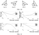
- the following shows an exemplary experiment of calculating the controller corresponding to the dynamic characteristics of the robot by using a data iteration scheme. As shown in FIG.
- the minimal height of the robot is 0.33 m.
- the motion instruction is directly given manually by the remote controller to indicate the torque of the driving wheel.
- the robot is started from an initial state (shown in a state A), and moves with the driving wheel (shown in a state B and a state C) and finally falls (state D). Since the robot finally loses the balance, the remote controller in this case is not the quasi-balanced controller.
- the same process is repeated for three times.
- the data acquired in three times is drawn in FIG. 11 , where the torque is a total torque of the two driving wheel motors.
- the torque is a total torque of the two driving wheel motors.
- the data approximate to a linear zone of a simplified model is used, that is, the inclination angle is greater than -20 degrees and less than 20 degrees.
- the duration of the three data acquisition processes is 0.515 seconds, 0.155 seconds and 0.586 seconds respectively, which is 1.256 seconds in total. Any non-professional can easily collect these short-term data by manually inputting the torque through the remote controller.
- the data iteration scheme may be performed off-line, various parameters may be easily regulated to enable the iteration item to converge.
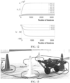
- the controller corresponding to the dynamic characteristics of the robot is constructed.
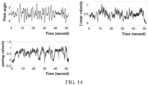
- the controller is used for controlling the real robot to travel in a path shown in FIG. 13 , the test data of the inclination angle (generally within +/-2 degrees), linear velocity and yawing velocity shown in FIG. 14 is obtained, so that the controller with sufficiently high robustness and stability can be obtained by adopting the data iteration scheme.
- controller with the control information may also be used for controlling other motions. This application is not limited to this.
- the robustness of the controller with the control information is far higher than the PID controller, that is, in a case where the robot 100 suffers external disturbance, the robot controlled by the controller with the control information can be restored to balance quickly.
- the optimal balance control problem of the robot without knowing the dynamic characteristics of the robot is solved.
- the wheel-legged robot under the control of the non-optimal controller/any controller only needs to travel for a period of time or trajectory, and the motion state data and the control data corresponding to the time of period or the trajectory are collected as training data.
- the quantity of the training data in the embodiment of this application is far less than the data volume required in the traditional reinforcement learning algorithm.
- the trained controller in the embodiments of this application gradually converges to the controller corresponding to the optimal solution of the linear quadratic regulation problem with the increase of the learning step length, so that the stability of the closed-loop system may be ensured, and the training process is greatly simplified.
- the training data does not need to be limited additionally, so that a design process of the controller of the wheel-legged robot is simplified.
- the robot includes a wheel-legged part, and the wheel-legged part includes a driving wheel and a plurality of joints.
- the apparatus includes:
- the adaptive processing module is further configured to determine the control information for controlling the rotation of the driving wheel in a policy iteration method based on the motion information of the robot in motion process.
- the adaptive processing module is further configured to determine the control information for the controlling rotation of the driving wheel in a value iteration method based on the motion information of the robot in the motion process.
- control torque determination module is configured to:
- parameters of the dynamic whole-body dynamic target function include at least one of the following items:
- the motion constraint condition of the robot includes at least one of the following items: a dynamic constraint condition, a closed-loop linkage constraint condition, a nonholonomic constraint condition, and a friction constraint condition.
- At least some of the dynamic constraint conditions are determined based on the dynamic model of the robot; and the dynamic model is used for representing a change relationship between each joint and a centroid angle, an angular velocity, an angular acceleration, a joint torque, and an external contact force in the motion process of the robot.
- one end of the wheel-legged part facing the driving wheel is connected to the base part, and the first control information determination module is further configured to: determine influencing data of a rotational velocity of the driving wheel on the posture and velocity of the base part based on the control information and the motion information of the robot; and determine an expected acceleration of the base part based on the influencing data, and determine the first control information for controlling the plurality of joints based on the expected acceleration.
- the robot further includes a tail part
- the wheel balance control task includes the expected acceleration of the base part calculated by a proportional differential controller; and the control parameters of the proportional differential controller are obtained based on the input reference for the posture and the input reference for the velocity.
- the input reference for the posture includes: a distance from the gravity center of the robot to the center of a connecting line of the driving wheels projected on the ground.
- the input reference for the velocity includes: a differential velocity obtained based on the distance from the gravity center of the robot to the center of the connecting line of the driving wheels projected on the ground and the linear velocity of the wheel.
- the input reference for the posture includes: an equivalent inclination angle of the base part, the equivalent inclination angle being obtained by calculating the distance from the gravity center of the robot to the center of the connecting line of the driving wheels projected on the ground and the height of the mass center; and
- the input reference for the velocity includes: an equivalent inclination angle acceleration, the equivalent inclination angle acceleration being obtained by calculating the differential velocity obtained based on the distance from the gravity center of the robot to the center of the connecting line of the driving wheels projected on the ground and the height of the mass center.
- this application further provides a computer-readable storage medium, which stores a computer-readable instruction.
- the computer-readable instruction When executed by one or more processors, the computer-readable instruction implements the steps of the method as described in any one of the above embodiments.
- a computer program product which includes a computer-readable instruction, the computer-readable instruction, when executed by one or more processors, implementing the steps of the method as described in any one of the above embodiments.
- the robot may further include a bus, a memory, a sensor assembly, a communication module and an input/output apparatus.
- a bus may further include a bus, a memory, a sensor assembly, a communication module and an input/output apparatus.
- the bus may be a circuit connecting all components of the robot and transmitting communication information (such as control information or data) between the components.
- the sensor assembly may be configured to sense a physical world, for example, may include a camera, an infrared sensor, an ultrasonic sensor, and the like.
- the sensor assembly may further include an apparatus for measuring a current running and motion state of the robot, such as a hall sensor, a laser position sensor, or a strain sensor, and the like.
- the communication module may be connected with a network in a wired or wireless manner, so as to communicate with the physical world (such as a server).
- the communication module may be wireless, and may include a wireless interface, such as IEEE 802.11, Bluetooth, a wireless local area network (WLAN) transceiver, or a radio interface for accessing a cellular phone network (such as a transceiver/antenna accessing CDMA, GSM, UMTS or other mobile communication networks).
- the communication module may be wired, and may include interfaces such as Ethernet, USB, or IEEE 1394.
- the input/output apparatus may, for example, transmit an instruction or data inputted by a user or any other peripheral device to one or more other components, or may output the instruction or data received from one or more other components of the robot to the user or other peripheral devices.
- a plurality of robots may constitute a robot system so as to collaboratively complete a task.
- the plurality of robots are in communication connection to the server, and receive a robot collaboration instruction from the server.
- the program portion in the technology may be regarded as a "product" in a form of executable code and/or related data, which is participated in or realized by computer-readable media.
- Tangible and permanent storage media may include any internal memory or memory used by computers, processors, or similar devices or related modules. For example, various semiconductor memories, tape drives, disk drives or any similar devices can provide storage functions for software.
- All or some of the software may be communicated by the network, such as the Internet or other communication networks.
- the communication may load the software from one computer device or processor to another. Therefore, another medium capable of transferring software elements may also be used as physical connection between local devices, for example optical waves, radio waves, electromagnetic waves and the like spread through cables, optical cables or air. Physical media used for carrier waves, such as cables, wireless connections or optical cables and other similar devices, may also be considered as media for carrying software. Unless the usage here is limited to tangible "storage” media, other terms referring to computer or machine "readable media” refer to media that participate in the execution of any instructions by a processor.
- first/second embodiment intend to refer a certain feature, structure or characteristic point related to at least one embodiment. Therefore, two or more references to “an embodiment” or “one embodiment” or “an alternative embodiment” in different places in this specification do not necessarily refer to the same embodiment. In addition, some features, structures or characteristic points in one or more embodiments of this application may be combined properly.
Landscapes
- Engineering & Computer Science (AREA)
- Physics & Mathematics (AREA)
- Mechanical Engineering (AREA)
- Aviation & Aerospace Engineering (AREA)
- Radar, Positioning & Navigation (AREA)
- Remote Sensing (AREA)
- General Physics & Mathematics (AREA)
- Automation & Control Theory (AREA)
- Robotics (AREA)
- Chemical & Material Sciences (AREA)
- Combustion & Propulsion (AREA)
- Transportation (AREA)
- Manipulator (AREA)
Applications Claiming Priority (2)
| Application Number | Priority Date | Filing Date | Title |
|---|---|---|---|
| CN202210195625.2A CN116728393B (zh) | 2022-03-01 | 2022-03-01 | 机器人控制方法和机器人 |
| PCT/CN2022/135432 WO2023165192A1 (zh) | 2022-03-01 | 2022-11-30 | 机器人控制方法、装置、机器人以及计算机可读存储介质 |
Publications (2)
| Publication Number | Publication Date |
|---|---|
| EP4480792A1 true EP4480792A1 (de) | 2024-12-25 |
| EP4480792A4 EP4480792A4 (de) | 2025-06-18 |
Family
ID=87882969
Family Applications (1)
| Application Number | Title | Priority Date | Filing Date |
|---|---|---|---|
| EP22929620.7A Pending EP4480792A4 (de) | 2022-03-01 | 2022-11-30 | Robotersteuerungsverfahren und -vorrichtung sowie roboter und computerlesbares speichermedium |
Country Status (4)
| Country | Link |
|---|---|
| US (1) | US20230288931A1 (de) |
| EP (1) | EP4480792A4 (de) |
| CN (1) | CN116728393B (de) |
| WO (1) | WO2023165192A1 (de) |
Families Citing this family (8)
| Publication number | Priority date | Publication date | Assignee | Title |
|---|---|---|---|---|
| CN111776106B (zh) * | 2020-08-12 | 2024-02-23 | 腾讯科技(深圳)有限公司 | 机械腿和轮式移动设备 |
| US20240385619A1 (en) * | 2023-05-17 | 2024-11-21 | Scythe Robotics, Inc. | Motion planning with caster constraints |
| US20240391095A1 (en) * | 2023-05-25 | 2024-11-28 | Mitsubishi Electric Research Laboratories, Inc. | System and method for controlling a mechanical system with multiple degrees of freedom |
| CN119459942B (zh) * | 2024-10-11 | 2025-11-11 | 南京理工大学 | 基于多传感器数据融合驱动的腰挂式三轮助力车的工作方法 |
| CN119858682A (zh) * | 2025-01-26 | 2025-04-22 | 哈尔滨工业大学 | 一种基于人形仿生的陆空两栖越野机器人 |
| CN119668272B (zh) * | 2025-02-20 | 2025-05-02 | 烟台大学 | 一种非完整四轮移动机器人跟踪控制方法及系统 |
| CN119704210A (zh) * | 2025-03-04 | 2025-03-28 | 北京通用人工智能研究院 | 数据采集方法和装置 |
| CN121005059B (zh) * | 2025-10-27 | 2026-01-09 | 浙江工业大学 | 一种具有多形态移动能力的自组织单轮腿机器人及其控制方法 |
Family Cites Families (14)
| Publication number | Priority date | Publication date | Assignee | Title |
|---|---|---|---|---|
| JP5768482B2 (ja) * | 2011-05-11 | 2015-08-26 | トヨタ自動車株式会社 | 走行ロボット |
| JP2014161991A (ja) * | 2013-02-28 | 2014-09-08 | Nsk Ltd | ロボットの移動機構及びそれを備えるロボット |
| JP6478743B2 (ja) * | 2015-03-23 | 2019-03-06 | 本田技研工業株式会社 | 移動体 |
| CN119773813A (zh) * | 2016-12-23 | 2025-04-08 | 御眼视觉技术有限公司 | 用于导航主车辆的系统和方法 |
| CN108622225A (zh) * | 2018-06-22 | 2018-10-09 | 吉林大学 | 一种轮式运动的人形机器人 |
| WO2020036111A1 (ja) * | 2018-08-16 | 2020-02-20 | ソニー株式会社 | 制御装置及び制御方法 |
| US20200306998A1 (en) * | 2019-03-25 | 2020-10-01 | Boston Dynamics, Inc. | Multi-Body Controller |
| CN110764413B (zh) * | 2019-10-29 | 2020-09-29 | 中国科学院自动化研究所 | 轮腿机器人的自稳定控制方法、系统、装置 |
| CN111142523B (zh) * | 2019-12-26 | 2022-03-15 | 西北工业大学 | 一种轮腿式移动机器人运动控制系统 |
| CN112775976B (zh) * | 2021-02-05 | 2022-05-10 | 深圳市优必选科技股份有限公司 | 任务执行控制方法、装置、控制设备及可读存储介质 |
| CN113002654A (zh) * | 2021-02-07 | 2021-06-22 | 北京理工大学 | 一种四足轮腿式仿生大行程可调越野悬架机构及控制方法 |
| CN113120110B (zh) * | 2021-04-12 | 2022-07-19 | 华侨大学 | 一种轮足机器人 |
| CN113021299B (zh) * | 2021-04-13 | 2022-06-03 | 山东大学 | 一种双腿轮复合机器人全方位运动控制方法 |
| CN113753150B (zh) * | 2021-05-31 | 2024-01-12 | 腾讯科技(深圳)有限公司 | 轮腿式机器人的控制方法、装置、设备及可读存储介质 |
-
2022
- 2022-03-01 CN CN202210195625.2A patent/CN116728393B/zh active Active
- 2022-11-30 EP EP22929620.7A patent/EP4480792A4/de active Pending
- 2022-11-30 WO PCT/CN2022/135432 patent/WO2023165192A1/zh not_active Ceased
-
2023
- 2023-05-19 US US18/199,681 patent/US20230288931A1/en active Pending
Also Published As
| Publication number | Publication date |
|---|---|
| US20230288931A1 (en) | 2023-09-14 |
| EP4480792A4 (de) | 2025-06-18 |
| CN116728393A (zh) | 2023-09-12 |
| CN116728393B (zh) | 2024-10-18 |
| WO2023165192A1 (zh) | 2023-09-07 |
Similar Documents
| Publication | Publication Date | Title |
|---|---|---|
| EP4480792A1 (de) | Robotersteuerungsverfahren und -vorrichtung sowie roboter und computerlesbares speichermedium | |
| US12422849B2 (en) | Method for building controller for robot, method, device for controlling motion of robot, and robot | |
| US20220362932A1 (en) | Determination of robotic step path | |
| US12330309B2 (en) | Robot motion control method and apparatus | |
| US12578729B2 (en) | Method for building controller for robot, method, device for controlling motion of robot, and robot | |
| CN112218744A (zh) | 学习多足机器人的敏捷运动的系统和方法 | |
| US20240269846A1 (en) | Method, apparatus, and device for controlling legged robot, legged robot, computer-readable storage medium, and computer program product | |
| CN111290272A (zh) | 基于多足机器人的姿态平稳性调整方法 | |
| CN114102584A (zh) | 一种小型高机动救援机器人行走及作业稳定控制方法 | |
| CN109947099B (zh) | 一种基于事件触发机制的机器人控制方法及装置 | |
| Mañas-Álvarez et al. | A vision based navigation platform for control learning | |
| CN115781658A (zh) | 构建机器人的控制器的方法和机器人 | |
| HK40091967A (zh) | 机器人控制方法和机器人 | |
| HK40092323B (zh) | 构建机器人的控制器的方法和机器人 | |
| HK40091967B (zh) | 机器人控制方法和机器人 | |
| HK40092323A (zh) | 构建机器人的控制器的方法和机器人 | |
| CN115309176B (zh) | 一种多运动模式球形机器人的姿态控制方法、系统及存储介质 | |
| HK40092282B (zh) | 构建机器人的控制器的方法和机器人 | |
| HK40092282A (zh) | 构建机器人的控制器的方法和机器人 | |
| US20250162147A1 (en) | System and Method for Controlling a Multi-Legged Robot | |
| Latroch et al. | A Proposed Empirical Method of Weighing Matrices Determination in LQ Controller Applied | |
| Zhang et al. | Multi-loop stabilization control of a robotic bionic eyes | |
| Ning et al. | Trajectory tracking control of a wheeled inverted pendulum vehicle: from theory to experiment | |
| Greeff | Flying Flat Out: Fast Multirotor Flight Using Vision-Based Navigation in Real-World Environments | |
| Srinath et al. | Autonomous Self Balancing Two Wheeler using Deep Reinforcement Learning |
Legal Events
| Date | Code | Title | Description |
|---|---|---|---|
| STAA | Information on the status of an ep patent application or granted ep patent |
Free format text: STATUS: THE INTERNATIONAL PUBLICATION HAS BEEN MADE |
|
| PUAI | Public reference made under article 153(3) epc to a published international application that has entered the european phase |
Free format text: ORIGINAL CODE: 0009012 |
|
| STAA | Information on the status of an ep patent application or granted ep patent |
Free format text: STATUS: REQUEST FOR EXAMINATION WAS MADE |
|
| 17P | Request for examination filed |
Effective date: 20240920 |
|
| AK | Designated contracting states |
Kind code of ref document: A1 Designated state(s): AL AT BE BG CH CY CZ DE DK EE ES FI FR GB GR HR HU IE IS IT LI LT LU LV MC ME MK MT NL NO PL PT RO RS SE SI SK SM TR |
|
| DAV | Request for validation of the european patent (deleted) | ||
| DAX | Request for extension of the european patent (deleted) | ||
| A4 | Supplementary search report drawn up and despatched |
Effective date: 20250516 |
|
| RIC1 | Information provided on ipc code assigned before grant |
Ipc: G05D 1/00 20240101ALI20250512BHEP Ipc: B62D 57/028 20060101ALI20250512BHEP Ipc: B62D 57/032 20060101AFI20250512BHEP |