EP4480778A1 - Verfahren zur steuerung von leitungsschwingungen einer seilbahnanlage durch kabel und zur durchführung des verfahrens konfigurierte vorrichtung - Google Patents
Verfahren zur steuerung von leitungsschwingungen einer seilbahnanlage durch kabel und zur durchführung des verfahrens konfigurierte vorrichtung Download PDFInfo
- Publication number
- EP4480778A1 EP4480778A1 EP24183245.0A EP24183245A EP4480778A1 EP 4480778 A1 EP4480778 A1 EP 4480778A1 EP 24183245 A EP24183245 A EP 24183245A EP 4480778 A1 EP4480778 A1 EP 4480778A1
- Authority
- EP
- European Patent Office
- Prior art keywords
- cable
- balance
- roller
- rotation
- control method
- Prior art date
- Legal status (The legal status is an assumption and is not a legal conclusion. Google has not performed a legal analysis and makes no representation as to the accuracy of the status listed.)
- Pending
Links
- 238000000034 method Methods 0.000 title claims abstract description 73
- 238000009434 installation Methods 0.000 title claims abstract description 64
- 230000010355 oscillation Effects 0.000 title claims abstract description 34
- 238000005259 measurement Methods 0.000 claims abstract description 26
- 230000001464 adherent effect Effects 0.000 claims abstract description 9
- 230000008878 coupling Effects 0.000 claims abstract description 9
- 238000010168 coupling process Methods 0.000 claims abstract description 9
- 238000005859 coupling reaction Methods 0.000 claims abstract description 9
- 230000007246 mechanism Effects 0.000 claims description 24
- 238000013519 translation Methods 0.000 claims description 23
- 238000012937 correction Methods 0.000 claims description 10
- 238000004364 calculation method Methods 0.000 claims description 9
- 238000004590 computer program Methods 0.000 claims description 3
- 230000032258 transport Effects 0.000 description 45
- 238000005086 pumping Methods 0.000 description 13
- 230000033001 locomotion Effects 0.000 description 10
- 230000001276 controlling effect Effects 0.000 description 8
- 230000001960 triggered effect Effects 0.000 description 4
- 238000004891 communication Methods 0.000 description 3
- 238000011156 evaluation Methods 0.000 description 3
- 230000006870 function Effects 0.000 description 3
- 239000000463 material Substances 0.000 description 3
- 230000001133 acceleration Effects 0.000 description 2
- 230000008901 benefit Effects 0.000 description 2
- 239000002184 metal Substances 0.000 description 2
- 230000004044 response Effects 0.000 description 2
- 230000002441 reversible effect Effects 0.000 description 2
- 238000007789 sealing Methods 0.000 description 2
- 240000005561 Musa balbisiana Species 0.000 description 1
- 235000018290 Musa x paradisiaca Nutrition 0.000 description 1
- 229910000831 Steel Inorganic materials 0.000 description 1
- 230000009471 action Effects 0.000 description 1
- 230000000454 anti-cipatory effect Effects 0.000 description 1
- 230000005540 biological transmission Effects 0.000 description 1
- 230000008859 change Effects 0.000 description 1
- 239000003638 chemical reducing agent Substances 0.000 description 1
- 230000000295 complement effect Effects 0.000 description 1
- 238000013016 damping Methods 0.000 description 1
- 238000013461 design Methods 0.000 description 1
- 238000012938 design process Methods 0.000 description 1
- 238000011161 development Methods 0.000 description 1
- 230000018109 developmental process Effects 0.000 description 1
- 238000001914 filtration Methods 0.000 description 1
- 238000009472 formulation Methods 0.000 description 1
- 230000006698 induction Effects 0.000 description 1
- 230000003993 interaction Effects 0.000 description 1
- 238000011835 investigation Methods 0.000 description 1
- 239000000203 mixture Substances 0.000 description 1
- 201000003152 motion sickness Diseases 0.000 description 1
- 238000005457 optimization Methods 0.000 description 1
- 238000012545 processing Methods 0.000 description 1
- 238000011084 recovery Methods 0.000 description 1
- 230000009467 reduction Effects 0.000 description 1
- 230000001105 regulatory effect Effects 0.000 description 1
- 238000005096 rolling process Methods 0.000 description 1
- 238000004088 simulation Methods 0.000 description 1
- 230000003595 spectral effect Effects 0.000 description 1
- 239000010959 steel Substances 0.000 description 1
Images

Classifications
-
- B—PERFORMING OPERATIONS; TRANSPORTING
- B61—RAILWAYS
- B61B—RAILWAY SYSTEMS; EQUIPMENT THEREFOR NOT OTHERWISE PROVIDED FOR
- B61B12/00—Component parts, details or accessories not provided for in groups B61B7/00 - B61B11/00
- B61B12/04—Devices for damping vibrations
-
- B—PERFORMING OPERATIONS; TRANSPORTING
- B61—RAILWAYS
- B61B—RAILWAY SYSTEMS; EQUIPMENT THEREFOR NOT OTHERWISE PROVIDED FOR
- B61B12/00—Component parts, details or accessories not provided for in groups B61B7/00 - B61B11/00
- B61B12/02—Suspension of the load; Guiding means, e.g. wheels; Attaching traction cables
-
- B—PERFORMING OPERATIONS; TRANSPORTING
- B61—RAILWAYS
- B61B—RAILWAY SYSTEMS; EQUIPMENT THEREFOR NOT OTHERWISE PROVIDED FOR
- B61B12/00—Component parts, details or accessories not provided for in groups B61B7/00 - B61B11/00
- B61B12/06—Safety devices or measures against cable fracture
-
- B—PERFORMING OPERATIONS; TRANSPORTING
- B61—RAILWAYS
- B61B—RAILWAY SYSTEMS; EQUIPMENT THEREFOR NOT OTHERWISE PROVIDED FOR
- B61B12/00—Component parts, details or accessories not provided for in groups B61B7/00 - B61B11/00
- B61B12/10—Cable traction drives
-
- B—PERFORMING OPERATIONS; TRANSPORTING
- B61—RAILWAYS
- B61L—GUIDING RAILWAY TRAFFIC; ENSURING THE SAFETY OF RAILWAY TRAFFIC
- B61L23/00—Control, warning or like safety means along the route or between vehicles or trains
- B61L23/002—Control or safety means for heart-points and crossings of aerial railways, funicular rack-railway
-
- B—PERFORMING OPERATIONS; TRANSPORTING
- B61—RAILWAYS
- B61L—GUIDING RAILWAY TRAFFIC; ENSURING THE SAFETY OF RAILWAY TRAFFIC
- B61L27/00—Central railway traffic control systems; Trackside control; Communication systems specially adapted therefor
- B61L27/50—Trackside diagnosis or maintenance, e.g. software upgrades
- B61L27/53—Trackside diagnosis or maintenance, e.g. software upgrades for trackside elements or systems, e.g. trackside supervision of trackside control system conditions
Definitions
- the present invention relates to the field of cable transport installations.
- the invention relates, more particularly, to transport installations comprising at least one towing cable to which the vehicles are coupled in order to be towed.
- Some of these installations use one or more overhead hauling cables, such as cable cars, funitels and DMCs, 3 S, chairlifts or even teleports with seats and cabins.
- Other installations use one or more hauling cables attached to vehicles running on a railway track, either overhead or on the ground, such as funiculars.
- These transport installations allow the movement of one or more vehicles. These vehicles make it possible to transport passengers and/or materials between several locations. These vehicles are also called cabins, skips or seats.
- oscillations of the cable which take the form of a predominantly vertical movement coupled with longitudinal oscillations, are likely to be triggered locally between two intermediate pylons.
- the oscillations of the cable can be coupled with the pendulum movement of the vehicles attached to it.
- the person skilled in the art refers to this phenomenon as pumping.
- the person skilled in the art therefore seeks to avoid triggering the pumping phenomenon on cable transport lines by applying empirical criteria in force in the profession, both in an anticipatory manner when designing the installations, and in a corrective manner when the phenomenon appears on an installation already in operation.
- the determination of the design parameters of a cable transmission line that allow to avoid pumping can be seen as the result of a problem of optimization under constraints, resulting from the formulation of a mechanical model of the complete system in dynamics.
- the complexity of such a model requires the implementation of resolution methods specific whose developments are still open subjects of investigation.
- a strategy of active control and damping of oscillations is a possible response to the pumping problem.
- THE patent document FR 3108185 proposes a method for controlling a vehicle transport installation by a continuously moving cable based on a device that adapts the speed, voltage and distance parameters between vehicles to avoid operating points of the system likely to trigger pumping.
- the method described can be considered active in the sense that measurements are carried out in real time on the installation, to detect the triggering of an oscillation on the cable, and that the operating parameters are modified automatically according to a learning device.
- the device does not act in a direct and targeted manner on the oscillation, which occurs locally on the cable loop, but globally via the drive system and the associated control-command.
- Pumping is mainly manifested by a vertical oscillation, coupled with a longitudinal oscillation of the mobile cable, in a localized manner at one or more spans separated by adjacent intermediate supports. Pumping causes oscillations of the longitudinal speed of travel of the cable on the supports relative to the nominal drive speed imposed by the drive pulley.
- the mobile cable rests on supports consisting of a set of rollers, pulleys of small diameter less than a meter, independent, uncontrolled and free to rotate.
- the rotational movement of the rollers is imposed by the longitudinal dynamic movement of the mobile cable.
- the present invention aims to overcome at least one of the aforementioned drawbacks and to further lead to other advantages by proposing a new type of method for controlling line oscillations of a cable transport installation.
- Another aim of the invention is to improve the comfort of passengers as well as their safety during their travel by means of the vehicle transport installation using at least one mobile cable.
- the invention thus allows direct control of the rotation speed of one or more support rollers, forming part of an assembly designated by a balance or shoe, in contact with the mobile cable and positioned on the intermediate supports of the line, also designated by pylons.
- the invention consists of an active damper of the oscillations of the cable by acting directly on the longitudinal dynamic movement of the cable at the level of the supports of the intermediate supports.
- the signal giving an image of the translation speed of the mobile cable on the installation line is generated by a rotation speed sensor, of the tachometric type, connected to the rotation axis of the roller which is free.
- the signal giving an image of the translation speed of the mobile cable to the drive pulley is generated by a measuring roller, in contact with the drive pulley and connected to a tachometric sensor in connection with the axis of rotation of the measuring roller.
- the comparison between the speed signals from the support roller of the intermediate support and the drive pulley is carried out by considering the absolute value of the difference between the values of the signals. Filtering can be applied to the signal thus obtained in order to reduce, increase or eliminate certain parts of the spectral content for the proper functioning of the control method.
- the correction step consists of a PID type regulator whose output signal acts on the running speed of the cable at the intermediate support roller, by means of the control of the rotation speed of the support roller by a dedicated control device.
- control device used during the correction step is integrated into a control loop regulated by a proportional, derivative, integral action by a PID type corrector. acting on the quantity resulting from the comparison step between a setpoint signal, provided by the measurement of the speed of the cable at the drive pulley, and a measurement at the output of the control device of the rotation of the support roller, provided by the measurement of the speed of the cable at the support roller.
- the comparison step between the setpoint signal and the measurement then constitutes the feedback of the closed-loop servocontrol and thus capable of autonomously developing the control quantity sent to the control device so that the controlled quantity, the translation speed of the cable at the support roller, can reach the setpoint value, the translation speed of the cable at the drive pulley, quickly, stably, precisely and robustly.
- the method for controlling a roller and the device configured to implement it is applied to one or more rollers of a balance or a shoe of at least one intermediate support of the line of the mobile cable transport installation.
- one or more intermediate support supports of the installation are equipped with at least one roller to which the control method and the device configured to implement it are applied.
- the invention further provides a control device for a cable vehicle transport installation comprising at least one calculation system configured to implement the control method according to the invention.
- the computing system comprises at least one processor. It is therefore understood that the computing system may be a central unit or a remote computer server.
- the control device may access the remote computer server via a wired or wireless connection to the Internet communication network.
- the invention further provides a cable vehicle transport installation comprising at least one control device according to the invention.
- VS threshold
- the invention provides a computer program comprising portions of program codes for executing the method for controlling oscillations of a cable transport installation line according to the invention, when said program is executed on a computer.
- the invention finally provides a computer program comprising a set of instructions which, once loaded onto a computer, allow the implementation of the method for controlling a vehicle transport installation by cable according to the invention.
- the transport installation 100 comprises a mobile and guided cable 1 supported by a plurality of intermediate supports 3, also referred to as pylons.
- the intermediate supports 3 individually have a support 4 which constitutes the contact interface with the cable 1.
- the supports 4 are referred to by those skilled in the art as a balance, shoe, deflection banana, depending on the type of support and whether the cable is fixed or mobile.
- the transport installation 100 comprises a plurality of cables 1 which may be fixed or mobile.
- the cable 1 is a towing and carrying cable, that is to say that the cable 1 provides both a traction and support function for the vehicles 2 attached to the cable 1.
- the cable 1 is continuous in a closed loop.
- the cable 1 is a metal cable comprising a plurality of strands of metal wire which are twisted into a helix.
- the cable is composed mainly of steel.
- the transport installation 100 further comprises vehicles 2.
- the vehicles 2 can be used to transport people and/or materials.
- the vehicles 2 are configured to be coupled to the cable 1 and towed by the latter.
- the transport installation 100 can be a gondola lift, and in this case the vehicles 2 are closed, or a chairlift where the vehicles 2 are open.
- the transport installation 100 can comprise other hauling and/or carrying cables, in particular when the vehicles 2 have a large carrying capacity and are heavy. These other cables can be hauling or carrying cables.
- the transport facility 100 also comprises two end stations 50, 60 for loading and/or unloading people and/or equipment into the vehicles 2.
- the stations 50, 60 are also called stations.
- the cable 1 allows the vehicles 2 to be moved by traction from the first station 50 to the second station 60, and vice versa.
- the transport installation may comprise at least one intermediate station located along the cable. It is also intended for the embarkation and/or disembarkation of passengers and/or the transhipment of material depending on the type of use of the transport installation 100.
- the translation of the cable 1 is ensured by a drive pulley 6, itself driven by a main drive device 9 composed of a motor-reducer assembly of the end station 60, also called the drive station.
- the end station 50 comprises, for its part, a non-motorized return pulley 5 coupled to a cable tensioning system 1.
- the return pulley 5 is therefore not controlled by the main drive device 9 or another drive device.
- the return pulley 5 is free to rotate.
- the return pulley is also called an idler pulley.
- the tensioning system is located in the drive station 60.
- the tensioning system comprises a mobile carriage for tensioning the cable 1, the carriage supporting the drive pulley 6.
- the drive pulley 6 then plays a combined role, both tensioning and driving.
- the transport installation 100 further comprises a control loop 8 produced on the speed of the drive motor of the drive device 9.
- a speed instruction 7 is given by the user, by an interface coupled to a processor to allow the user to enter the instruction.
- a feedback loop internal to the control 8 recovers a measurement 10 of the running speed of the cable 1 at the drive pulley 6. The measurement 10 is also sent to a calculation system, not shown, configured to implement the method which is described later in the description.
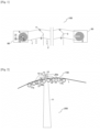
- FIG 2 shows an intermediate support 200 of the cable transport line 100 using the control method 300 according to the invention.
- the support 200 has a pylon-type structure and is equipped with a shaft 11 which provides the connection with the ground.
- a main jib 12 rests on the shaft 11 at the top of the pylon and makes it possible to support the support of the cable 1.
- the support is constituted by a balance 130, composed of a main arm 13 rotating about an axis 14.
- the axis 14 provides the connection between the arm 13 and the jib 12.
- the rotation axis 14 rests on an intermediate part 15 connected to the jib 12 via a force sensor 16, of the dynanometric axis type.
- the force sensor 16 returns an image signal of the force transmitted by the entire balance 130 in contact with the cable 1.
- the main arm 13 is connected to secondary arms 18 of the balance 130, in pivot connection along an axis 20a.
- the arms secondary 18 are connected to arms 19 of the balance 130, in pivot connection along an axis 20b, which support two rollers 21.
- the cable 1 is in point contact with the rolling band of the rollers 21.
- a tilt sensor 17a is secured to the arm 19 at the input of the balance 130 and returns an image signal of the inclination of the cable to the input of the balance 130.
- a tilt sensor 17b is secured to the arm 19 at the output of the balance 130 and returns an image signal of the inclination of the cable to the output of the balance 130 to a calculation system, not shown, configured to implement the method which is described later in the description.
- the balance 130 comprises at least one control device 22, consisting of a motor, brake and clutch assembly, which acts in direct interaction with the rotation axis 29 of at least one roller 21 in adherent contact with the cable 1.
- the control device 22 is connected to a calculation system, not shown, configured to implement the method which is described later in the description.
- the computing system may be a central processing unit comprising at least one single-core or multi-core processor.
- the computing system is a remote computer server to which the control device 22 has access by a wired connection or by a wireless connection via a communication network, such as the Internet.
- the connection to the communication network may be secure.
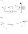
- FIG 3 shows the assembly 23 formed by the roller 21, its axis of rotation 29 in connection with the balance arm 19, the cable 1 in adherent contact with the roller 21, and the control device 22.
- the control device 22 is composed on the one hand by a motor unit 24 dedicated to providing rotational energy to the roller 21 to accelerate its rotation speed, connected to a clutch mechanism 26 to temporarily couple the motor unit 24 to the rotation receiving shaft 29.
- the motor unit 24 is of the electric type.
- the motor unit 24 and the clutch unit 26 are integral with the balance arm 19.
- the control device is composed on the other hand by a brake unit 25, dedicated to dissipating the rotational energy of the roller 21 to slow down its rotation, connected to a clutch mechanism 27 to temporarily couple the shaft 29 to the receiving shaft of the brake block 25.
- the brake block is of the electromagnetic type.
- the brake block is based on mechanical operation with direct frictional contact of the part to be slowed down.
- the brake block 25 and the clutch block 27 are integral with the balance arm 19.
- the axis 29 is integral with the roller 21 by an embedded connection 30.
- a rotating joint 31 ensures the sealing of the rotating assembly.
- a bearing 32 guides the rotating assembly, to allow the axis 29 to rotate relative to the balance arm 19.
- a rotation speed sensor 28, of the tachometric type is positioned at the end of the axis 29 and returns a signal to the calculation system configured to implement the control method 300 described later in the description.
- the control device 22 is only composed of a motor unit 24, of the electric type, dedicated to providing rotational energy to the roller 21 to accelerate its rotational speed and to dissipating the energy by reversible operation according to the principle of induction.
- the motor unit 24 is connected to a clutch mechanism 26 to temporarily couple the motor unit 24 with the rotation-receiving shaft 29.
- the motor unit 24 and the clutch unit 26 are integral with the balance arm 19.
- the shaft 29 is integral with the roller 21 by a recessed connection 30.
- a rotating joint 31 ensures the sealing of the rotational assembly.
- a bearing 32 makes it possible to guide the assembly in rotation, to allow the axis 29 to rotate relative to the balance arm 19.
- a rotation speed sensor 28, of the tachometric type is positioned at the end of the axis 29 and returns a signal to the calculation system configured to implement the control method 300 described later in the description.
- the method 300 for controlling line oscillations of a cable transport installation 100 will now be described.
- a schematic representation of the control method 300 is illustrated in FIG. figure 5 .
- the control method 300 comprises a step of generating an instruction 33 from a measurement 10, carried out in real time in a drive station 60 or by a set of force sensors 16, inclination sensors 17a, 17b, tachometer sensors 28 arranged on the balance 130 of any intermediate support 200 of the transport installation 100.
- the control method 300 comprises a step of acquiring a reference signal 33.
- the reference signal is generated by the measurement 10 of the instantaneous speed of the cable 1 at the drive pulley 6.
- the signal from the measurement 10 can, if necessary, be filtered in order to select a frequency content suitable for its use in the control method 300.
- the setpoint 33 is the average local tension ⁇ T(t) > of the cable 1 estimated from the measurements of the force sensors 16 and inclinations 17a, 17b at the level of the balance 130 of any intermediate support 200 of the transport installation 100.
- the setpoint signal 33 is generated by indirect measurement of the local tension of the cable 1 at the balance 130.
- the instruction 33 is then constructed from the time average of the image signal of the voltage T ( t ) over a given time period ⁇ t .
- the choice of the period is for example fixed by the periodicity of the vehicles passing over the installation, with the evaluation of the average of T ( t ) over an integer number of periods adapted to reflect the operating state of the installation 100.
- the final signal, resulting from the evaluation of the average voltage ⁇ T ( t ) >, can be filtered if necessary in order to select a frequency content adapted for its use in the control method 300.
- the control method 300 comprises a step of measuring a quantity of interest 39, carried out in real time by a set of force sensors 16, inclination sensors 17a, 17b, tachometer sensors 28 arranged on the balance 130 of any intermediate support 200 of the transport installation 100.
- the quantity of interest 39 is the rotation speed of at least one roller 21 of the balance 130, measured by a tachometric sensor 28 arranged on the rotation axis 29.
- the quantity of interest 39 is the instantaneous local voltage T ( t ) of the cable 1, estimated from the sensor measurements. of effort 16 and inclinations 17a 17b at the level of the balance 130 of any intermediate support 200 of the transport installation 100.
- the control method 300 comprises a step of comparison, by a comparator 34, of a setpoint quantity 33 and the quantity of interest 39, which returns the difference 35.
- the control method 300 comprises a comparison step between the setpoint signal 33 and the measurement signal 39 by a comparator 34 which calculates the absolute difference between the two signals.
- the signal 33 is established by the measurement 10 of the translation speed of the cable 1 at the drive pulley 6.
- the objective of the comparison step is to detect when an oscillation of the cable, located at the span 400 adjacent to the intermediate support 200 and equipped with the balance 130 where the roller 21 is located on which the measurement 39 of the instantaneous translation speed of the cable 1 is carried out by the sensor 28, is triggered by evaluation of the difference between the speed of the cable 1 commanded at the drive pulley 6 and that effective on the line at the intermediate support 200 adjacent to the span 400 likely to present a pumping phenomenon.
- the signal 33 is established by estimating the average ⁇ T(t) >.
- the objective of the comparison step is then to detect when an oscillation of the cable, located at the cable span 400 adjacent to the intermediate support 200 and equipped with the balance 130 where the roller 21 on which the indirect measurement 39 of the local tension of the cable 1 is carried out, is triggered by evaluating the difference between the average tension ⁇ T(t) > and the instantaneous one at the intermediate support 200 adjacent to the span 400 likely to present a pumping phenomenon.
- Signal 35 comes from comparator 34 and gives an image of the difference between the setpoint quantity 33 and the measurement 39 taken at the output of the control device 22.
- the control method 300 includes a correction step by a regulator 36 which delivers a corrected instruction 37 based on the deviation 35.
- the control method 300 comprises a correction step which delivers a corrected instruction 37 then given at the input of the control device 22 by a proportional, integral and derivative (PID) regulator 36, well known to those skilled in the art. Adjusting the gains of the regulator 36 makes it possible to satisfy the various criteria of speed, stability, precision and robustness on the control of the target quantity of the setpoint 33.
- PID proportional, integral and derivative
- control device 22 which receives the corrected speed instruction 37 from the regulator 36, is composed of at least one electric motor unit 24 temporarily connected by a coupling mechanism 26 to the rotation axis 29 of at least one roller 21 of the balance 130 of any intermediate support 200 of the transport installation 100.
- the control method 300 comprises a step of applying the corrected instruction 37 to the control device 22, of at least one roller 21 of the balance 130, carried out as long as the difference 35 from the comparator 34 is greater than a threshold value (VS); otherwise the corrected instruction 37 is not applied at the input of the control device 22.
- a threshold value VS
- the control method 300 comprises a step during which the corrected instruction 37 is not applied to the control device 22 of at least one roller 21 of the balance 130, a temporary coupling mechanism 26, 27 disengaging the motor unit 24 or brake 25 from the rotation axis 29 of the roller 21 of the balance 130, such that the roller 21 is free to rotate in adherent contact with the mobile cable 1.
- the control method 300 comprises a step during which the corrected instruction 37 is applied to the control device 22 of at least one roller 21 of the balance 130, a temporary coupling mechanism 26, 27 engaging the motor unit 24 or brake unit 25 to the rotation axis 29 of the roller 21 of the balance 130, such that the roller 21 is controlled in rotation and locally modifies the speed of the mobile cable 1 with which it is in adherent contact.
- the regulator 36 has a threshold (VS) on the minimum value of the signal 35, below which the control loop of the control method 300 is not activated.
- VS threshold
- the mechanisms 26, 27 of the control device 22 ensure the disengagement of the motor unit 24 and brake 25 of the rotation axis 29 of the roller 21.
- the threshold value (VS) of the signal 35 is reached, the control loop of the control method 300 is activated.
- the mechanisms 26, 27 of the control device 22 ensures the clutch of the engine block 24 or brake 25 on the axis of rotation 29 of the roller 21.
- the purpose of the clutch is to reduce the dissipation of electromagnetic and mechanical energy which would be caused by the rotation of the axis of the motor and/or brake blocks, in the continuity of the axis 29, when no control order is given to the motor 24 or brake 25 block.
- the control method 300 comprises a step of applying the corrected instruction 37 to the input of a control device 22 which acts on the rotation of at least one roller 21 of the balance 130 in adhesion with the mobile cable 1.
- the corrected instruction 37 is given to the control device 22 in the form of a rotation speed.
- an instruction 37 corresponding to an increase or a reduction in the rotation speed of the roller 21 is given to the control device 22.
- the control method 300 comprises a step of modifying the rotation speed of at least one roller 21 of the balance 130, by temporarily coupling a motor unit 24 or a brake unit 25, aimed at reducing the oscillation of the mobile cable 1 by limiting its variations in speed or line tension.
- the control method 300 comprises a step of accelerating the rotational movement of the roller 21 by engaging the motor unit 24, via the mechanism 26, on the rotation axis 29.
- the motor unit 24 then provides a supply of mechanical energy to the rotational movement of the roller 21 in contact with the cable 1.
- the brake unit 25 then remains disengaged from the rotation axis 29, via the mechanism 27.
- the control method 300 comprises a step of decelerating the rotational movement of the roller 21 by engaging the brake block 25 on the rotation axis 29, via the mechanism 27.
- the brake block 25 then dissipates the mechanical energy from the point of view of the rotation of the roller 21 in contact with the cable 1.
- the motor block 24 then remains disengaged from the rotation axis 29, via the mechanism 26.
- the engine block 24 also performs the function of the brake block 25 according to a reversible operating mode, between the engine and the alternator, illustrated by the figure 4 . According to this embodiment, recovery of electrical energy from alternator operation is possible, with temporary storage, and subsequent use during the engine operating phases of the control device 22.
- FIG. 6 illustrates a span 400 of the line of the transport installation 100 delimited by an intermediate support 201 at the entrance to span 400 and an intermediate support 202 at the exit of span 400.
- the illustrated configuration corresponds to an operating mode without oscillations of the cable 1, which occupies its nominal position 1a when the translation speed of the cable V A at the support 201 is equal to that V B at the support 202, and equal to the speed of the cable V 0 set at the drive pulley 6.
- the control method 300 does not act on the speed of rotation of the rollers 21, in contact with the cable 1, via the control device 22.
- the rollers 21 of the balancers 130 remain free to rotate.
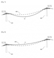
- FIG. 7 illustrates a span 400 of the line of the transport installation 100 delimited by an intermediate support 201 at the entrance to span 400 and an intermediate support 202 at the exit of span 400.
- the illustrated configuration corresponds to an operating mode with a low oscillation of the cable 1, which occupies its low position 1b when the translation speed of the cable V A at the support 201 is greater than that V B at the support 202, V B being equal to the speed of the cable V 0 set at the drive pulley 6.
- the control method 300 acts by reducing the rotation speed of at least one roller 21 of the balance 130 of the support 201, in contact with the cable 1, by means of the brake block of the control device 22.
- FIG. 8 illustrates a span 400 of the line of the transport installation 100 delimited by an intermediate support 201 at the entrance to span 400 and an intermediate support 202 at the exit of span 400.
- the illustrated configuration corresponds to an operating mode with a high oscillation of the cable 1, which occupies its high position 1c when the translation speed of the cable V A at the support 201 is lower than that V B at the support 202, V B being equal to the speed of the cable V 0 set at the drive pulley 6.
- the control method 300 acts by increasing the rotation speed of at least one roller 21 of the balance 130 of the support 201, in contact with the cable 1, via the motor unit of the control device 22.
- control method 300 and of the device configured to implement it is developed for a mobile cable transport system. equipped with several vehicles distributed along a single cable loop and to which they are attached. The principle detailed in this description nevertheless remains valid for back-and-forth and continuous movement devices, equipped with a single or several vehicles on each track, with one or more mobile and/or fixed cables.
Landscapes
- Engineering & Computer Science (AREA)
- Mechanical Engineering (AREA)
- Transportation (AREA)
- Health & Medical Sciences (AREA)
- Heart & Thoracic Surgery (AREA)
- Biomedical Technology (AREA)
- General Health & Medical Sciences (AREA)
- Tension Adjustment In Filamentary Materials (AREA)
Applications Claiming Priority (1)
| Application Number | Priority Date | Filing Date | Title |
|---|---|---|---|
| FR2306431A FR3150176A1 (fr) | 2023-06-21 | 2023-06-21 | Procédé de contrôle des oscillations de ligne d’une installation de transport de véhicules par câbles et dispositif configuré pour mettre en œuvre le procédé. |
Publications (1)
| Publication Number | Publication Date |
|---|---|
| EP4480778A1 true EP4480778A1 (de) | 2024-12-25 |
Family
ID=88207589
Family Applications (1)
| Application Number | Title | Priority Date | Filing Date |
|---|---|---|---|
| EP24183245.0A Pending EP4480778A1 (de) | 2023-06-21 | 2024-06-20 | Verfahren zur steuerung von leitungsschwingungen einer seilbahnanlage durch kabel und zur durchführung des verfahrens konfigurierte vorrichtung |
Country Status (2)
| Country | Link |
|---|---|
| EP (1) | EP4480778A1 (de) |
| FR (1) | FR3150176A1 (de) |
Citations (4)
| Publication number | Priority date | Publication date | Assignee | Title |
|---|---|---|---|---|
| EP0015211A1 (de) * | 1979-02-27 | 1980-09-03 | Compagnie Minière de l'Ogooué COMILOG | Vorrichtung zur Geschwindigkeitsstabilisierung einer Seilförderanlage |
| EP2990292A1 (de) * | 2014-09-01 | 2016-03-02 | Poma | Anlage und verfahren zum transport über seilbahn |
| EP3620340A1 (de) * | 2018-09-10 | 2020-03-11 | Bartholet Maschinenbau AG | Luftseilbahnanlage, verfahren zum betrieb einer luftseilbahnanlage sowie seilrolle für eine luftseilbahnanlage |
| FR3108185A1 (fr) | 2020-03-11 | 2021-09-17 | Bureau des Etudes de Câbles | Procédé de contrôle d’une installation de transport de véhicules par un câble à mouvement continu et dispositif configuré pour mettre en œuvre le procédé. |
-
2023
- 2023-06-21 FR FR2306431A patent/FR3150176A1/fr active Pending
-
2024
- 2024-06-20 EP EP24183245.0A patent/EP4480778A1/de active Pending
Patent Citations (4)
| Publication number | Priority date | Publication date | Assignee | Title |
|---|---|---|---|---|
| EP0015211A1 (de) * | 1979-02-27 | 1980-09-03 | Compagnie Minière de l'Ogooué COMILOG | Vorrichtung zur Geschwindigkeitsstabilisierung einer Seilförderanlage |
| EP2990292A1 (de) * | 2014-09-01 | 2016-03-02 | Poma | Anlage und verfahren zum transport über seilbahn |
| EP3620340A1 (de) * | 2018-09-10 | 2020-03-11 | Bartholet Maschinenbau AG | Luftseilbahnanlage, verfahren zum betrieb einer luftseilbahnanlage sowie seilrolle für eine luftseilbahnanlage |
| FR3108185A1 (fr) | 2020-03-11 | 2021-09-17 | Bureau des Etudes de Câbles | Procédé de contrôle d’une installation de transport de véhicules par un câble à mouvement continu et dispositif configuré pour mettre en œuvre le procédé. |
Also Published As
| Publication number | Publication date |
|---|---|
| FR3150176A1 (fr) | 2024-12-27 |
Similar Documents
| Publication | Publication Date | Title |
|---|---|---|
| FR2670451A1 (fr) | Telecabine ou telesiege debrayage a deux boucles de cable. | |
| FR2578496A1 (fr) | Systeme de commande de deceleration | |
| EP2389306B1 (de) | Verfahren zur überwachung der vorwärtsbewegung eines fahrzeuges in einer seilbahnanlage | |
| FR2698344A1 (fr) | Dispositif de régulation du transfert d'une charge suspendue. | |
| CA2960074A1 (fr) | Funiculaire entraine par un cable en boucle fermee a deux troncons tracteurs et procede de commande d'un tel funiculaire | |
| EP0378489A1 (de) | Seiltransporteinrichtung mit kontrollierter Zugspannung | |
| FR2583363A1 (fr) | Installation de transport a cable aerien a espacement reduit des cabines en station | |
| EP4480778A1 (de) | Verfahren zur steuerung von leitungsschwingungen einer seilbahnanlage durch kabel und zur durchführung des verfahrens konfigurierte vorrichtung | |
| EP0015211B1 (de) | Vorrichtung zur Geschwindigkeitsstabilisierung einer Seilförderanlage | |
| FR2950039A1 (fr) | Attelage avec organes d'attache integres dans la bande roulement a friction, train et convoyeur. | |
| EP3878707B1 (de) | Verfahren zur kontrolle einer fahrzeug-transportanlage mittels eines sich kontinuierlich bewegenden kabels, und vorrichtung, die für die durchführung des verfahrens konfiguriert ist | |
| FR2708920A1 (fr) | Procédé de contrôle de balancement d'une charge pendulaire et dispositif de mise en Óoeuvre du procédé. | |
| EP2086810B1 (de) | Verfahren zur simulation des bremsens eines kabeltransportsystems, verfahren zur diagnose des bremsens des systems und steuervorrichtung für das system | |
| EP0611211B1 (de) | Kontroll- und Steuersystem für die Geschwindigkeit einer bewegten, pendelnden Ladung und Hebevorrichtung mit einem solchen System | |
| FR2754229A1 (fr) | Procede et dispositif pour controler le deplacement d'une cabine le long d'une ligne telepherique et application a un systeme de transport en commun | |
| EP0094703B1 (de) | Tragvorrichtung und Kontrolleinrichtung für die Synchronisierung der Bewegung einer Laufbrücke | |
| FR3013298A1 (fr) | Dispositif d’attache d’un vehicule a un dispositif d’entrainement d’une ligne de transport | |
| FR2937939A1 (fr) | Installation double monocables a voie large | |
| FR3025476A1 (fr) | Funiculaire entraine par un cable a deux troncons tracteurs et procede de commande d'un tel funiculaire | |
| EP4228946B1 (de) | Transportsystem, auf dem ein fahrzeug fährt, und verfahren zur steuerung solch eines fahrzeugs | |
| FR2926803A1 (fr) | Economie d'energie par suppression du contrepoids d'un ascenseur pour machineries stationnaires avec un controle de positionnement et de vitesse | |
| FR2743058A1 (fr) | Dispositif d'antipatinage pour un chariot d'engin de levage | |
| WO2025003610A1 (fr) | Procédé de contrôle d'un pantographe comprenant un actionneur électrique, pantographe et véhicule ferroviaire mettant en œuvre un tel procédé | |
| WO2025026890A1 (fr) | Système de levage d'un colis, en particulier pour le levage d'un colis en présence d'un mouvement relatif dû à la houle | |
| FR2920020A1 (fr) | Procede et dispositif de levage d'une masse par une pluralite de colonnes de levage. |
Legal Events
| Date | Code | Title | Description |
|---|---|---|---|
| PUAI | Public reference made under article 153(3) epc to a published international application that has entered the european phase |
Free format text: ORIGINAL CODE: 0009012 |
|
| STAA | Information on the status of an ep patent application or granted ep patent |
Free format text: STATUS: THE APPLICATION HAS BEEN PUBLISHED |
|
| AK | Designated contracting states |
Kind code of ref document: A1 Designated state(s): AL AT BE BG CH CY CZ DE DK EE ES FI FR GB GR HR HU IE IS IT LI LT LU LV MC ME MK MT NL NO PL PT RO RS SE SI SK SM TR |
|
| STAA | Information on the status of an ep patent application or granted ep patent |
Free format text: STATUS: REQUEST FOR EXAMINATION WAS MADE |
|
| 17P | Request for examination filed |
Effective date: 20250207 |