EP4480742A1 - Power supply system, non-transitory computer readable medium, and power management method - Google Patents
Power supply system, non-transitory computer readable medium, and power management method Download PDFInfo
- Publication number
- EP4480742A1 EP4480742A1 EP24177622.8A EP24177622A EP4480742A1 EP 4480742 A1 EP4480742 A1 EP 4480742A1 EP 24177622 A EP24177622 A EP 24177622A EP 4480742 A1 EP4480742 A1 EP 4480742A1
- Authority
- EP
- European Patent Office
- Prior art keywords
- power
- amount
- power storage
- electric vehicle
- storage apparatus
- Prior art date
- Legal status (The legal status is an assumption and is not a legal conclusion. Google has not performed a legal analysis and makes no representation as to the accuracy of the status listed.)
- Pending
Links
Images


Classifications
-
- B—PERFORMING OPERATIONS; TRANSPORTING
- B60—VEHICLES IN GENERAL
- B60L—PROPULSION OF ELECTRICALLY-PROPELLED VEHICLES; SUPPLYING ELECTRIC POWER FOR AUXILIARY EQUIPMENT OF ELECTRICALLY-PROPELLED VEHICLES; ELECTRODYNAMIC BRAKE SYSTEMS FOR VEHICLES IN GENERAL; MAGNETIC SUSPENSION OR LEVITATION FOR VEHICLES; MONITORING OPERATING VARIABLES OF ELECTRICALLY-PROPELLED VEHICLES; ELECTRIC SAFETY DEVICES FOR ELECTRICALLY-PROPELLED VEHICLES
- B60L53/00—Methods of charging batteries, specially adapted for electric vehicles; Charging stations or on-board charging equipment therefor; Exchange of energy storage elements in electric vehicles
- B60L53/50—Charging stations characterised by energy-storage or power-generation means
- B60L53/53—Batteries
-
- H—ELECTRICITY
- H02—GENERATION; CONVERSION OR DISTRIBUTION OF ELECTRIC POWER
- H02J—ELECTRIC POWER NETWORKS; CIRCUIT ARRANGEMENTS OR SYSTEMS FOR SUPPLYING OR DISTRIBUTING ELECTRIC POWER; SYSTEMS FOR STORING ELECTRIC ENERGY
- H02J7/00—Circuit arrangements for charging or discharging batteries or for supplying loads from batteries
- H02J7/34—Parallel operation in networks using both storage and other DC sources, e.g. providing buffering
- H02J7/35—Parallel operation in networks using both storage and other DC sources, e.g. providing buffering with light sensitive cells
-
- H—ELECTRICITY
- H02—GENERATION; CONVERSION OR DISTRIBUTION OF ELECTRIC POWER
- H02J—ELECTRIC POWER NETWORKS; CIRCUIT ARRANGEMENTS OR SYSTEMS FOR SUPPLYING OR DISTRIBUTING ELECTRIC POWER; SYSTEMS FOR STORING ELECTRIC ENERGY
- H02J3/00—Circuit arrangements for AC mains or AC distribution networks
- H02J3/38—Arrangements for feeding a single network from two or more generators or sources in parallel; Arrangements for feeding already energised networks from additional generators or sources in parallel
-
- B—PERFORMING OPERATIONS; TRANSPORTING
- B60—VEHICLES IN GENERAL
- B60L—PROPULSION OF ELECTRICALLY-PROPELLED VEHICLES; SUPPLYING ELECTRIC POWER FOR AUXILIARY EQUIPMENT OF ELECTRICALLY-PROPELLED VEHICLES; ELECTRODYNAMIC BRAKE SYSTEMS FOR VEHICLES IN GENERAL; MAGNETIC SUSPENSION OR LEVITATION FOR VEHICLES; MONITORING OPERATING VARIABLES OF ELECTRICALLY-PROPELLED VEHICLES; ELECTRIC SAFETY DEVICES FOR ELECTRICALLY-PROPELLED VEHICLES
- B60L50/00—Electric propulsion with power supplied within the vehicle
- B60L50/50—Electric propulsion with power supplied within the vehicle using propulsion power supplied by batteries or fuel cells
- B60L50/60—Electric propulsion with power supplied within the vehicle using propulsion power supplied by batteries or fuel cells using power supplied by batteries
-
- B—PERFORMING OPERATIONS; TRANSPORTING
- B60—VEHICLES IN GENERAL
- B60L—PROPULSION OF ELECTRICALLY-PROPELLED VEHICLES; SUPPLYING ELECTRIC POWER FOR AUXILIARY EQUIPMENT OF ELECTRICALLY-PROPELLED VEHICLES; ELECTRODYNAMIC BRAKE SYSTEMS FOR VEHICLES IN GENERAL; MAGNETIC SUSPENSION OR LEVITATION FOR VEHICLES; MONITORING OPERATING VARIABLES OF ELECTRICALLY-PROPELLED VEHICLES; ELECTRIC SAFETY DEVICES FOR ELECTRICALLY-PROPELLED VEHICLES
- B60L53/00—Methods of charging batteries, specially adapted for electric vehicles; Charging stations or on-board charging equipment therefor; Exchange of energy storage elements in electric vehicles
- B60L53/50—Charging stations characterised by energy-storage or power-generation means
- B60L53/51—Photovoltaic means
-
- B—PERFORMING OPERATIONS; TRANSPORTING
- B60—VEHICLES IN GENERAL
- B60L—PROPULSION OF ELECTRICALLY-PROPELLED VEHICLES; SUPPLYING ELECTRIC POWER FOR AUXILIARY EQUIPMENT OF ELECTRICALLY-PROPELLED VEHICLES; ELECTRODYNAMIC BRAKE SYSTEMS FOR VEHICLES IN GENERAL; MAGNETIC SUSPENSION OR LEVITATION FOR VEHICLES; MONITORING OPERATING VARIABLES OF ELECTRICALLY-PROPELLED VEHICLES; ELECTRIC SAFETY DEVICES FOR ELECTRICALLY-PROPELLED VEHICLES
- B60L53/00—Methods of charging batteries, specially adapted for electric vehicles; Charging stations or on-board charging equipment therefor; Exchange of energy storage elements in electric vehicles
- B60L53/60—Monitoring or controlling charging stations
-
- B—PERFORMING OPERATIONS; TRANSPORTING
- B60—VEHICLES IN GENERAL
- B60L—PROPULSION OF ELECTRICALLY-PROPELLED VEHICLES; SUPPLYING ELECTRIC POWER FOR AUXILIARY EQUIPMENT OF ELECTRICALLY-PROPELLED VEHICLES; ELECTRODYNAMIC BRAKE SYSTEMS FOR VEHICLES IN GENERAL; MAGNETIC SUSPENSION OR LEVITATION FOR VEHICLES; MONITORING OPERATING VARIABLES OF ELECTRICALLY-PROPELLED VEHICLES; ELECTRIC SAFETY DEVICES FOR ELECTRICALLY-PROPELLED VEHICLES
- B60L53/00—Methods of charging batteries, specially adapted for electric vehicles; Charging stations or on-board charging equipment therefor; Exchange of energy storage elements in electric vehicles
- B60L53/60—Monitoring or controlling charging stations
- B60L53/62—Monitoring or controlling charging stations in response to charging parameters, e.g. current, voltage or electrical charge
-
- B—PERFORMING OPERATIONS; TRANSPORTING
- B60—VEHICLES IN GENERAL
- B60L—PROPULSION OF ELECTRICALLY-PROPELLED VEHICLES; SUPPLYING ELECTRIC POWER FOR AUXILIARY EQUIPMENT OF ELECTRICALLY-PROPELLED VEHICLES; ELECTRODYNAMIC BRAKE SYSTEMS FOR VEHICLES IN GENERAL; MAGNETIC SUSPENSION OR LEVITATION FOR VEHICLES; MONITORING OPERATING VARIABLES OF ELECTRICALLY-PROPELLED VEHICLES; ELECTRIC SAFETY DEVICES FOR ELECTRICALLY-PROPELLED VEHICLES
- B60L55/00—Arrangements for supplying energy stored within a vehicle to a power network, i.e. vehicle-to-grid [V2G] arrangements
-
- B—PERFORMING OPERATIONS; TRANSPORTING
- B60—VEHICLES IN GENERAL
- B60L—PROPULSION OF ELECTRICALLY-PROPELLED VEHICLES; SUPPLYING ELECTRIC POWER FOR AUXILIARY EQUIPMENT OF ELECTRICALLY-PROPELLED VEHICLES; ELECTRODYNAMIC BRAKE SYSTEMS FOR VEHICLES IN GENERAL; MAGNETIC SUSPENSION OR LEVITATION FOR VEHICLES; MONITORING OPERATING VARIABLES OF ELECTRICALLY-PROPELLED VEHICLES; ELECTRIC SAFETY DEVICES FOR ELECTRICALLY-PROPELLED VEHICLES
- B60L58/00—Methods or circuit arrangements for monitoring or controlling batteries or fuel cells, specially adapted for electric vehicles
- B60L58/10—Methods or circuit arrangements for monitoring or controlling batteries or fuel cells, specially adapted for electric vehicles for monitoring or controlling batteries
- B60L58/12—Methods or circuit arrangements for monitoring or controlling batteries or fuel cells, specially adapted for electric vehicles for monitoring or controlling batteries responding to state of charge [SoC]
- B60L58/13—Maintaining the SoC within a determined range
-
- B—PERFORMING OPERATIONS; TRANSPORTING
- B60—VEHICLES IN GENERAL
- B60L—PROPULSION OF ELECTRICALLY-PROPELLED VEHICLES; SUPPLYING ELECTRIC POWER FOR AUXILIARY EQUIPMENT OF ELECTRICALLY-PROPELLED VEHICLES; ELECTRODYNAMIC BRAKE SYSTEMS FOR VEHICLES IN GENERAL; MAGNETIC SUSPENSION OR LEVITATION FOR VEHICLES; MONITORING OPERATING VARIABLES OF ELECTRICALLY-PROPELLED VEHICLES; ELECTRIC SAFETY DEVICES FOR ELECTRICALLY-PROPELLED VEHICLES
- B60L58/00—Methods or circuit arrangements for monitoring or controlling batteries or fuel cells, specially adapted for electric vehicles
- B60L58/10—Methods or circuit arrangements for monitoring or controlling batteries or fuel cells, specially adapted for electric vehicles for monitoring or controlling batteries
- B60L58/12—Methods or circuit arrangements for monitoring or controlling batteries or fuel cells, specially adapted for electric vehicles for monitoring or controlling batteries responding to state of charge [SoC]
- B60L58/15—Preventing overcharging
-
- B—PERFORMING OPERATIONS; TRANSPORTING
- B60—VEHICLES IN GENERAL
- B60L—PROPULSION OF ELECTRICALLY-PROPELLED VEHICLES; SUPPLYING ELECTRIC POWER FOR AUXILIARY EQUIPMENT OF ELECTRICALLY-PROPELLED VEHICLES; ELECTRODYNAMIC BRAKE SYSTEMS FOR VEHICLES IN GENERAL; MAGNETIC SUSPENSION OR LEVITATION FOR VEHICLES; MONITORING OPERATING VARIABLES OF ELECTRICALLY-PROPELLED VEHICLES; ELECTRIC SAFETY DEVICES FOR ELECTRICALLY-PROPELLED VEHICLES
- B60L58/00—Methods or circuit arrangements for monitoring or controlling batteries or fuel cells, specially adapted for electric vehicles
- B60L58/10—Methods or circuit arrangements for monitoring or controlling batteries or fuel cells, specially adapted for electric vehicles for monitoring or controlling batteries
- B60L58/16—Methods or circuit arrangements for monitoring or controlling batteries or fuel cells, specially adapted for electric vehicles for monitoring or controlling batteries responding to battery ageing, e.g. to the number of charging cycles or the state of health [SoH]
-
- G—PHYSICS
- G06—COMPUTING OR CALCULATING; COUNTING
- G06Q—INFORMATION AND COMMUNICATION TECHNOLOGY [ICT] SPECIALLY ADAPTED FOR ADMINISTRATIVE, COMMERCIAL, FINANCIAL, MANAGERIAL OR SUPERVISORY PURPOSES; SYSTEMS OR METHODS SPECIALLY ADAPTED FOR ADMINISTRATIVE, COMMERCIAL, FINANCIAL, MANAGERIAL OR SUPERVISORY PURPOSES, NOT OTHERWISE PROVIDED FOR
- G06Q50/00—Information and communication technology [ICT] specially adapted for implementation of business processes of specific business sectors, e.g. utilities or tourism
- G06Q50/06—Energy or water supply
-
- H—ELECTRICITY
- H02—GENERATION; CONVERSION OR DISTRIBUTION OF ELECTRIC POWER
- H02J—ELECTRIC POWER NETWORKS; CIRCUIT ARRANGEMENTS OR SYSTEMS FOR SUPPLYING OR DISTRIBUTING ELECTRIC POWER; SYSTEMS FOR STORING ELECTRIC ENERGY
- H02J3/00—Circuit arrangements for AC mains or AC distribution networks
- H02J3/003—Load forecast, e.g. methods or systems for forecasting future load demand
-
- H—ELECTRICITY
- H02—GENERATION; CONVERSION OR DISTRIBUTION OF ELECTRIC POWER
- H02J—ELECTRIC POWER NETWORKS; CIRCUIT ARRANGEMENTS OR SYSTEMS FOR SUPPLYING OR DISTRIBUTING ELECTRIC POWER; SYSTEMS FOR STORING ELECTRIC ENERGY
- H02J3/00—Circuit arrangements for AC mains or AC distribution networks
- H02J3/004—Generation forecast, e.g. methods or systems for forecasting future energy generation
-
- H—ELECTRICITY
- H02—GENERATION; CONVERSION OR DISTRIBUTION OF ELECTRIC POWER
- H02J—ELECTRIC POWER NETWORKS; CIRCUIT ARRANGEMENTS OR SYSTEMS FOR SUPPLYING OR DISTRIBUTING ELECTRIC POWER; SYSTEMS FOR STORING ELECTRIC ENERGY
- H02J3/00—Circuit arrangements for AC mains or AC distribution networks
- H02J3/28—Arrangements for balancing of the load in networks by storage of energy
- H02J3/32—Arrangements for balancing of the load in networks by storage of energy using batteries or super capacitors with converting means
- H02J3/322—Arrangements for balancing of the load in networks by storage of energy using batteries or super capacitors with converting means the battery being on-board an electric or hybrid vehicle, e.g. vehicle to grid arrangements [V2G], power aggregation, use of the battery for network load balancing, coordinated or cooperative battery charging
-
- H—ELECTRICITY
- H02—GENERATION; CONVERSION OR DISTRIBUTION OF ELECTRIC POWER
- H02J—ELECTRIC POWER NETWORKS; CIRCUIT ARRANGEMENTS OR SYSTEMS FOR SUPPLYING OR DISTRIBUTING ELECTRIC POWER; SYSTEMS FOR STORING ELECTRIC ENERGY
- H02J7/00—Circuit arrangements for charging or discharging batteries or for supplying loads from batteries
- H02J7/80—Circuit arrangements for charging or discharging batteries or for supplying loads from batteries including monitoring or indicating arrangements
- H02J7/82—Control of state of charge [SOC]
-
- H—ELECTRICITY
- H02—GENERATION; CONVERSION OR DISTRIBUTION OF ELECTRIC POWER
- H02J—ELECTRIC POWER NETWORKS; CIRCUIT ARRANGEMENTS OR SYSTEMS FOR SUPPLYING OR DISTRIBUTING ELECTRIC POWER; SYSTEMS FOR STORING ELECTRIC ENERGY
- H02J7/00—Circuit arrangements for charging or discharging batteries or for supplying loads from batteries
- H02J7/80—Circuit arrangements for charging or discharging batteries or for supplying loads from batteries including monitoring or indicating arrangements
- H02J7/82—Control of state of charge [SOC]
- H02J7/825—Detection of fully charged condition
-
- H—ELECTRICITY
- H02—GENERATION; CONVERSION OR DISTRIBUTION OF ELECTRIC POWER
- H02J—ELECTRIC POWER NETWORKS; CIRCUIT ARRANGEMENTS OR SYSTEMS FOR SUPPLYING OR DISTRIBUTING ELECTRIC POWER; SYSTEMS FOR STORING ELECTRIC ENERGY
- H02J7/00—Circuit arrangements for charging or discharging batteries or for supplying loads from batteries
- H02J7/855—Circuit arrangements for charging or discharging batteries or for supplying loads from batteries with circuits adapted for supplying loads from the battery
-
- H—ELECTRICITY
- H02—GENERATION; CONVERSION OR DISTRIBUTION OF ELECTRIC POWER
- H02J—ELECTRIC POWER NETWORKS; CIRCUIT ARRANGEMENTS OR SYSTEMS FOR SUPPLYING OR DISTRIBUTING ELECTRIC POWER; SYSTEMS FOR STORING ELECTRIC ENERGY
- H02J7/00—Circuit arrangements for charging or discharging batteries or for supplying loads from batteries
- H02J7/90—Regulation of charging or discharging current or voltage
- H02J7/933—Regulation of charging or discharging current or voltage the cycle being controlled or terminated in response to electric parameters
-
- B—PERFORMING OPERATIONS; TRANSPORTING
- B60—VEHICLES IN GENERAL
- B60L—PROPULSION OF ELECTRICALLY-PROPELLED VEHICLES; SUPPLYING ELECTRIC POWER FOR AUXILIARY EQUIPMENT OF ELECTRICALLY-PROPELLED VEHICLES; ELECTRODYNAMIC BRAKE SYSTEMS FOR VEHICLES IN GENERAL; MAGNETIC SUSPENSION OR LEVITATION FOR VEHICLES; MONITORING OPERATING VARIABLES OF ELECTRICALLY-PROPELLED VEHICLES; ELECTRIC SAFETY DEVICES FOR ELECTRICALLY-PROPELLED VEHICLES
- B60L2260/00—Operating Modes
- B60L2260/40—Control modes
- B60L2260/50—Control modes by future state prediction
-
- B—PERFORMING OPERATIONS; TRANSPORTING
- B60—VEHICLES IN GENERAL
- B60L—PROPULSION OF ELECTRICALLY-PROPELLED VEHICLES; SUPPLYING ELECTRIC POWER FOR AUXILIARY EQUIPMENT OF ELECTRICALLY-PROPELLED VEHICLES; ELECTRODYNAMIC BRAKE SYSTEMS FOR VEHICLES IN GENERAL; MAGNETIC SUSPENSION OR LEVITATION FOR VEHICLES; MONITORING OPERATING VARIABLES OF ELECTRICALLY-PROPELLED VEHICLES; ELECTRIC SAFETY DEVICES FOR ELECTRICALLY-PROPELLED VEHICLES
- B60L2260/00—Operating Modes
- B60L2260/40—Control modes
- B60L2260/50—Control modes by future state prediction
- B60L2260/52—Control modes by future state prediction drive range estimation, e.g. of estimation of available travel distance
-
- H—ELECTRICITY
- H02—GENERATION; CONVERSION OR DISTRIBUTION OF ELECTRIC POWER
- H02J—ELECTRIC POWER NETWORKS; CIRCUIT ARRANGEMENTS OR SYSTEMS FOR SUPPLYING OR DISTRIBUTING ELECTRIC POWER; SYSTEMS FOR STORING ELECTRIC ENERGY
- H02J2101/00—Supply or distribution of decentralised, dispersed or local electric power generation
- H02J2101/20—Dispersed power generation using renewable energy sources
- H02J2101/22—Solar energy
- H02J2101/24—Photovoltaics
-
- H—ELECTRICITY
- H02—GENERATION; CONVERSION OR DISTRIBUTION OF ELECTRIC POWER
- H02J—ELECTRIC POWER NETWORKS; CIRCUIT ARRANGEMENTS OR SYSTEMS FOR SUPPLYING OR DISTRIBUTING ELECTRIC POWER; SYSTEMS FOR STORING ELECTRIC ENERGY
- H02J2105/00—Networks for supplying or distributing electric power characterised by their spatial reach or by the load
- H02J2105/30—Networks for supplying or distributing electric power characterised by their spatial reach or by the load the load networks being external to vehicles, i.e. exchanging power with vehicles
-
- Y—GENERAL TAGGING OF NEW TECHNOLOGICAL DEVELOPMENTS; GENERAL TAGGING OF CROSS-SECTIONAL TECHNOLOGIES SPANNING OVER SEVERAL SECTIONS OF THE IPC; TECHNICAL SUBJECTS COVERED BY FORMER USPC CROSS-REFERENCE ART COLLECTIONS [XRACs] AND DIGESTS
- Y02—TECHNOLOGIES OR APPLICATIONS FOR MITIGATION OR ADAPTATION AGAINST CLIMATE CHANGE
- Y02E—REDUCTION OF GREENHOUSE GAS [GHG] EMISSIONS, RELATED TO ENERGY GENERATION, TRANSMISSION OR DISTRIBUTION
- Y02E10/00—Energy generation through renewable energy sources
- Y02E10/50—Photovoltaic [PV] energy
-
- Y—GENERAL TAGGING OF NEW TECHNOLOGICAL DEVELOPMENTS; GENERAL TAGGING OF CROSS-SECTIONAL TECHNOLOGIES SPANNING OVER SEVERAL SECTIONS OF THE IPC; TECHNICAL SUBJECTS COVERED BY FORMER USPC CROSS-REFERENCE ART COLLECTIONS [XRACs] AND DIGESTS
- Y02—TECHNOLOGIES OR APPLICATIONS FOR MITIGATION OR ADAPTATION AGAINST CLIMATE CHANGE
- Y02E—REDUCTION OF GREENHOUSE GAS [GHG] EMISSIONS, RELATED TO ENERGY GENERATION, TRANSMISSION OR DISTRIBUTION
- Y02E60/00—Enabling technologies; Technologies with a potential or indirect contribution to GHG emissions mitigation
- Y02E60/10—Energy storage using batteries
-
- Y—GENERAL TAGGING OF NEW TECHNOLOGICAL DEVELOPMENTS; GENERAL TAGGING OF CROSS-SECTIONAL TECHNOLOGIES SPANNING OVER SEVERAL SECTIONS OF THE IPC; TECHNICAL SUBJECTS COVERED BY FORMER USPC CROSS-REFERENCE ART COLLECTIONS [XRACs] AND DIGESTS
- Y02—TECHNOLOGIES OR APPLICATIONS FOR MITIGATION OR ADAPTATION AGAINST CLIMATE CHANGE
- Y02T—CLIMATE CHANGE MITIGATION TECHNOLOGIES RELATED TO TRANSPORTATION
- Y02T10/00—Road transport of goods or passengers
- Y02T10/60—Other road transportation technologies with climate change mitigation effect
- Y02T10/7072—Electromobility specific charging systems or methods for batteries, ultracapacitors, supercapacitors or double-layer capacitors
-
- Y—GENERAL TAGGING OF NEW TECHNOLOGICAL DEVELOPMENTS; GENERAL TAGGING OF CROSS-SECTIONAL TECHNOLOGIES SPANNING OVER SEVERAL SECTIONS OF THE IPC; TECHNICAL SUBJECTS COVERED BY FORMER USPC CROSS-REFERENCE ART COLLECTIONS [XRACs] AND DIGESTS
- Y02—TECHNOLOGIES OR APPLICATIONS FOR MITIGATION OR ADAPTATION AGAINST CLIMATE CHANGE
- Y02T—CLIMATE CHANGE MITIGATION TECHNOLOGIES RELATED TO TRANSPORTATION
- Y02T90/00—Enabling technologies or technologies with a potential or indirect contribution to GHG emissions mitigation
- Y02T90/10—Technologies relating to charging of electric vehicles
-
- Y—GENERAL TAGGING OF NEW TECHNOLOGICAL DEVELOPMENTS; GENERAL TAGGING OF CROSS-SECTIONAL TECHNOLOGIES SPANNING OVER SEVERAL SECTIONS OF THE IPC; TECHNICAL SUBJECTS COVERED BY FORMER USPC CROSS-REFERENCE ART COLLECTIONS [XRACs] AND DIGESTS
- Y04—INFORMATION OR COMMUNICATION TECHNOLOGIES HAVING AN IMPACT ON OTHER TECHNOLOGY AREAS
- Y04S—SYSTEMS INTEGRATING TECHNOLOGIES RELATED TO POWER NETWORK OPERATION, COMMUNICATION OR INFORMATION TECHNOLOGIES FOR IMPROVING THE ELECTRICAL POWER GENERATION, TRANSMISSION, DISTRIBUTION, MANAGEMENT OR USAGE, i.e. SMART GRIDS
- Y04S10/00—Systems supporting electrical power generation, transmission or distribution
- Y04S10/12—Monitoring or controlling equipment for energy generation units, e.g. distributed energy generation [DER] or load-side generation
- Y04S10/123—Monitoring or controlling equipment for energy generation units, e.g. distributed energy generation [DER] or load-side generation the energy generation units being or involving renewable energy sources
-
- Y—GENERAL TAGGING OF NEW TECHNOLOGICAL DEVELOPMENTS; GENERAL TAGGING OF CROSS-SECTIONAL TECHNOLOGIES SPANNING OVER SEVERAL SECTIONS OF THE IPC; TECHNICAL SUBJECTS COVERED BY FORMER USPC CROSS-REFERENCE ART COLLECTIONS [XRACs] AND DIGESTS
- Y04—INFORMATION OR COMMUNICATION TECHNOLOGIES HAVING AN IMPACT ON OTHER TECHNOLOGY AREAS
- Y04S—SYSTEMS INTEGRATING TECHNOLOGIES RELATED TO POWER NETWORK OPERATION, COMMUNICATION OR INFORMATION TECHNOLOGIES FOR IMPROVING THE ELECTRICAL POWER GENERATION, TRANSMISSION, DISTRIBUTION, MANAGEMENT OR USAGE, i.e. SMART GRIDS
- Y04S10/00—Systems supporting electrical power generation, transmission or distribution
- Y04S10/14—Energy storage units
Definitions
- the present invention relates to a power supply system, a non-transitory computer readable medium storing a computer program activating the power supply system, and a power management method.
- Japanese Laid-Open Patent Publication No. 2009-284586 discloses a power system including a solar cell, a distribution board, a charge/discharge device, and a storage battery, and connected with a commercial system and home appliances.
- the power system described in Japanese Laid-Open Patent Publication No. 2009-284586 provides an estimate of the amount of power to be generated by the solar cell and an estimate of the amount of power to be demanded, on a time slot-by-time slot basis, based on weather information.
- 2009-284586 plans to decrease reverse power flow to the commercial system or plans to decrease the peak value of the power to be purchased from the commercial system, based on the estimate of the amount of power to be generated by the solar cell and the estimate of the amount of power to be demanded, on a time slot-by-time slot basis.
- the power system described in Japanese Laid-Open Patent Publication No. 2009-284586 charges the storage battery with surplus power.
- the power system described in Japanese Laid-Open Patent Publication No. 2009-284586 charges the storage battery with the power from the commercial system in an organized manner and thus decreases the peak value of the power.
- the storage battery may possibly be kept in a fully charged state or in a state close to the fully charged state. In the case of being kept in the state close to the fully charged state, the storage battery is deteriorated progressively.
- a power supply system proposed herein includes a solar light power generation device; a power storage apparatus; a charge/discharge device connected with the solar light power generation device and the power storage apparatus and connectable with power loads, the charge/discharge device storing power generated by the solar light power generation device on the power storage apparatus and discharging the power stored on the power storage apparatus to the power loads; a first setter setting a standard power storage amount as an amount of power to be stored on the power storage apparatus, the standard power storage amount being smaller than a power storage amount thereof in a fully charged state; and a first charge/discharge controller controlling the charge/discharge device to store the power generated by the solar light power generation device on the power storage apparatus at a level of the standard power storage amount or smaller.
- the first charge/discharge controller stores the power on the power storage apparatus at a level of the standard power storage amount or smaller. Therefore, the power storage apparatus is not left in a state close to the fully charged state. This suppresses deterioration in the power storage apparatus.
- a non-transitory computer readable medium proposed herein stores a computer program configured to have a computer realize a first charge/discharge controller issuing, to a charge/discharge device connected with a solar light power generation device and a power storage apparatus and connectable with power loads, a command to store power generated by the solar light power generation device on the power storage apparatus and a command to discharge the power stored on the power storage apparatus to the power loads; and a first setter setting a standard power storage amount as an amount of power to be stored on the power storage apparatus, the standard power storage amount being smaller than a power storage amount thereof in a fully charged state.
- the first charge/discharge controller issues, to the charge/discharge device, a command to store the power generated by the solar light power generation device on the power storage apparatus at a level of the standard power storage amount or smaller.
- a power management method proposed herein manages a power supply system including a solar light power generation device, a power storage apparatus, and a charge/discharge device connected with the solar light power generation device and the power storage apparatus and connectable with power loads, the charge/discharge device storing power generated by the solar light power generation device on the power storage apparatus and discharging the power stored on the power storage apparatus to the power loads.
- the power management method proposed herein includes setting a standard power storage amount as an amount of power to be stored on the power storage apparatus, the standard power storage amount being smaller than a power storage amount thereof in a fully charged state; and storing the power generated by the solar light power generation device on the power storage apparatus, by controlling the charge/discharge device, at a level of the standard power storage amount or smaller.
- the non-transitory computer readable medium storing the computer program and the power management method described above may also provide the same effects as those of the above-described power supply system.
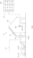
- FIG. 1 is a conceptual view of a power supply system 10 according to a preferred embodiment.
- the power supply system 10 includes a solar light power generation device 20, a plurality of power storage apparatuses 30, a charge/discharge device 40, and a controller 50.
- the power supply system 10 supplies electric power to a home 100.
- the target to which the power supply system 10 supplies power is not limited to the home 100, and may be, for example, an office, a plant, a commercial facility, or the like.
- the power supply system 10 is connected with a commercial system 110 and power loads 120.
- the power loads 120 include an electric vehicle 121 and electric appliances 122 used in the home 100.
- one power storage apparatus 31 is a vehicle-mounted battery 31 mounted on the electric vehicle 121.
- the term "electric vehicle 121" may encompass vehicles, in general, driven by electric power as a source of energy, for example, an electric automobile, a hybrid electric vehicle, a plug-in hybrid electric vehicle and the like.
- the electric vehicle 121 may be a four-wheeled vehicle or a two-wheeled vehicle.
- another power storage apparatus 32, among the plurality of power storage apparatuses 30, is a stationary power storage apparatus 32.
- the power storage apparatus 30 only the vehicle-mounted battery 31 or only the stationary power storage apparatus 32 may be provided.
- the solar light power generation device 20, the stationary power storage apparatus 32 and the charge/discharge device 40 are provided in the home 100.
- the electric vehicle 121 and the vehicle-mounted battery 31 mounted thereon are in the home 100 when the electric vehicle 121 is parked in the home 100, and move to the outside of the home 100 when the electric vehicle 121 is used.
- An operation terminal 50A which is a part of the controller 50, may be in the home 100 or may be carried by a user of the power supply system 10.
- the operation terminal 50A may be a specialized operation terminal or may be a general terminal having an application installed thereon, for example, a smartphone or the like.
- a server 50B, of the controller 50, connected with the operation terminal 50A is provided at a server installation site outside the home 100.
- Functions of the server 50B may be provided by a computer on the cloud.
- a part of, or the entirety of, the functions of the server 50B may be provided by a device provided in the home 100.
- the power storage apparatuses 30 each include a power storage device that, upon receipt of power from the solar light power generation device 20 or the commercial system 110, stores the power thereon and releases the power to the power loads 120.
- the power storage apparatuses 30 each include, for example, a lithium ion secondary battery.
- the power storage device included in each of the power storage apparatuses 30 is not limited to the lithium ion secondary battery.
- the plurality of power storage apparatuses 30 may include the same type of power storage devices or different types of power storage devices.
- the charge/discharge device 40 is connected with the solar light power generation device 20 and the power storage apparatuses 30.
- the charge/discharge device 40 is connectable with the power loads 120.
- the charge/discharge device 40 stores the power generated by the solar light power generation device 20 on the power storage apparatuses 30, and discharges the power stored on the power storage apparatuses 30 to the power loads 120.
- the charge/discharge device 40 is also connected with the commercial system 110.
- the charge/discharge device 40 supplies surplus power, of the power generated by the solar light power generation device 20, to the commercial system 110 by reverse power flow.
- the charge/discharge device 40 supplies the power supplied from the commercial system 110 to the power loads 120, or stores the power supplied from the commercial system 110 on the power storage apparatuses 30.
- the charge/discharge device 40 may be divided into a plurality of devices, for example, a device that converts the power generated by the solar light power generation device 20 into AC power and a device that converts AC power from the commercial system 110 into DC power and stores the DC power on the power storage apparatuses 30.
- the plurality of devices may be installed at different sites.
- the controller 50 controls the charge/discharge device 40 to store the power from the solar light power generation device 20 or the commercial system 110 on the power storage apparatuses 30, to discharge the power from the solar light power generation device 20 or the commercial system 110 to the power loads 120, and to discharge the power stored on the power storage apparatuses 30 to the power loads 120.
- the controller 50 includes a power generation amount estimator 51, a power consumption amount estimator 52, a first setter 53, a first charge/discharge controller 54, a determinator 55, a second setter 56, a second charge/discharge controller 57, and an updater 58.
- the controller 50 has a computer program installed thereon, the computer program being configured to have a computer realize such processors.
- the controller 50 controls the power supply system 10 in accordance with the computer program.
- the computer program may be stored in, for example, a non-transitory computer readable medium.
- Examples of the non-transitory computer readable medium include magnetic recording media (such as flexible disks, magnetic tapes, and hard disk drives) and CD-ROMs.
- the power generation amount estimator 51 estimates the amount of power generation by the solar light power generation device 20.
- the power generation amount estimator 51 acquires weather forecast information, and estimates the amount of power generation by the solar light power generation device 20 based on the acquired weather forecast information.
- the amount of power generation by the solar light power generation device 20 is large when the weather is fine with a large amount of solar radiation, and is small when the weather is cloudy with a small amount of solar radiation or during nighttime.
- the power generation amount estimator 51 estimates the amount of power generation by the solar light power generation device 20 on a time slot-by-time slot basis, based on the weather forecast information on a time slot-by-time slot basis.
- the power consumption amount estimator 52 estimates the amount of power consumption by the power loads 120, the power being supplied from each of the power storage apparatuses 30. Regarding the vehicle-mounted battery 31, the power consumption amount estimator 52 estimates the amount of power consumption by the electric vehicle 121 and the amount of power consumption by other power loads (in this embodiment, the electric appliances 122 in the home 100). In this manner, the power consumption amount estimator 52 estimates the amount of power consumed from the vehicle-mounted battery 31. The power consumption amount estimator 52 estimates the amount of power consumption by the electric vehicle 121 based on data on a past running distance of the electric vehicle 121.
- the power consumption amount estimator 52 estimates the amount of power consumption by the electric vehicle 121 on a weekday based on the average value of the running distances of the electric vehicle 121 on weekdays. For example, in the case where the running distance of the electric vehicle 121 on a day off varies significantly, the power consumption amount estimator 52 assumes that the running distance of the electric vehicle 121 on a day off is a predefined distance that is longer than the average running distance on weekdays. The power consumption amount estimator 52 estimates the amount of power consumption by the electric appliances 122 based on data on past power consumption, estimated temperatures acquired from the weather forecast information, and the like.
- the amount of power consumption by each of the electric vehicle 121 and the electric appliance 122 is estimated on a time slot-by-time slot basis. If there is a situation where, for example, the time to use the electric vehicle 121 is defined, or nobody is in the home 100 and the air-conditioner is not used during the daytime of a weekday, such a situation may be reflected on the estimation of the amount of power consumption. A part of the information reflected on the estimation of the amount of power consumption may be, for example, input to the operation terminal 50A by the user of the power supply system 10.
- the first setter 53 sets a standard power storage amount Vs (see FIG. 2 ), which is smaller than a power storage amount of the power storage apparatus 30 in a fully charged state.
- the standard power storage amount Vs is the upper limit of the power storage amount in a normal state.
- the standard power storage amount Vs represents a ratio (%) with respect to the power storage amount in a fully charged state, that is, so-called SOC (State of Charge).
- SOC State of Charge
- each power storage apparatus 30 is not put into the state close to the fully charged state.
- the standard power storage amount Vs in each of the plurality of power storage apparatuses 30 is preset in accordance with the type, the specifications and the like of the respective power storage apparatus 30.
- the first charge/discharge controller 54 controls the charge/discharge device 40 to store the power generated by the solar light power generation device 20 on each power storage apparatus 30 at a level of the standard power storage amount Vs described above or smaller. In this preferred embodiment, the first charge/discharge controller 54 supplies the power loads 120 with the power generated by the solar light power generation device 20. In the case where there is surplus power in the power generated by the solar light power generation device 20, the first charge/discharge controller 54 controls the charge/discharge device 40 to store the power on each power storage apparatus 30 up to a level of the standard power storage amount Vs.
- the first charge/discharge controller 54 supplies the surplus power to the commercial system 110 by the reverse power flow.
- the first charge/discharge controller 54 controls the charge/discharge device 40 to supply the power stored on the power storage apparatuses 30 to the power loads 120.
- the first charge/discharge controller 54 compensates for the shortfall by the power from the commercial system 110.
- the amount of power to be stored on each of the power storage apparatuses 30 under the control of the first charge/discharge controller 54 may be any amount equal to, or smaller than, the standard power storage amount Vs, and is not limited to the standard power storage amount Vs.
- the first charge/discharge controller 54 may store, on each power storage apparatus 30, the power generated by the solar light power generation device 20 at a level of a power storage amount that is set based on the estimate of the amount of power generation provided by the power generation amount estimator 51 and the estimate of the amount of power consumption provided by the power consumption amount estimator 52 (such a set amount should not exceed the standard power storage amount Vs).
- the determinator 55 determines whether or not the storage of the power on the vehicle-mounted battery 31 up to a level of the standard power storage amount Vs makes the electric vehicle 121 capable of running as expected, based on the amount of power generation estimated by the power generation amount estimator 51 and also the amount of power consumption by the electric vehicle 121 and the amount of power consumption by other power loads (in this embodiment, the electric appliances 122 in the home 100) estimated by the power consumption amount estimator 52.
- the determinator 55 determines that the electric vehicle 121 is not capable of running as expected.
- the second setter 56 sets a temporary power storage amount Vt (see FIG. 4 ), which is larger than the standard power storage amount Vs and at which the electric vehicle 121 is capable of running as expected.
- Vt a temporary power storage amount
- the second setter 56 raises the maximum power storage amount for each of the power storage apparatuses 30 of the day immediately previous to the day of interest, from the standard power storage amount Vs to the temporary power storage amount Vt.
- the second charge/discharge controller 57 controls the charge/discharge device 40 to store the power generated by the solar light power generation device 20 on the vehicle-mounted battery 31 up to a level of the temporary power storage amount Vt.
- the updater 28 updates the standard power storage amount Vs based on a function regarding aging of the power storage apparatuses 30.
- the updater 28 increases the value of the standard power storage amount Vs in accordance with the decrease.
- the function regarding the aging of the power storage apparatuses 30 may be, for example, a function representing the relationship between the total charging time and the decrease in the capacitance.
- the power supply system 10 may be configured to measure an index of each of the power storage apparatuses 30 (e.g., resistance), and the function regarding the aging of the power storage apparatuses 30 may be, for example, a function representing the relationship between such an index (i.e., resistance) and the decrease in the capacitance.
- an index of each of the power storage apparatuses 30 e.g., resistance
- the function regarding the aging of the power storage apparatuses 30 may be, for example, a function representing the relationship between such an index (i.e., resistance) and the decrease in the capacitance.
- FIG. 2 is a graph showing, along time, the power storage amount in the vehicle-mounted battery 31 of the fine day and the day immediately previous thereto.
- the horizontal axis represents the time (24-hour system).
- the vertical axis represents the power storage amount in the vehicle-mounted battery 31.
- the horizontal axis and the vertical axis represent the same.
- the power storage amount in the vehicle-mounted battery 31 is increased gradually and reaches the standard power storage amount Vs (time period T4 in FIG. 2 ).
- Vs standard power storage amount
- a sufficient amount of power to cover the amount of power consumption by the electric appliances 122 and the amount of power consumption by the electric vehicle 121 on the day of interest is stored on the vehicle-mounted battery 31.
- the electric vehicle 121 is capable of running as expected.
- FIG. 3 is a graph showing, along time, the power storage amount in the vehicle-mounted battery 31 in the case where the maximum power storage amount for the vehicle-mounted battery 31 is kept at the standard power storage amount Vs, regardless of the estimate of the amount of power generation and the estimate of the amount of power consumption, although the day of interest is a cloudy day.
- the power storage amount in the vehicle-mounted battery 31 increases and decrease in substantially the same manner as in FIG. 2 .
- the amount of power generation by the solar light power generation device 20 is small, and the power storage amount in the vehicle-mounted battery 31 increases with a low gradient.
- the power storage amount in the vehicle-mounted battery 31 is not allowed to reach a power storage amount Vn, which is necessary to make the electric vehicle 121 capable of running as expected, by the start of time period T5, i.e., the time when the electric vehicle is to be used. Therefore, the electric vehicle 121 is not capable of running as expected. If the power storage amount in the vehicle-mounted battery 31 is to reach the power storage amount Vn by the start of the time period T5, i.e., the time when the electric vehicle 121 is to be used, power needs to be supplied from the commercial system 110.
- FIG. 4 is a graph showing, along time, the power storage amount in the vehicle-mounted battery 31 on a cloudy day and the day immediately previous thereto.
- the maximum power storage amount for the vehicle-mounted battery 31 of the day immediately previous to the cloudy day is raised to the temporary power storage amount Vt.
- the power storage amount in the vehicle-mounted battery 31 during the daytime (time when the power generation is possible) of the day immediately previous to the day of interest is kept at the temporary power storage amount Vt (time period T1 in FIG. 4 ).
- the value of the temporary power storage amount Vt may change in accordance with the estimate of the amount of power generation and the estimate of the amount of power consumption.
- the day of interest is a cloudy day, and therefore, the power storage amount in the vehicle-mounted battery 31 increases slowly.
- the remaining power storage amount Vr in the vehicle-mounted battery 31 at the end of the time period T3 (nighttime) is large, and therefore, the power storage amount in the vehicle-mounted battery 31 is allowed to reach the power storage amount Vn, which is necessary to make the electric vehicle 121 capable of running as expected, by the start of the time period T5, i.e., the time when the electric vehicle is to be used.
- no power needs to be supplied from the commercial system 110 in order to make the electric vehicle 121 capable of running as expected.
- the power storage amount in each power storage apparatus 30 is kept at the level of the standard power storage amount Vs or smaller as long as there is no problem regarding the running of the electric vehicle 121. This suppresses deterioration in each power storage apparatus 30.
- the maximum power storage amount for the vehicle-mounted battery 31 is raised to the temporary power storage amount Vt.
- Vt temporary power storage amount
- the amount of power generation by the solar light power generation device 20 is decreased.
- the situation where the maximum power storage amount for the vehicle-mounted battery 31 needs to be raised to the temporary power storage amount Vt is not limited to such a case.
- the amount of power consumption is estimated to be large for the reasons that, among others, the estimated running distance of the electric vehicle 121 is long or the estimated amount of power consumption by the electric appliances 122 in the home 100 is large.
- the maximum power storage amount for the vehicle-mounted battery 31 is raised to the temporary power storage amount Vt.
- the power supply system 10 further includes the power generation amount estimator 51, the power consumption amount estimator 52, the determinator 55, the second setter 56, and the second charge/discharge controller 57.
- the power generation amount estimator 51 estimates the amount of power generation by the solar light power generation device 20.
- the power consumption amount estimator 52 estimates the amount of power consumption by the electric vehicle 121 based on data on a past running distance of the electric vehicle 121 and estimates the amount of power consumption by other power loads (in this embodiment, the electric appliances 122 in the home 100) other than the electric vehicle 121, and thus estimates the amount of power to be consumed from the vehicle-mounted battery 31.
- the determinator 55 determines whether or not the storage of the power on the vehicle-mounted battery 31 up to a level of the standard power storage amount Vs makes the electric vehicle 121 capable of running as expected, based on the amount of power generation estimated by the power generation amount estimator 51 and the amounts of power consumption by the electric vehicle 121 and the other power loads (the electric appliances 122 in the home 100) estimated by the power consumption amount estimator 52.
- the second setter 56 sets the temporary power storage amount Vt, which is larger than the standard power storage amount Vs and at which the electric vehicle 121 is capable of running as expected.
- the second charge/discharge controller 57 controls the charge/discharge device 40 to store the power generated by the solar light power generation device 20 on the vehicle-mounted battery 31 up to a level of the temporary power storage amount Vt.
- the power supply system 10 further includes the updater 58 updating the standard power storage amount Vs based on a function regarding aging of the power storage apparatuses 30.
- a power management method disclosed herein manages a power supply system including a solar light power generation device, a power storage apparatus, and a charge/discharge device connected with the solar light power generation device and the power storage apparatus and connectable with power loads, the charge/discharge device storing power generated by the solar light power generation device on the power storage apparatus and discharging the power stored on the power storage apparatus to the power loads.
- the power management method includes the following steps: a first setting step of setting a standard power storage amount as an amount of power to be stored on the power storage apparatus, the standard power storage amount being smaller than a power storage amount in a fully charged state; and a standard power storage step of controlling the charge/discharge device to store the power generated by the solar light power generation device on the power storage apparatus at a level of the standard power storage amount or smaller.
- the power storage apparatus may be a vehicle-mounted battery mounted on an electric vehicle, and the power loads may include the electric vehicle.
- the method may further include a power generation amount estimation step of estimating an amount of power generation by the solar light power generation device; a power consumption amount estimation step of estimating an amount of power consumption by the electric vehicle based on data on a past running distance of the electric vehicle and estimating an amount of power consumption by other power loads other than the electric vehicle among the power loads, to estimate an amount of power to be consumed from the vehicle-mounted battery; a determination step of determining whether or not storage of the power on the vehicle-mounted battery up to a level of the standard power storage amount makes the electric vehicle capable of running as expected, based on the estimated amount of power generation and the estimated amounts of power consumption by the electric vehicle and the other power loads; a second setting step of, in the case where the electric vehicle is determined as not being capable of running as expected, setting a temporary power storage amount, which is larger than the standard power storage amount and at which the electric vehicle is capable of running
Landscapes
- Engineering & Computer Science (AREA)
- Power Engineering (AREA)
- Transportation (AREA)
- Mechanical Engineering (AREA)
- Sustainable Energy (AREA)
- Sustainable Development (AREA)
- Life Sciences & Earth Sciences (AREA)
- Business, Economics & Management (AREA)
- Health & Medical Sciences (AREA)
- Economics (AREA)
- Water Supply & Treatment (AREA)
- Primary Health Care (AREA)
- Tourism & Hospitality (AREA)
- Physics & Mathematics (AREA)
- General Business, Economics & Management (AREA)
- General Physics & Mathematics (AREA)
- Theoretical Computer Science (AREA)
- Strategic Management (AREA)
- Marketing (AREA)
- Human Resources & Organizations (AREA)
- General Health & Medical Sciences (AREA)
- Public Health (AREA)
- Charge And Discharge Circuits For Batteries Or The Like (AREA)
- Supply And Distribution Of Alternating Current (AREA)
- Secondary Cells (AREA)
- Electric Propulsion And Braking For Vehicles (AREA)
Abstract
A power supply system (10) includes a solar light power generation device (20); a power storage apparatus (30); a charge/discharge device (40) connected with the solar light power generation device (20) and the power storage apparatus (30) and connectable with power loads (120), the charge/discharge device (40) storing power generated by the solar light power generation device (20) on the power storage apparatus (30) and discharging the power stored on the power storage apparatus (30) to the power loads (120); a first setter (53) setting a standard power storage amount (Vs) as an amount of power to be stored on the power storage apparatus (30), the standard power storage amount (Vs) being smaller than a power storage amount thereof in a fully charged state; and a first charge/discharge controller (54) controlling the charge/discharge device (40) to store the power generated by the solar light power generation device (20) on the power storage apparatus (30) at a level of the standard power storage amount (Vs) or smaller.
Description
- The present invention relates to a power supply system, a non-transitory computer readable medium storing a computer program activating the power supply system, and a power management method.
- For example,
Japanese Laid-Open Patent Publication No. 2009-284586 Japanese Laid-Open Patent Publication No. 2009-284586 Japanese Laid-Open Patent Publication No. 2009-284586 - In the case where the plan to decrease the reverse power flow to the commercial system is to be carried out, the power system described in
Japanese Laid-Open Patent Publication No. 2009-284586 Japanese Laid-Open Patent Publication No. 2009-284586 - With the power system described in
Japanese Laid-Open Patent Publication No. 2009-284586 - A power supply system proposed herein includes a solar light power generation device; a power storage apparatus; a charge/discharge device connected with the solar light power generation device and the power storage apparatus and connectable with power loads, the charge/discharge device storing power generated by the solar light power generation device on the power storage apparatus and discharging the power stored on the power storage apparatus to the power loads; a first setter setting a standard power storage amount as an amount of power to be stored on the power storage apparatus, the standard power storage amount being smaller than a power storage amount thereof in a fully charged state; and a first charge/discharge controller controlling the charge/discharge device to store the power generated by the solar light power generation device on the power storage apparatus at a level of the standard power storage amount or smaller.
- With the above-described power supply system, the first charge/discharge controller stores the power on the power storage apparatus at a level of the standard power storage amount or smaller. Therefore, the power storage apparatus is not left in a state close to the fully charged state. This suppresses deterioration in the power storage apparatus.
- A non-transitory computer readable medium proposed herein stores a computer program configured to have a computer realize a first charge/discharge controller issuing, to a charge/discharge device connected with a solar light power generation device and a power storage apparatus and connectable with power loads, a command to store power generated by the solar light power generation device on the power storage apparatus and a command to discharge the power stored on the power storage apparatus to the power loads; and a first setter setting a standard power storage amount as an amount of power to be stored on the power storage apparatus, the standard power storage amount being smaller than a power storage amount thereof in a fully charged state. The first charge/discharge controller issues, to the charge/discharge device, a command to store the power generated by the solar light power generation device on the power storage apparatus at a level of the standard power storage amount or smaller.
- A power management method proposed herein manages a power supply system including a solar light power generation device, a power storage apparatus, and a charge/discharge device connected with the solar light power generation device and the power storage apparatus and connectable with power loads, the charge/discharge device storing power generated by the solar light power generation device on the power storage apparatus and discharging the power stored on the power storage apparatus to the power loads. The power management method proposed herein includes setting a standard power storage amount as an amount of power to be stored on the power storage apparatus, the standard power storage amount being smaller than a power storage amount thereof in a fully charged state; and storing the power generated by the solar light power generation device on the power storage apparatus, by controlling the charge/discharge device, at a level of the standard power storage amount or smaller.
- The non-transitory computer readable medium storing the computer program and the power management method described above may also provide the same effects as those of the above-described power supply system.
-
-
FIG. 1 is a conceptual view of a power supply system. -
FIG. 2 is a graph showing, along time, the power storage amount in a vehicle-mounted battery on a fine day and the day immediately previous thereto. -
FIG. 3 is a graph showing, along time, the power storage amount in the vehicle-mounted battery in the case where the maximum power storage amount is not raised. -
FIG. 4 is a graph showing, along time, the power storage amount in the vehicle-mounted battery on a cloudy day and the day immediately previous thereto. - Hereinafter, a preferred embodiment of a power supply system disclosed herein will be described with reference to the drawings. The embodiment described herein is not intended to specifically limit the present invention, needless to say. Unless otherwise specified, the present invention is not limited to the embodiment described herein. Elements and parts having the same functions will bear the same reference signs where appropriate, and overlapping descriptions will be omitted where appropriate.
-
FIG. 1 is a conceptual view of apower supply system 10 according to a preferred embodiment. As shown inFIG. 1 , thepower supply system 10 according to this preferred embodiment includes a solar lightpower generation device 20, a plurality ofpower storage apparatuses 30, a charge/discharge device 40, and acontroller 50. In this embodiment, thepower supply system 10 supplies electric power to ahome 100. It should be noted that the target to which thepower supply system 10 supplies power is not limited to thehome 100, and may be, for example, an office, a plant, a commercial facility, or the like. Thepower supply system 10 is connected with acommercial system 110 andpower loads 120. In this embodiment, thepower loads 120 include anelectric vehicle 121 andelectric appliances 122 used in thehome 100. - Among the plurality of
power storage apparatuses 30, onepower storage apparatus 31 is a vehicle-mountedbattery 31 mounted on theelectric vehicle 121. The term "electric vehicle 121" may encompass vehicles, in general, driven by electric power as a source of energy, for example, an electric automobile, a hybrid electric vehicle, a plug-in hybrid electric vehicle and the like. Theelectric vehicle 121 may be a four-wheeled vehicle or a two-wheeled vehicle. In this embodiment, anotherpower storage apparatus 32, among the plurality ofpower storage apparatuses 30, is a stationarypower storage apparatus 32. There is no specific limitation on the number of the vehicle-mountedbattery 31 or on the number of the stationarypower storage apparatus 32. As thepower storage apparatus 30, only the vehicle-mountedbattery 31 or only the stationarypower storage apparatus 32 may be provided. There may be only onepower storage apparatus 30, instead of the plurality ofpower storage apparatuses 30. - In this embodiment, the solar light
power generation device 20, the stationarypower storage apparatus 32 and the charge/discharge device 40 are provided in thehome 100. Theelectric vehicle 121 and the vehicle-mountedbattery 31 mounted thereon are in thehome 100 when theelectric vehicle 121 is parked in thehome 100, and move to the outside of thehome 100 when theelectric vehicle 121 is used. Anoperation terminal 50A, which is a part of thecontroller 50, may be in thehome 100 or may be carried by a user of thepower supply system 10. Theoperation terminal 50A may be a specialized operation terminal or may be a general terminal having an application installed thereon, for example, a smartphone or the like. In this embodiment, aserver 50B, of thecontroller 50, connected with theoperation terminal 50A is provided at a server installation site outside thehome 100. Functions of theserver 50B may be provided by a computer on the cloud. A part of, or the entirety of, the functions of theserver 50B may be provided by a device provided in thehome 100. There is no specific limitation on the site where thecontroller 50 is installed or on the manner of installation of thecontroller 50. - The
power storage apparatuses 30 each include a power storage device that, upon receipt of power from the solar lightpower generation device 20 or thecommercial system 110, stores the power thereon and releases the power to thepower loads 120. Thepower storage apparatuses 30 each include, for example, a lithium ion secondary battery. The power storage device included in each of thepower storage apparatuses 30 is not limited to the lithium ion secondary battery. The plurality ofpower storage apparatuses 30 may include the same type of power storage devices or different types of power storage devices. - The charge/
discharge device 40 is connected with the solar lightpower generation device 20 and thepower storage apparatuses 30. The charge/discharge device 40 is connectable with thepower loads 120. The charge/discharge device 40 stores the power generated by the solar lightpower generation device 20 on thepower storage apparatuses 30, and discharges the power stored on thepower storage apparatuses 30 to thepower loads 120. The charge/discharge device 40 is also connected with thecommercial system 110. The charge/discharge device 40 supplies surplus power, of the power generated by the solar lightpower generation device 20, to thecommercial system 110 by reverse power flow. In the case where the power generated by the solar lightpower generation device 20 is insufficient, the charge/discharge device 40 supplies the power supplied from thecommercial system 110 to thepower loads 120, or stores the power supplied from thecommercial system 110 on thepower storage apparatuses 30. The charge/discharge device 40 may be divided into a plurality of devices, for example, a device that converts the power generated by the solar lightpower generation device 20 into AC power and a device that converts AC power from thecommercial system 110 into DC power and stores the DC power on thepower storage apparatuses 30. The plurality of devices may be installed at different sites. - The
controller 50 controls the charge/discharge device 40 to store the power from the solar lightpower generation device 20 or thecommercial system 110 on thepower storage apparatuses 30, to discharge the power from the solar lightpower generation device 20 or thecommercial system 110 to thepower loads 120, and to discharge the power stored on thepower storage apparatuses 30 to thepower loads 120. As shown inFIG. 1 , thecontroller 50 includes a powergeneration amount estimator 51, a powerconsumption amount estimator 52, afirst setter 53, a first charge/discharge controller 54, adeterminator 55, a second setter 56, a second charge/discharge controller 57, and anupdater 58. Thecontroller 50 has a computer program installed thereon, the computer program being configured to have a computer realize such processors. Thecontroller 50 controls thepower supply system 10 in accordance with the computer program. The computer program may be stored in, for example, a non-transitory computer readable medium. Examples of the non-transitory computer readable medium include magnetic recording media (such as flexible disks, magnetic tapes, and hard disk drives) and CD-ROMs. - The power
generation amount estimator 51 estimates the amount of power generation by the solar lightpower generation device 20. In more detail, the powergeneration amount estimator 51 acquires weather forecast information, and estimates the amount of power generation by the solar lightpower generation device 20 based on the acquired weather forecast information. The amount of power generation by the solar lightpower generation device 20 is large when the weather is fine with a large amount of solar radiation, and is small when the weather is cloudy with a small amount of solar radiation or during nighttime. In this embodiment, the powergeneration amount estimator 51 estimates the amount of power generation by the solar lightpower generation device 20 on a time slot-by-time slot basis, based on the weather forecast information on a time slot-by-time slot basis. - The power
consumption amount estimator 52 estimates the amount of power consumption by the power loads 120, the power being supplied from each of thepower storage apparatuses 30. Regarding the vehicle-mountedbattery 31, the powerconsumption amount estimator 52 estimates the amount of power consumption by theelectric vehicle 121 and the amount of power consumption by other power loads (in this embodiment, theelectric appliances 122 in the home 100). In this manner, the powerconsumption amount estimator 52 estimates the amount of power consumed from the vehicle-mountedbattery 31. The powerconsumption amount estimator 52 estimates the amount of power consumption by theelectric vehicle 121 based on data on a past running distance of theelectric vehicle 121. For example, the powerconsumption amount estimator 52 estimates the amount of power consumption by theelectric vehicle 121 on a weekday based on the average value of the running distances of theelectric vehicle 121 on weekdays. For example, in the case where the running distance of theelectric vehicle 121 on a day off varies significantly, the powerconsumption amount estimator 52 assumes that the running distance of theelectric vehicle 121 on a day off is a predefined distance that is longer than the average running distance on weekdays. The powerconsumption amount estimator 52 estimates the amount of power consumption by theelectric appliances 122 based on data on past power consumption, estimated temperatures acquired from the weather forecast information, and the like. - The amount of power consumption by each of the
electric vehicle 121 and theelectric appliance 122 is estimated on a time slot-by-time slot basis. If there is a situation where, for example, the time to use theelectric vehicle 121 is defined, or nobody is in thehome 100 and the air-conditioner is not used during the daytime of a weekday, such a situation may be reflected on the estimation of the amount of power consumption. A part of the information reflected on the estimation of the amount of power consumption may be, for example, input to theoperation terminal 50A by the user of thepower supply system 10. - Regarding the amount of power to be stored on each of the
power storage apparatuses 30, thefirst setter 53 sets a standard power storage amount Vs (seeFIG. 2 ), which is smaller than a power storage amount of thepower storage apparatus 30 in a fully charged state. The standard power storage amount Vs is the upper limit of the power storage amount in a normal state. In this embodiment, the standard power storage amount Vs represents a ratio (%) with respect to the power storage amount in a fully charged state, that is, so-called SOC (State of Charge). The power storage device of eachpower storage apparatus 30 is deteriorated progressively by a fully charged state or a state close to the fully charged state (hereinafter, also referred to simply as the "state close to the fully charged state") being continued. From the point of view of life of eachpower storage apparatus 30, it is desired that eachpower storage apparatus 30 is not put into the state close to the fully charged state. In this preferred embodiment, the standard power storage amount Vs in each of the plurality ofpower storage apparatuses 30 is preset in accordance with the type, the specifications and the like of the respectivepower storage apparatus 30. - The first charge/
discharge controller 54 controls the charge/discharge device 40 to store the power generated by the solar lightpower generation device 20 on eachpower storage apparatus 30 at a level of the standard power storage amount Vs described above or smaller. In this preferred embodiment, the first charge/discharge controller 54 supplies the power loads 120 with the power generated by the solar lightpower generation device 20. In the case where there is surplus power in the power generated by the solar lightpower generation device 20, the first charge/discharge controller 54 controls the charge/discharge device 40 to store the power on eachpower storage apparatus 30 up to a level of the standard power storage amount Vs. When the power storage amounts in both of thepower storage apparatuses 30 reach the standard power storage amount Vs, the first charge/discharge controller 54 supplies the surplus power to thecommercial system 110 by the reverse power flow. In a situation where the amount of power generation by the solar lightpower generation device 20 is smaller than the amount of power consumption by the power loads 120, for example, during nighttime, the first charge/discharge controller 54 controls the charge/discharge device 40 to supply the power stored on thepower storage apparatuses 30 to the power loads 120. In the case where it is expected that the power generation merely by the solar lightpower generation device 20 does not allow an amount of power, sufficient to cover the amount of power consumption by the power loads 120, to be stored on thepower storage apparatuses 30, the first charge/discharge controller 54 compensates for the shortfall by the power from thecommercial system 110. - The amount of power to be stored on each of the
power storage apparatuses 30 under the control of the first charge/discharge controller 54 may be any amount equal to, or smaller than, the standard power storage amount Vs, and is not limited to the standard power storage amount Vs. For example, the first charge/discharge controller 54 may store, on eachpower storage apparatus 30, the power generated by the solar lightpower generation device 20 at a level of a power storage amount that is set based on the estimate of the amount of power generation provided by the powergeneration amount estimator 51 and the estimate of the amount of power consumption provided by the power consumption amount estimator 52 (such a set amount should not exceed the standard power storage amount Vs). - The
determinator 55 determines whether or not the storage of the power on the vehicle-mountedbattery 31 up to a level of the standard power storage amount Vs makes theelectric vehicle 121 capable of running as expected, based on the amount of power generation estimated by the powergeneration amount estimator 51 and also the amount of power consumption by theelectric vehicle 121 and the amount of power consumption by other power loads (in this embodiment, theelectric appliances 122 in the home 100) estimated by the powerconsumption amount estimator 52. For example, there may be a case where even if the standard power storage amount Vs is stored on the vehicle-mountedbattery 31 by the day immediately previous to the day of interest, the estimated amount of power generation of the day of interest is small or the estimated amount of power consumption of the day of interest is large, and as a result, it is estimated that a sufficient amount of power to make theelectric vehicle 121 capable of running as expected will not be left in the vehicle-mountedbattery 31 at the time when theelectric vehicle 121 is to be used. In this case, thedeterminator 55 determines that theelectric vehicle 121 is not capable of running as expected. - In the case where the
determinator 55 determines that theelectric vehicle 121 is not capable of running as expected, the second setter 56 sets a temporary power storage amount Vt (seeFIG. 4 ), which is larger than the standard power storage amount Vs and at which theelectric vehicle 121 is capable of running as expected. As a result, an inconvenience may be avoided where theelectric vehicle 121 is not capable of running as expected due to the insufficiency in the amount of power with which the vehicle-mountedbattery 31 is charged. In this case, the second setter 56 raises the maximum power storage amount for each of thepower storage apparatuses 30 of the day immediately previous to the day of interest, from the standard power storage amount Vs to the temporary power storage amount Vt. As a result, even if the amount of power generation of the day of interest is estimated to be small, or the amount of power consumption of the day of interest is estimated to be large, a sufficient amount of power to make theelectric vehicle 121 capable of running as expected will be left in the vehicle-mountedbattery 31 at the time when theelectric vehicle 121 is to be used. In addition, such a change in the setting decreases the number of cases where the shortfall in the power needs to be compensated for by the power from thecommercial system 110 on the day of interest. - The second charge/
discharge controller 57 controls the charge/discharge device 40 to store the power generated by the solar lightpower generation device 20 on the vehicle-mountedbattery 31 up to a level of the temporary power storage amount Vt. - The updater 28 updates the standard power storage amount Vs based on a function regarding aging of the
power storage apparatuses 30. When the capacitance of eachpower storage apparatus 30 is decreased by aging, the updater 28 increases the value of the standard power storage amount Vs in accordance with the decrease. As a result, even in a state where thepower storage apparatuses 30 are deteriorated to some extent, thepower supply system 10 is usable in substantially the same manner as before the deterioration. There is no specific limitation on the function regarding the aging of thepower storage apparatuses 30. The function regarding the aging of thepower storage apparatuses 30 may be, for example, a function representing the relationship between the total charging time and the decrease in the capacitance. Thepower supply system 10 may be configured to measure an index of each of the power storage apparatuses 30 (e.g., resistance), and the function regarding the aging of thepower storage apparatuses 30 may be, for example, a function representing the relationship between such an index (i.e., resistance) and the decrease in the capacitance. - Hereinafter, an example of operation of the
power supply system 10 will be described. The examples of operation are for a day on which the amount of power generation by the solar lightpower generation device 20 is estimated to be large (hereinafter, referred to also as a "fine day") and the day immediately previous thereto, and for a day on which the amount of power generation by the solar lightpower generation device 20 is estimated to be small (hereinafter, referred to also as a "cloudy day") and the day immediate previous thereto. -
FIG. 2 is a graph showing, along time, the power storage amount in the vehicle-mountedbattery 31 of the fine day and the day immediately previous thereto. InFIG. 2 , the horizontal axis represents the time (24-hour system). InFIG. 2 , the vertical axis represents the power storage amount in the vehicle-mountedbattery 31. In each ofFIG. 3 andFIG. 4 , the horizontal axis and the vertical axis represent the same. - In the case where the day of interest is estimated to be a fine day, the estimated amount of power generation by the solar light
power generation device 20 is large. In this case, as shown inFIG. 2 , the power storage amount in the vehicle-mountedbattery 31 during the daytime (time when the power generation is possible) of the day immediately previous to the day of interest is kept at the standard power storage amount Vs (time period T1 inFIG. 2 ). Assuming that, for example, theelectric vehicle 121 is used in the evening every day, the vehicle-mountedbattery 31 is not charged during that time and the power stored on the vehicle-mountedbattery 31 is consumed by the electric vehicle 121 (time period T2 inFIG. 2 ). In time period T3 inFIG. 2 (nighttime), the power stored on the vehicle-mountedbattery 31 is consumed by theelectric appliances 122 in thehome 100. As a result, the power storage amount in the vehicle-mountedbattery 31 is decreased. - When the power generation by the solar light
power generation device 20 is started on the morning of the day of interest, the power storage amount in the vehicle-mountedbattery 31 is increased gradually and reaches the standard power storage amount Vs (time period T4 inFIG. 2 ). As a result, a sufficient amount of power to cover the amount of power consumption by theelectric appliances 122 and the amount of power consumption by theelectric vehicle 121 on the day of interest is stored on the vehicle-mountedbattery 31. In time period T5 inFIG. 2 , theelectric vehicle 121 is capable of running as expected. -
FIG. 3 is a graph showing, along time, the power storage amount in the vehicle-mountedbattery 31 in the case where the maximum power storage amount for the vehicle-mountedbattery 31 is kept at the standard power storage amount Vs, regardless of the estimate of the amount of power generation and the estimate of the amount of power consumption, although the day of interest is a cloudy day. Until the morning of the day of interest (until the end of the time period T3), the power storage amount in the vehicle-mountedbattery 31 increases and decrease in substantially the same manner as inFIG. 2 . As shown inFIG. 3 , on such a cloudy day, the amount of power generation by the solar lightpower generation device 20 is small, and the power storage amount in the vehicle-mountedbattery 31 increases with a low gradient. Therefore, the power storage amount in the vehicle-mountedbattery 31 is not allowed to reach a power storage amount Vn, which is necessary to make theelectric vehicle 121 capable of running as expected, by the start of time period T5, i.e., the time when the electric vehicle is to be used. Therefore, theelectric vehicle 121 is not capable of running as expected. If the power storage amount in the vehicle-mountedbattery 31 is to reach the power storage amount Vn by the start of the time period T5, i.e., the time when theelectric vehicle 121 is to be used, power needs to be supplied from thecommercial system 110. -
FIG. 4 is a graph showing, along time, the power storage amount in the vehicle-mountedbattery 31 on a cloudy day and the day immediately previous thereto. As shown inFIG. 4 , in this preferred embodiment, given the information that the day of interest is a cloudy day, the maximum power storage amount for the vehicle-mountedbattery 31 of the day immediately previous to the cloudy day is raised to the temporary power storage amount Vt. As a result, the power storage amount in the vehicle-mountedbattery 31 during the daytime (time when the power generation is possible) of the day immediately previous to the day of interest is kept at the temporary power storage amount Vt (time period T1 inFIG. 4 ). The value of the temporary power storage amount Vt may change in accordance with the estimate of the amount of power generation and the estimate of the amount of power consumption. The maximum power storage amount for the vehicle-mountedbattery 31 of the day immediately previous to the day of interest is raised to the temporary power storage amount Vt, so that as shown inFIG. 4 , a remaining power storage amount Vr in the vehicle-mountedbattery 31 at the end of the time period T3 (nighttime) is larger than inFIG. 2 andFIG. 3 . - The day of interest is a cloudy day, and therefore, the power storage amount in the vehicle-mounted
battery 31 increases slowly. However, the remaining power storage amount Vr in the vehicle-mountedbattery 31 at the end of the time period T3 (nighttime) is large, and therefore, the power storage amount in the vehicle-mountedbattery 31 is allowed to reach the power storage amount Vn, which is necessary to make theelectric vehicle 121 capable of running as expected, by the start of the time period T5, i.e., the time when the electric vehicle is to be used. This makes theelectric vehicle 121 capable of running as expected. In this example, no power needs to be supplied from thecommercial system 110 in order to make theelectric vehicle 121 capable of running as expected. - As described above, with the
power supply system 10 in this preferred embodiment, the power storage amount in eachpower storage apparatus 30 is kept at the level of the standard power storage amount Vs or smaller as long as there is no problem regarding the running of theelectric vehicle 121. This suppresses deterioration in eachpower storage apparatus 30. In the case where it is estimated that there is a problem regarding the running of theelectric vehicle 121, the maximum power storage amount for the vehicle-mountedbattery 31 is raised to the temporary power storage amount Vt. As a result, it is at least estimated that theelectric vehicle 121 is capable of running as expected. In many cases among the cases where it is estimated that theelectric vehicle 121 is capable of running as expected, theelectric vehicle 121 actually runs as expected. The number of cases where the power from thecommercial system 110 needs to be allotted in order to make theelectric vehicle 121 capable of running as expected is decreased. - In the above-described example, it is assumed that the amount of power generation by the solar light
power generation device 20 is decreased. The situation where the maximum power storage amount for the vehicle-mountedbattery 31 needs to be raised to the temporary power storage amount Vt is not limited to such a case. For example, there may be case where the amount of power consumption is estimated to be large for the reasons that, among others, the estimated running distance of theelectric vehicle 121 is long or the estimated amount of power consumption by theelectric appliances 122 in thehome 100 is large. In such a case also, the maximum power storage amount for the vehicle-mountedbattery 31 is raised to the temporary power storage amount Vt. - Hereinafter, functions and effects provided by the
power supply system 10 according to this preferred embodiment will be described. - The
power supply system 10 according to this preferred embodiment includes the solar lightpower generation device 20, thepower storage apparatuses 30, and the charge/discharge device 40 connected with the solar lightpower generation device 20 and thepower storage apparatuses 30. The charge/discharge device 40 is connectable with the power loads 120, and stores the power generated by the solar lightpower generation device 20 on thepower storage apparatuses 30 and discharges the power stored on thepower storage apparatuses 30 to the power loads 120. Thepower supply system 10 further includes thefirst setter 53 setting the standard power storage amount Vs, which is smaller than the power storage amount in the fully charged state, as an amount of power to be stored on thepower storage apparatuses 30, and the first charge/discharge controller 54 controlling the charge/discharge device 40 to store the power generated by the solar lightpower generation device 20 on each of thepower storage apparatuses 30 at a level of the standard power storage amount Vs or smaller. With thepower supply system 10 having such a configuration, the first charge/discharge controller 54 stores the power on each of thepower storage apparatuses 30 at a level of the standard power storage amount Vs or smaller. Therefore, thepower storage apparatuses 30 are not left in a state close to the fully charged state. This suppresses deterioration in thepower storage apparatuses 30. - In this preferred embodiment, at least one of the
power storage apparatuses 30 is the vehicle-mountedbattery 31 mounted on theelectric vehicle 121. The power loads 120 include theelectric vehicle 121. With such a configuration, the vehicle-mountedbattery 31 on theelectric vehicle 121 is utilized, so that the capacitance of the stationarypower storage device 32 may be decreased. - The
power supply system 10 according to this preferred embodiment further includes the powergeneration amount estimator 51, the powerconsumption amount estimator 52, thedeterminator 55, the second setter 56, and the second charge/discharge controller 57. The powergeneration amount estimator 51 estimates the amount of power generation by the solar lightpower generation device 20. The powerconsumption amount estimator 52 estimates the amount of power consumption by theelectric vehicle 121 based on data on a past running distance of theelectric vehicle 121 and estimates the amount of power consumption by other power loads (in this embodiment, theelectric appliances 122 in the home 100) other than theelectric vehicle 121, and thus estimates the amount of power to be consumed from the vehicle-mountedbattery 31. Thedeterminator 55 determines whether or not the storage of the power on the vehicle-mountedbattery 31 up to a level of the standard power storage amount Vs makes theelectric vehicle 121 capable of running as expected, based on the amount of power generation estimated by the powergeneration amount estimator 51 and the amounts of power consumption by theelectric vehicle 121 and the other power loads (theelectric appliances 122 in the home 100) estimated by the powerconsumption amount estimator 52. In the case where thedeterminator 55 determines that theelectric vehicle 121 is not capable of running as expected, the second setter 56 sets the temporary power storage amount Vt, which is larger than the standard power storage amount Vs and at which theelectric vehicle 121 is capable of running as expected. The second charge/discharge controller 57 controls the charge/discharge device 40 to store the power generated by the solar lightpower generation device 20 on the vehicle-mountedbattery 31 up to a level of the temporary power storage amount Vt. - With such a configuration, the maximum power storage amount for the vehicle-mounted
battery 31 is raised to the temporary power storage amount Vt, so that theelectric vehicle 121 is made capable of running as expected. In addition, the number of cases where the power from thecommercial system 110 needs to be allotted in order to make theelectric vehicle 121 capable of running as expected may be decreased. - The
power supply system 10 according to this preferred embodiment further includes theupdater 58 updating the standard power storage amount Vs based on a function regarding aging of thepower storage apparatuses 30. With such a configuration, even in a state where thepower storage apparatuses 30 are deteriorated to some extent, thepower supply system 10 is usable in substantially the same manner as before the deterioration. - A preferred embodiment of the
power supply system 10 proposed herein is described above. The above-described preferred embodiment is merely one example, and the present invention may be carried out in other embodiments. For example, in the above-described preferred embodiment, the amount of power generation by the solar lightpower generation device 20 or the amount of power consumption by the power loads 120 are estimated by thepower supply system 10. Alternatively, the amount of power generation by the solar lightpower generation device 20 or the amount of power consumption by the power loads 120 may be estimated by another system or a human. A part of the computation or the control performed by thepower supply system 10 in the above-described preferred embodiment may be performed by another system or a human. - A power management method disclosed herein manages a power supply system including a solar light power generation device, a power storage apparatus, and a charge/discharge device connected with the solar light power generation device and the power storage apparatus and connectable with power loads, the charge/discharge device storing power generated by the solar light power generation device on the power storage apparatus and discharging the power stored on the power storage apparatus to the power loads. The power management method includes the following steps: a first setting step of setting a standard power storage amount as an amount of power to be stored on the power storage apparatus, the standard power storage amount being smaller than a power storage amount in a fully charged state; and a standard power storage step of controlling the charge/discharge device to store the power generated by the solar light power generation device on the power storage apparatus at a level of the standard power storage amount or smaller. There is no specific limitation on the subject performing the above-described steps.
- In the power management method disclosed herein, the power storage apparatus may be a vehicle-mounted battery mounted on an electric vehicle, and the power loads may include the electric vehicle. The method may further include a power generation amount estimation step of estimating an amount of power generation by the solar light power generation device; a power consumption amount estimation step of estimating an amount of power consumption by the electric vehicle based on data on a past running distance of the electric vehicle and estimating an amount of power consumption by other power loads other than the electric vehicle among the power loads, to estimate an amount of power to be consumed from the vehicle-mounted battery; a determination step of determining whether or not storage of the power on the vehicle-mounted battery up to a level of the standard power storage amount makes the electric vehicle capable of running as expected, based on the estimated amount of power generation and the estimated amounts of power consumption by the electric vehicle and the other power loads; a second setting step of, in the case where the electric vehicle is determined as not being capable of running as expected, setting a temporary power storage amount, which is larger than the standard power storage amount and at which the electric vehicle is capable of running as expected; and a temporary power storage step of storing the power generated by the solar light power generation device on the vehicle-mounted battery up to a level of the temporary power storage amount.
- The method may further include an updating step of updating the standard power storage amount based on a function regarding aging of the power storage apparatus.
- The above-described embodiments do not limit the present invention in any way unless otherwise specified. The technology disclosed herein may be altered in any of various manners. The elements and the processes referred to herein may each be omitted where appropriate, or may be combined in an appropriate manner, unless any specific problem is caused.
- This specification includes the following disclosure.
- Item 1: A power supply system, comprising:
- a solar light power generation device;
- a power storage apparatus;
- a charge/discharge device connected with the solar light power generation device and the power storage apparatus and connectable with power loads, the charge/discharge device storing power generated by the solar light power generation device on the power storage apparatus and discharging the power stored on the power storage apparatus to the power loads;
- a first setter setting a standard power storage amount as an amount of power to be stored on the power storage apparatus, the standard power storage amount being smaller than a power storage amount thereof in a fully charged state; and
- a first charge/discharge controller controlling the charge/discharge device to store the power generated by the solar light power generation device on the power storage apparatus at a level of the standard power storage amount or smaller.
- Item 2: The power supply system according to item 1, wherein:
- the power storage apparatus is a vehicle-mounted battery mounted on an electric vehicle, and
- the power loads include the electric vehicle.
- Item 3: The power supply system according to item 2, further comprising:
- a power generation amount estimator estimating an amount of power generation by the solar light power generation device,
- a power consumption amount estimator estimating an amount of power consumption by the electric vehicle based on data on a past running distance of the electric vehicle and estimating an amount of power consumption by other power loads other than the electric vehicle among the power loads, to estimate an amount of power to be consumed from the vehicle-mounted battery,
- a determinator determining whether or not storage of the power on the vehicle-mounted battery up to a level of the standard power storage amount makes the electric vehicle capable of running as expected, based on the amount of power generation estimated by the power generation amount estimator and the amounts of power consumption by the electric vehicle and the other power loads estimated by the power consumption amount estimator,
- a second setter, in the case where the determinator determines that the electric vehicle is not capable of running as expected, setting a temporary power storage amount, which is larger than the standard power storage amount and at which the electric vehicle is capable of running as expected, and
- a second charge/discharge controller controlling the charge/discharge device to store the power generated by the solar light power generation device on the vehicle-mounted battery up to a level of the temporary power storage amount.
- Item 4: The power supply system according to any one of items 1 through 3, further comprising an updater updating the standard power storage amount based on a function regarding aging of the power storage apparatus.
- Item 5: A non-transitory computer readable medium storing a computer program configured to have a computer realize:
- a first charge/discharge controller issuing, to a charge/discharge device connected with a solar light power generation device and a power storage apparatus and connectable with power loads, a command to store power generated by the solar light power generation device on the power storage apparatus and a command to discharge the power stored on the power storage apparatus to the power loads; and
- a first setter setting a standard power storage amount as an amount of power to be stored on the power storage apparatus, the standard power storage amount being smaller than a power storage amount thereof in a fully charged state,
- wherein the first charge/discharge controller issues, to the charge/discharge device, a command to store the power generated by the solar light power generation device on the power storage apparatus at a level of the standard power storage amount or smaller.
- Item 6:
The non-transitory computer readable medium according to Item 5, wherein the computer program is configured to have the computer realize, in the case where the power storage apparatus is a vehicle-mounted battery mounted on an electric vehicle and the power loads include the electric vehicle:- a power generation amount estimator estimating an amount of power generation by the solar light power generation device,
- a power consumption amount estimator estimating an amount of power consumption by the electric vehicle based on data on a past running distance of the electric vehicle and estimating an amount of power consumption by other power loads other than the electric vehicle among the power loads, to estimate an amount of power to be consumed from the vehicle-mounted battery,
- a determinator determining whether or not storage of the power on the vehicle-mounted battery up to a level of the standard power storage amount makes the electric vehicle capable of running as expected, based on the amount of power generation estimated by the power generation amount estimator and the amounts of power consumption by the electric vehicle and the other power loads estimated by the power consumption amount estimator,
- a second setter, in the case where the determinator determines that the electric vehicle is not capable of running as expected, setting a temporary power storage amount, which is larger than the standard power storage amount and at which the electric vehicle is capable of running as expected, and
- a second charge/discharge controller issuing, to the charge/discharge device, a command to store the power generated by the solar light power generation device on the vehicle-mounted battery up to a level of the temporary power storage amount.
- Item 7: The non-transitory computer readable medium according to
Item 5 or 6, wherein the computer program is configured to have the computer realize an updater updating the standard power storage amount based on a function regarding aging of the power storage apparatus. - Item 8: A power management method for managing a power supply system, the power supply system including:
- a solar light power generation device,
- a power storage apparatus, and
- a charge/discharge device connected with the solar light power generation device and the power storage apparatus and connectable with power loads, the charge/discharge device storing power generated by the solar light power generation device on the power storage apparatus and discharging the power stored on the power storage apparatus to the power loads,
- the power management method comprising:
- setting a standard power storage amount as an amount of power to be stored on the power storage apparatus, the standard power storage amount being smaller than a power storage amount thereof in a fully charged state; and
- storing the power generated by the solar light power generation device on the power storage apparatus, by controlling the charge/discharge device, at a level of the standard power storage amount or smaller.
- Item 9:
The power management method according to item 8, wherein:- the power storage apparatus is a vehicle-mounted battery mounted on an electric vehicle,
- the power loads include the electric vehicle, and
- the power management method further includes:
- estimating an amount of power generation by the solar light power generation device,
- estimating an amount of power to be consumed from the vehicle-mounted battery by estimating an amount of power consumption by the electric vehicle based on data on a past running distance of the electric vehicle and by estimating an amount of power consumption by other power loads other than the electric vehicle among the power loads,
- determining whether or not storage of the power on the vehicle-mounted battery up to a level of the standard power storage amount makes the electric vehicle capable of running as expected, based on the estimated amount of power generation and the estimated amounts of power consumption by the electric vehicle and the other power loads,
- setting a temporary power storage amount, in the case where the electric vehicle is determined as not being capable of running as expected, which is larger than the standard power storage amount and at which the electric vehicle is capable of running as expected, and
- storing the power generated by the solar light power generation device on the vehicle-mounted battery up to a level of the temporary power storage amount.
- Item 10: The power management method according to item 8 or 9, further comprising updating the standard power storage amount based on a function regarding aging of the power storage apparatus.
Claims (10)
- A power supply system (10), comprising:a solar light power generation device (20);a power storage apparatus (30);a charge/discharge device (40) connected with the solar light power generation device (20) and the power storage apparatus (30) and connectable with power loads (120), the charge/discharge device (40) storing power generated by the solar light power generation device (20) on the power storage apparatus (30) and discharging the power stored on the power storage apparatus (30) to the power loads (120);a first setter (53) setting a standard power storage amount (Vs) as an amount of power to be stored on the power storage apparatus (30), the standard power storage amount (Vs) being smaller than a power storage amount thereof in a fully charged state; anda first charge/discharge controller (54) controlling the charge/discharge device (40) to store the power generated by the solar light power generation device (20) on the power storage apparatus (30) at a level of the standard power storage amount (Vs) or smaller.
- The power supply system (10) according to claim 1, wherein:the power storage apparatus (30) is a vehicle-mounted battery (31) mounted on an electric vehicle (121), andthe power loads (120) include the electric vehicle (121).
- The power supply system (10) according to claim 2, further comprising:a power generation amount estimator (51) estimating an amount of power generation by the solar light power generation device (20),a power consumption amount estimator (52) estimating an amount of power consumption by the electric vehicle (121) based on data on a past running distance of the electric vehicle (121) and estimating an amount of power consumption by other power loads (122) other than the electric vehicle (121) among the power loads (120), to estimate an amount of power to be consumed from the vehicle-mounted battery (31),a determinator (55) determining whether or not storage of the power on the vehicle-mounted battery (31) up to a level of the standard power storage amount (Vs) makes the electric vehicle (121) capable of running as expected, based on the amount of power generation estimated by the power generation amount estimator (51) and the amounts of power consumption by the electric vehicle (121) and the other power loads (122) estimated by the power consumption amount estimator (52),a second setter (56), in the case where the determinator (55) determines that the electric vehicle (121) is not capable of running as expected, setting a temporary power storage amount (Vt), which is larger than the standard power storage amount (Vs) and at which the electric vehicle (121) is capable of running as expected, anda second charge/discharge controller (57) controlling the charge/discharge device (40) to store the power generated by the solar light power generation device (20) on the vehicle-mounted battery (31) up to a level of the temporary power storage amount (Vt).
- The power supply system (10) according to any one of claims 1 through 3, further comprising an updater (58) updating the standard power storage amount (Vs) based on a function regarding aging of the power storage apparatus (30).
- A non-transitory computer readable medium storing a computer program configured to have a computer realize:a first charge/discharge controller (54) issuing, to a charge/discharge device (40) connected with a solar light power generation device (20) and a power storage apparatus (30) and connectable with power loads (120), a command to store power generated by the solar light power generation device (20) on the power storage apparatus (30) and a command to discharge the power stored on the power storage apparatus (30) to the power loads (120); anda first setter (53) setting a standard power storage amount (Vs) as an amount of power to be stored on the power storage apparatus (30), the standard power storage amount (Vs) being smaller than a power storage amount thereof in a fully charged state,wherein the first charge/discharge controller (54) issues, to the charge/discharge device (40), a command to store the power generated by the solar light power generation device (20) on the power storage apparatus (30) at a level of the standard power storage amount (Vs) or smaller.
- The non-transitory computer readable medium according to claim 5, wherein the computer program is configured to have the computer realize, in the case where the power storage apparatus (30) is a vehicle-mounted battery (31) mounted on an electric vehicle (121) and the power loads (120) include the electric vehicle (121):a power generation amount estimator (51) estimating an amount of power generation by the solar light power generation device (20),a power consumption amount estimator (52) estimating an amount of power consumption by the electric vehicle (121) based on data on a past running distance of the electric vehicle (121) and estimating an amount of power consumption by other power loads (122) other than the electric vehicle (121) among the power loads (120), to estimate an amount of power to be consumed from the vehicle-mounted battery (31),a determinator (55) determining whether or not storage of the power on the vehicle-mounted battery (31) up to a level of the standard power storage amount (Vs) makes the electric vehicle (121) capable of running as expected, based on the amount of power generation estimated by the power generation amount estimator (51) and the amounts of power consumption by the electric vehicle (121) and the other power loads (122) estimated by the power consumption amount estimator (52),a second setter (56), in the case where the determinator (55) determines that the electric vehicle (121) is not capable of running as expected, setting a temporary power storage amount (Vt), which is larger than the standard power storage amount (Vs) and at which the electric vehicle (121) is capable of running as expected, anda second charge/discharge controller (57) issuing, to the charge/discharge device (40), a command to store the power generated by the solar light power generation device (20) on the vehicle-mounted battery (31) up to a level of the temporary power storage amount (Vt).
- The non-transitory computer readable medium according to claim 5 or 6, wherein the computer program is configured to have the computer realize an updater (58) updating the standard power storage amount (Vs) based on a function regarding aging of the power storage apparatus (30).
- A power management method for managing a power supply system (10), the power supply system (10) including:a solar light power generation device (20),a power storage apparatus (30), anda charge/discharge device (40) connected with the solar light power generation device (20) and the power storage apparatus (30) and connectable with power loads (120), the charge/discharge device (40) storing power generated by the solar light power generation device (20) on the power storage apparatus (30) and discharging the power stored on the power storage apparatus (30) to the power loads (120),the power management method comprising:setting a standard power storage amount (Vs) as an amount of power to be stored on the power storage apparatus (30), the standard power storage amount (Vs) being smaller than a power storage amount thereof in a fully charged state; andstoring the power generated by the solar light power generation device (20) on the power storage apparatus (30), by controlling the charge/discharge device (40), at a level of the standard power storage amount (Vs) or smaller.
- The power management method according to claim 8, wherein:the power storage apparatus (30) is a vehicle-mounted battery (31) mounted on an electric vehicle (121),the power loads (120) include the electric vehicle (121), andthe power management method further includes:estimating an amount of power generation by the solar light power generation device (20),estimating an amount of power to be consumed from the vehicle-mounted battery (31) by estimating an amount of power consumption by the electric vehicle (121) based on data on a past running distance of the electric vehicle (121) and by estimating an amount of power consumption by other power loads (122) other than the electric vehicle (121) among the power loads (120),determining whether or not storage of the power on the vehicle-mounted battery (31) up to a level of the standard power storage amount (Vs) makes the electric vehicle (121) capable of running as expected, based on the estimated amount of power generation and the estimated amounts of power consumption by the electric vehicle (121) and the other power loads (122),setting a temporary power storage amount (Vt), in the case where the electric vehicle (121) is determined as not being capable of running as expected, which is larger than the standard power storage amount (Vs) and at which the electric vehicle (121) is capable of running as expected, andstoring the power generated by the solar light power generation device (20) on the vehicle-mounted battery (31) up to a level of the temporary power storage amount (Vt).
- The power management method according to claim 8 or 9, further comprising updating the standard power storage amount (Vs) based on a function regarding aging of the power storage apparatus (30).
Applications Claiming Priority (1)
| Application Number | Priority Date | Filing Date | Title |
|---|---|---|---|
| JP2023100444A JP7774599B2 (en) | 2023-06-20 | 2023-06-20 | Power supply system, computer program, and power management method |
Publications (1)
| Publication Number | Publication Date |
|---|---|
| EP4480742A1 true EP4480742A1 (en) | 2024-12-25 |
Family
ID=91249003
Family Applications (1)
| Application Number | Title | Priority Date | Filing Date |
|---|---|---|---|
| EP24177622.8A Pending EP4480742A1 (en) | 2023-06-20 | 2024-05-23 | Power supply system, non-transitory computer readable medium, and power management method |
Country Status (5)
| Country | Link |
|---|---|
| US (1) | US12587016B2 (en) |
| EP (1) | EP4480742A1 (en) |
| JP (1) | JP7774599B2 (en) |
| KR (1) | KR20240178220A (en) |
| CN (1) | CN119171602A (en) |
Citations (5)
| Publication number | Priority date | Publication date | Assignee | Title |
|---|---|---|---|---|
| JP2009284586A (en) | 2008-05-20 | 2009-12-03 | Nippon Telegr & Teleph Corp <Ntt> | Power system and its control method |
| SE1100491A1 (en) * | 2010-07-07 | 2011-09-12 | Volvo Lastvagnar Ab | Method for adapted battery charging / discharging |
| US11305667B2 (en) * | 2017-11-24 | 2022-04-19 | Toyota Jidosha Kabushiki Kaisha | Vehicle and power control system |
| US20230150387A1 (en) * | 2021-11-15 | 2023-05-18 | Toyota Jidosha Kabushiki Kaisha | Power system, vehicle, and information processor |
| EP4009480B1 (en) * | 2020-12-03 | 2023-05-24 | Commissariat à l'Energie Atomique et aux Energies Alternatives | Method for managing a state of charge of an accumulator to ensure optimized ageing |
Family Cites Families (8)
| Publication number | Priority date | Publication date | Assignee | Title |
|---|---|---|---|---|
| JPH1051968A (en) | 1996-08-05 | 1998-02-20 | Nissan Motor Co Ltd | Method for charging battery |
| JP3754254B2 (en) * | 1999-11-26 | 2006-03-08 | 三洋電機株式会社 | Battery charge / discharge control method |
| JP2011151891A (en) | 2010-01-19 | 2011-08-04 | Sony Corp | Method and apparatus for charging secondary battery |
| JP2011160514A (en) * | 2010-01-29 | 2011-08-18 | Pioneer Electronic Corp | Charge control apparatus, charge control method, program and recording medium |
| JP5510259B2 (en) * | 2010-10-07 | 2014-06-04 | 株式会社デンソー | Vehicle power control device |
| US20140132214A1 (en) | 2011-06-17 | 2014-05-15 | Toyota Jidosha Kabushiki Kaisha | Electrically powered vehicle and method for controlling electrically powered vehicle |
| JP6053554B2 (en) * | 2013-02-18 | 2016-12-27 | 三菱重工業株式会社 | Power management apparatus, charge / discharge planning apparatus, charge / discharge planning method, and program |
| JP7072539B2 (en) * | 2019-04-11 | 2022-05-20 | 本田技研工業株式会社 | Setting device, setting method, program and control device |
-
2023
- 2023-06-20 JP JP2023100444A patent/JP7774599B2/en active Active
-
2024
- 2024-05-23 EP EP24177622.8A patent/EP4480742A1/en active Pending
- 2024-06-13 US US18/742,535 patent/US12587016B2/en active Active
- 2024-06-17 KR KR1020240078130A patent/KR20240178220A/en active Pending
- 2024-06-19 CN CN202410788715.1A patent/CN119171602A/en active Pending
Patent Citations (5)
| Publication number | Priority date | Publication date | Assignee | Title |
|---|---|---|---|---|
| JP2009284586A (en) | 2008-05-20 | 2009-12-03 | Nippon Telegr & Teleph Corp <Ntt> | Power system and its control method |
| SE1100491A1 (en) * | 2010-07-07 | 2011-09-12 | Volvo Lastvagnar Ab | Method for adapted battery charging / discharging |
| US11305667B2 (en) * | 2017-11-24 | 2022-04-19 | Toyota Jidosha Kabushiki Kaisha | Vehicle and power control system |
| EP4009480B1 (en) * | 2020-12-03 | 2023-05-24 | Commissariat à l'Energie Atomique et aux Energies Alternatives | Method for managing a state of charge of an accumulator to ensure optimized ageing |
| US20230150387A1 (en) * | 2021-11-15 | 2023-05-18 | Toyota Jidosha Kabushiki Kaisha | Power system, vehicle, and information processor |
Also Published As
| Publication number | Publication date |
|---|---|
| US20240429714A1 (en) | 2024-12-26 |
| JP2025001077A (en) | 2025-01-08 |
| US12587016B2 (en) | 2026-03-24 |
| KR20240178220A (en) | 2024-12-30 |
| CN119171602A (en) | 2024-12-20 |
| JP7774599B2 (en) | 2025-11-21 |
Similar Documents
| Publication | Publication Date | Title |
|---|---|---|
| US8525475B2 (en) | Management system for exchange electric storage devices and management method for exchange electric storage devices | |
| US10442302B2 (en) | Battery charging control methods, electrical vehicle charging methods, battery charging control apparatus, and electrical vehicles | |
| US20130134940A1 (en) | Power control apparatus | |
| US20220080844A1 (en) | Electric vehicle charging to reduce utility cost | |
| JP6285848B2 (en) | Control between vehicle and power system | |
| JP5490834B2 (en) | Charge / feed device, charge / feed management device, energy management system, and charge / feed management method | |
| WO2015041171A1 (en) | Charging management device, charging management system and charging management method | |
| EP4251464B1 (en) | Method and system for adaptively charging of electric vehicles | |
| JP6832254B2 (en) | Charge control server, charge control system and program | |
| WO2013128635A1 (en) | Storage battery analysis system, storage battery analysis method, and storage battery analysis program | |
| CN118651117B (en) | Dynamic regulation system and method for electric automobile participation power grid based on V2G technology | |
| CN102612784A (en) | Determination and usage of reserve energy in stored energy systems | |
| KR102304092B1 (en) | Power management system for electronic vehicles and the battery room's temperature control method using the system | |
| CN113352842A (en) | Vehicle-mounted air conditioner, control method thereof and computer-readable storage medium | |
| EP4480742A1 (en) | Power supply system, non-transitory computer readable medium, and power management method | |
| WO2024141536A1 (en) | Prediction-based battery swapping charging control with pre-charge battery levels | |
| EP4552911A1 (en) | Electrical energy supply system, non-transient computer-readable medium, and charging method for electric vehicles | |
| CN109347123B (en) | A charge and discharge control method based on vehicle three-terminal controller | |
| US20250115149A1 (en) | Control device | |
| US20250026227A1 (en) | Systems and Methods for Optimizing Charging Schedules of Electric Vehicles with Varying Electricity Price and Charging Curves | |
| CN121246632A (en) | Intelligent control method and system for unmanned equipment battery | |
| JP2024049071A (en) | Mobile store control method and mobile store control device | |
| CN119611139A (en) | Method and device for determining charging strategy of charging station, electronic equipment and medium |
Legal Events
| Date | Code | Title | Description |
|---|---|---|---|
| PUAI | Public reference made under article 153(3) epc to a published international application that has entered the european phase |
Free format text: ORIGINAL CODE: 0009012 |
|
| STAA | Information on the status of an ep patent application or granted ep patent |
Free format text: STATUS: REQUEST FOR EXAMINATION WAS MADE |
|
| 17P | Request for examination filed |
Effective date: 20240523 |
|
| AK | Designated contracting states |
Kind code of ref document: A1 Designated state(s): AL AT BE BG CH CY CZ DE DK EE ES FI FR GB GR HR HU IE IS IT LI LT LU LV MC ME MK MT NL NO PL PT RO RS SE SI SK SM TR |