JP6285848B2 - Control between vehicle and power system - Google Patents
Control between vehicle and power system Download PDFInfo
- Publication number
- JP6285848B2 JP6285848B2 JP2014232067A JP2014232067A JP6285848B2 JP 6285848 B2 JP6285848 B2 JP 6285848B2 JP 2014232067 A JP2014232067 A JP 2014232067A JP 2014232067 A JP2014232067 A JP 2014232067A JP 6285848 B2 JP6285848 B2 JP 6285848B2
- Authority
- JP
- Japan
- Prior art keywords
- soc
- charging
- electric vehicle
- time
- charge
- Prior art date
- Legal status (The legal status is an assumption and is not a legal conclusion. Google has not performed a legal analysis and makes no representation as to the accuracy of the status listed.)
- Expired - Fee Related
Links
- 238000000034 method Methods 0.000 claims description 88
- 238000007599 discharging Methods 0.000 claims description 6
- 238000001514 detection method Methods 0.000 description 23
- 238000004146 energy storage Methods 0.000 description 15
- 238000004891 communication Methods 0.000 description 12
- 238000010295 mobile communication Methods 0.000 description 8
- 238000010248 power generation Methods 0.000 description 8
- 230000008859 change Effects 0.000 description 6
- 230000008569 process Effects 0.000 description 5
- 230000005540 biological transmission Effects 0.000 description 4
- 230000003287 optical effect Effects 0.000 description 4
- 238000005265 energy consumption Methods 0.000 description 3
- 230000008901 benefit Effects 0.000 description 2
- 238000004590 computer program Methods 0.000 description 2
- 230000001934 delay Effects 0.000 description 2
- 230000005611 electricity Effects 0.000 description 2
- 230000006870 function Effects 0.000 description 2
- 238000012544 monitoring process Methods 0.000 description 2
- 230000006399 behavior Effects 0.000 description 1
- 238000002485 combustion reaction Methods 0.000 description 1
- 230000008878 coupling Effects 0.000 description 1
- 238000010168 coupling process Methods 0.000 description 1
- 238000005859 coupling reaction Methods 0.000 description 1
- 230000003111 delayed effect Effects 0.000 description 1
- 238000010586 diagram Methods 0.000 description 1
- 230000000977 initiatory effect Effects 0.000 description 1
- 239000004973 liquid crystal related substance Substances 0.000 description 1
- 238000012423 maintenance Methods 0.000 description 1
- 238000005259 measurement Methods 0.000 description 1
- 238000012986 modification Methods 0.000 description 1
- 230000004048 modification Effects 0.000 description 1
- 238000012545 processing Methods 0.000 description 1
- 230000001172 regenerating effect Effects 0.000 description 1
- 230000003068 static effect Effects 0.000 description 1
- 239000002699 waste material Substances 0.000 description 1
Images


Classifications
-
- B—PERFORMING OPERATIONS; TRANSPORTING
- B60—VEHICLES IN GENERAL
- B60L—PROPULSION OF ELECTRICALLY-PROPELLED VEHICLES; SUPPLYING ELECTRIC POWER FOR AUXILIARY EQUIPMENT OF ELECTRICALLY-PROPELLED VEHICLES; ELECTRODYNAMIC BRAKE SYSTEMS FOR VEHICLES IN GENERAL; MAGNETIC SUSPENSION OR LEVITATION FOR VEHICLES; MONITORING OPERATING VARIABLES OF ELECTRICALLY-PROPELLED VEHICLES; ELECTRIC SAFETY DEVICES FOR ELECTRICALLY-PROPELLED VEHICLES
- B60L58/00—Methods or circuit arrangements for monitoring or controlling batteries or fuel cells, specially adapted for electric vehicles
- B60L58/10—Methods or circuit arrangements for monitoring or controlling batteries or fuel cells, specially adapted for electric vehicles for monitoring or controlling batteries
- B60L58/12—Methods or circuit arrangements for monitoring or controlling batteries or fuel cells, specially adapted for electric vehicles for monitoring or controlling batteries responding to state of charge [SoC]
- B60L58/13—Maintaining the SoC within a determined range
-
- B—PERFORMING OPERATIONS; TRANSPORTING
- B60—VEHICLES IN GENERAL
- B60L—PROPULSION OF ELECTRICALLY-PROPELLED VEHICLES; SUPPLYING ELECTRIC POWER FOR AUXILIARY EQUIPMENT OF ELECTRICALLY-PROPELLED VEHICLES; ELECTRODYNAMIC BRAKE SYSTEMS FOR VEHICLES IN GENERAL; MAGNETIC SUSPENSION OR LEVITATION FOR VEHICLES; MONITORING OPERATING VARIABLES OF ELECTRICALLY-PROPELLED VEHICLES; ELECTRIC SAFETY DEVICES FOR ELECTRICALLY-PROPELLED VEHICLES
- B60L53/00—Methods of charging batteries, specially adapted for electric vehicles; Charging stations or on-board charging equipment therefor; Exchange of energy storage elements in electric vehicles
- B60L53/60—Monitoring or controlling charging stations
- B60L53/63—Monitoring or controlling charging stations in response to network capacity
-
- B—PERFORMING OPERATIONS; TRANSPORTING
- B60—VEHICLES IN GENERAL
- B60L—PROPULSION OF ELECTRICALLY-PROPELLED VEHICLES; SUPPLYING ELECTRIC POWER FOR AUXILIARY EQUIPMENT OF ELECTRICALLY-PROPELLED VEHICLES; ELECTRODYNAMIC BRAKE SYSTEMS FOR VEHICLES IN GENERAL; MAGNETIC SUSPENSION OR LEVITATION FOR VEHICLES; MONITORING OPERATING VARIABLES OF ELECTRICALLY-PROPELLED VEHICLES; ELECTRIC SAFETY DEVICES FOR ELECTRICALLY-PROPELLED VEHICLES
- B60L53/00—Methods of charging batteries, specially adapted for electric vehicles; Charging stations or on-board charging equipment therefor; Exchange of energy storage elements in electric vehicles
- B60L53/60—Monitoring or controlling charging stations
- B60L53/64—Optimising energy costs, e.g. responding to electricity rates
-
- B—PERFORMING OPERATIONS; TRANSPORTING
- B60—VEHICLES IN GENERAL
- B60L—PROPULSION OF ELECTRICALLY-PROPELLED VEHICLES; SUPPLYING ELECTRIC POWER FOR AUXILIARY EQUIPMENT OF ELECTRICALLY-PROPELLED VEHICLES; ELECTRODYNAMIC BRAKE SYSTEMS FOR VEHICLES IN GENERAL; MAGNETIC SUSPENSION OR LEVITATION FOR VEHICLES; MONITORING OPERATING VARIABLES OF ELECTRICALLY-PROPELLED VEHICLES; ELECTRIC SAFETY DEVICES FOR ELECTRICALLY-PROPELLED VEHICLES
- B60L53/00—Methods of charging batteries, specially adapted for electric vehicles; Charging stations or on-board charging equipment therefor; Exchange of energy storage elements in electric vehicles
- B60L53/60—Monitoring or controlling charging stations
- B60L53/65—Monitoring or controlling charging stations involving identification of vehicles or their battery types
-
- B—PERFORMING OPERATIONS; TRANSPORTING
- B60—VEHICLES IN GENERAL
- B60L—PROPULSION OF ELECTRICALLY-PROPELLED VEHICLES; SUPPLYING ELECTRIC POWER FOR AUXILIARY EQUIPMENT OF ELECTRICALLY-PROPELLED VEHICLES; ELECTRODYNAMIC BRAKE SYSTEMS FOR VEHICLES IN GENERAL; MAGNETIC SUSPENSION OR LEVITATION FOR VEHICLES; MONITORING OPERATING VARIABLES OF ELECTRICALLY-PROPELLED VEHICLES; ELECTRIC SAFETY DEVICES FOR ELECTRICALLY-PROPELLED VEHICLES
- B60L53/00—Methods of charging batteries, specially adapted for electric vehicles; Charging stations or on-board charging equipment therefor; Exchange of energy storage elements in electric vehicles
- B60L53/60—Monitoring or controlling charging stations
- B60L53/66—Data transfer between charging stations and vehicles
- B60L53/665—Methods related to measuring, billing or payment
-
- B—PERFORMING OPERATIONS; TRANSPORTING
- B60—VEHICLES IN GENERAL
- B60L—PROPULSION OF ELECTRICALLY-PROPELLED VEHICLES; SUPPLYING ELECTRIC POWER FOR AUXILIARY EQUIPMENT OF ELECTRICALLY-PROPELLED VEHICLES; ELECTRODYNAMIC BRAKE SYSTEMS FOR VEHICLES IN GENERAL; MAGNETIC SUSPENSION OR LEVITATION FOR VEHICLES; MONITORING OPERATING VARIABLES OF ELECTRICALLY-PROPELLED VEHICLES; ELECTRIC SAFETY DEVICES FOR ELECTRICALLY-PROPELLED VEHICLES
- B60L55/00—Arrangements for supplying energy stored within a vehicle to a power network, i.e. vehicle-to-grid [V2G] arrangements
-
- H—ELECTRICITY
- H02—GENERATION; CONVERSION OR DISTRIBUTION OF ELECTRIC POWER
- H02J—CIRCUIT ARRANGEMENTS OR SYSTEMS FOR SUPPLYING OR DISTRIBUTING ELECTRIC POWER; SYSTEMS FOR STORING ELECTRIC ENERGY
- H02J3/00—Circuit arrangements for ac mains or ac distribution networks
- H02J3/28—Arrangements for balancing of the load in a network by storage of energy
- H02J3/32—Arrangements for balancing of the load in a network by storage of energy using batteries with converting means
- H02J3/322—Arrangements for balancing of the load in a network by storage of energy using batteries with converting means the battery being on-board an electric or hybrid vehicle, e.g. vehicle to grid arrangements [V2G], power aggregation, use of the battery for network load balancing, coordinated or cooperative battery charging
-
- H—ELECTRICITY
- H02—GENERATION; CONVERSION OR DISTRIBUTION OF ELECTRIC POWER
- H02J—CIRCUIT ARRANGEMENTS OR SYSTEMS FOR SUPPLYING OR DISTRIBUTING ELECTRIC POWER; SYSTEMS FOR STORING ELECTRIC ENERGY
- H02J7/00—Circuit arrangements for charging or depolarising batteries or for supplying loads from batteries
- H02J7/0047—Circuit arrangements for charging or depolarising batteries or for supplying loads from batteries with monitoring or indicating devices or circuits
- H02J7/0048—Detection of remaining charge capacity or state of charge [SOC]
-
- B—PERFORMING OPERATIONS; TRANSPORTING
- B60—VEHICLES IN GENERAL
- B60L—PROPULSION OF ELECTRICALLY-PROPELLED VEHICLES; SUPPLYING ELECTRIC POWER FOR AUXILIARY EQUIPMENT OF ELECTRICALLY-PROPELLED VEHICLES; ELECTRODYNAMIC BRAKE SYSTEMS FOR VEHICLES IN GENERAL; MAGNETIC SUSPENSION OR LEVITATION FOR VEHICLES; MONITORING OPERATING VARIABLES OF ELECTRICALLY-PROPELLED VEHICLES; ELECTRIC SAFETY DEVICES FOR ELECTRICALLY-PROPELLED VEHICLES
- B60L2240/00—Control parameters of input or output; Target parameters
- B60L2240/60—Navigation input
- B60L2240/62—Vehicle position
- B60L2240/622—Vehicle position by satellite navigation
-
- H—ELECTRICITY
- H02—GENERATION; CONVERSION OR DISTRIBUTION OF ELECTRIC POWER
- H02J—CIRCUIT ARRANGEMENTS OR SYSTEMS FOR SUPPLYING OR DISTRIBUTING ELECTRIC POWER; SYSTEMS FOR STORING ELECTRIC ENERGY
- H02J2310/00—The network for supplying or distributing electric power characterised by its spatial reach or by the load
- H02J2310/50—The network for supplying or distributing electric power characterised by its spatial reach or by the load for selectively controlling the operation of the loads
- H02J2310/56—The network for supplying or distributing electric power characterised by its spatial reach or by the load for selectively controlling the operation of the loads characterised by the condition upon which the selective controlling is based
- H02J2310/58—The condition being electrical
-
- H—ELECTRICITY
- H02—GENERATION; CONVERSION OR DISTRIBUTION OF ELECTRIC POWER
- H02J—CIRCUIT ARRANGEMENTS OR SYSTEMS FOR SUPPLYING OR DISTRIBUTING ELECTRIC POWER; SYSTEMS FOR STORING ELECTRIC ENERGY
- H02J3/00—Circuit arrangements for ac mains or ac distribution networks
- H02J3/12—Circuit arrangements for ac mains or ac distribution networks for adjusting voltage in ac networks by changing a characteristic of the network load
- H02J3/14—Circuit arrangements for ac mains or ac distribution networks for adjusting voltage in ac networks by changing a characteristic of the network load by switching loads on to, or off from, network, e.g. progressively balanced loading
-
- Y—GENERAL TAGGING OF NEW TECHNOLOGICAL DEVELOPMENTS; GENERAL TAGGING OF CROSS-SECTIONAL TECHNOLOGIES SPANNING OVER SEVERAL SECTIONS OF THE IPC; TECHNICAL SUBJECTS COVERED BY FORMER USPC CROSS-REFERENCE ART COLLECTIONS [XRACs] AND DIGESTS
- Y02—TECHNOLOGIES OR APPLICATIONS FOR MITIGATION OR ADAPTATION AGAINST CLIMATE CHANGE
- Y02B—CLIMATE CHANGE MITIGATION TECHNOLOGIES RELATED TO BUILDINGS, e.g. HOUSING, HOUSE APPLIANCES OR RELATED END-USER APPLICATIONS
- Y02B70/00—Technologies for an efficient end-user side electric power management and consumption
- Y02B70/30—Systems integrating technologies related to power network operation and communication or information technologies for improving the carbon footprint of the management of residential or tertiary loads, i.e. smart grids as climate change mitigation technology in the buildings sector, including also the last stages of power distribution and the control, monitoring or operating management systems at local level
- Y02B70/3225—Demand response systems, e.g. load shedding, peak shaving
-
- Y—GENERAL TAGGING OF NEW TECHNOLOGICAL DEVELOPMENTS; GENERAL TAGGING OF CROSS-SECTIONAL TECHNOLOGIES SPANNING OVER SEVERAL SECTIONS OF THE IPC; TECHNICAL SUBJECTS COVERED BY FORMER USPC CROSS-REFERENCE ART COLLECTIONS [XRACs] AND DIGESTS
- Y02—TECHNOLOGIES OR APPLICATIONS FOR MITIGATION OR ADAPTATION AGAINST CLIMATE CHANGE
- Y02E—REDUCTION OF GREENHOUSE GAS [GHG] EMISSIONS, RELATED TO ENERGY GENERATION, TRANSMISSION OR DISTRIBUTION
- Y02E60/00—Enabling technologies; Technologies with a potential or indirect contribution to GHG emissions mitigation
-
- Y—GENERAL TAGGING OF NEW TECHNOLOGICAL DEVELOPMENTS; GENERAL TAGGING OF CROSS-SECTIONAL TECHNOLOGIES SPANNING OVER SEVERAL SECTIONS OF THE IPC; TECHNICAL SUBJECTS COVERED BY FORMER USPC CROSS-REFERENCE ART COLLECTIONS [XRACs] AND DIGESTS
- Y02—TECHNOLOGIES OR APPLICATIONS FOR MITIGATION OR ADAPTATION AGAINST CLIMATE CHANGE
- Y02T—CLIMATE CHANGE MITIGATION TECHNOLOGIES RELATED TO TRANSPORTATION
- Y02T10/00—Road transport of goods or passengers
- Y02T10/60—Other road transportation technologies with climate change mitigation effect
- Y02T10/70—Energy storage systems for electromobility, e.g. batteries
-
- Y—GENERAL TAGGING OF NEW TECHNOLOGICAL DEVELOPMENTS; GENERAL TAGGING OF CROSS-SECTIONAL TECHNOLOGIES SPANNING OVER SEVERAL SECTIONS OF THE IPC; TECHNICAL SUBJECTS COVERED BY FORMER USPC CROSS-REFERENCE ART COLLECTIONS [XRACs] AND DIGESTS
- Y02—TECHNOLOGIES OR APPLICATIONS FOR MITIGATION OR ADAPTATION AGAINST CLIMATE CHANGE
- Y02T—CLIMATE CHANGE MITIGATION TECHNOLOGIES RELATED TO TRANSPORTATION
- Y02T10/00—Road transport of goods or passengers
- Y02T10/60—Other road transportation technologies with climate change mitigation effect
- Y02T10/7072—Electromobility specific charging systems or methods for batteries, ultracapacitors, supercapacitors or double-layer capacitors
-
- Y—GENERAL TAGGING OF NEW TECHNOLOGICAL DEVELOPMENTS; GENERAL TAGGING OF CROSS-SECTIONAL TECHNOLOGIES SPANNING OVER SEVERAL SECTIONS OF THE IPC; TECHNICAL SUBJECTS COVERED BY FORMER USPC CROSS-REFERENCE ART COLLECTIONS [XRACs] AND DIGESTS
- Y02—TECHNOLOGIES OR APPLICATIONS FOR MITIGATION OR ADAPTATION AGAINST CLIMATE CHANGE
- Y02T—CLIMATE CHANGE MITIGATION TECHNOLOGIES RELATED TO TRANSPORTATION
- Y02T10/00—Road transport of goods or passengers
- Y02T10/60—Other road transportation technologies with climate change mitigation effect
- Y02T10/72—Electric energy management in electromobility
-
- Y—GENERAL TAGGING OF NEW TECHNOLOGICAL DEVELOPMENTS; GENERAL TAGGING OF CROSS-SECTIONAL TECHNOLOGIES SPANNING OVER SEVERAL SECTIONS OF THE IPC; TECHNICAL SUBJECTS COVERED BY FORMER USPC CROSS-REFERENCE ART COLLECTIONS [XRACs] AND DIGESTS
- Y02—TECHNOLOGIES OR APPLICATIONS FOR MITIGATION OR ADAPTATION AGAINST CLIMATE CHANGE
- Y02T—CLIMATE CHANGE MITIGATION TECHNOLOGIES RELATED TO TRANSPORTATION
- Y02T10/00—Road transport of goods or passengers
- Y02T10/80—Technologies aiming to reduce greenhouse gasses emissions common to all road transportation technologies
- Y02T10/92—Energy efficient charging or discharging systems for batteries, ultracapacitors, supercapacitors or double-layer capacitors specially adapted for vehicles
-
- Y—GENERAL TAGGING OF NEW TECHNOLOGICAL DEVELOPMENTS; GENERAL TAGGING OF CROSS-SECTIONAL TECHNOLOGIES SPANNING OVER SEVERAL SECTIONS OF THE IPC; TECHNICAL SUBJECTS COVERED BY FORMER USPC CROSS-REFERENCE ART COLLECTIONS [XRACs] AND DIGESTS
- Y02—TECHNOLOGIES OR APPLICATIONS FOR MITIGATION OR ADAPTATION AGAINST CLIMATE CHANGE
- Y02T—CLIMATE CHANGE MITIGATION TECHNOLOGIES RELATED TO TRANSPORTATION
- Y02T90/00—Enabling technologies or technologies with a potential or indirect contribution to GHG emissions mitigation
- Y02T90/10—Technologies relating to charging of electric vehicles
- Y02T90/12—Electric charging stations
-
- Y—GENERAL TAGGING OF NEW TECHNOLOGICAL DEVELOPMENTS; GENERAL TAGGING OF CROSS-SECTIONAL TECHNOLOGIES SPANNING OVER SEVERAL SECTIONS OF THE IPC; TECHNICAL SUBJECTS COVERED BY FORMER USPC CROSS-REFERENCE ART COLLECTIONS [XRACs] AND DIGESTS
- Y02—TECHNOLOGIES OR APPLICATIONS FOR MITIGATION OR ADAPTATION AGAINST CLIMATE CHANGE
- Y02T—CLIMATE CHANGE MITIGATION TECHNOLOGIES RELATED TO TRANSPORTATION
- Y02T90/00—Enabling technologies or technologies with a potential or indirect contribution to GHG emissions mitigation
- Y02T90/10—Technologies relating to charging of electric vehicles
- Y02T90/14—Plug-in electric vehicles
-
- Y—GENERAL TAGGING OF NEW TECHNOLOGICAL DEVELOPMENTS; GENERAL TAGGING OF CROSS-SECTIONAL TECHNOLOGIES SPANNING OVER SEVERAL SECTIONS OF THE IPC; TECHNICAL SUBJECTS COVERED BY FORMER USPC CROSS-REFERENCE ART COLLECTIONS [XRACs] AND DIGESTS
- Y02—TECHNOLOGIES OR APPLICATIONS FOR MITIGATION OR ADAPTATION AGAINST CLIMATE CHANGE
- Y02T—CLIMATE CHANGE MITIGATION TECHNOLOGIES RELATED TO TRANSPORTATION
- Y02T90/00—Enabling technologies or technologies with a potential or indirect contribution to GHG emissions mitigation
- Y02T90/10—Technologies relating to charging of electric vehicles
- Y02T90/16—Information or communication technologies improving the operation of electric vehicles
- Y02T90/167—Systems integrating technologies related to power network operation and communication or information technologies for supporting the interoperability of electric or hybrid vehicles, i.e. smartgrids as interface for battery charging of electric vehicles [EV] or hybrid vehicles [HEV]
-
- Y—GENERAL TAGGING OF NEW TECHNOLOGICAL DEVELOPMENTS; GENERAL TAGGING OF CROSS-SECTIONAL TECHNOLOGIES SPANNING OVER SEVERAL SECTIONS OF THE IPC; TECHNICAL SUBJECTS COVERED BY FORMER USPC CROSS-REFERENCE ART COLLECTIONS [XRACs] AND DIGESTS
- Y04—INFORMATION OR COMMUNICATION TECHNOLOGIES HAVING AN IMPACT ON OTHER TECHNOLOGY AREAS
- Y04S—SYSTEMS INTEGRATING TECHNOLOGIES RELATED TO POWER NETWORK OPERATION, COMMUNICATION OR INFORMATION TECHNOLOGIES FOR IMPROVING THE ELECTRICAL POWER GENERATION, TRANSMISSION, DISTRIBUTION, MANAGEMENT OR USAGE, i.e. SMART GRIDS
- Y04S10/00—Systems supporting electrical power generation, transmission or distribution
- Y04S10/12—Monitoring or controlling equipment for energy generation units, e.g. distributed energy generation [DER] or load-side generation
- Y04S10/126—Monitoring or controlling equipment for energy generation units, e.g. distributed energy generation [DER] or load-side generation the energy generation units being or involving electric vehicles [EV] or hybrid vehicles [HEV], i.e. power aggregation of EV or HEV, vehicle to grid arrangements [V2G]
-
- Y—GENERAL TAGGING OF NEW TECHNOLOGICAL DEVELOPMENTS; GENERAL TAGGING OF CROSS-SECTIONAL TECHNOLOGIES SPANNING OVER SEVERAL SECTIONS OF THE IPC; TECHNICAL SUBJECTS COVERED BY FORMER USPC CROSS-REFERENCE ART COLLECTIONS [XRACs] AND DIGESTS
- Y04—INFORMATION OR COMMUNICATION TECHNOLOGIES HAVING AN IMPACT ON OTHER TECHNOLOGY AREAS
- Y04S—SYSTEMS INTEGRATING TECHNOLOGIES RELATED TO POWER NETWORK OPERATION, COMMUNICATION OR INFORMATION TECHNOLOGIES FOR IMPROVING THE ELECTRICAL POWER GENERATION, TRANSMISSION, DISTRIBUTION, MANAGEMENT OR USAGE, i.e. SMART GRIDS
- Y04S20/00—Management or operation of end-user stationary applications or the last stages of power distribution; Controlling, monitoring or operating thereof
- Y04S20/20—End-user application control systems
- Y04S20/222—Demand response systems, e.g. load shedding, peak shaving
-
- Y—GENERAL TAGGING OF NEW TECHNOLOGICAL DEVELOPMENTS; GENERAL TAGGING OF CROSS-SECTIONAL TECHNOLOGIES SPANNING OVER SEVERAL SECTIONS OF THE IPC; TECHNICAL SUBJECTS COVERED BY FORMER USPC CROSS-REFERENCE ART COLLECTIONS [XRACs] AND DIGESTS
- Y04—INFORMATION OR COMMUNICATION TECHNOLOGIES HAVING AN IMPACT ON OTHER TECHNOLOGY AREAS
- Y04S—SYSTEMS INTEGRATING TECHNOLOGIES RELATED TO POWER NETWORK OPERATION, COMMUNICATION OR INFORMATION TECHNOLOGIES FOR IMPROVING THE ELECTRICAL POWER GENERATION, TRANSMISSION, DISTRIBUTION, MANAGEMENT OR USAGE, i.e. SMART GRIDS
- Y04S30/00—Systems supporting specific end-user applications in the sector of transportation
- Y04S30/10—Systems supporting the interoperability of electric or hybrid vehicles
- Y04S30/12—Remote or cooperative charging
-
- Y—GENERAL TAGGING OF NEW TECHNOLOGICAL DEVELOPMENTS; GENERAL TAGGING OF CROSS-SECTIONAL TECHNOLOGIES SPANNING OVER SEVERAL SECTIONS OF THE IPC; TECHNICAL SUBJECTS COVERED BY FORMER USPC CROSS-REFERENCE ART COLLECTIONS [XRACs] AND DIGESTS
- Y04—INFORMATION OR COMMUNICATION TECHNOLOGIES HAVING AN IMPACT ON OTHER TECHNOLOGY AREAS
- Y04S—SYSTEMS INTEGRATING TECHNOLOGIES RELATED TO POWER NETWORK OPERATION, COMMUNICATION OR INFORMATION TECHNOLOGIES FOR IMPROVING THE ELECTRICAL POWER GENERATION, TRANSMISSION, DISTRIBUTION, MANAGEMENT OR USAGE, i.e. SMART GRIDS
- Y04S30/00—Systems supporting specific end-user applications in the sector of transportation
- Y04S30/10—Systems supporting the interoperability of electric or hybrid vehicles
- Y04S30/14—Details associated with the interoperability, e.g. vehicle recognition, authentication, identification or billing
Description
本出願は2013年11月15日に出願された米国特許仮出願第61/904,458号の優先権および米国特許法第119条第e項の利益を主張する。同米国特許仮出願のすべての内容は参照することにより本出願に記載されているのと同様にすべての目的のために本出願に包含される。 This application claims the priority of US Provisional Application No. 61 / 904,458, filed Nov. 15, 2013, and the benefit of 35 USC 119 (e). The entire contents of that US provisional application are hereby incorporated by reference for all purposes as described in this application.
本出願を概略で言うと、電気自動車(EV)の電池を利用して電力系統の余剰発電能力を蓄電することにより電力系統の安定性を向上させることに関するものである。電力系統の余剰発電能力を蓄電する方法およびシステムを開示する。 In general, the present application relates to improving the stability of the electric power system by storing the surplus power generation capacity of the electric power system using a battery of an electric vehicle (EV). Disclosed is a method and system for storing excess power generation capacity of a power system.
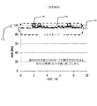
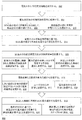
電気自動車(以下、「EV」という)の充電が始まり、充電状態値(以下、「SOC」)がSOC最小値よりも大きくなると、このEVの充電は停止する。図1は、充電中のEVのSOCについての代表的な従来技術の挙動を説明する。この従来技術では、100%というSOC最高値104に近い、95%というEVの高いSOC最小値102が車両から電力系統への(V2G)モードで設定されている。このような高いSOC最小値102の場合、充電用の動作窓112は極めて狭く、充電容量の5%しかない。EVがエネルギを蓄えることを、電力系統が要求した場合、EVのSOCはすぐにSOC最大値に到達する、またはSOC最大値を超える。EVのSOCがSOC最大値に到達するか、またはSOC最大値を超えると、EVの充電は停止し、EVを電力系統または電力使用設備のために電気エネルギを利用して蓄えることができない。言い換えれば、V2GがEVを高いSOC最小値102に保つ場合、EVのSOCは簡単にピークSOC104(例、100%)に到達する。さらに、EVのSOCをSOC最小値よりも高く維持するには、高いSOC最小値と狭い充電用の動作窓112のために、EVの充電頻度を高くする必要がある。したがって、EVを都合よく、より最適な時間にSOC最大値まで充電するという可能性が低くなる。
When charging of an electric vehicle (hereinafter referred to as “EV”) starts and a state of charge (hereinafter referred to as “SOC”) becomes larger than the SOC minimum value, charging of the EV is stopped. FIG. 1 illustrates representative prior art behavior for the SOC of an EV during charging. In this prior art, the SOC
前記した内容および後記する詳細な内容はともに代表的なものであり、説明のためのものであり、特許請求の範囲に記載した開示内容を説明するものである。 Both the contents described above and the detailed contents to be described later are representative, are for explanation, and explain the disclosed contents described in the claims.
いくつかの代表的な実施形態は、充電ステーションに接続された電気自動車に電荷を蓄える、コンピュータが実行する方法を提供する。この方法は、前記電気自動車のSOC最小値を得て、前記電気自動車をSOC最大値まで充電する時間を決定し、前記SOC最小値としきい値の間で前記電気自動車の充電および放電を繰り返して、電気自動車のSOCを前記SOC最小値としきい値の間に維持し、前記電気自動車をSOC最大値まで充電する決定した時間が過ぎたら、前記電気自動車をSOC最大値まで充電するものであり、前記しきい値は前記SOC最小値よりも大きく、前記SOC最大値以下である。 Some exemplary embodiments provide a computer-implemented method for storing charge in an electric vehicle connected to a charging station. The method obtains the SOC minimum value of the electric vehicle, determines a time for charging the electric vehicle to the SOC maximum value, and repeatedly charges and discharges the electric vehicle between the SOC minimum value and a threshold value. Maintaining the SOC of the electric vehicle between the SOC minimum value and a threshold value and charging the electric vehicle to the SOC maximum value after a determined time has passed to charge the electric vehicle to the SOC maximum value; The threshold value is greater than the SOC minimum value and less than or equal to the SOC maximum value.
いくつかの代表的な実施形態は、充電ステーションに接続された電気自動車に電荷を蓄える、自動車システムを提供する。このシステムは、充電ステーションにより提供された電気エネルギの情報を特定するテレマティクス−ナビゲーション装置と、前記電気自動車を最低充電状態値(SOC)にする制御ユニットとを含み、前記電気自動車をSOC最大値まで充電する時間を決定し、前記SOC最小値としきい値の間で前記電気自動車の充電および放電を繰り返して、電気自動車のSOCを前記SOC最小値としきい値の間に維持し、前記電気自動車をSOC最大値まで充電する決定した時間が過ぎたら、前記電気自動車をSOC最大値まで充電するものであり、前記しきい値は前記SOC最小値よりも大きく、前記SOC最大値以下である。 Some exemplary embodiments provide an automotive system that stores charge in an electric vehicle connected to a charging station. The system includes a telematics-navigation device that identifies information on electrical energy provided by a charging station, and a control unit that places the electric vehicle in a minimum state of charge (SOC), the electric vehicle up to a SOC maximum value. The charging time is determined, and the electric vehicle is repeatedly charged and discharged between the SOC minimum value and the threshold value to maintain the SOC of the electric vehicle between the SOC minimum value and the threshold value. When the determined time for charging to the SOC maximum value has passed, the electric vehicle is charged to the SOC maximum value, and the threshold value is greater than the SOC minimum value and less than or equal to the SOC maximum value.
本願発明の追加的な特徴は、後記する発明を実施するための形態に記載され、さらに同発明を実施するための形態の記載から明らかであり、本願発明を実施することによりわかるはずである。 Additional features of the present invention will be described in the modes for carrying out the invention to be described later, and will be apparent from the description of the modes for carrying out the invention, and should be understood by carrying out the present invention.
添付した図面は、本願開示内容をさらによく理解できるようにし、本明細書と合体し、本明細書の一部を構成するものであり、本願開示内容の実施形態を図示し、本明細書とともに本願開示内容の原理を説明するのに役立ちます。データフロー図が、システム内に情報が入る、情報がシステムから出ていく、さらにシステム内である場所から別の場所に移ることを観念的に表わす場合、システム内の複数のモジュールまたは複数のプロセスにより異なる要素が動作するものでよい。さらにこれらのモジュールのデータが他のモジュールに移るものでよい。 The accompanying drawings are included to provide a better understanding of the present disclosure, and are incorporated into and constitute a part of this specification, and illustrate embodiments of the present disclosure together with the present specification. It helps to explain the principles of this disclosure. Multiple modules or multiple processes in a system when the data flow diagram conceptually represents information entering the system, information exiting the system, and moving from one location to another in the system Different elements may be operated depending on. Further, the data of these modules may be transferred to other modules.
代表的な本願発明の実施形態を示す添付した図面を参照して、本願発明の実施形態について以下詳細に記載する。しかしながら、本願発明は様々な多くの形態で具現化されうるものであり、以下に記載する実施形態に限定して解釈してはいけない。むしろ、これらの代表的な実施形態は、以下の本願発明の実施形態の説明が包括的なものであり、本願発明の技術的範囲を当業者に完全に伝えるものである。以下の本願発明の実施形態の説明のために、「X、YおよびZのうちの少なくとも一つ」は、Xのみ、Yのみ、Zのみ、または2つまたはそれより多い要素X,YおよびZの組み合わせ(例、XYZ,XZ,XYY,YZ、ZZ)と解釈される。すべての図面および詳細な説明にわたって、記載されないかぎり、同一の図面符号は、同一の要素、特徴および構造を指す。これらの要素の相対的な大きさや描写は明確にするために強調されている。 Embodiments of the present invention will be described in detail below with reference to the accompanying drawings showing representative embodiments of the present invention. However, the present invention can be embodied in many different forms, and should not be interpreted as being limited to the embodiments described below. Rather, these exemplary embodiments are comprehensive of the following description of the embodiments of the present invention, and fully convey the technical scope of the present invention to those skilled in the art. For the following description of embodiments of the present invention, “at least one of X, Y and Z” means X only, Y only, Z only, or two or more elements X, Y and Z. (For example, XYZ, XZ, XYY, YZ, ZZ). Throughout the drawings and detailed description, unless otherwise described, the same drawing reference numerals refer to the same elements, features and structures. The relative size and depiction of these elements are emphasized for clarity.
本明細書で用いる語句は、特定の実施形態を記載するためのものであり、本願発明を限定することを意図したものではない。本明細書で用いている、単数形の「a」、「an」および「the」は、文脈から特に明示されていないかぎり複数形も含む。さらに、「a」、「an」といった語句を用いることは量を限定することを表すものではなく、言及されるものが少なくとも一つあることを表す。また、「first」、「second」等の語を用いることは、いかなる特別な順番や重要性を意味するものではなく、個々の要素を他の要素と区別するために用いている。本明細書において、「comprises」、「comprising」、または「includes」および/あるいは「including」が用いられている場合、言及している特徴、領域、ステップ、作業、要素、および/または部品が存在することを特定するが、それら以外の特徴、領域、ステップ、作業、要素、および/または部品が存在することを除外しない。特徴の中には個別の実施形態に関して記載されているものもあるが、発明の実施態様はそのような特徴に限定される必要はなく、一つ以上の代表的な実施形態に含まれる特徴は一つ以上の代表的な実施形態に含まれる他の特徴と組み合わせることも可能である。 The terminology used herein is for the purpose of describing particular embodiments and is not intended to be limiting of the invention. As used herein, the singular forms “a”, “an”, and “the” include plural referents unless the context clearly dictates otherwise. Furthermore, the use of the phrases “a”, “an” does not represent a limitation of quantity, but does indicate that there is at least one mentioned. The use of words such as “first” and “second” does not imply any special order or importance, but is used to distinguish individual elements from other elements. Where "comprises", "comprising", or "includes" and / or "inclusioning" is used herein, the feature, region, step, operation, element, and / or part referred to is present Does not exclude the presence of other features, areas, steps, operations, elements, and / or parts. Although some of the features are described in terms of individual embodiments, the embodiments of the invention need not be limited to such features, and the features included in one or more exemplary embodiments are: Combinations with other features included in one or more exemplary embodiments are also possible.
これから、図面を参照して実施形態を説明する。図面において、同じ参照番号は同一の要素または機能が同じ要素を示す。本明細書中で「一つの実施形態」または「一実施形態」という場合、すべての実施形態に関して記載された特徴、構造または特質が少なくとも一つの実施形態に含まれていることを意味する。「一つの実施形態中」というフレーズが本明細書中の様々な箇所に現れる場合、必ずしも同じ実施形態を指しているわけではない。 Embodiments will now be described with reference to the drawings. In the drawings, like reference numbers indicate identical elements or elements having the same function. Reference herein to "one embodiment" or "one embodiment" means that at least one embodiment includes a feature, structure, or characteristic described with respect to all embodiments. Where the phrase “in one embodiment” appears in various places in the specification, it does not necessarily refer to the same embodiment.
後記する発明の詳細な説明のいくつかの部分は、コンピュータメモリ内部のデータビットの操作に関するアルゴリズムと符号表現により記載されている。これらのアルゴリズムの説明および表現は、当業者が用いて、自分の仕事の概要を他の当業者に伝えることが多い。本明細書では、また一般的に、アルゴリズムは自己矛盾のない連続した複数のステップであり、所望の結果につながるものである。このようなステップは物理量を物理的に操作するステップ(指令)である。必ずというわけではないが、通常このような物理量は、保存し、移送し、組み合わわせ、比較し、さもなければ操作することが可能な電気信号、磁気信号、または光学信号の形式である。これらの信号をビット、値、要素、シンボル、文字、語、数字等と呼ぶのが便利な場合がある。さらに、物理量の操作を必要とする複数のステップを配置することをモジュールまたはコード装置と呼ぶこともまた便利なことがあり、一般性を失うことがない。 Some portions of the detailed description of the invention that follow are described in terms of algorithms and code representations relating to the manipulation of data bits within a computer memory. These algorithmic descriptions and representations are often used by those skilled in the art to provide an overview of their work to others skilled in the art. As used herein, and generally, an algorithm is a sequence of steps that are self-consistent and lead to a desired result. Such a step is a step (command) for physically manipulating the physical quantity. Usually, though not necessarily, such physical quantities are in the form of electrical, magnetic, or optical signals that can be stored, transported, combined, compared, and otherwise manipulated. It may be convenient to refer to these signals as bits, values, elements, symbols, characters, words, numbers, and the like. Furthermore, it may also be convenient to call multiple steps that require manipulation of physical quantities called modules or code devices, without losing generality.
しかしながら、これらの語句や類似した語句のすべては、適切な物理量と結びついたものであり、これらの物理量に付けられる便利なラベルにすぎない。後記する説明から明らかなように特に指示がないかぎり、本明細書全体にわたって、「processing」、「computing」、「determining」または「displaying」といった語句は、コンピュータシステムのメモリあるいはレジスタまたは他の情報格納部、情報伝達部あるいは情報表示装置の内部で物理量(電気量)として表わされるデータを操作し、変形させる他のコンピュータシステムまたは同様な電子計算装置の動作およびプロセスを指す。 However, all of these and similar phrases are associated with appropriate physical quantities and are merely convenient labels attached to these physical quantities. Throughout this specification, the terms “processing”, “computing”, “determining”, or “displaying” refer to memory or registers in a computer system or other information storage, unless otherwise indicated, as will be apparent from the description below. Refers to the operation and process of another computer system or similar electronic computing device that manipulates and transforms data represented as physical quantities (electrical quantities) within a computer, information transmission unit, or information display device.
本願発明の実施形態の特徴には、アルゴリズムの形式で記載されたプロセスステップおよび指令が含まれる。本願発明の実施形態のこのようなプロセスステップおよび指令は、ソフトウェア、ファームウェア、またはハードウェアにより具現化され、ソフトウェアにより具現化される場合、様々なオペレーティングシステムによって用いられるいろんなプラットフォームにダウンロードされ、それらプラットフォームから指令を出すことにしてもよい。 Features of embodiments of the present invention include process steps and instructions described in the form of an algorithm. Such process steps and instructions of embodiments of the present invention are implemented in software, firmware, or hardware, and when implemented in software, are downloaded to various platforms used by various operating systems, and the platforms The command may be issued from
本願発明の実施形態は、さらに同実施形態の作業を行う装置に関する。この装置は必要な目的のために作製されるものでもよいし、コンピュータに記憶されるコンピュータプログラムによって選択的に起動し、再構成される汎用コンピュータでもよい。そのようなコンピュータプログラムとして、フロッピー(登録商標)ディスク、光学ディスク、CD−ROM,磁気光学ディスク、リードオンリーメモリ(ROM)、ランダムアクセスメモリ(RAM)、EPROM、EEPROM、磁気または光学カード、カスタムIC(ASIC)、または電子指令を記憶するのに適した任意の媒体を含むコンピュータバスに接続した任意のディスクのような不揮発性のコンピュータが読み取り可能な媒体をもちいてもよい。ただし、これらの媒体に限定するものではない。 The embodiment of the present invention further relates to an apparatus for performing the operation of the embodiment. This device may be made for the required purpose, or it may be a general purpose computer that is selectively activated and reconfigured by a computer program stored in the computer. Such computer programs include floppy disk, optical disk, CD-ROM, magneto-optical disk, read only memory (ROM), random access memory (RAM), EPROM, EEPROM, magnetic or optical card, custom IC. (ASIC) or any non-volatile computer readable medium such as any disk connected to a computer bus including any medium suitable for storing electronic instructions may be used. However, the present invention is not limited to these media.
本明細書で提示するアルゴリズムおよびディスプレイは、もともと特定のコンピュータや他の装置に関係するものではない。様々な汎用システムを本明細書の開示内容にしたがうプログラムとともに用いることができるし、必要な方法ステップを実行するもっと専用の装置を作製することが便利かもしれない。様々なこのようなシステムに必要な構造は、以下の記載に現れる。さらに、本願発明の実施形態は、特定のプログラミング言語を参照して説明されてはいない。本願発明の実施形態の内容を実行するには、様々なプログラミング言語を用いることができる。以下の説明における特定の言語に対する言及は、実施可能性と本願発明の実施形態のベストモードとを示すためになされたものである。 The algorithms and displays presented herein are not inherently related to any particular computer or other device. Various general purpose systems can be used with programs in accordance with the disclosure herein, and it may be convenient to create a more specialized device that performs the necessary method steps. The required structure for a variety of such systems will appear in the description below. In addition, embodiments of the present invention are not described with reference to a particular programming language. Various programming languages can be used to implement the contents of the embodiments of the present invention. References to specific languages in the following description are made to show feasibility and best mode of embodiments of the present invention.
さらに、本明細書でも散られる言語は、主として理解しやすさと説明の目的で選ばれたものであり、本願発明の主題を詳細に説明し、その範囲を限定する場合には選択しなかったかもしてない。したがって、明細書中の本願発明の実施形態は、実例であって本願発明の実施形態の範囲を限定するものではない。本願発明の実施形態の範囲は、特許請求の範囲で説明される。 In addition, the language scattered in this specification was chosen primarily for ease of understanding and explanation, and may not have been selected to describe the subject matter of the present invention in detail and to limit its scope. Not. Accordingly, the embodiments of the present invention in the specification are illustrative and do not limit the scope of the embodiments of the present invention. The scope of the embodiments of the present invention is described in the claims.
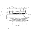
図2は、本願発明の一実施形態にしたがう代表的なEVの充電および放電の状態変化を図示する。グラフ200は、EVが例えば車両−電力系統結合モード(V2G)で充電されている時のEV用の代表的な充電サイクルを図示する。典型的な図2から、EVは時間0において充電レベル214(約95%)となっている。EVが約95%の充電レベル214の状態で充電機に接続されると、EVは、放電することにより、または電力系統に電力を供給することにより、SOC最小値レベル202まで放電できる。また、EVのSOCがSOC最小値レベル202よりも低い状態でEVが時間0で充電機に接続されると、EVはそのSOCがSOC最小値202以上になるまで充電機により充電される。
FIG. 2 illustrates a typical EV charge and discharge state change according to one embodiment of the present invention.
EVは、例えば、時計のようなEVの様々な部品が電力を必要とするため、走行中でない時も放電する。EVのSOCがSOC最小値レベルを超えると、EVは小さいSOCの変化量で充電および放電を行う。この小さい変化量の充電および放電によって、図2に図示する充電状態の小変動または微小変動206による波形にしたがう振幅の速い変化となっている。
The EV is discharged even when it is not running because various parts of the EV such as a watch require electric power. When the SOC of the EV exceeds the SOC minimum value level, the EV is charged and discharged with a small SOC change amount. Due to the small amount of change in charge and discharge, the amplitude changes rapidly according to the waveform due to the small or
EVのSOC最大値レベル204は、例えば、100%、95%、90%等になる。電力系統の配電業者は、EVの充電容量を利用して動作窓212にかかる余剰エネルギ208を蓄える。動作窓212は、フロートまたは範囲と呼んでもよい。代表的な実施形態では、動作窓212がSOC最小値212としきい値の間のEVの蓄電能力を含む。電力系統の電力供給が過大になった時は、電力系統から供給される交流電流の周波数が高くなり、電力系統は不安定になる。したがって、電力系統の配電業者は、この余剰エネルギを放出(放電)したり、蓄電したりする。余剰エネルギをEVに蓄電することにより、エネルギの無駄を最小にすることができる。
The EV SOC
代表的な実施形態では、SOC最小値202は従来技術のSOC最小値が95%であるのに比べて低くなっており、例えば60%まで低くされている。SOC最小値202を低くすることによって、SOC最大値204とSOC最小値202の間の動作窓212が大きくなる。大きくなった動作窓212により、電力系統の配電業者はEVの充電能力を用いて、余剰エネルギを長期間蓄電することができる。代表的な実施形態では、動作窓212は、SOC最小値202とSOC最大値204の間の全範囲に設定することができる。代表的な実施形態では、動作窓212は、SOC最小値202とSOC最大値204の間の範囲の一部としてもよい。例えば動作窓212を、60%のSOC最小値202と100%のSOC最大値204より小さい所定のしきい値の間の20%としてもよい。この場合、動作窓212のしきい値220は80%のSOCに設定される。
In an exemplary embodiment, the SOC
動作窓212内にあるSOCは、電力系統の余剰エネルギ208を蓄電する機会を提供して、電力系統を安定化させるために用いられ、または役立っている。すなわち、電力系統の発電能力がSOC最小値レベル202を超えた場合に、動作窓212によって電力系統からの余剰電荷を吸収して電力系統を安定化させる。
The SOC within the operating
SOC最小値202は所定の状況になった場合の移動に必要な量に設定してよい。例えば、ユーザーが緊急時に病院に行く、または地域の商店に/から移動する場合である。通常の状況以外で運転者が運転する状況によっては、異なるSOC最小値レベル202を用いることができる。
The SOC
EVのSOC最小値レベル202は、車両、車両ユーザ、配電業者またはこれらの組み合わせによって決定されるものでよい。EVのSOC最大値レベル204は、車両、車両ユーザー、配電業者、またはこれらの組み合わせによって決定されるものでよい。車両保有者は、自分の車両を蓄エネルギに使用させることに対する対価を得る。
The EV SOC
代表的な実施形態では、従来よりも低いSOC最小値202を設定することによって、従来の高いSOC最小値202(図1参照。前記した95%という高いSOC最小値につき図示されている。)ではなく、EVを例えば60%という従来よりも低いSOC最小値202に一日のうちの所定時間まで、例えば真夜中まで放電させることが可能である。SOC最小値202までは停止中の車両を放電可能であり、このSOC最小値202を低くすることによって、V2Gシステムではより大きな充電窓が与えられる。例えば、前記したようにSOC最小値202を例えば60%に設定し、SOC最大値204を例えば80%に設定する場合、EVは従来技術より大きい動作窓212が与えられる。したがって、SOC最小値202が95%で、SOC最大値204が100%で、動作窓が5%にすぎない場合の5%の動作窓ではなく、20%の動作窓でEVは稼働する。大きな動作窓の状態ならば、EVが充電する頻度は少なくて済む。充電頻度が減少すれば、EVが充電する時間をより最適な時間にすることができる。例えば、EVユーザーの光熱費が安い時や停電/節電が差し迫っている時間ではなく、実行されてもいない時等である。
In an exemplary embodiment, by setting a lower SOC
SOC最小値202になると車両の充電を開始し、動作窓212により設定される上限のSOCまで、例えば図2に示すSOC最小値202よりも20%より高いSOCまで充電し、EVのSOCをSOC最小値202よりも高く保つために実行する充電サイクルの頻度を減らす。EVをSOC最大値204にまで充電する所定の時間210になると、EVを充電して時間216にSOC最大値204になる。
When the SOC
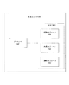
図3は本願発明の一実施形態にしたがう典型的な車両の通信環境を図示する。図3は無線通信ネットワーク316により接続されている電気自動車(EV)302、追跡探知サーバー312および電力会社サーバー314を含む車両通信環境300を図示する。
FIG. 3 illustrates a typical vehicle communication environment according to one embodiment of the present invention. FIG. 3 illustrates a
EV302は、車両302を駆動する電気モータ(図示せず)を含む。代表的実施形態では、EV302は1機以上電気モータによって駆動されるものでよい。代表的実施形態では、EV302は1機以上電気モータと別のエンジン、例えば内燃機関エンジンまたはプラグインハイブリッド車両によって駆動されるものでよい。
EV302の1機以上の電気モータ、車両302に搭載された二次電池(図示せず)によって電力供給される。この車載二次電池は、EV302が充電ステーション310に接続または結合されると充電される。代表的な実施形態では、EV302は充電ケーブル318を介して充電ステーション310に接続される。代表的な実施形態では、例えばEV302を充電ステーション310に隣接させると、または充電ステーション310の近傍に配置すると無線充電される。充電ステーション310は、例えばEV302の二次電池を充電して、または再充電させて、EV302に電気エネルギを与える。電力会社から電力系統を介して電気エネルギが充電ステーション310に供給される。代表的な実施形態では、充電ステーション310は110/120V回路、220/240V回路またはさらに高い電圧の回路に接続されるものでよい。代表的な実施形態では、充電ステーション310はEV302の所有者の自宅に置かれるものでよい。代表的な実施形態では、充電ステーション310は、例えばショッピングセンタ、仕事場、充電施設等の公共の場所に置かれるものでよい。代表的な実施形態では、前記した車載二次電池は回生ブレーキを用いて充電してもよい。
Power is supplied by one or more electric motors of the
EV302は、EV302の充電を管理する充電システム304を含む。充電システム304は、テレマティクスナビゲーション装置306と制御ユニット308とを含む。テレマティクスナビゲーション装置306は、テレマティクスナビゲーション装置306のユーザおよび無線通信ネットワーク316に接続された構成要素と情報交換する。テレマティクスナビゲーション装置306は、EV302が充電ステーション306と接続されている時に充電指令をユーザから受信するものでよい。EV302を充電するモードおよび手順は複数あってよい。テレマティクスナビゲーション装置306は、電力会社サーバー314と通信して、電気エネルギの価格、エネルギが再生エネルギ源(例、太陽光、風または波)用いて製造されたものか等といった電気エネルギについての情報を取得する。EV302が充電されている時、テレマティクスナビゲーション装置306は追跡探知サーバー312に充電情報を提供することができる。
制御ユニット308は、EV302の充電制御を行う。EV302の充電には、EVの二次電池の充電を含む。EV302が充電ステーション310と接続されている時、ユーザーが選択した充電モードに基づいて、制御ユニット308はEV302を充電する手順を決定する。この決定した手順にしたがって、制御ユニット308はEV302を充電する。
The
代表的な実施形態では、ユーザは「経済的」充電モードを選択できる。この経済的充電モードでは、制御ユニット308は電気エネルギを充電ステーション310からEV302に流して、EV302の充電を開始させる。制御ユニット308は電気エネルギの価格に関わらず充電を開始させてもよい。本明細書で用いられている「充電状態値」という語は、EVの二次電池に蓄えられている電荷/電気エネルギの量を指す。いったん最低充電状態値になると、制御ユニット308は、充電ステーション310からEV302への電気エネルギの流れを止めて、EV302の充電を停止する。オフピーク時間帯のように電気エネルギの価格が安い時に、制御ユニット308はEV302の充電を再開する。
In an exemplary embodiment, the user can select an “economic” charging mode. In this economical charging mode, the
ユーザによって、または例えば使用パターンに基づき制御ユニット308によって、最低充電状態値は決定されてよい。最低充電状態値は、例えば近くの雑貨店に行き、お使い等をして、自宅まで帰ってくるのに十分間に合うように設定される。経済的モードの一つの有利な点は、電気エネルギが安い時に大部分の充電がなされる一方、運転者が立ち往生するのを防ぐための充電をEV302が受けることである。
The minimum state of charge value may be determined by the user or by the
代表的な実施形態では、ユーザは「グリーン」充電モードを選択することができる。グリーンモードは、充電ステーション310に提供される電気エネルギが再生エネルギ源を用いて製造されたエネルギの時に、制御ユニット308がEV302の充電を再開させることを除けば経済的モードと同じである。
In an exemplary embodiment, the user can select a “green” charge mode. The green mode is the same as the economic mode except that the
電力会社サーバー314は、電気エネルギについての情報を様々な構成要素に与える。代表的な実施形態では、EV302からの要求があると、電力会社サーバー314は、電力会社から供給される電気エネルギについて特定する情報をEV302に送信する。代表的な実施形態では、EV302からの要求によりEV302に電力会社サーバー314から送信される情報には、電力会社からオフピーク価格で電気エネルギが提供される期間、同電気エネルギが再生エネルギ源によって製造される期間等の格付け情報を含む。
The
代表的な実施形態では、EV302に送信される情報には、電気エネルギの価格情報が含まれる。代表的な実施形態では、価格情報は電気エネルギの価格が、時間、日、月および/または季節によって変化する時間帯別料金である。例えば、夏季の月の間の電気エネルギの価格情報は、ピーク時(例、午後0時から午後7時)が0.14ドル/kWh、部分ピーク時(例、午前10時から午後0時および午後7時から午後10時)が0.07ドル/kWh、および非ピーク時(午前0時から午前10時および午後10時から午後11時59分)が0.03ドル/kWhとすることができる。
In an exemplary embodiment, the information transmitted to
代表的な実施形態では、EVを所有し、追跡探知サーバー312にEVの充電を制御させることに対する特別料金を、EV302の所有者に電力会社が提示する。そのため、電力会社サーバー314が受信するEV302からの要求には、EV302に関する情報(例、車両識別番号)を特定して、さらに/またはその所有者の情報(例、所有者の名前または住所)を特定し、電力会社サーバー314が正確な価格情報をEV302に提供する。
In an exemplary embodiment, the utility company offers the
代表的な実施形態では、電力会社サーバー314は追跡探知サーバー312から複数の区域の総電気エネルギ蓄電能力を求める要求を受信する。要求された区域の各々に対して、電力会社サーバー314はその区域の現在の総電気エネルギ蓄電能力を追跡探知サーバー312に送信する。一つの区域の総電気エネルギ蓄電能力には、その区域内のすべてのEVから利用可能な総電気エネルギの蓄積量が含まれる。構成要素には、充電ステーション、家および企業が含まれる。代表的な実施形態では、電力会社サーバー314はさらに各区域の総電気エネルギ消費量および/または総蓄電能力についての情報をEV302に送信する。
In the exemplary embodiment,
代表的な実施形態では、電力会社サーバー314は電力会社が維持している。代表的な実施形態では、電力会社サーバー314は1社以上の電力会社から情報を受け取る第三者が維持する。
In the exemplary embodiment, the
無線通信ネットワーク316は、EV302と、追跡探知サーバー312と、電力会社サーバー314との間の通信経路を表す。代表的な実施形態では、無線通信ネットワーク316は、複数の基地局、複数の制御機および複数の切り替え要素と、複数のゲートウェイを含むコアネットワークとを含む移動体通信ネットワークである。代表的な実施形態では、無線通信ネットワーク316は、限定された地域にわたる無線通信を提供する無線ローカルエリアネットワーク(WLAN)である。代表的な実施形態では、このWLANは該WLANをインターネットに接続するアクセス点を含む。
The
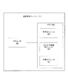
テレマティクスナビゲーション装置306は、プロセッサ402と、入力装置404と、出力装置406と、送受信装置408と、位置検知装置410と、メモリ412とを含む。
The
プロセッサ402はデータ信号を加工し、複合命令セットコンピュータ(CISC)アーキテクチャ、縮小命令セットコンピュータ(RISC)アーキテクチャ、または命令セットの組み合わせを実行するアーキテクチャを含む、様々な計算アーキテクチャを含む。図4には単一のプロセッサのみ図示されているが、複数のプロセッサが含まれていてもよい。プロセッサ402は、計算論理ユニット、マイクロプロセッサ、汎用コンピュータ、またはメモリ412、入力装置404、出力装置406、送受信装置408、もしくは位置検知装置410からの電子データ信号を発信し、受信し、さらに加工する他の情報機器を含む。
The processor 402 processes data signals and includes a variety of computing architectures, including a complex instruction set computer (CISC) architecture, a reduced instruction set computer (RISC) architecture, or an architecture that executes a combination of instruction sets. Although only a single processor is shown in FIG. 4, a plurality of processors may be included. The processor 402 sends, receives, and further processes electronic data signals from a computational logic unit, microprocessor, general purpose computer, or memory 412, input device 404, output device 406,
入力装置404は、ユーザの入力をテレマティクスナビゲーション装置306に与えるように構成されている。代表的な入力装置404は、カーソルコントローラ、キーボード、タッチスクリーン装置、マイクロフォン、触覚フィードバック装置、または同等物を含むものでよい。代表的な実施形態では、入力装置404は、情報および/またはコマンドの選択をプロセッサ402またはメモリ412に伝えるように構成された、クワーティキーボード、キーパッド、またはタッチスクリーン上に作られたキーパッドの表示のような英数字の入力装置を含むものでよい。入力装置404は、画像の動きを調整させる、ジョイスティック、トラックボール、スタイラス、ペン、タッチスクリーン、カーソル方向キー、または同等物を含むものでよい。
The input device 404 is configured to provide user input to the
出力装置406は、本明細書中で説明される電子画像およびデータを表示するように構成された装置を含むものでよい。出力装置406は、例えば、有機発光ダイオード表示装置(OLED)、液晶表示装置(LCD)カソード線管(CRT)表示装置、または同等物を含むものでよい。代表的な実施形態では、出力装置406は、出力装置406のスクリーン上に配置された、または出力装置406のスクリーンと一体になった透明なパネルカバーを含むタッチ感応画面を含むものでよい。代表的な実施形態では、出力装置406は、本明細書で説明される音を出力するスピーカを含むものでもよい。 Output device 406 may include a device configured to display electronic images and data as described herein. The output device 406 may include, for example, an organic light emitting diode display (OLED), a liquid crystal display (LCD) cathode ray tube (CRT) display, or the like. In an exemplary embodiment, the output device 406 may include a touch-sensitive screen that includes a transparent panel cover disposed on or integral with the screen of the output device 406. In an exemplary embodiment, the output device 406 may include a speaker that outputs sound as described herein.
送受信装置408は、無線通信ネットワーク316と接続された構成要素と通信するように構成された装置を含む。代表的な実施形態では、テレマティクスナビゲーション装置306は、追跡探知サーバー312および電力会社サーバー314のような遠くにあるシステムまたは装置と通信する送受信装置408を用いる。
The
位置検知装置410は、測位衛星(例、地球位置決めシステム(GPS)衛星)と通信し、EV302の地理上の位置を決定するように構成された装置を含む。代表的な実施形態では、位置検知装置410は、3機、4機またはもっと多いGPS衛星からのGPS情報またはGPS信号を検索し、集めてEV302の位置を決定する。各信号の一斉送信時間と受信時間の時間間隔を用いて、位置検知装置410はEV302と各GPS衛星との距離を計算できる。これらの複数の距離測定と衛星位置と時間の情報とによって、位置検知装置410は、EV302の地理上の位置および/または向きを計算し、決定する。
メモリ412はプロセッサ402が実行する指令および/またはデータを記憶する。このような指令および/またはデータは本明細書中で説明する任意のまたはすべての技術事項を実行するためにコード化されたものでよい。メモリ412はダイナミックランダムアクセスメモリ(DRAM)素子、スタティックランダムアクセスメモリ(SRAM)素子、フラッシュRAM(不揮発性記憶媒体)素子、上記メモリ素子の組み合わせ、または他の従来技術のメモリ素子とすることができる。メモリ412は、インタフェースモジュール414、エネルギモジュール416、方向指示モジュール418および範囲モジュール422を記憶することができる。これらのモジュールはすべてプロセッサ402、入力装置404、出力装置406、送受信装置408および/または位置検知装置410と通信できる。
Memory 412 stores instructions and / or data executed by processor 402. Such instructions and / or data may be coded to perform any or all of the technical matters described herein. The memory 412 can be a dynamic random access memory (DRAM) element, a static random access memory (SRAM) element, a flash RAM (nonvolatile storage medium) element, a combination of the above memory elements, or other prior art memory elements. . The memory 412 can store an interface module 414, an energy module 416, a direction indication module 418 and a
インタフェースモジュール414は、テレマティクスナビゲーション装置306の複数のユーザと通信する。インタフェースモジュール414は、EV302が充電ステーション310と接続されると、EV302を充電するモード選択をユーザ(例、EVの運転者またはEVの乗客)から受信する。ユーザが選択できるモードには、一つ以上の次のモードを含めてよい。「即時充電」モード、「経済的」モード、「タイマー」モード、および「グリーン」モード。
Interface module 414 communicates with a plurality of users of
即時充電モードのときは、EV302が一旦充電ステーション310に接続されると、即座にEV302の充電を開始し、EV302が完全に充電されるまでEV302の充電が続く。タイマーモードのときは、ユーザはインタフェースモジュール414に充電を開始する時間を与える。与えられた時間に、EV302の充電が開始される。
In the immediate charge mode, once the
前記した経済的モードのときは、EV302は最低充電状態値まで充電される。一旦、最低充電状態値まで充電されると、充電は停止する。代表的な実施形態では、最低充電状態値はEVの製造者により設定される(例、10パーセント、20パーセント、16km、32km、48km、96km走行するのに十分な量等)。代表的な実施形態では、ユーザがインタフェースモジュール414に最低充電状態値を与える。電気エネルギが安い時に充電が再開される。代表的な実施形態では、電気エネルギが安いのは電気エネルギの価格がピーク時よりも低い時である(例えば、部分ピーク時間帯またはオフピーク時間帯の価格)。ピーク時間帯は電力系統に対する電気エネルギの需要が最も高い時である。代表的な実施形態では、電気エネルギが安いのは電気エネルギの価格がオフピーク時の価格の時である。代表的な実施形態では、電気エネルギが安いとユーザが考える価格範囲をユーザがインタフェースモジュール414に与えるか、インタフェースモジュール414に電気エネルギが安いと考えられる価格範囲をユーザが設定する。
In the economic mode described above, the
グリーンモードのときは、EV302は最低充電状態値まで充電され、充電はそこで停止する。充電ステーション310に供給される電気エネルギが再生エネルギ源を用いて製造されたものである時、充電が再開される。
When in the green mode, the
代表的な実施形態では、インタフェースモジュール414は入力装置404および出力装置406を介して、ユーザと通信する。代表的な実施形態では、無線通信ネットワーク316に繋がるユーザの移動体通信装置を介してユーザと通信することができる。例えば、移動体通信装置はユーザに充電モードを選択させ、各モードの設定を提供するアプリケーションを含むものでもよい。移動体通信装置はインタフェースモジュール414にユーザのモード選択と選択モードの設定を送信する。
In the exemplary embodiment, interface module 414 communicates with the user via input device 404 and output device 406. In an exemplary embodiment, the user can communicate with the user via the user's mobile communication device connected to the
エネルギモジュール416は、電気エネルギについての情報を電力会社サーバー314から取得する。代表的な実施形態では、エネルギモジュール416が電力会社サーバー314から取得する情報には、電気エネルギの価格情報、電気エネルギが再生エネルギ源を用いて製造される時間帯、一つ以上の区域の総電気エネルギ消費、または一つ以上の区域の総電気エネルギ蓄電能力が含まれる。代表的な実施形態では、エネルギモジュール416が取得する電気エネルギの価格情報には、電気エネルギの現在の時間帯別料金が含まれる。
The energy module 416 obtains information about electrical energy from the
代表的な実施形態では、エネルギモジュール416は周期的に電力会社サーバー314に電気エネルギ情報を要求する。例えば、毎日、月に1回、またはカレンダーの季節ごとに1回、情報が請求される。代表的な実施形態では、EV302が充電ステーション310に接続されると、必ずエネルギモジュール416は電気エネルギ情報を電力会社サーバー314に要求する。エネルギモジュール416はが電力会社サーバー314から電気エネルギ情報を受け取ると、エネルギモジュール416はその受け取った情報を制御ユニット308に提供できる。
In the exemplary embodiment, energy module 416 periodically requests electrical energy information from
方向指示モジュール418は、EV302のユーザに目的地までの走行方向を与える。ユーザから目的地までの方向を求める要求を受け取ると、方向指示モジュール418は位置検知装置410からEV302の現在の地理上の位置を取得する。方向指示モジュール418は、地図データベース420に記憶されている一つ以上の地図を用いて、EV302の現在の位置から目的地までのルートを特定する。
The direction instruction module 418 gives the user of the
範囲モジュール422は、EV302の走行範囲を決定する。このEV302の範囲には、EV302がエネルギを使い切るまでに走行する距離を含むものでよい。
図5は、本願発明の一実施形態にしたがう典型的な充電ユニットを図設する。制御ユニット308は、プロセッサ502とメモリ504を含む。代表的な実施形態では、プロセッサ502とメモリ504は、テレマティクスナビゲーション装置306のプロセッサ402とメモリ412と同じ機能を有するものでよい。メモリ504は情報モジュール506、充電モジュール508および通知モジュール510を含むものでよい。
FIG. 5 illustrates an exemplary charging unit according to an embodiment of the present invention. The
情報モジュール506は充電情報を追跡探知サーバー312に与える。代表的な実施形態では、EV302が充電ステーション310に接続されると、情報モジュール506は周期的に(例、15分ごとに)充電情報を追跡探知サーバー312に送信する。代表的な実施形態では、EV302が充電を開始した時および充電が停止した時に、情報モジュール506は充電情報を追跡探知サーバー312に送信する。情報モジュール506によって追跡探知サーバー312に送信される充電情報は次の事項のうちの一つ以上を含む。現在時間、充電開始時間、充電停止時間、EV302の地理上の現在位置、EV302の車両登録番号、EVの所有者についての情報(例、所有者の識別番号、名前、または住所)、充電ステーションについての情報(例、充電ステーションでの電圧)、電流の流れ、EV302の現在の充電状態値、上記事項の組み合わせ。
Information module 506 provides charging information to tracking
充電モジュール508は、EV302の充電を管理する。EV302が充電ステーションに接続されて充電される時、少なくともユーザがテレマティクスナビゲーション装置306を介して選択する充電モードに基づいて、充電モジュール508はEV302を充電する手順を決定する。
The
即時充電モードが選択された場合、充電モジュール508が決定するEV302を充電する手順には、充電モジュール508が即座にEV302に充電を開始するステップが含まれる。代表的な実施形態では、充電を開始するには、充電モジュール508が単に充電ステーション310からEV302へ電気エネルギを流す。代表的な実施形態では、充電ケーブル318は充電ステーション310とのデータ接続線を含み、充電を開始させるには、充電モジュール508が充電ステーション310に電気エネルギを伝送させる信号を充電ステーション310に送信する。同様に、EV302の充電を停止させるには、充電モジュール508が充電ステーション310に信号を送信して電気エネルギの伝送を停止させる。一旦、充電が開始すると、充電モジュール508はEV302が完全に充電されるまで、EV302の充電を続ける。EV302が充電ステーション310から離脱されるまで、充電モジュール508はEV302を完全に充電された状態に保つ。
If the immediate charging mode is selected, the procedure of charging the
タイマーモードが選択された場合、充電モジュール508が決定するEV302を充電する手順では同タイマーモードに対応しテレマティクスナビゲーション装置306に送られる設定時間が決まっている。充電モジュール508は現在時間を監視している。設定時間になると、充電モジュール508はEV302の充電を開始させる。代表的な実施形態では、EV302が完全に充電されるまで、充電モジュール508はEV302の充電を続ける。いくつかの実施形態では、停止時間がユーザからテレマティクスナビゲーション装置306に与えられると、充電モジュール508は同停止時間になるまで、またはEV302が完全に充電されるまでのいずれか早くおきる事象まで、EV302を充電させる。
When the timer mode is selected, in the procedure for charging the
経済的モードが選択された場合、充電モジュール508が決定するEV302を充電する手順は、EV302の現在の充電状態値が所定の最低充電状態値より小さいかを判断するステップが含まれる。もしも、EV302の現在の充電状態値が所定の最低充電状態値より小さい場合、電気エネルギの現在の価格にかかわらず、充電モジュール508はEV302の充電を開始させる。EV302の充電状態値が所定の最低充電状態値になると、充電モジュール508はEV302の充電を停止させる。所定の最低充電状態値は、完全に充電されたEV302の値よりも小さい。
If the economic mode is selected, the procedure for charging the
テレマティクスナビゲーション装置306によって電力会社サーバー314から取得した最新の価格情報に基づいて、充電モジュール508は充電を再開する時間を決定する。電気エネルギの価格が安い時には、充電モジュール508は直ちに充電モジュール508はEV302の充電を決定した時間に再開する。充電モジュール508は、充電ステーションから伝送される電気エネルギが安価であるかぎり、EV302が完全に充電されるまでEV302の充電を続けさせる。
Based on the latest price information acquired from the
代表的な実施形態では、充電モジュール508が追跡探知サーバー312から充電命令を受信した場合、充電モジュール508が決定する手順にしたがって充電するのではなく、追跡探知サーバー312から受信した充電命令にしたがって、充電モジュール508はEV302を充電する。言い換えれば、充電モジュール508が決定するEV302を充電する手順よりも追跡探知サーバー312から受信した指示を優先させてよいのである。
In an exemplary embodiment, when the
通知モジュール510はEV302のユーザにメッセージを送信する。代表的な実施形態では、充電モジュール508がEV302を充電する命令を追跡探知サーバー312から受信すると、通知モジュールがその命令にしたがってEV302をどのように充電するかについての情報を有するメッセージを送信する。例えば、追跡探知サーバー312から受信した命令が充電を2時間遅らせることを指示しているとき、通知モジュール510はユーザにEV302の充電を2時間遅れる旨のメッセージを送る。追跡探知サーバー312から受信した情報に基づき、通知モジュール510はさらに追跡探知サーバー312の命令にしたがってEV302を充電する理由の説明を送信するメッセージにさらに含める。例えば、この理由の説明は、EV302の余っている能力を用いて、余剰電気エネルギを蓄電することとしてよい。代表的な実施形態では、通知モジュール510がユーザにメッセージを送るのは、次の事項のうちの一つ以上がおこる場合である。充電モジュール508がEV302の充電を開始させたとき、EV302の充電が停止したとき、およびEV302が完全に充電されたとき。
The
代表的な実施形態では、通知モジュール510によってユーザの移動体通信装置に送られるメッセージは、ショートメッセージサービスまたはマルチメディアメッセージングサービス(MMS)として送られる。代表的な実施形態では、メッセージはユーザの移動体通信装置に送信され、その移動体通信装置上に、EV302についての情報を提供する移動体通信アプリケーションの一部として現れる。別の実施形態では、メッセージはeメールとしてユーザのeメールアドレスに送信される。
In an exemplary embodiment, the message sent by the
図6は、本願発明の一実施形態にしたがう典型的な追跡探知サーバーを図示する。追跡探知サーバー312は、プロセッサ602とメモリ604とを含む。代表的な実施形態では、プロセッサ602とメモリ604の機能は、テレマティクスナビゲーション装置306のプロセッサ402とメモリ412と同じである。メモリ604は、車両モジュール606とエネルギ蓄電モジュール608と手順モジュール610とを格納する。
FIG. 6 illustrates an exemplary tracking detection server according to an embodiment of the present invention. The tracking
車両モジュール606は異なる複数の区域内の充電を行っている複数のEV302を追跡探知する。車両モジュール606は各区域内にある充電中のEV302のリストを保持する。EV302が充電中であることを示す充電情報をそのEV302が送信すると、車両モジュール606はその充電情報から送信したEV302の現在の地理的位置を特定し、さらに該EV302の地理的位置に対応する区域を特定する。車両モジュール606は該EV302が前記リスト中に含まれているか否かを判定する。もしも、EV302が含まれていない場合、車両モジュール606は該EV302を特定された区域の前記リストに、受信した充電情報とともに加える(例、EVの車両識別番号)。もしも、EV302が前記リスト中に含まれている場合、車両モジュール606は、最後に受信した情報に基づいて、前記リスト中に含まれる該EV302の充電情報を更新する。例えば、該EV302の現在の充電状態値が70%であるが、前記リストでは30%になっている場合、車両モジュール606は前記リストを更新して、前記リスト中での該EV302の充電状態値を70%とする。
The vehicle module 606 tracks and tracks a plurality of
EV302の充電が停止したことを示す充電情報をEV302が送信すると、車両モジュール606はEV302の現在位置に対応する区域を特定する。車両モジュール606は特定された区域にあるこのEV302を前記リストから除く。
When
エネルギ蓄電モジュール608は、複数の区域の電気エネルギ蓄電能力を追跡探知する。エネルギ蓄電モジュール608は、各区域について、その区域が現在必要とする総電気エネルギ蓄電量を、電力会社サーバー314に周期的に(例、30分おきに)要求して、受信する。エネルギ蓄電モジュール608は、電力会社サーバー314から受信した情報に基づいて、すべての区域の各々の現在の余剰発電エネルギを追跡探知する。
The energy storage module 608 tracks and detects the electrical energy storage capability of a plurality of areas. For each zone, the energy storage module 608 periodically requests (for example, every 30 minutes) and receives the total electrical energy storage amount currently required by the zone from the
手順モジュール610は、必要な場合、複数のEVの充電をコントロールして、複数の区域に対して電気エネルギ蓄電能力を提供する。エネルギ蓄電モジュール608によって追跡探知された一つの区域の総電気エネルギ蓄電能力が、所定のしきい値よりも大きい場合、手順モジュール610はその区域で充電中の複数のEVの情報を車両モジュール606から取得する。手順モジュール610はその区域内にあるすべてのEVに電気エネルギを蓄えることができるようにその区域内のすべてのEVを効率的に充電する手順を決める。
代表的な実施形態では、手順モジュール610が決定する手順は、区域内にある1台以上のEVに、対応する充電ステーションから放出されて、蓄えられる電気エネルギの割合を小さくすることである。代表的な実施形態では、この手順は、区域内にある複数のEV302に電荷を蓄えることを遅らせて、すべてのEV302の充電状態値がEV302に設定された最大充電状態値より小さいままに保つことである。この実施形態においては、手順には手順モジュール610が区域内の各EV302をこれから充電する予定を決めることからなる。この手順は、各EV302がいつ充電されること、およびその充電時間を示す。代表的な実施形態では、充電動作窓が大きいEV302の充電時間は早くなり、比較的長い時間電気エネルギを蓄える。一方、充電動作窓が小さいEV302の充電時間は比較的遅い。代表的な実施形態では、手順モジュール610が決定するさらに思い切った手順が、区域内のすべてのEV302に電荷を蓄えることになる。
In the exemplary embodiment, the procedure determined by the
手順モジュール610は、決定した手順に基づいて、充電命令を区域内の対象となるEV302に送信する。この充電命令は各EV302に対してそのEV302の充電方法を指示する。送信された充電命令にしたがって、EV302は手順モジュール610が決定した手順を実行する。代表的な実施形態では、手順モジュール610は充電命令とともに決定した手順が実行されるべき理由に関する情報も送信する(例、現在の電気エネルギ消費量は現在の発電量より少ないから)。
The
代表的な実施形態では、各区域によりしきい値が異なる。例えば、ある区域におけるしきい値は、発電量が電力消費量よりも5%、10%、15%、20%、または20%よりも大きく上回ることである。代表的な実施形態では、各区域に対して複数のしきい値があってもよく、手順モジュール610により設定される手順は、どのしきい値を上回るかによって変わる。例えば、上回ったしきい値が区域の最大容量の5%である場合、手順モジュール610はその区域内のEVに電荷を蓄えること遅らせる。しかし、上回ったしきい値が区域の最大容量の15%である場合、手順モジュール610はその区域内のすべてのEVに電荷を蓄える。代表的な実施形態では、一つの区域の一つ以上のしきい値はその区域に電力エネルギを提供する電力会社が設定する。
In the exemplary embodiment, the threshold value is different for each zone. For example, a threshold in an area is that the amount of power generated is 5%, 10%, 15%, 20%, or 20% greater than the power consumption. In the exemplary embodiment, there may be multiple thresholds for each zone, and the procedure set by the
図7は本願発明の一実施形態にしたがう典型的なEVの充電方法のフローチャートを図示する。方法700が充電システム304により実行されてEV302を充電する。代表的な実施形態では、この方法のステップはすべてテレマティクスナビゲーション装置306のプロセッサ402と所望の作業をさせる命令を実行する制御ユニット308とによって行われる。当業者であるならば、この方法の複数のステップのうちの一つ以上のステップはハードウェアおよび/またはソフトウェアまたはそれらの組み合わせからなる実施形態により実行可能であることがわかる。例えば、説明されている作業を行う命令は具体化され、不揮発性コンピュータ記憶媒体に記憶される。さらに、当業者ならば、他の実施形態では異なる順序で図7の複数のステップを行ってもよいことがわかる。さらに、他の実施形態では、図7に図示されるステップと異なるステップおよび/または同ステップに追加されるステップを含んでもよい。
FIG. 7 illustrates a flowchart of an exemplary EV charging method according to an embodiment of the present invention.
EV302が充電ステーション310に接続され、充電方法700を用いてEV302の充電が開始されると、電気エネルギ特定用情報がステップ702で受信される。電気エネルギの特定用情報はEV302のSOC、EV302のSOC最小値レベル、EV302のSOC最大値レベル、動作窓、しきい値、電力会社の電気料金、EV302の予想される使用時間帯、電力供給情報、電力需要情報、充電ステーション310に供給される電力エネルギの情報等を含むものでよい。電気エネルギ特定用情報はEV302から与えられてもよい。代表的な実施形態では、電気エネルギ特定用情報に含まれる一つ以上のパラメータは電力系統のオペレータ、例えば電力会社サーバー314が与えるものでもよい。代表的な実施形態では、電気エネルギ特定用情報に含まれる一つ以上のパラメータは配電業者、言い換えれば複数の電気自動車に同時にエネルギを付与する商業的充電ステーションによって与えられるものでもよい。
When the
SOC最小値レベルは車両の最大充電容量レベルの20%と90%の間の範囲に設定できる。例えば、最低レベルSOCを20%以上、25%以上、30%以上、35%以上、40%以上、45%以上、50%以上、55%以上、60%以上、65%以上、70%以上、75%以上、80%以上、85%以上等に設定できる。 The SOC minimum value level can be set in a range between 20% and 90% of the maximum charge capacity level of the vehicle. For example, the minimum level SOC is 20% or more, 25% or more, 30% or more, 35% or more, 40% or more, 45% or more, 50% or more, 55% or more, 60% or more, 65% or more, 70% or more, It can be set to 75% or more, 80% or more, 85% or more.
SOC最大値レベルは車両の最大充電容量レベルの50%と90%の間に設定でき、例えば、50%以上、55%以上、60%以上、65%以上、70%以上、75%以上、80%以上、85%以上等に設定できる。 The SOC maximum value level can be set between 50% and 90% of the maximum charge capacity level of the vehicle, for example, 50% or more, 55% or more, 60% or more, 65% or more, 70% or more, 75% or more, 80% % Or more, 85% or more, etc.
変動範囲、すなわちSOC最小値レベルとSOCしきい値の間の動作窓により、電力系統に代わって電荷を蓄えることができる。動作窓は最大充電容量レベルの10%と70%の間にでき、例えば、10%以上、15%以上、20%以上、25%以上、30%以上、35%以上、40%以上、45%以上、50%以上、55%以上、60%以上、65%以上、70%以上等にできる。 Charges can be stored on behalf of the power grid by a variation range, ie, an operating window between the SOC minimum level and the SOC threshold. The operating window can be between 10% and 70% of the maximum charge capacity level, for example 10% or more, 15% or more, 20% or more, 25% or more, 30% or more, 35% or more, 40% or more, 45% Thus, 50% or more, 55% or more, 60% or more, 65% or more, 70% or more can be set.
代表的な実施形態では、ステップ704で充電機によって電気自動車の充電が開始すればよく、これによって、例えば、EVのSOCが確実にSOC最小値を上回るようにする。 In an exemplary embodiment, the electric vehicle may be charged by the charger at step 704, for example, to ensure that the SOC of the EV is above the SOC minimum.
代表的な実施形態では、方法700では車両充電ステップ706を監視する。この監視によって、ステップ708でEVがSOC最小値まで充電された(ステップ708)と判定されると、ステップ710でEVの充電が止められる。
In the exemplary embodiment,
代表的な実施形態では、ステップ710の後、方法700はステップ712で電気エネルギ特定用情報に基づく車両の充電を再開する時間を計算し、または決定したその時間を受け取ってもよい。
In an exemplary embodiment, after step 710,
代表的な実施形態では、ステップ712で電気エネルギ特定用情報に基づいて車両の充電を再開する時間を決定することに、さらに少なくともEVが再び充電を開始するまではそのEVを利用して電力系統のエネルギを蓄えることができることを、電力系統に通知することを含めてもよい。代表的な実施形態では、ステップ712で電気エネルギ特定用情報に基づいて車両の充電を再開する時間を決定することに、さらに最大源EV302の使用が予想される時間までは、そのEVを利用して電力系統のエネルギを蓄えることができることを、電力系統に通知することを含めてもよい。
In an exemplary embodiment, in step 712, the time for resuming charging of the vehicle is determined based on the information for specifying electrical energy, and at least until the EV starts charging again, the EV is used for the power system. Notifying the power system that the energy can be stored may be included. In an exemplary embodiment, determining the time to resume charging the vehicle based on the electrical energy identification information at step 712, and using that EV until the time when the
代表的な実施形態では、方法700はステップ714で電力系統または配電業者からの要求により電荷を蓄えることを含んでもよい。このように、方法700は、電気自動車を最高充電状態値またはステップ716で電力系統によって特定されたSOCレベルまで充電することを含む。
In an exemplary embodiment,
方法700はステップ717でユーザの収入を記録するステップを含んでもよい。ユーザの収入は、電力系統からのEVにエネルギを蓄える要求により決まる、EVに電荷が蓄えられる期間とEVの最大充電レベルとに基づくものとしてよい。ユーザの収入は計算され、または受信されてもよい。ユーザの収入は電気エネルギ特定用情報とともに記録されてもよい。
代表的な実施形態では、方法700はステップ718で車両の充電を再開することを含んでもよい。ある実施形態では、方法700は現在の充電状態値に基づき充電を再開する時間を再決定または再計算する(ステップ720)。推奨される充電時間が現在の時間よりも遅い場合は、方法700はステップ714でEV302を電力系統に利用させて、EV302にエネルギを蓄えさせてもよい。
In an exemplary embodiment,
本実施例のため、EV302が充電ステーション310に接続されていると仮定する。充電システム304は充電ステーション310に供給される電気エネルギの情報を特定する。この情報は電力会社サーバー314から充電システム304に与えられる。充電システム304は、現在の電気エネルギ価格にかかわらずEV302の充電を開始する(ステップ704)。
For the purposes of this example, assume that
充電システム304は、EV302の充電状態値が最小充電状態値になるまで、EV302の充電を継続させる(ステップ706)。EV302の充電状態値が最小充電状態値になると、充電システム304はEV302の充電を停止する(ステップ708)。充電システム304は受け取った情報に基づいてEV302を再充電する時間を決定する(ステップ712)。充電システム304は決定した時間になるとEV302の充電を再開する(ステップ718)。
The charging system 304 continues the charging of the
図8は本願発明の一実施形態にしたがう典型的なEVの充電方法のフローチャートを図説する。方法800が充電システム304により実行されてEV302を充電する。代表的な実施形態では、この方法のステップはすべてテレマティクスナビゲーション装置306のプロセッサ402と所望の作業をさせる命令を実行する制御ユニット308とによって行われる。当業者であるならば、この方法の複数のステップのうちの一つ以上のステップはハードウェアおよび/またはソフトウェアまたはそれらの組み合わせからなる実施形態により実行可能であることがわかる。例えば、説明されている作業を行う命令は具体化され、不揮発性コンピュータ記憶媒体に記憶される。さらに、当業者ならば、他の実施形態では異なる順序で図8の複数のステップを行ってもよいことがわかる。さらに、他の実施形態では、図8に図示されるステップと異なるステップおよび/または同ステップに追加されるステップを含んでもよい。
FIG. 8 illustrates a flowchart of a typical EV charging method according to an embodiment of the present invention.
EV302が充電ステーション310に接続され、充電方法800を用いてEV302の充電が開始すると、電気エネルギ特定用情報がステップ702で受信される。電気エネルギの特定用情報はEV302のSOC、EV302のSOC最小値レベル、EV302のSOC最大値レベル、動作窓、しきい値、電力会社の電気料金、EV302の予想される使用時間帯、電力供給情報、電力需要情報、充電ステーション310に供給される電力エネルギの情報等を含むものでよい。代表的な実施形態では、電気エネルギ特定用情報に含まれる一つ以上のパラメータは電力系統のオペレータ、例えば電力会社サーバー314が与えるものでもよい。代表的な実施形態では、電気エネルギ特定用情報に含まれる一つ以上のパラメータは配電業者、言い換えれば複数の電気自動車に同時にエネルギを付与する商業的充電ステーションによって与えられるものでもよい。
When the
SOC最小値レベルは車両の最大充電容量レベルの20%と90%の間の範囲に設定できる。例えば、最低レベルSOCを20%以上、25%以上、30%以上、35%以上、40%以上、45%以上、50%以上、55%以上、60%以上、65%以上、70%以上、75%以上、80%以上、85%以上等に設定できる。 The SOC minimum value level can be set in a range between 20% and 90% of the maximum charge capacity level of the vehicle. For example, the minimum level SOC is 20% or more, 25% or more, 30% or more, 35% or more, 40% or more, 45% or more, 50% or more, 55% or more, 60% or more, 65% or more, 70% or more, It can be set to 75% or more, 80% or more, 85% or more.
SOC最大値レベルは車両の最大充電容量レベルの50%と90%の間に設定でき、例えば、50%以上、55%以上、60%以上、65%以上、70%以上、75%以上、80%以上、85%以上等に設定できる。 The SOC maximum value level can be set between 50% and 90% of the maximum charge capacity level of the vehicle, for example, 50% or more, 55% or more, 60% or more, 65% or more, 70% or more, 75% or more, 80% % Or more, 85% or more, etc.
変動範囲、すなわちSOC最小値レベルとSOCしきい値の間の動作窓により、電力系統に代わって電荷を蓄えることができる。動作窓は最大充電容量レベルの10%と70%の間にでき、例えば、10%以上、15%以上、20%以上、25%以上、30%以上、35%以上、40%以上、45%以上、50%以上、55%以上、60%以上、65%以上、70%以上等にできる。 Charges can be stored on behalf of the power grid by a variation range, ie, an operating window between the SOC minimum level and the SOC threshold. The operating window can be between 10% and 70% of the maximum charge capacity level, for example 10% or more, 15% or more, 20% or more, 25% or more, 30% or more, 35% or more, 40% or more, 45% Thus, 50% or more, 55% or more, 60% or more, 65% or more, 70% or more can be set.
代表的な実施形態では、充電機が電気自動車の充電を維持し(ステップ804)、例えばEV302を確実に動作窓の範囲内に保持する。代表的な実施形態では、動作窓の範囲内で充電を行うため、EVの現在のSOCがSOC最小値を上回る時には、EVをSOC最小値まで放電させることができる(ステップ808)。代表的な実施形態では、動作窓の範囲内で充電を行うため、EVの現在のSOCがSOC最小値より小さい時はEVをSOC最小値まで充電させることができる(ステップ808)。代表的な実施形態では、OC最小値を上回るようにEV302充電することが必要となる、EV302の電荷の維持は低価格窓の間に行うことができる(ステップ810)。
In the exemplary embodiment, the charger maintains the charge of the electric vehicle (step 804) and ensures that, for example, the
代表的な実施形態では、方法800はステップ812で電気エネルギ特定用情報に基づくSOC最大値までの車両の充電を開始する時間を計算し、または決定したその時間を受け取ってもよい。
In an exemplary embodiment,
代表的な実施形態では、ステップ812で電気エネルギ特定用情報に基づいてSOC最大値までの車両の充電を開始する時間を決定することが、さらに少なくともEVがSOC最大値までの充電を開始するまではそのEVを利用して電力系統のエネルギを蓄えることができることを電力系統に通知することを含んでもよい。代表的な実施形態では、ステップ812で電気エネルギ特定用情報に基づいて車両の充電を開始する時間を決定することが、さらに最大EV302の予想される使用時間まではそのEVを利用して電力系統のエネルギを蓄えることができることを電力系統に通知することを含んでもよい。
In an exemplary embodiment, determining the time to start charging the vehicle to the SOC maximum value based on the electrical energy specifying information in step 812, and at least until the EV starts charging to the SOC maximum value. May include notifying the power system that the energy of the power system can be stored using the EV. In an exemplary embodiment, determining the time to start charging the vehicle based on the electrical energy specifying information in step 812 and further utilizing the EV to the expected usage time of the
代表的な実施形態では、方法800はステップ814で電力系統または配電業者からの要求により電荷を蓄えることを含んでもよい。このように、方法800は、ステップ816で電気自動車を最大充電状態値または電力系統によって特定されたSOCレベルまで充電される。
In an exemplary embodiment,
方法800はステップ817でユーザの収入を記録するステップを含んでもよい。ユーザの収入は、電力系統からのEVにエネルギを蓄える要求により決まる、EVに電荷が蓄えられる期間とEVの最大充電レベルとに基づくものとしてよい。ユーザの収入は計算され、または受信されてもよい。ユーザの収入は電気エネルギ特定用情報とともに記録されてもよい。
方法800はステップ819で電力会社の収入を記録するステップを含む。電力会社の収入は、電力系統の使用のために電気自動車に蓄えられた電気エネルギの値引きされた価格と、電気自動車のSOC最大値までの充電を開始させる前にどの電気エネルギを電力系統が放電しなかったかと、に基づくものとしてよい。
代表的な実施形態では、方法800はステップ818で最大SOC値までの車両の充電を開始することを含んでもよい。ある実施形態では、方法800は現在の充電状態値に基づき最大SOC値までの車両の充電を開始する時間を再決定または再計算する(ステップ820)。再計算された充電時間が現在の時間よりも遅い場合は、方法800はステップ814でEV302を電力系統が利用可能にして、EV302にエネルギを蓄えさせてことができる。
In the exemplary embodiment,
もしもユーザがV2GモードでEV302を充電させることを選んだ場合、特定される情報は一日のうちの様々な時間での電気エネルギの価格を説明する情報となる。V2Gモードにおいては、充電が再開される時間は電気エネルギが安い時か、決定したSOC最大値まで充電する時間である。
If the user chooses to charge the
方法800は、ステップ830で一つの区域内の総消費電力および総発電量を計算する。方法800は、ステップ832で一つの区域内の充電機に接続されている各EV302の蓄電能力または動作窓を追跡探知する。EV302がそのSOC最小値になると、電力系統の余剰発電量を蓄電するのに同EV302を用いることができる。ステップ830で区域の発電量がその区域内の消費電力を超えると判定されるとき、ステップ834ではステップ832で充電機に接続され蓄電能力を有すると追跡探知されたEV302に電力系統の余剰エネルギを蓄電する手順を決定する。
The
方法800は、ステップ836で決定した手順を区域内にある各選択した車両に対して送信して、選択した車両にすべて電気系統の代わりに余剰電力の蓄電を開始させる。
本願発明の上記した実施形態は、コンピュータの様々な構成要素によって実行されるプログラム命令の形で実行される。このようなプログラム命令はコンピュータが読み取り可能な記録媒体に格納される。コンピュータが読み取り可能な記録媒体には、プログラム命令、データファイル、データ構造等を別々な形で含んでよいし、これらを組み合わせたものを含んでもよい。コンピュータが読み取り可能な記録媒体の例には、ハードディスク、フロッピーディスク、磁気テープのような磁気媒体、CD−ROM、DVDのような光学記録媒体、およびプログラム命令の格納し実行することを専ら行うROM、RAMまたはフラッシュメモリのようなハードウェア装置が含まれる。プログラム命令の例にはコンパイラが作製する機械語だけではなく、インタープリタ等を用いてコンピュータによって実行される高レベル言語コードが含まれる。上記したハードウェア装置は、本願発明にしたがうプロセスを実行するのに用いる一つ以上のソフトウェアモジュールとして動作するようになっている。プログラム命令は一つ以上のハードウェア装置として実行される。 The above-described embodiments of the present invention are implemented in the form of program instructions that are executed by various components of the computer. Such program instructions are stored in a computer-readable recording medium. The computer-readable recording medium may include program instructions, data files, data structures, and the like in different forms, or a combination thereof. Examples of computer-readable recording media include hard disks, floppy disks, magnetic media such as magnetic tape, CD-ROMs, optical recording media such as DVDs, and ROMs that exclusively store and execute program instructions. , Hardware devices such as RAM or flash memory are included. Examples of program instructions include not only machine language produced by a compiler, but also high-level language code executed by a computer using an interpreter or the like. The hardware device described above operates as one or more software modules used to execute a process according to the present invention. Program instructions are executed as one or more hardware devices.
代表的な実施形態を説明してきたが、添付の特許請求の範囲により定められる本願発明の技術的範囲から逸脱することなく、これらの実施形態の形式および詳細につき様々な変更が可能であることが当業者であるならばわかる。 While exemplary embodiments have been described, various changes may be made in the form and details of these embodiments without departing from the scope of the invention as defined by the appended claims. If you are a person skilled in the art, you know.
さらに、本願発明の本質的な技術的範囲から逸脱することなく、本願発明の開示内容に個々の状況または個々の物を適合させた多くの変形例を創ることができる。したがって、本願発明を実施するのに最も好ましいと考えられるモードとして開示された特別な代表的な実施形態に、本願発明を限定する意図はなく、本願発明は特許請求の範囲により定まる技術的範囲に入るすべての実施形態を含む。 In addition, many modifications may be made to adapt a particular situation or individual matter to the disclosure of the present invention without departing from the essential scope thereof. Accordingly, there is no intention to limit the present invention to the special representative embodiment disclosed as the most preferable mode for carrying out the present invention, and the present invention is within the technical scope defined by the claims. Includes all entering embodiments.
Claims (20)
前記電気自動車を充電状態値(SOC)最小値に到達させ、
前記電気自動車をSOC最大値まで充電する時間を決定し、
電力系統に蓄える電荷を前記決定した時間まで蓄えることが可能な前記電気自動車があることを前記電力系統に知らせて、
前記電気自動車の充電と放電とを繰り返すことにより、前記決定した時間まで前記SOC最小値とSOCしきい値の間に電気自動車SOCを維持し、前記電気自動車を前記決定した時間まで前記SOC最小値まで放電させることを可能にし、
前記決定した時間になると、前記電気自動車を前記SOC最大値まで充電し、
前記SOCしきい値は前記SOC最小値よりも大きく、前記SOC最大値は前記SOCしきい値以上であることを特徴とする方法。 A method performed by a computer that stores charge in an electric vehicle connected to a charging station, comprising:
Allowed to reach the electric vehicle charging state value (SOC) minimum,
Determining the time to charge the electric vehicle to the SOC maximum;
Notifying the power system that there is the electric vehicle capable of storing the charge stored in the power system until the determined time,
By repeating the charging and discharging of the electric vehicle , the electric vehicle SOC is maintained between the SOC minimum value and the SOC threshold until the determined time, and the SOC minimum value is maintained until the determined time. Can be discharged until
Becomes while when the determined charging the electric vehicle to the SOC maximum value,
The SOC threshold value is greater than the SOC minimum value, and the SOC maximum value is greater than or equal to the SOC threshold value.
前記SOCしきい値以下のSOCまで前記電気自動車を充電して、前記電力系統に蓄える電荷を前記電気自動車に蓄えることをさらに含み、この前記電気自動車に電荷を蓄えることは、現在時間が前記電気自動車を前記SOC最大値まで充電する前記決定した時間までまたは前記電気自動車を前記SOC最大値まで充電する前記決定した時間を過ぎるまで行われることを特徴とする請求項1に記載の方法。 Maintaining the electric vehicle SOC between the SOC minimum value and the SOC threshold until the determined time as described above,
The charging electric vehicles to the SOC threshold following SOC, further comprising storing charge accumulating in the power system to the electric vehicle, to store electric charge in the said electric vehicle, the current time the electrical the method according to claim 1, characterized in that it is carried out the determined or the electric vehicle to the time to charge up the SOC maximum car until after the time that the decision to charge up the SOC maximum value.
前記充電ステーションから供給される電気エネルギの情報を特定するテレマティクスナビゲーション装置と、
前記電気自動車を充電状態値(SOC)最小値に到達させ、前記電気自動車をSOC最大値まで充電する時間を決定し、電力系統に蓄える電荷を前記決定した時間まで蓄えることが可能な前記電気自動車があることを前記電力系統に知らせて、前記電気自動車の充電と放電とを繰り返すことにより、前記決定した時間まで前記SOC最小値とSOCしきい値の間に電気自動車SOCを維持し、前記電気自動車を前記決定した時間まで前記SOC最小値まで放電させることを可能にし、さらに前記決定した前記電気自動車を前記SOC最大値まで充電する時間になると前記電気自動車を前記SOC最大値まで充電させる制御ユニットと、を有し、
前記SOCしきい値は前記SOC最小値よりも大きく、前記SOC最大値は前記SOCしきい値以上であることを特徴とする車両システム。
A vehicle system for storing electric charge in an electric vehicle connected to a charging station, the vehicle system comprising:
A telematics navigation device for identifying information of electrical energy supplied from the charging station;
The electrical state of charge value vehicles (SOC) to reach a minimum value, the electric car to determine the time to charge up to SOC maximum value, the electric capable of storing electric charges for storing the electric power system to said determined time Informing the electric power system that there is a vehicle and repeating the charging and discharging of the electric vehicle to maintain the electric vehicle SOC between the SOC minimum value and the SOC threshold until the determined time, Control allowing the electric vehicle to be discharged to the SOC minimum value until the determined time, and further charging the electric vehicle to the SOC maximum value when it is time to charge the determined electric vehicle to the SOC maximum value. A unit, and
The SOC threshold value is greater than the SOC minimum value, and the SOC maximum value is greater than or equal to the SOC threshold value.
Applications Claiming Priority (4)
| Application Number | Priority Date | Filing Date | Title |
|---|---|---|---|
| US201361904458P | 2013-11-15 | 2013-11-15 | |
| US61/904,458 | 2013-11-15 | ||
| US14/214,318 US9457680B2 (en) | 2013-11-15 | 2014-03-14 | Vehicle-to-grid control |
| US14/214,318 | 2014-03-14 |
Publications (3)
| Publication Number | Publication Date |
|---|---|
| JP2015109791A JP2015109791A (en) | 2015-06-11 |
| JP2015109791A5 JP2015109791A5 (en) | 2017-12-21 |
| JP6285848B2 true JP6285848B2 (en) | 2018-02-28 |
Family
ID=53172642
Family Applications (1)
| Application Number | Title | Priority Date | Filing Date |
|---|---|---|---|
| JP2014232067A Expired - Fee Related JP6285848B2 (en) | 2013-11-15 | 2014-11-14 | Control between vehicle and power system |
Country Status (3)
| Country | Link |
|---|---|
| US (1) | US9457680B2 (en) |
| JP (1) | JP6285848B2 (en) |
| DE (1) | DE102014223284B4 (en) |
Families Citing this family (24)
| Publication number | Priority date | Publication date | Assignee | Title |
|---|---|---|---|---|
| US20160087433A1 (en) | 2014-07-04 | 2016-03-24 | Stefan Matan | Data aggregation with operation forecasts for a distributed grid node |
| US11063431B2 (en) | 2014-07-04 | 2021-07-13 | Apparent Labs Llc | Hierarchical and distributed power grid control |
| US10879695B2 (en) | 2014-07-04 | 2020-12-29 | Apparent Labs, LLC | Grid network gateway aggregation |
| WO2016196968A1 (en) * | 2015-06-04 | 2016-12-08 | Nec Energy Solutions, Inc. | Utilizing a load for optimizing energy storage size and operation in power systems regulation applications |
| JP6653197B2 (en) | 2016-03-15 | 2020-02-26 | 本田技研工業株式会社 | Power storage device, device and control method |
| WO2018084152A1 (en) * | 2016-11-01 | 2018-05-11 | 本田技研工業株式会社 | Power storage device, transportation apparatus, and control method |
| DE112017005524T5 (en) | 2016-11-01 | 2019-07-11 | Honda Motor Co., Ltd. | Server device and control method |
| WO2018156732A1 (en) * | 2017-02-22 | 2018-08-30 | Iotecha Corp. | Method and apparatus for charging a battery from an isolatable electric power grid |
| JP6958286B2 (en) * | 2017-11-24 | 2021-11-02 | トヨタ自動車株式会社 | Vehicle and power control system |
| JP7013864B2 (en) * | 2017-12-28 | 2022-02-01 | トヨタ自動車株式会社 | automobile |
| KR102550011B1 (en) * | 2018-05-30 | 2023-07-03 | 한국전력공사 | Substation power supply method based on electric vehicle discharging rate and charge-discharge device using the same |
| US10661678B2 (en) | 2018-09-26 | 2020-05-26 | Inventus Holdings, Llc | Curtailing battery degradation of an electric vehicle during long-term parking |
| WO2020070755A1 (en) * | 2018-10-01 | 2020-04-09 | Tvs Motor Company Limited | A charger device and a method of charging using said charger device |
| US11192466B2 (en) | 2018-10-01 | 2021-12-07 | Honda Motor Co., Ltd. | Electric charge management system and method for a vehicle |
| CN109774501B (en) * | 2018-12-07 | 2021-02-12 | 纳恩博(北京)科技有限公司 | Charging method of electric scooter and electric scooter |
| CN109823223B (en) * | 2019-01-23 | 2023-12-08 | 国家电网有限公司 | Energy storage capacity configuration method and system of electric vehicle charging station |
| JP7212557B2 (en) * | 2019-03-15 | 2023-01-25 | 本田技研工業株式会社 | power management device |
| US11180046B2 (en) * | 2019-03-27 | 2021-11-23 | Alexander Waardenburg | Using electric vehicles for long term energy storage |
| JP2020202625A (en) * | 2019-06-06 | 2020-12-17 | 本田技研工業株式会社 | Management device, management method, and program |
| US11642977B2 (en) | 2020-07-09 | 2023-05-09 | Weave Grid, Inc. | Optimized charging of electric vehicles over distribution grid |
| JP7456900B2 (en) * | 2020-09-15 | 2024-03-27 | 本田技研工業株式会社 | Power management device and power management system |
| US20230104996A1 (en) | 2021-10-06 | 2023-04-06 | Geotab Inc. | Methods for controlling power distribution to vehicles |
| CN114056162B (en) * | 2021-11-25 | 2022-11-01 | 安徽安凯汽车股份有限公司 | Charging control system of pure electric bus |
| CN116455010A (en) * | 2022-09-30 | 2023-07-18 | 度普(苏州)新能源科技有限公司 | Intelligent charging method and system for charging pile, electronic equipment and storage medium |
Family Cites Families (23)
| Publication number | Priority date | Publication date | Assignee | Title |
|---|---|---|---|---|
| CA2114835A1 (en) | 1991-08-01 | 1993-02-18 | Ross Martin Green | Battery powered electric vehicle and electrical supply system |
| JP3985390B2 (en) | 1999-06-17 | 2007-10-03 | 日産自動車株式会社 | Power management system |
| DE10331084A1 (en) | 2003-07-09 | 2005-03-24 | Aloys Wobben | motor vehicle |
| JP2005322454A (en) * | 2004-05-07 | 2005-11-17 | Toyota Motor Corp | Charging system |
| WO2007104167A1 (en) | 2006-03-16 | 2007-09-20 | Abb Research Ltd | Method for operating a battery energy storage system (bess) and battery energy storage system |
| US7782021B2 (en) | 2007-07-18 | 2010-08-24 | Tesla Motors, Inc. | Battery charging based on cost and life |
| US8319358B2 (en) | 2008-06-30 | 2012-11-27 | Demand Energy Networks, Inc. | Electric vehicle charging methods, battery charging methods, electric vehicle charging systems, energy device control apparatuses, and electric vehicles |
| JP5430994B2 (en) * | 2009-03-27 | 2014-03-05 | 株式会社日本総合研究所 | Charge / discharge control device and charge / discharge control method |
| US8676636B2 (en) | 2009-04-22 | 2014-03-18 | Parkpod Gmbh | System for managing electric energy grid-vehicle exchange devices |
| US20110047102A1 (en) | 2009-08-18 | 2011-02-24 | Ford Global Technologies, Llc | Vehicle battery charging system and method |
| US8314587B2 (en) | 2009-10-09 | 2012-11-20 | Alcatel Lucent | Method and apparatus of stored energy management in battery powered vehicles |
| US8892264B2 (en) | 2009-10-23 | 2014-11-18 | Viridity Energy, Inc. | Methods, apparatus and systems for managing energy assets |
| US20110196692A1 (en) | 2010-02-09 | 2011-08-11 | Chavez Jr Lloyd G | Apparatus, system and method for grid storage |
| US8509976B2 (en) | 2010-02-18 | 2013-08-13 | University Of Delaware | Electric vehicle equipment for grid-integrated vehicles |
| WO2011156776A2 (en) | 2010-06-10 | 2011-12-15 | The Regents Of The University Of California | Smart electric vehicle (ev) charging and grid integration apparatus and methods |
| WO2012061522A2 (en) * | 2010-11-02 | 2012-05-10 | Global Solar Water And Power Systems, Inc. | Grid tie system and method |
| KR101746177B1 (en) | 2010-12-23 | 2017-06-27 | 한국전자통신연구원 | Charging method and apparatus for electric vehicle |
| JP5652196B2 (en) * | 2010-12-27 | 2015-01-14 | 株式会社ノーリツ | Inverter |
| DE102012202130A1 (en) | 2011-02-15 | 2012-08-16 | Denso Corporation | Electric power supply system |
| US9000722B2 (en) | 2011-07-01 | 2015-04-07 | Honda Motor Co., Ltd. | Electric vehicle charging strategy |
| DE102011079415B4 (en) | 2011-07-19 | 2018-10-25 | Bayerische Motoren Werke Aktiengesellschaft | Charging an electric vehicle comprising an electric air-conditioning system |
| DE102012204413A1 (en) | 2012-03-20 | 2013-09-26 | Ford Global Technologies, Llc | Method and device for controlling the state of charge of a traction battery |
| JP5595456B2 (en) * | 2012-09-05 | 2014-09-24 | 三菱電機株式会社 | Battery charge / discharge system |
-
2014
- 2014-03-14 US US14/214,318 patent/US9457680B2/en active Active
- 2014-11-14 DE DE102014223284.8A patent/DE102014223284B4/en active Active
- 2014-11-14 JP JP2014232067A patent/JP6285848B2/en not_active Expired - Fee Related
Also Published As
| Publication number | Publication date |
|---|---|
| US9457680B2 (en) | 2016-10-04 |
| DE102014223284B4 (en) | 2022-03-24 |
| US20150137752A1 (en) | 2015-05-21 |
| DE102014223284A1 (en) | 2015-05-21 |
| JP2015109791A (en) | 2015-06-11 |
Similar Documents
| Publication | Publication Date | Title |
|---|---|---|
| JP6285848B2 (en) | Control between vehicle and power system | |
| US9409492B2 (en) | Method for precise demand response and control, and a system thereof | |
| US9126494B2 (en) | Electric vehicle charging strategy | |
| CN113135100B (en) | Vehicle charging reminding method and device, storage medium and vehicle | |
| US10293699B2 (en) | Smart-charging apparatus for use with electric-vehicle-sharing stations | |
| US20190275893A1 (en) | Intelligent charging network | |
| US10160339B2 (en) | Smart grid management | |
| US20100094496A1 (en) | System and Method for Operating an Electric Vehicle | |
| US20220080844A1 (en) | Electric vehicle charging to reduce utility cost | |
| CA2730372A1 (en) | System and method for operating an electric vehicle | |
| US20130093393A1 (en) | Charging control apparatus | |
| CN105122585A (en) | Electric vehicle management system | |
| JP5067383B2 (en) | Electric vehicle carbon dioxide emission calculation device | |
| US11580593B2 (en) | Fee setting device, method and system | |
| JP2014524618A (en) | Load estimation and management in electric vehicle networks | |
| EP2500210A2 (en) | Apparatus and methods for providing demand response information | |
| CN111055716B (en) | Method and device for determining charging strategy, storage medium and processor | |
| KR102603831B1 (en) | Vehicle, Server communication with the vehicle and method for controlling the vehicle | |
| EP3309004A1 (en) | Charging system for electrically driven vehicles | |
| US20220005090A1 (en) | Car sharing fee system | |
| JP6766220B2 (en) | Consumer communication equipment, vehicles and communication methods | |
| JP5692123B2 (en) | VEHICLE CHARGE CONTROL SYSTEM, VEHICLE CHARGE CONTROL METHOD, AND VEHICLE CHARGE CONTROL PROGRAM |
Legal Events
| Date | Code | Title | Description |
|---|---|---|---|
| A521 | Request for written amendment filed |
Free format text: JAPANESE INTERMEDIATE CODE: A523 Effective date: 20171110 |
|
| A621 | Written request for application examination |
Free format text: JAPANESE INTERMEDIATE CODE: A621 Effective date: 20171110 |
|
| A871 | Explanation of circumstances concerning accelerated examination |
Free format text: JAPANESE INTERMEDIATE CODE: A871 Effective date: 20171110 |
|
| A975 | Report on accelerated examination |
Free format text: JAPANESE INTERMEDIATE CODE: A971005 Effective date: 20171213 |
|
| A131 | Notification of reasons for refusal |
Free format text: JAPANESE INTERMEDIATE CODE: A131 Effective date: 20171219 |
|
| A521 | Request for written amendment filed |
Free format text: JAPANESE INTERMEDIATE CODE: A523 Effective date: 20171227 |
|
| TRDD | Decision of grant or rejection written | ||
| A01 | Written decision to grant a patent or to grant a registration (utility model) |
Free format text: JAPANESE INTERMEDIATE CODE: A01 Effective date: 20180123 |
|
| A61 | First payment of annual fees (during grant procedure) |
Free format text: JAPANESE INTERMEDIATE CODE: A61 Effective date: 20180202 |
|
| R150 | Certificate of patent or registration of utility model |
Ref document number: 6285848 Country of ref document: JP Free format text: JAPANESE INTERMEDIATE CODE: R150 |
|
| R250 | Receipt of annual fees |
Free format text: JAPANESE INTERMEDIATE CODE: R250 |
|
| R250 | Receipt of annual fees |
Free format text: JAPANESE INTERMEDIATE CODE: R250 |
|
| LAPS | Cancellation because of no payment of annual fees |