EP4480740A1 - Electrified vehicle and method of controlling same - Google Patents
Electrified vehicle and method of controlling same Download PDFInfo
- Publication number
- EP4480740A1 EP4480740A1 EP23210902.5A EP23210902A EP4480740A1 EP 4480740 A1 EP4480740 A1 EP 4480740A1 EP 23210902 A EP23210902 A EP 23210902A EP 4480740 A1 EP4480740 A1 EP 4480740A1
- Authority
- EP
- European Patent Office
- Prior art keywords
- motor
- charging
- driving
- mode
- inverter
- Prior art date
- Legal status (The legal status is an assumption and is not a legal conclusion. Google has not performed a legal analysis and makes no representation as to the accuracy of the status listed.)
- Pending
Links
Images




Classifications
-
- B—PERFORMING OPERATIONS; TRANSPORTING
- B60—VEHICLES IN GENERAL
- B60L—PROPULSION OF ELECTRICALLY-PROPELLED VEHICLES; SUPPLYING ELECTRIC POWER FOR AUXILIARY EQUIPMENT OF ELECTRICALLY-PROPELLED VEHICLES; ELECTRODYNAMIC BRAKE SYSTEMS FOR VEHICLES IN GENERAL; MAGNETIC SUSPENSION OR LEVITATION FOR VEHICLES; MONITORING OPERATING VARIABLES OF ELECTRICALLY-PROPELLED VEHICLES; ELECTRIC SAFETY DEVICES FOR ELECTRICALLY-PROPELLED VEHICLES
- B60L58/00—Methods or circuit arrangements for monitoring or controlling batteries or fuel cells, specially adapted for electric vehicles
- B60L58/10—Methods or circuit arrangements for monitoring or controlling batteries or fuel cells, specially adapted for electric vehicles for monitoring or controlling batteries
- B60L58/18—Methods or circuit arrangements for monitoring or controlling batteries or fuel cells, specially adapted for electric vehicles for monitoring or controlling batteries of two or more battery modules
- B60L58/20—Methods or circuit arrangements for monitoring or controlling batteries or fuel cells, specially adapted for electric vehicles for monitoring or controlling batteries of two or more battery modules having different nominal voltages
-
- B—PERFORMING OPERATIONS; TRANSPORTING
- B60—VEHICLES IN GENERAL
- B60L—PROPULSION OF ELECTRICALLY-PROPELLED VEHICLES; SUPPLYING ELECTRIC POWER FOR AUXILIARY EQUIPMENT OF ELECTRICALLY-PROPELLED VEHICLES; ELECTRODYNAMIC BRAKE SYSTEMS FOR VEHICLES IN GENERAL; MAGNETIC SUSPENSION OR LEVITATION FOR VEHICLES; MONITORING OPERATING VARIABLES OF ELECTRICALLY-PROPELLED VEHICLES; ELECTRIC SAFETY DEVICES FOR ELECTRICALLY-PROPELLED VEHICLES
- B60L58/00—Methods or circuit arrangements for monitoring or controlling batteries or fuel cells, specially adapted for electric vehicles
- B60L58/10—Methods or circuit arrangements for monitoring or controlling batteries or fuel cells, specially adapted for electric vehicles for monitoring or controlling batteries
- B60L58/18—Methods or circuit arrangements for monitoring or controlling batteries or fuel cells, specially adapted for electric vehicles for monitoring or controlling batteries of two or more battery modules
-
- B—PERFORMING OPERATIONS; TRANSPORTING
- B60—VEHICLES IN GENERAL
- B60L—PROPULSION OF ELECTRICALLY-PROPELLED VEHICLES; SUPPLYING ELECTRIC POWER FOR AUXILIARY EQUIPMENT OF ELECTRICALLY-PROPELLED VEHICLES; ELECTRODYNAMIC BRAKE SYSTEMS FOR VEHICLES IN GENERAL; MAGNETIC SUSPENSION OR LEVITATION FOR VEHICLES; MONITORING OPERATING VARIABLES OF ELECTRICALLY-PROPELLED VEHICLES; ELECTRIC SAFETY DEVICES FOR ELECTRICALLY-PROPELLED VEHICLES
- B60L53/00—Methods of charging batteries, specially adapted for electric vehicles; Charging stations or on-board charging equipment therefor; Exchange of energy storage elements in electric vehicles
- B60L53/20—Methods of charging batteries, specially adapted for electric vehicles; Charging stations or on-board charging equipment therefor; Exchange of energy storage elements in electric vehicles characterised by converters located in the vehicle
- B60L53/24—Using the vehicle's propulsion converter for charging
-
- B—PERFORMING OPERATIONS; TRANSPORTING
- B60—VEHICLES IN GENERAL
- B60L—PROPULSION OF ELECTRICALLY-PROPELLED VEHICLES; SUPPLYING ELECTRIC POWER FOR AUXILIARY EQUIPMENT OF ELECTRICALLY-PROPELLED VEHICLES; ELECTRODYNAMIC BRAKE SYSTEMS FOR VEHICLES IN GENERAL; MAGNETIC SUSPENSION OR LEVITATION FOR VEHICLES; MONITORING OPERATING VARIABLES OF ELECTRICALLY-PROPELLED VEHICLES; ELECTRIC SAFETY DEVICES FOR ELECTRICALLY-PROPELLED VEHICLES
- B60L15/00—Methods, circuits, or devices for controlling the traction-motor speed of electrically-propelled vehicles
- B60L15/007—Physical arrangements or structures of drive train converters specially adapted for the propulsion motors of electric vehicles
-
- B—PERFORMING OPERATIONS; TRANSPORTING
- B60—VEHICLES IN GENERAL
- B60L—PROPULSION OF ELECTRICALLY-PROPELLED VEHICLES; SUPPLYING ELECTRIC POWER FOR AUXILIARY EQUIPMENT OF ELECTRICALLY-PROPELLED VEHICLES; ELECTRODYNAMIC BRAKE SYSTEMS FOR VEHICLES IN GENERAL; MAGNETIC SUSPENSION OR LEVITATION FOR VEHICLES; MONITORING OPERATING VARIABLES OF ELECTRICALLY-PROPELLED VEHICLES; ELECTRIC SAFETY DEVICES FOR ELECTRICALLY-PROPELLED VEHICLES
- B60L15/00—Methods, circuits, or devices for controlling the traction-motor speed of electrically-propelled vehicles
- B60L15/20—Methods, circuits, or devices for controlling the traction-motor speed of electrically-propelled vehicles for control of the vehicle or its driving motor to achieve a desired performance, e.g. speed, torque, programmed variation of speed
-
- B—PERFORMING OPERATIONS; TRANSPORTING
- B60—VEHICLES IN GENERAL
- B60L—PROPULSION OF ELECTRICALLY-PROPELLED VEHICLES; SUPPLYING ELECTRIC POWER FOR AUXILIARY EQUIPMENT OF ELECTRICALLY-PROPELLED VEHICLES; ELECTRODYNAMIC BRAKE SYSTEMS FOR VEHICLES IN GENERAL; MAGNETIC SUSPENSION OR LEVITATION FOR VEHICLES; MONITORING OPERATING VARIABLES OF ELECTRICALLY-PROPELLED VEHICLES; ELECTRIC SAFETY DEVICES FOR ELECTRICALLY-PROPELLED VEHICLES
- B60L15/00—Methods, circuits, or devices for controlling the traction-motor speed of electrically-propelled vehicles
- B60L15/20—Methods, circuits, or devices for controlling the traction-motor speed of electrically-propelled vehicles for control of the vehicle or its driving motor to achieve a desired performance, e.g. speed, torque, programmed variation of speed
- B60L15/22—Methods, circuits, or devices for controlling the traction-motor speed of electrically-propelled vehicles for control of the vehicle or its driving motor to achieve a desired performance, e.g. speed, torque, programmed variation of speed with sequential operation of interdependent switches, e.g. relays, contactors or program drum
-
- B—PERFORMING OPERATIONS; TRANSPORTING
- B60—VEHICLES IN GENERAL
- B60L—PROPULSION OF ELECTRICALLY-PROPELLED VEHICLES; SUPPLYING ELECTRIC POWER FOR AUXILIARY EQUIPMENT OF ELECTRICALLY-PROPELLED VEHICLES; ELECTRODYNAMIC BRAKE SYSTEMS FOR VEHICLES IN GENERAL; MAGNETIC SUSPENSION OR LEVITATION FOR VEHICLES; MONITORING OPERATING VARIABLES OF ELECTRICALLY-PROPELLED VEHICLES; ELECTRIC SAFETY DEVICES FOR ELECTRICALLY-PROPELLED VEHICLES
- B60L50/00—Electric propulsion with power supplied within the vehicle
- B60L50/50—Electric propulsion with power supplied within the vehicle using propulsion power supplied by batteries or fuel cells
- B60L50/51—Electric propulsion with power supplied within the vehicle using propulsion power supplied by batteries or fuel cells characterised by AC-motors
-
- B—PERFORMING OPERATIONS; TRANSPORTING
- B60—VEHICLES IN GENERAL
- B60L—PROPULSION OF ELECTRICALLY-PROPELLED VEHICLES; SUPPLYING ELECTRIC POWER FOR AUXILIARY EQUIPMENT OF ELECTRICALLY-PROPELLED VEHICLES; ELECTRODYNAMIC BRAKE SYSTEMS FOR VEHICLES IN GENERAL; MAGNETIC SUSPENSION OR LEVITATION FOR VEHICLES; MONITORING OPERATING VARIABLES OF ELECTRICALLY-PROPELLED VEHICLES; ELECTRIC SAFETY DEVICES FOR ELECTRICALLY-PROPELLED VEHICLES
- B60L58/00—Methods or circuit arrangements for monitoring or controlling batteries or fuel cells, specially adapted for electric vehicles
- B60L58/10—Methods or circuit arrangements for monitoring or controlling batteries or fuel cells, specially adapted for electric vehicles for monitoring or controlling batteries
- B60L58/12—Methods or circuit arrangements for monitoring or controlling batteries or fuel cells, specially adapted for electric vehicles for monitoring or controlling batteries responding to state of charge [SoC]
-
- H—ELECTRICITY
- H02—GENERATION; CONVERSION OR DISTRIBUTION OF ELECTRIC POWER
- H02P—CONTROL OR REGULATION OF ELECTRIC MOTORS, ELECTRIC GENERATORS OR DYNAMO-ELECTRIC CONVERTERS; CONTROLLING TRANSFORMERS, REACTORS OR CHOKE COILS
- H02P25/00—Arrangements or methods for the control of AC motors characterised by the kind of AC motor or by structural details
- H02P25/16—Arrangements or methods for the control of AC motors characterised by the kind of AC motor or by structural details characterised by the circuit arrangement or by the kind of wiring
-
- H—ELECTRICITY
- H02—GENERATION; CONVERSION OR DISTRIBUTION OF ELECTRIC POWER
- H02P—CONTROL OR REGULATION OF ELECTRIC MOTORS, ELECTRIC GENERATORS OR DYNAMO-ELECTRIC CONVERTERS; CONTROLLING TRANSFORMERS, REACTORS OR CHOKE COILS
- H02P25/00—Arrangements or methods for the control of AC motors characterised by the kind of AC motor or by structural details
- H02P25/16—Arrangements or methods for the control of AC motors characterised by the kind of AC motor or by structural details characterised by the circuit arrangement or by the kind of wiring
- H02P25/18—Arrangements or methods for the control of AC motors characterised by the kind of AC motor or by structural details characterised by the circuit arrangement or by the kind of wiring with arrangements for switching the windings, e.g. with mechanical switches or relays
-
- H—ELECTRICITY
- H02—GENERATION; CONVERSION OR DISTRIBUTION OF ELECTRIC POWER
- H02P—CONTROL OR REGULATION OF ELECTRIC MOTORS, ELECTRIC GENERATORS OR DYNAMO-ELECTRIC CONVERTERS; CONTROLLING TRANSFORMERS, REACTORS OR CHOKE COILS
- H02P27/00—Arrangements or methods for the control of AC motors characterised by the kind of supply voltage
- H02P27/04—Arrangements or methods for the control of AC motors characterised by the kind of supply voltage using variable-frequency supply voltage, e.g. inverter or converter supply voltage
- H02P27/06—Arrangements or methods for the control of AC motors characterised by the kind of supply voltage using variable-frequency supply voltage, e.g. inverter or converter supply voltage using DC to AC converters or inverters
- H02P27/08—Arrangements or methods for the control of AC motors characterised by the kind of supply voltage using variable-frequency supply voltage, e.g. inverter or converter supply voltage using DC to AC converters or inverters with pulse width modulation
-
- B—PERFORMING OPERATIONS; TRANSPORTING
- B60—VEHICLES IN GENERAL
- B60L—PROPULSION OF ELECTRICALLY-PROPELLED VEHICLES; SUPPLYING ELECTRIC POWER FOR AUXILIARY EQUIPMENT OF ELECTRICALLY-PROPELLED VEHICLES; ELECTRODYNAMIC BRAKE SYSTEMS FOR VEHICLES IN GENERAL; MAGNETIC SUSPENSION OR LEVITATION FOR VEHICLES; MONITORING OPERATING VARIABLES OF ELECTRICALLY-PROPELLED VEHICLES; ELECTRIC SAFETY DEVICES FOR ELECTRICALLY-PROPELLED VEHICLES
- B60L2210/00—Converter types
- B60L2210/40—DC to AC converters
-
- B—PERFORMING OPERATIONS; TRANSPORTING
- B60—VEHICLES IN GENERAL
- B60L—PROPULSION OF ELECTRICALLY-PROPELLED VEHICLES; SUPPLYING ELECTRIC POWER FOR AUXILIARY EQUIPMENT OF ELECTRICALLY-PROPELLED VEHICLES; ELECTRODYNAMIC BRAKE SYSTEMS FOR VEHICLES IN GENERAL; MAGNETIC SUSPENSION OR LEVITATION FOR VEHICLES; MONITORING OPERATING VARIABLES OF ELECTRICALLY-PROPELLED VEHICLES; ELECTRIC SAFETY DEVICES FOR ELECTRICALLY-PROPELLED VEHICLES
- B60L2240/00—Control parameters of input or output; Target parameters
- B60L2240/40—Drive Train control parameters
- B60L2240/42—Drive Train control parameters related to electric machines
- B60L2240/421—Speed
-
- B—PERFORMING OPERATIONS; TRANSPORTING
- B60—VEHICLES IN GENERAL
- B60L—PROPULSION OF ELECTRICALLY-PROPELLED VEHICLES; SUPPLYING ELECTRIC POWER FOR AUXILIARY EQUIPMENT OF ELECTRICALLY-PROPELLED VEHICLES; ELECTRODYNAMIC BRAKE SYSTEMS FOR VEHICLES IN GENERAL; MAGNETIC SUSPENSION OR LEVITATION FOR VEHICLES; MONITORING OPERATING VARIABLES OF ELECTRICALLY-PROPELLED VEHICLES; ELECTRIC SAFETY DEVICES FOR ELECTRICALLY-PROPELLED VEHICLES
- B60L2240/00—Control parameters of input or output; Target parameters
- B60L2240/40—Drive Train control parameters
- B60L2240/42—Drive Train control parameters related to electric machines
- B60L2240/423—Torque
-
- B—PERFORMING OPERATIONS; TRANSPORTING
- B60—VEHICLES IN GENERAL
- B60L—PROPULSION OF ELECTRICALLY-PROPELLED VEHICLES; SUPPLYING ELECTRIC POWER FOR AUXILIARY EQUIPMENT OF ELECTRICALLY-PROPELLED VEHICLES; ELECTRODYNAMIC BRAKE SYSTEMS FOR VEHICLES IN GENERAL; MAGNETIC SUSPENSION OR LEVITATION FOR VEHICLES; MONITORING OPERATING VARIABLES OF ELECTRICALLY-PROPELLED VEHICLES; ELECTRIC SAFETY DEVICES FOR ELECTRICALLY-PROPELLED VEHICLES
- B60L2240/00—Control parameters of input or output; Target parameters
- B60L2240/40—Drive Train control parameters
- B60L2240/54—Drive Train control parameters related to batteries
- B60L2240/547—Voltage
-
- B—PERFORMING OPERATIONS; TRANSPORTING
- B60—VEHICLES IN GENERAL
- B60L—PROPULSION OF ELECTRICALLY-PROPELLED VEHICLES; SUPPLYING ELECTRIC POWER FOR AUXILIARY EQUIPMENT OF ELECTRICALLY-PROPELLED VEHICLES; ELECTRODYNAMIC BRAKE SYSTEMS FOR VEHICLES IN GENERAL; MAGNETIC SUSPENSION OR LEVITATION FOR VEHICLES; MONITORING OPERATING VARIABLES OF ELECTRICALLY-PROPELLED VEHICLES; ELECTRIC SAFETY DEVICES FOR ELECTRICALLY-PROPELLED VEHICLES
- B60L2260/00—Operating Modes
- B60L2260/10—Temporary overload
- B60L2260/16—Temporary overload of electrical drive trains
- B60L2260/162—Temporary overload of electrical drive trains of electrical cells or capacitors
-
- B—PERFORMING OPERATIONS; TRANSPORTING
- B60—VEHICLES IN GENERAL
- B60L—PROPULSION OF ELECTRICALLY-PROPELLED VEHICLES; SUPPLYING ELECTRIC POWER FOR AUXILIARY EQUIPMENT OF ELECTRICALLY-PROPELLED VEHICLES; ELECTRODYNAMIC BRAKE SYSTEMS FOR VEHICLES IN GENERAL; MAGNETIC SUSPENSION OR LEVITATION FOR VEHICLES; MONITORING OPERATING VARIABLES OF ELECTRICALLY-PROPELLED VEHICLES; ELECTRIC SAFETY DEVICES FOR ELECTRICALLY-PROPELLED VEHICLES
- B60L2260/00—Operating Modes
- B60L2260/10—Temporary overload
- B60L2260/16—Temporary overload of electrical drive trains
- B60L2260/167—Temporary overload of electrical drive trains of motors or generators
-
- B—PERFORMING OPERATIONS; TRANSPORTING
- B60—VEHICLES IN GENERAL
- B60L—PROPULSION OF ELECTRICALLY-PROPELLED VEHICLES; SUPPLYING ELECTRIC POWER FOR AUXILIARY EQUIPMENT OF ELECTRICALLY-PROPELLED VEHICLES; ELECTRODYNAMIC BRAKE SYSTEMS FOR VEHICLES IN GENERAL; MAGNETIC SUSPENSION OR LEVITATION FOR VEHICLES; MONITORING OPERATING VARIABLES OF ELECTRICALLY-PROPELLED VEHICLES; ELECTRIC SAFETY DEVICES FOR ELECTRICALLY-PROPELLED VEHICLES
- B60L2260/00—Operating Modes
- B60L2260/20—Drive modes; Transition between modes
- B60L2260/26—Transition between different drive modes
-
- B—PERFORMING OPERATIONS; TRANSPORTING
- B60—VEHICLES IN GENERAL
- B60Y—INDEXING SCHEME RELATING TO ASPECTS CROSS-CUTTING VEHICLE TECHNOLOGY
- B60Y2200/00—Type of vehicle
- B60Y2200/90—Vehicles comprising electric prime movers
- B60Y2200/91—Electric vehicles
-
- H—ELECTRICITY
- H02—GENERATION; CONVERSION OR DISTRIBUTION OF ELECTRIC POWER
- H02M—APPARATUS FOR CONVERSION BETWEEN AC AND AC, BETWEEN AC AND DC, OR BETWEEN DC AND DC, AND FOR USE WITH MAINS OR SIMILAR POWER SUPPLY SYSTEMS; CONVERSION OF DC OR AC INPUT POWER INTO SURGE OUTPUT POWER; CONTROL OR REGULATION THEREOF
- H02M1/00—Details of apparatus for conversion
- H02M1/0095—Hybrid converter topologies, e.g. NPC mixed with flying capacitor, thyristor converter mixed with MMC or charge pump mixed with buck
-
- H—ELECTRICITY
- H02—GENERATION; CONVERSION OR DISTRIBUTION OF ELECTRIC POWER
- H02M—APPARATUS FOR CONVERSION BETWEEN AC AND AC, BETWEEN AC AND DC, OR BETWEEN DC AND DC, AND FOR USE WITH MAINS OR SIMILAR POWER SUPPLY SYSTEMS; CONVERSION OF DC OR AC INPUT POWER INTO SURGE OUTPUT POWER; CONTROL OR REGULATION THEREOF
- H02M3/00—Conversion of DC power input into DC power output
- H02M3/02—Conversion of DC power input into DC power output without intermediate conversion into AC
- H02M3/04—Conversion of DC power input into DC power output without intermediate conversion into AC by static converters
- H02M3/10—Conversion of DC power input into DC power output without intermediate conversion into AC by static converters using discharge tubes with control electrode or semiconductor devices with control electrode
- H02M3/145—Conversion of DC power input into DC power output without intermediate conversion into AC by static converters using discharge tubes with control electrode or semiconductor devices with control electrode using devices of a triode or transistor type requiring continuous application of a control signal
- H02M3/155—Conversion of DC power input into DC power output without intermediate conversion into AC by static converters using discharge tubes with control electrode or semiconductor devices with control electrode using devices of a triode or transistor type requiring continuous application of a control signal using semiconductor devices only
- H02M3/156—Conversion of DC power input into DC power output without intermediate conversion into AC by static converters using discharge tubes with control electrode or semiconductor devices with control electrode using devices of a triode or transistor type requiring continuous application of a control signal using semiconductor devices only with automatic control of output voltage or current, e.g. switching regulators
- H02M3/158—Conversion of DC power input into DC power output without intermediate conversion into AC by static converters using discharge tubes with control electrode or semiconductor devices with control electrode using devices of a triode or transistor type requiring continuous application of a control signal using semiconductor devices only with automatic control of output voltage or current, e.g. switching regulators including plural semiconductor devices as final control devices for a single load
- H02M3/1584—Conversion of DC power input into DC power output without intermediate conversion into AC by static converters using discharge tubes with control electrode or semiconductor devices with control electrode using devices of a triode or transistor type requiring continuous application of a control signal using semiconductor devices only with automatic control of output voltage or current, e.g. switching regulators including plural semiconductor devices as final control devices for a single load with a plurality of power processing stages connected in parallel
-
- H—ELECTRICITY
- H02—GENERATION; CONVERSION OR DISTRIBUTION OF ELECTRIC POWER
- H02M—APPARATUS FOR CONVERSION BETWEEN AC AND AC, BETWEEN AC AND DC, OR BETWEEN DC AND DC, AND FOR USE WITH MAINS OR SIMILAR POWER SUPPLY SYSTEMS; CONVERSION OF DC OR AC INPUT POWER INTO SURGE OUTPUT POWER; CONTROL OR REGULATION THEREOF
- H02M7/00—Conversion of AC power input into DC power output; Conversion of DC power input into AC power output
- H02M7/42—Conversion of DC power input into AC power output without possibility of reversal
- H02M7/44—Conversion of DC power input into AC power output without possibility of reversal by static converters
- H02M7/48—Conversion of DC power input into AC power output without possibility of reversal by static converters using discharge tubes with control electrode or semiconductor devices with control electrode
- H02M7/493—Conversion of DC power input into AC power output without possibility of reversal by static converters using discharge tubes with control electrode or semiconductor devices with control electrode the static converters being arranged for operation in parallel
-
- H—ELECTRICITY
- H02—GENERATION; CONVERSION OR DISTRIBUTION OF ELECTRIC POWER
- H02M—APPARATUS FOR CONVERSION BETWEEN AC AND AC, BETWEEN AC AND DC, OR BETWEEN DC AND DC, AND FOR USE WITH MAINS OR SIMILAR POWER SUPPLY SYSTEMS; CONVERSION OF DC OR AC INPUT POWER INTO SURGE OUTPUT POWER; CONTROL OR REGULATION THEREOF
- H02M7/00—Conversion of AC power input into DC power output; Conversion of DC power input into AC power output
- H02M7/42—Conversion of DC power input into AC power output without possibility of reversal
- H02M7/44—Conversion of DC power input into AC power output without possibility of reversal by static converters
- H02M7/48—Conversion of DC power input into AC power output without possibility of reversal by static converters using discharge tubes with control electrode or semiconductor devices with control electrode
- H02M7/53—Conversion of DC power input into AC power output without possibility of reversal by static converters using discharge tubes with control electrode or semiconductor devices with control electrode using devices of a triode or transistor type requiring continuous application of a control signal
- H02M7/537—Conversion of DC power input into AC power output without possibility of reversal by static converters using discharge tubes with control electrode or semiconductor devices with control electrode using devices of a triode or transistor type requiring continuous application of a control signal using semiconductor devices only, e.g. single switched pulse inverters
- H02M7/5387—Conversion of DC power input into AC power output without possibility of reversal by static converters using discharge tubes with control electrode or semiconductor devices with control electrode using devices of a triode or transistor type requiring continuous application of a control signal using semiconductor devices only, e.g. single switched pulse inverters in a bridge configuration
- H02M7/53871—Conversion of DC power input into AC power output without possibility of reversal by static converters using discharge tubes with control electrode or semiconductor devices with control electrode using devices of a triode or transistor type requiring continuous application of a control signal using semiconductor devices only, e.g. single switched pulse inverters in a bridge configuration with automatic control of output voltage or current
-
- H—ELECTRICITY
- H02—GENERATION; CONVERSION OR DISTRIBUTION OF ELECTRIC POWER
- H02P—CONTROL OR REGULATION OF ELECTRIC MOTORS, ELECTRIC GENERATORS OR DYNAMO-ELECTRIC CONVERTERS; CONTROLLING TRANSFORMERS, REACTORS OR CHOKE COILS
- H02P2209/00—Indexing scheme relating to controlling arrangements characterised by the waveform of the supplied voltage or current
- H02P2209/13—Different type of waveforms depending on the mode of operation
-
- H—ELECTRICITY
- H02—GENERATION; CONVERSION OR DISTRIBUTION OF ELECTRIC POWER
- H02P—CONTROL OR REGULATION OF ELECTRIC MOTORS, ELECTRIC GENERATORS OR DYNAMO-ELECTRIC CONVERTERS; CONTROLLING TRANSFORMERS, REACTORS OR CHOKE COILS
- H02P23/00—Arrangements or methods for the control of AC motors characterised by a control method other than vector control
- H02P23/0004—Control strategies in general, e.g. linear type, e.g. P, PI, PID, using robust control
- H02P23/0027—Control strategies in general, e.g. linear type, e.g. P, PI, PID, using robust control using different modes of control depending on a parameter, e.g. the speed
-
- Y—GENERAL TAGGING OF NEW TECHNOLOGICAL DEVELOPMENTS; GENERAL TAGGING OF CROSS-SECTIONAL TECHNOLOGIES SPANNING OVER SEVERAL SECTIONS OF THE IPC; TECHNICAL SUBJECTS COVERED BY FORMER USPC CROSS-REFERENCE ART COLLECTIONS [XRACs] AND DIGESTS
- Y02—TECHNOLOGIES OR APPLICATIONS FOR MITIGATION OR ADAPTATION AGAINST CLIMATE CHANGE
- Y02T—CLIMATE CHANGE MITIGATION TECHNOLOGIES RELATED TO TRANSPORTATION
- Y02T10/00—Road transport of goods or passengers
- Y02T10/60—Other road transportation technologies with climate change mitigation effect
- Y02T10/70—Energy storage systems for electromobility, e.g. batteries
-
- Y—GENERAL TAGGING OF NEW TECHNOLOGICAL DEVELOPMENTS; GENERAL TAGGING OF CROSS-SECTIONAL TECHNOLOGIES SPANNING OVER SEVERAL SECTIONS OF THE IPC; TECHNICAL SUBJECTS COVERED BY FORMER USPC CROSS-REFERENCE ART COLLECTIONS [XRACs] AND DIGESTS
- Y02—TECHNOLOGIES OR APPLICATIONS FOR MITIGATION OR ADAPTATION AGAINST CLIMATE CHANGE
- Y02T—CLIMATE CHANGE MITIGATION TECHNOLOGIES RELATED TO TRANSPORTATION
- Y02T10/00—Road transport of goods or passengers
- Y02T10/60—Other road transportation technologies with climate change mitigation effect
- Y02T10/7072—Electromobility specific charging systems or methods for batteries, ultracapacitors, supercapacitors or double-layer capacitors
-
- Y—GENERAL TAGGING OF NEW TECHNOLOGICAL DEVELOPMENTS; GENERAL TAGGING OF CROSS-SECTIONAL TECHNOLOGIES SPANNING OVER SEVERAL SECTIONS OF THE IPC; TECHNICAL SUBJECTS COVERED BY FORMER USPC CROSS-REFERENCE ART COLLECTIONS [XRACs] AND DIGESTS
- Y02—TECHNOLOGIES OR APPLICATIONS FOR MITIGATION OR ADAPTATION AGAINST CLIMATE CHANGE
- Y02T—CLIMATE CHANGE MITIGATION TECHNOLOGIES RELATED TO TRANSPORTATION
- Y02T10/00—Road transport of goods or passengers
- Y02T10/80—Technologies aiming to reduce greenhouse gasses emissions common to all road transportation technologies
- Y02T10/92—Energy efficient charging or discharging systems for batteries, ultracapacitors, supercapacitors or double-layer capacitors specially adapted for vehicles
Definitions
- the present disclosure relates to an electrified vehicle that controls charging and discharging of a battery while driving and a method of controlling the same.
- a coil in each phase included in a motor of an electrified vehicle has one end connected to one inverter and an opposite end connected thereto, thereby forming a Y-connection.
- a switching element in the inverter When the motor is driven, a switching element in the inverter is turned on/off by pulse width modulation control and applies a line-to-line voltage to the coil of the motor forming the Y-connection in order to generate an alternating current, thereby generating a torque.
- the fuel efficiency (or electric efficiency) of an eco-friendly vehicle such as an electric vehicle that uses the torque generated by the above motor as power is determined by the power conversion efficiency of the inverter-motor, so it is important to maximize the power conversion efficiency of the inverter and the efficiency of the motor.
- the efficiency of the inverter-motor system is mainly determined by a voltage utilization rate of the inverter. Therefore, when the driving point of the vehicle determined by the relationship between motor speed and torque is formed in the section having a high voltage utilization rate, the fuel efficiency of the vehicle may be improved.
- the section with a high voltage utilization rate becomes farther away from a low torque region, which is the main driving point of the vehicle, so that the fuel efficiency of the vehicle may deteriorate.
- the maximum torque of the motor may be limited, which may cause a problem in which the acceleration performance of the vehicle is lowered.
- Various aspects of the present disclosure are directed to an electrified vehicle that can efficiently improve the mileage of the electrified vehicle by charging a main battery by boosting the voltage of an auxiliary battery through a motor system while driving.
- an electrified vehicle may include: a main battery and an auxiliary battery; a motor system including a dual inverter connected to the main battery and driving a motor depending on a motor driving mode, and a transfer switch for switching between first and second driving modes included in the motor driving mode; and a charging switch connected between the motor system and the auxiliary battery, and configured to form a boost charging path connected from the auxiliary battery to the main battery through the motor system when the first driving mode switches to a charging mode while driving.
- an electrified vehicle may include: a main battery and an auxiliary battery; a motor system configured to drive a motor through an inverter connected to the main battery; and a controller configured to perform, when a charging mode while driving is performed, a preconfigured pulse width modulation control on the inverter to control a DC offset for a phase current of the motor such that the motor system boosts the voltage of the auxiliary battery to charge the main battery.
- a method of controlling an electrified vehicle may include: driving a motor through an inverter based on a voltage of a main battery in a motor system; and forming a boost charging path connected from an auxiliary battery to the main battery through the motor system when a charging mode while driving is performed in a state in which the motor is driven.
- a singular expression may include a plural expression unless they are definitely different in a context.
- the expression “include” or “have” are intended to specify the existence of mentioned features, numbers, steps, operations, elements, components, or combinations thereof, and should be construed as not precluding the possible existence or addition of one or more other features, numbers, steps, operations, elements, components, or combinations thereof.
- a unit or a control unit included in names such as a motor control unit (MCU) is merely a term widely used for naming a controller configured to control a specific function of a vehicle, but does not mean a generic function unit.
- each controller may include a communication device configured to communicate with a sensor or another control unit, a non-transitory memory configured to store an operation system, a logic command, or input/output information, and at least one processor configured to perform determination, calculation, decision or the like which are required for responsible function controlling.
- FIG. 1 is a circuit diagram illustrating an example of a motor driving device according to an exemplary embodiment of the present disclosure.
- a motor driving device may include a main battery 50, a DC capacitor (or DC-Link capacitor) 60, a controller 70, and a motor system 100.
- the motor system 100 may include dual inverters 10 and 20, a motor 30 having a plurality of coils C1, C2, and C3 respectively corresponding to a plurality of phases, and a mode switching unit 40.
- the first inverter 10 may include a plurality of first switching elements S11, S12, S13, S14, S15 and S16 connected to one ends of the plurality of coils C1, C2, and C3, and the second inverter 20 may include a plurality of second switching elements S21, S22, S23, S24, S25 and S26 connected to the opposite ends of the plurality of coils C1, C2, and C3.
- the mode switching unit 40 may include a plurality of transfer switches S31, S32, and S33.
- the controller 70 may control on/off states of the plurality of first switching elements S11 to S16, the plurality of second switching elements S21 to S26, and the transfer switches S31, S32, and S33 based on an output required for the motor 30 (i.e., torque command for the motor 30), DC terminal voltages of the inverters 10 and 20 (i.e., the voltage of the main battery 50), the phase current of the motor 30, and the motor angle.
- the first inverter 10 may include a plurality of legs 11, 12, and 13 to which a DC voltage formed in the DC capacitor 60 connected between both ends of the main battery 50 is applied.
- the legs 11, 12, and 13 may respectively correspond to a plurality of phases of the motor 30 to form electrical connections.
- the first leg 11 may include two switching elements S11 and S12 connected in series to each other between both ends of the DC capacitor 60, and a connection node of the two switching elements S11 and S12 may be connected to one end of the coil C1 in one phase in the motor 30 such that AC power corresponding to one of the plurality of phases is input and output therethrough.
- the second leg 12 may include two switching elements S13 and S14 connected in series to each other between both ends of the DC capacitor 60, and a connection node of the two switching elements S13 and S14 may be connected to one end of the coil C2 in one phase in the motor 30 such that AC power corresponding to one of the plurality of phases is input and output therethrough.
- the third leg 13 may include two switching elements S15 and S16 connected in series to each other between both ends of the DC capacitor 60, and a connection node of the two switching elements S15 and S16 may be connected to one end of the coil C3 in one phase in the motor 30 such that AC power corresponding to one of the plurality of phases is input and output therethrough.
- the second inverter 20 may include a plurality of legs 21, 22, and 23 to which a DC voltage formed in the DC capacitor 60 connected between both ends of the main battery 50 is applied.
- the legs 21, 22, and 23 may respectively correspond to a plurality of phases of the motor 30 to form electrical connections.
- the first leg 21 may include two switching elements S21 and S22 connected in series to each other between both ends of the DC capacitor 60, and a connection node of the two switching elements S21 and S22 may be connected to the opposite end of the coil C1 in one phase in the motor 30 such that AC power corresponding to one of the plurality of phases is input and output therethrough.
- the second leg 22 may include two switching elements S23 and S24 connected in series to each other between both ends of the DC capacitor 60, and a connection node of the two switching elements S23 and S24 may be connected to the opposite end of the coil C2 in one phase in the motor 30 such that AC power corresponding to one of the plurality of phases is input and output therethrough.
- the third leg 23 may include two switching elements S25 and S26 connected in series to each other between both ends of the DC capacitor 60, and a connection node of the two switching elements S25 and S26 may be connected to the opposite end of the coil C3 in one phase in the motor 30 such that AC power corresponding to one of the plurality of phases is input and output therethrough.
- One ends of the plurality of transfer switches S31, S32, and S33 may be respectively connected to different opposite ends of the plurality of coils C1, C2, and C3, and the opposite ends thereof may be interconnected at an internal node N.
- the plurality of transfer switches S31, S32, and S33 may employ various switching means, such as MOSFET, IGBT, thyristors, relays, or the like.
- the motor driving device may further include a so-called Y-capacitor (Y-Cap) in which two capacitors connected in series to each other are connected between a positive (+) DC terminal and a negative (-) DC terminal and a connection node between the capacitors is grounded.
- Y-Cap Y-capacitor
- the controller 70 may perform pulse width modulation control for switching the first switching elements S11 to S16 and the second switching elements S21 to S26 based on an output required by the motor 30, thereby driving the motor 30.
- the controller 70 may switch the dual inverters 10 and 20 according to the motor driving mode, thereby controlling the driving of the motor 30, and control on/off states of the transfer switches S31, S32, and S33 for switching between a CEW mode and an OEW mode included in the motor driving mode.
- a first driving mode may be referred to as a "closed end winding (CEW) mode”
- a second driving mode may be referred to as an "open end winding (OEW) mode”.
- the controller 70 may turn on the transfer switches S31, S32, and S33 such that a neutral point of the motor 30 is formed at the internal node N, and control driving of the motor 30 through the first inverter 10 among the first and second inverters 10 and 20.
- the controller 70 may turn off the transfer switches S31, S32, and S33 such that a neutral point of the motor 30 is not formed at the internal node N, and control driving of the motor 30 through the first and second inverters 10 and 20.
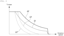
- FIG. 2 is a diagram illustrating switching of a motor driving mode according to an exemplary embodiment of the present disclosure.
- an operating point map of a motor showing an output limit curve L1 in a CEW mode, an output limit curve L2 in an OEW mode, and a mode switching reference line L3 based on an efficiency map is shown.
- the output limit curves L1 and L2 may represent output torque limit values of a motor depending on rotational speed (e.g., RPM) of the motor in respective motor driving modes.
- the output limit curve L2 has an output limit greater than that of the output limit curve L1 in at least some of the RPM range, and the output limit curves L1 and L2 may be configured in consideration of durability, heat generation, and current controllability of the motor and inverter.
- the mode switching reference line L3 based on an efficiency map may correspond to a boundary line between a high efficiency region in the CEW mode and a high efficiency region in the OEW mode.
- the efficiency map may include information about a mode with higher efficiency among the CEW mode and the OEW mode in the respective combinations of torque and reverse magnetic flux of the motor, and may have a table form depending on the implementation thereof.
- the efficiency map may be derived based on results of measuring, through a test, the loss of the motor depending on the rotational speed and torque of the motor in each motor driving mode for each DC terminal voltage of the inverter.
- the reverse magnetic flux of the motor may be inversely proportional to the DC terminal voltage of the inverter (that is, the voltage of a battery) and proportional to the speed of the motor.
- the mode switching reference line L3 may have a shape such as L3' according to the specifications of a motor driving device.
- the mode switching reference lines L3 and L3' are shown in FIG. 2 by way of example and are not necessarily limited thereto.
- the controller 70 may bilaterally switch the CEW mode and the OEW mode depending on a torque command value of the motor and a reverse magnetic flux value thereof with reference to the efficiency map.
- the reverse magnetic flux value may be calculated based on a torque command for the motor, a DC terminal voltage of the inverter, and a required speed of the motor.
- the controller 70 may correct the mode switching reference line in consideration of output limit, hysteresis or the like for the motor driving mode and, in this case, switch the motor driving mode depending on the torque command value for the motor and the reverse magnetic flux value thereof based on the corrected mode switching reference line.
- FIG. 3 A structure for this is shown in FIG. 3 .
- FIG. 3 is a circuit diagram of a motor driving device included in an electrified vehicle according to an exemplary embodiment of the present disclosure.
- a motor driving device may include a main battery 50, an auxiliary battery 51, a DC capacitor 60, a controller 70, a motor system 100, charging switches T1 and T2, a DC capacitor Cn, main relays MRLY1 and MRLY2, sub-relays SRLY1 and SRLY2, and a pre-charging circuit PRE-C.
- the motor system 100 may be electrically connected to the main battery 50 and may include dual inverters 10 and 20, a motor 30, a mode switching unit 40, and a diode d1.
- the diode d1 may have an anode connected to an internal node N and a cathode connected to the positive (+) DC terminal of the second inverter 20.
- the main relay MRLY1 may be connected between the positive (+) pole of the main battery 50 and the positive (+) DC terminal of the first inverter 10, and the main relay MRLY2 may be connected between the negative (-) pole of the main battery 50 and the negative (-) DC terminal of the first inverter 10.
- the DC capacitor 60 may be connected between the positive (+) DC terminal and the negative (-) DC terminal of the first inverter 10 in order to reduce the ripple with respect to the current of the main battery 50.
- the sub-relay SRLY1 may be connected between the positive (+) pole of the auxiliary battery 51 and the internal node N, and the sub-relay SRLY2 may be connected between the negative (-) pole of the auxiliary battery 51 and the negative (-) DC terminal of the second inverter 20.
- the DC capacitor Cn may be connected between the positive (+) pole and the negative (-) pole of the auxiliary battery 51 in order to reduce the ripple with respect to the current of the auxiliary battery 51.
- the pre-charging circuit PRE-C may be connected to the positive (+) pole of the auxiliary battery 51 and may be connected in parallel to the sub-relay SRLY1. Although the pre-charging circuit PRE-C may be implemented as a circuit in which a resistor and a relay are connected in parallel, it is not necessarily limited thereto.
- the charging switches T1 and T2 may be connected in series between the internal node N of the motor system 100 and the positive (+) pole of the auxiliary battery 51. More specifically, a collector terminal of the charging switch T1 may be connected to the internal node N, and a collector terminal of the charging switch T2 may be connected to the positive (+) pole of the auxiliary battery 51 through the sub-relay SRLY1, and an emitter end of each of the charging switches T1 and T2 may be interconnected to form a common node.
- the charging switches T1 and T2 are implemented as insulated gate bipolar transistors (IGBTs), they may also be implemented as MOSFETs according to various exemplary embodiments of the present disclosure.
- controller 70 controls execution of a motor driving mode including a CEW mode and an OEW mode, and a charging mode during driving will be described.
- the controller 70 may turn on the transfer switches S31, S32, and S33 such that a neutral point of the motor 30 is formed at the internal node N, turn off the charging switches T1 and T2 so as to cut off the boost charging path connected from the auxiliary battery 51 to the main battery 50 through the motor system 100, and perform control such that the motor 30 is to be driven through the first inverter 10 among the first and second inverters 10 and 20.
- the controller 70 may turn off the transfer switches S31, S32, and S33 such that a neutral point of the motor 30 is not formed at the internal node N, turn off the charging switches T1 and T2 such that the boost charging path is cut off, and perform control such that the motor 30 is to be driven through the first and second inverters 10 and 20.
- the controller 70 when the CEW mode or OEW mode is performed, may perform space vector pulse width modulation (SVPWM) control without a DC offset for each of the phase currents Iu, Iv, and Iw of the motor 30.
- the controller 70 may set the zero-phase current command value for the DC offset to "0".
- the SVPWM control may refer to a method of synthesizing a reference voltage vector with a zero-voltage vector using two effective voltage vectors adjacent to the reference voltage vector in a complex space.
- the controller 70 may switch the CEW mode to the charging mode while driving based on a predetermined command for performing the charging mode.
- the controller 70 may turn on the transfer switches S31, S32, and S33 such that a neutral point of the motor 30 is formed at the internal node N, turn on the charging switches T1 and T2 such that a boost charging path is formed to be connected from the auxiliary battery 51 to the main battery 50 through the motor system 100, and perform control such that the motor 30 is to be driven through the first inverter 10 among the first and second inverters 10 and 20.
- the controller 70 may apply a DC offset to each of the phase currents Iu, Iv, and Iw of the motor 30 having a plurality of phases based on a charging current command for the auxiliary battery 51. More specifically, when the charging mode while driving is performed, the controller 70 may divide a charging current command value by the number of phases (e.g., 3) to generate a zero-phase current command for the DC offset, and output multiple switching signals for pulse width modulation control based on the zero-phase current command.
- the number of phases e.g., 3
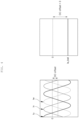
- phase currents Iu, Iv, and Iw of the motor 30 and charging current Ia_bat of the auxiliary battery 51 when the charging mode is performed during driving is illustrated.
- the respective phase currents Iu, Iv, and Iw of the motor 30 may have DC offsets and may have a phase difference of 120 degrees between each other. Since the charging current Ia_bat is equal to the sum of the phase currents Iu, Iv, and Iw of the motor 30, it may have a DC waveform obtained by multiplying the DC offset by the number of phases (e.g., 3).
- the charging current Ia_bat may be output from the auxiliary battery 51 to the main battery 50 so that the motor system 100 may transfer the power of the auxiliary battery 51 to the main battery 50.
- the controller 70 applies a positive (+) DC offset to each of the phase currents Iu, Iv, and Iw of the motor 30, the charging current Ia_bat may be output from the main battery 50 to the auxiliary battery 51 so that the motor system 100 may transfer the power of the main battery 50 to the auxiliary battery 51.
- the controller 70 when the charging mode while driving is performed, may output a plurality of switching signals Su, Sv, and Sw to perform preconfigured pulse width modulation control for the first inverter 10 such that the motor system 100 boosts the voltage of the auxiliary battery 51 to charge the main battery 50, and control the DC offset for each of the phase currents Iu, Iv, and Iw of the motor 30.
- the plurality of switching signals Su, Sv, and Sw may correspond to the first leg 11, the second leg 12, and the third leg 13, respectively.
- the preconfigured pulse width modulation control may be configured as one of either space vector pulse width modulation (SVPWM) control or remote state pulse width modulation (RSPWM) control.
- the RSPWM control may refer to a method of synthesizing a reference voltage vector using three effective voltage vectors having a phase difference of 120 degrees from each other in a complex space.
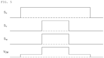
- FIG. 5 an example of waveforms of a plurality of switching signals Su, Sv, and Sw and a common mode voltage V CM when the controller 70 performs SVPWM control is illustrated.
- the respective switching signals Su, Sv, and Sw may have center-aligned waveforms within one duty cycle.
- the maximum amplitude of the common mode voltage V CM may correspond to the voltage of the main battery 50 when the SVPWM control is performed.
- the common mode voltage V CM may correspond to a potential difference between the ground terminal and the neutral point of the motor 30.
- FIG. 6 an example of waveforms of a plurality of switching signals Su, Sv, and Sw and a common mode voltage V CM when the controller 70 performs RSPWM control is illustrated.
- the maximum amplitude of the common mode voltage V CM may correspond to a value obtained by dividing the voltage of the main battery 50 by 3 when the RSPWM control is performed. That is, since the RSPWM control method in FIG. 6 generates less pulsation of the common mode voltage V CM than the SVPWM control method in FIG. 5 , the controller 70 may reduce a current ripple generated at the neutral point of the motor 30 through the RSPWM control in the charging mode while driving.
- the controller 70 may pre-charge the DC capacitor Cn connected between the positive (+) pole and the negative (-) pole of the auxiliary battery 51 through the pre-charging circuit PRE-C connected to the auxiliary battery 51. After pre-charging the DC capacitor Cn, the controller 70 may switch each of the plurality of legs 11, 12, and 13 so as to configure the neutral point voltage (i.e., common mode voltage) of the motor 30 as the voltage of the auxiliary battery 51. At this time, the controller 70 may switch the pulse width modulation control method from the SVPWM control method to a preconfigured pulse width modulation control (e.g., RSPWM) method.
- a preconfigured pulse width modulation control e.g., RSPWM
- the controller 70 may turn on the charging switches T1 and T2 in a turn-off state and may apply a DC offset to each of the phase currents Iu, Iv, and Iw of the motor 30 according to a charging current command value for the auxiliary battery 51.
- the controller 70 may configure the zero-phase current command value for the DC offset as "0" and then switch each of the plurality of legs 11, 12, and 13, thereby maintaining the neutral point voltage of the motor 30. At this time, the controller 70 may turn off the charging switches T1 and T2 in the turn-on state. When the charging switches T1 and T2 are turned off, the controller 70 may switch each of the plurality of legs 11, 12, and 13 through SVPWM control.
- FIG. 7 is a circuit diagram illustrating the configuration of a motor driving system included in an electrified vehicle according to another exemplary embodiment of the present disclosure.
- a charging switch T1 and a charging switch T2 may be connected in parallel between an internal node N and the positive (+) pole of an auxiliary battery 51. More specifically, the collector terminal of the charging switch T1 and the emitter terminal of the charging switch T2 may be connected to the internal node N, and the emitter terminal of the charging switch T1 and the collector terminal of the charging switch T2 may be connected to the positive (+) pole of the auxiliary battery 51 through the sub-relay SRLY1.
- the charging switches T1 and T2 when the charging switches T1 and T2 are turned on, only one of the charging switches T1 and T2 is in a conduction state depending on the current direction of the internal node N, so the conduction loss of the charging switches T1 and T2 may be minimized.
- the charging switches T1 and T2 may be implemented as transistors (e.g., IGBTs) having no reverse conduction characteristics.
- FIG. 8 is a flowchart illustrating a control method of an electrified vehicle according to an exemplary embodiment of the present disclosure.
- the controller 70 may determine whether or not a CEW mode is performed (S101).
- the controller 70 may perform control such that the motor system 100 operates the motor 30 through the first and second inverters 10 and 20 based on the voltage of the main battery 50 (S102). At this time, the controller 70 may turn off the transfer switches S31, S32, and S33 such that a neutral point of the motor 30 is not formed at the internal node N and turn off the charging switches T1 and T2 so as to cut off the boost charging path connected from the auxiliary battery 51 to the main battery 50 through the motor system 100.
- the controller 70 may control the motor system 100 to drive the motor 30 through the first inverter 10 among the first and second inverters 10 and 20 based on the voltage of the main battery 50 (S103). At this time, the controller 70 may turn on the transfer switches S31, S32, and S33 such that a neutral point of the motor 30 is formed at the internal node N and turn off the charging switches T1 and T2 so as to cut off the boost charging path.
- a zero-phase current command for the DC offset may be configured as "0".
- the controller 70 may determine whether or not a charging mode while driving is performed (S104). When the charging mode while driving is not performed ("NO" in S104), S101 may be re-performed.
- the controller 70 may sequentially perform S105, S106, and S107 to switch the CEW mode to the charging mode while driving. More specifically, the controller 70 may pre-charge the DC capacitor Cn connected between the positive (+) pole and the negative (-) pole of the auxiliary battery 51 through the pre-charging circuit PRE-C connected to the auxiliary battery 51 (S105). After pre-charging the DC capacitor Cn, the controller 70 may switch each of the plurality of legs 11, 12, and 13 to configure the neutral point voltage of the motor 30 as the voltage of the auxiliary battery 51 (S106). Thereafter, the controller 70 may turn on the charging switches T1 and T2 so as to form a boost charging path connected from the auxiliary battery 51 to the main battery 50 through the motor system 100 (S107).
- the controller 70 may perform preconfigured pulse width modulation control for the first inverter 10 to control a DC offset for each phase current of the motor 30 having a plurality of phases (S108). More specifically, the controller 70 may divide a charging current command value for the auxiliary battery 51 by the number of phases to generate a zero-phase current command for the DC offset, and perform preconfigured pulse width modulation control (e.g., SVPWM control or RSPWM control) based on the zero-phase current command, thereby switching each of the plurality of legs 11, 12, and 13. Accordingly, the motor system 100 may charge the main battery 50 by discharging the auxiliary battery 51 when the DC offset is negative (-), and charge the auxiliary battery 51 by discharging the main battery 50 when the DC offset is positive (+).
- preconfigured pulse width modulation control e.g., SVPWM control or RSPWM control
- the controller 70 may determine whether or not the charging mode while driving is terminated (S109). When the charging mode while driving is not terminated ("NO" in S109), S108 may be re-performed.
- the controller 70 may sequentially perform S110, Sill, and S112, thereby switching the charging mode while driving to the CEW mode. More specifically, the controller 70 may configure the zero-phase current command value for the DC offset as "0" (S110). Thereafter, the controller 70 may switch each of the plurality of legs 11, 12, and 13 to maintain the neutral point voltage of the motor 30 (Sill), and turned off the charging switches T1 and T2 to cut off the boost charging path connected from the auxiliary battery 51 to the main battery 50 through the motor system 100 (S112). Thereafter, S103 may be performed again.
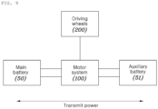
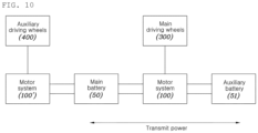
- FIGS. 9 and 10 are block diagrams illustrating an example of a motor driving system to which the present disclosure is applied.
- the motor system 100 may transmit power to driving wheels 200 (e.g., rear wheels) provided in a two-wheel drive electrified vehicle based on the voltage of the main battery 50 in a motor driving mode.
- the motor system 100 may control power transmission between the main battery 50 and the auxiliary battery 51 while transmitting power to the driving wheels 200 in a charging mode while driving.
- the motor system 100 may be applied to a four-wheel drive electrified vehicle having main driving wheels 300 (e.g., rear wheels) and auxiliary driving wheels 400 (e.g., front wheels).
- the four-wheel drive electrified vehicle based on the voltage of the main battery 50, may always transmit power to the main driving wheels 300 through the motor system 100 while driving and selectively transmit power to the auxiliary driving wheels 400 through a motor system 100' depending on whether or not four-wheel driving is executed while driving.
- the motor system 100 may control power transmission between the main battery 50 and the auxiliary battery 51 while transmitting power to the main driving wheels 300 in the charging mode while driving.
Landscapes
- Engineering & Computer Science (AREA)
- Power Engineering (AREA)
- Transportation (AREA)
- Mechanical Engineering (AREA)
- Life Sciences & Earth Sciences (AREA)
- Sustainable Development (AREA)
- Sustainable Energy (AREA)
- Electric Propulsion And Braking For Vehicles (AREA)
Abstract
Description
- The present disclosure relates to an electrified vehicle that controls charging and discharging of a battery while driving and a method of controlling the same.
- In line with the recent global trend of reducing carbon dioxide emissions, there is an increasing demand for electrified vehicles that generate driving power by driving a motor with electric energy stored in a battery, instead of typical internal combustion engine vehicles that generate driving power by burning fossil fuels.
- In general, a coil in each phase included in a motor of an electrified vehicle has one end connected to one inverter and an opposite end connected thereto, thereby forming a Y-connection.
- When the motor is driven, a switching element in the inverter is turned on/off by pulse width modulation control and applies a line-to-line voltage to the coil of the motor forming the Y-connection in order to generate an alternating current, thereby generating a torque.
- The fuel efficiency (or electric efficiency) of an eco-friendly vehicle such as an electric vehicle that uses the torque generated by the above motor as power is determined by the power conversion efficiency of the inverter-motor, so it is important to maximize the power conversion efficiency of the inverter and the efficiency of the motor.
- The efficiency of the inverter-motor system is mainly determined by a voltage utilization rate of the inverter. Therefore, when the driving point of the vehicle determined by the relationship between motor speed and torque is formed in the section having a high voltage utilization rate, the fuel efficiency of the vehicle may be improved.
- However, as the number of coils of the motor increases to raise the maximum torque of the motor, the section with a high voltage utilization rate becomes farther away from a low torque region, which is the main driving point of the vehicle, so that the fuel efficiency of the vehicle may deteriorate. In addition, in terms of fuel efficiency, when the main driving point is designed to be included in the section having a high voltage utilization rate, the maximum torque of the motor may be limited, which may cause a problem in which the acceleration performance of the vehicle is lowered.
- In this field of technology, since there is a demand for motor driving technology capable of improving system efficiency while covering both low and high power sections by one motor, a technology of driving one motor in two different modes using two inverters and a mode transfer switch has been recently introduced.
- The information disclosed in the background section above is to aid in the understanding of the background of the present disclosure and should not be regarded as acknowledgement that this information forms any part of prior art.
- Various aspects of the present disclosure are directed to an electrified vehicle that can efficiently improve the mileage of the electrified vehicle by charging a main battery by boosting the voltage of an auxiliary battery through a motor system while driving.
- The technical subjects pursued in the present disclosure may not be limited to the above-mentioned technical subjects, and other technical subjects which are not mentioned may be clearly understood, through the following descriptions, by those skilled in the art to which the present disclosure pertains.
- As an exemplary embodiment of the present disclosure, an electrified vehicle may include: a main battery and an auxiliary battery; a motor system including a dual inverter connected to the main battery and driving a motor depending on a motor driving mode, and a transfer switch for switching between first and second driving modes included in the motor driving mode; and a charging switch connected between the motor system and the auxiliary battery, and configured to form a boost charging path connected from the auxiliary battery to the main battery through the motor system when the first driving mode switches to a charging mode while driving.
- In addition, as another exemplary embodiment of the present disclosure, an electrified vehicle may include: a main battery and an auxiliary battery; a motor system configured to drive a motor through an inverter connected to the main battery; and a controller configured to perform, when a charging mode while driving is performed, a preconfigured pulse width modulation control on the inverter to control a DC offset for a phase current of the motor such that the motor system boosts the voltage of the auxiliary battery to charge the main battery.
- In addition, as still another exemplary embodiment of the present disclosure, a method of controlling an electrified vehicle may include: driving a motor through an inverter based on a voltage of a main battery in a motor system; and forming a boost charging path connected from an auxiliary battery to the main battery through the motor system when a charging mode while driving is performed in a state in which the motor is driven.
- According to various exemplary embodiments of the present disclosure, it is possible to efficiently improve the mileage of an electrified vehicle by charging a main battery by boosting the voltage of an auxiliary battery through a motor system while driving.
- Advantageous effects obtainable from the present disclosure may not be limited to the above-mentioned effects, and other effects which are not mentioned may be clearly understood, through the following descriptions, by those skilled in the art to which the present disclosure pertains.
- The above and other aspects, features, and advantages of the present disclosure will be more apparent from the following detailed description taken in conjunction with the accompanying drawings, in which:
-
FIG. 1 is a circuit diagram illustrating an example of a motor driving device according to an exemplary embodiment of the present disclosure; -
FIG. 2 is a diagram illustrating switching of a motor driving mode according to an exemplary embodiment of the present disclosure; -
FIG. 3 is a circuit diagram of a motor driving device included in an electrified vehicle according to an exemplary embodiment of the present disclosure; -
FIG. 4 is a waveform diagram of phase current of a motor and current of an auxiliary battery when a charging mode while driving is performed according to an exemplary embodiment of the present disclosure; -
FIGS. 5 and6 are waveform diagrams illustrating an operation in which a controller controls a switching state of an inverter in a charging mode while driving according to an exemplary embodiment of the present disclosure; -
FIG. 7 is a circuit diagram of a motor driving device included in an electrified vehicle according to another exemplary embodiment of the present disclosure; -
FIG. 8 is a flowchart illustrating a control method of an electrified vehicle according to an exemplary embodiment of the present disclosure; and -
FIGS. 9 and10 are block diagrams illustrating an example of a motor driving system to which the present disclosure is applied. - Reference will now be made in detail to various embodiments of the present disclosure(s), examples of which are illustrated in the accompanying drawings and described below. While the present disclosure(s) will be described in conjunction with exemplary embodiments of the present disclosure, it will be understood that the present description is not intended to limit the present disclosure(s) to those exemplary embodiments of the present disclosure. On the other hand, the present disclosure(s) is/are intended to cover not only the exemplary embodiments of the present disclosure, but also various alternatives, modifications, equivalents and other embodiments, which may be included within the spirit and scope of the present disclosure as defined by the appended claims.
- Hereinafter, embodiments disclosed in the present specification will be described in detail with reference to the accompanying drawings, and the same or similar elements are given the same and similar reference numerals, so duplicate descriptions thereof will be omitted. The terms "module" and "unit" used for the elements in the following description are given or interchangeably used in consideration of only the ease of writing the specification, and do not have distinct meanings or roles by themselves. In describing the embodiments disclosed in the present specification, when the detailed description of the relevant known technology is determined to unnecessarily obscure the gist of the present disclosure, the detailed description may be omitted. Furthermore, the accompanying drawings are provided only for easy understanding of the embodiments disclosed in the present specification, and the technical spirit disclosed herein is not limited to the accompanying drawings, and it should be understood that all changes, equivalents, or substitutes thereof are included in the spirit and scope of the present disclosure.
- Terms including an ordinal number such as "first", "second", or the like may be used to describe various elements, but the elements are not limited to the terms. The above terms are used only for the purpose of distinguishing one element from another element.
- In the case where an element is referred to as being "connected" or "coupled" to any other element, it should be understood that another element may be provided therebetween, as well as that the element may be directly connected or coupled to the other element. In contrast, in the case where an element is "directly connected" or "directly coupled" to any other element, it should be understood that no other element is present therebetween.
- A singular expression may include a plural expression unless they are definitely different in a context.
- As used herein, the expression "include" or "have" are intended to specify the existence of mentioned features, numbers, steps, operations, elements, components, or combinations thereof, and should be construed as not precluding the possible existence or addition of one or more other features, numbers, steps, operations, elements, components, or combinations thereof.
- A unit or a control unit included in names such as a motor control unit (MCU) is merely a term widely used for naming a controller configured to control a specific function of a vehicle, but does not mean a generic function unit. For example, each controller may include a communication device configured to communicate with a sensor or another control unit, a non-transitory memory configured to store an operation system, a logic command, or input/output information, and at least one processor configured to perform determination, calculation, decision or the like which are required for responsible function controlling.
-
FIG. 1 is a circuit diagram illustrating an example of a motor driving device according to an exemplary embodiment of the present disclosure. - Referring to
FIG. 1 , a motor driving device according to an exemplary embodiment of the present disclosure may include amain battery 50, a DC capacitor (or DC-Link capacitor) 60, acontroller 70, and amotor system 100. - The
motor system 100 may includedual inverters motor 30 having a plurality of coils C1, C2, and C3 respectively corresponding to a plurality of phases, and amode switching unit 40. - The
first inverter 10 may include a plurality of first switching elements S11, S12, S13, S14, S15 and S16 connected to one ends of the plurality of coils C1, C2, and C3, and thesecond inverter 20 may include a plurality of second switching elements S21, S22, S23, S24, S25 and S26 connected to the opposite ends of the plurality of coils C1, C2, and C3. Themode switching unit 40 may include a plurality of transfer switches S31, S32, and S33. Thecontroller 70 may control on/off states of the plurality of first switching elements S11 to S16, the plurality of second switching elements S21 to S26, and the transfer switches S31, S32, and S33 based on an output required for the motor 30 (i.e., torque command for the motor 30), DC terminal voltages of theinverters 10 and 20 (i.e., the voltage of the main battery 50), the phase current of themotor 30, and the motor angle. - The
first inverter 10 may include a plurality oflegs DC capacitor 60 connected between both ends of themain battery 50 is applied. Thelegs motor 30 to form electrical connections. More specifically, thefirst leg 11 may include two switching elements S11 and S12 connected in series to each other between both ends of theDC capacitor 60, and a connection node of the two switching elements S11 and S12 may be connected to one end of the coil C1 in one phase in themotor 30 such that AC power corresponding to one of the plurality of phases is input and output therethrough. Similarly, thesecond leg 12 may include two switching elements S13 and S14 connected in series to each other between both ends of theDC capacitor 60, and a connection node of the two switching elements S13 and S14 may be connected to one end of the coil C2 in one phase in themotor 30 such that AC power corresponding to one of the plurality of phases is input and output therethrough. In addition, thethird leg 13 may include two switching elements S15 and S16 connected in series to each other between both ends of theDC capacitor 60, and a connection node of the two switching elements S15 and S16 may be connected to one end of the coil C3 in one phase in themotor 30 such that AC power corresponding to one of the plurality of phases is input and output therethrough. - The
second inverter 20 may include a plurality oflegs DC capacitor 60 connected between both ends of themain battery 50 is applied. Thelegs motor 30 to form electrical connections. More specifically, thefirst leg 21 may include two switching elements S21 and S22 connected in series to each other between both ends of theDC capacitor 60, and a connection node of the two switching elements S21 and S22 may be connected to the opposite end of the coil C1 in one phase in themotor 30 such that AC power corresponding to one of the plurality of phases is input and output therethrough. Similarly, thesecond leg 22 may include two switching elements S23 and S24 connected in series to each other between both ends of theDC capacitor 60, and a connection node of the two switching elements S23 and S24 may be connected to the opposite end of the coil C2 in one phase in themotor 30 such that AC power corresponding to one of the plurality of phases is input and output therethrough. In addition, thethird leg 23 may include two switching elements S25 and S26 connected in series to each other between both ends of theDC capacitor 60, and a connection node of the two switching elements S25 and S26 may be connected to the opposite end of the coil C3 in one phase in themotor 30 such that AC power corresponding to one of the plurality of phases is input and output therethrough. - One ends of the plurality of transfer switches S31, S32, and S33 may be respectively connected to different opposite ends of the plurality of coils C1, C2, and C3, and the opposite ends thereof may be interconnected at an internal node N. The plurality of transfer switches S31, S32, and S33 may employ various switching means, such as MOSFET, IGBT, thyristors, relays, or the like.
- Although not shown in
FIG. 1 , the motor driving device may further include a so-called Y-capacitor (Y-Cap) in which two capacitors connected in series to each other are connected between a positive (+) DC terminal and a negative (-) DC terminal and a connection node between the capacitors is grounded. - The
controller 70 may perform pulse width modulation control for switching the first switching elements S11 to S16 and the second switching elements S21 to S26 based on an output required by themotor 30, thereby driving themotor 30. Thecontroller 70 may switch thedual inverters motor 30, and control on/off states of the transfer switches S31, S32, and S33 for switching between a CEW mode and an OEW mode included in the motor driving mode. In this case, a first driving mode may be referred to as a "closed end winding (CEW) mode", and a second driving mode may be referred to as an "open end winding (OEW) mode". More specifically, when the CEW mode is performed, thecontroller 70 may turn on the transfer switches S31, S32, and S33 such that a neutral point of themotor 30 is formed at the internal node N, and control driving of themotor 30 through thefirst inverter 10 among the first andsecond inverters controller 70 may turn off the transfer switches S31, S32, and S33 such that a neutral point of themotor 30 is not formed at the internal node N, and control driving of themotor 30 through the first andsecond inverters -
FIG. 2 is a diagram illustrating switching of a motor driving mode according to an exemplary embodiment of the present disclosure. - Referring to
FIG. 2 , an operating point map of a motor showing an output limit curve L1 in a CEW mode, an output limit curve L2 in an OEW mode, and a mode switching reference line L3 based on an efficiency map is shown. - The output limit curves L1 and L2 may represent output torque limit values of a motor depending on rotational speed (e.g., RPM) of the motor in respective motor driving modes. The output limit curve L2 has an output limit greater than that of the output limit curve L1 in at least some of the RPM range, and the output limit curves L1 and L2 may be configured in consideration of durability, heat generation, and current controllability of the motor and inverter.
- The mode switching reference line L3 based on an efficiency map (not shown) may correspond to a boundary line between a high efficiency region in the CEW mode and a high efficiency region in the OEW mode. The efficiency map may include information about a mode with higher efficiency among the CEW mode and the OEW mode in the respective combinations of torque and reverse magnetic flux of the motor, and may have a table form depending on the implementation thereof. For example, the efficiency map may be derived based on results of measuring, through a test, the loss of the motor depending on the rotational speed and torque of the motor in each motor driving mode for each DC terminal voltage of the inverter. In this case, the reverse magnetic flux of the motor may be inversely proportional to the DC terminal voltage of the inverter (that is, the voltage of a battery) and proportional to the speed of the motor.
- According to an exemplary embodiment, the mode switching reference line L3 may have a shape such as L3' according to the specifications of a motor driving device. However, the mode switching reference lines L3 and L3' are shown in
FIG. 2 by way of example and are not necessarily limited thereto. - In order to switch the motor driving mode according to the mode switching reference line L3, the
controller 70 may bilaterally switch the CEW mode and the OEW mode depending on a torque command value of the motor and a reverse magnetic flux value thereof with reference to the efficiency map. In this case, the reverse magnetic flux value may be calculated based on a torque command for the motor, a DC terminal voltage of the inverter, and a required speed of the motor. According to an exemplary embodiment, thecontroller 70 may correct the mode switching reference line in consideration of output limit, hysteresis or the like for the motor driving mode and, in this case, switch the motor driving mode depending on the torque command value for the motor and the reverse magnetic flux value thereof based on the corrected mode switching reference line. - Hereinafter, a description will be made to an electrified vehicle that forms a boost charging path connected from an auxiliary battery to a main battery through a motor system when a charging mode while driving is performed to boost the voltage of the auxiliary battery while driving, thereby controlling the charging of the main battery. A structure for this is shown in
FIG. 3 . -
FIG. 3 is a circuit diagram of a motor driving device included in an electrified vehicle according to an exemplary embodiment of the present disclosure. - Referring to
FIG. 3 , a motor driving device according to an exemplary embodiment of the present disclosure may include amain battery 50, anauxiliary battery 51, aDC capacitor 60, acontroller 70, amotor system 100, charging switches T1 and T2, a DC capacitor Cn, main relays MRLY1 and MRLY2, sub-relays SRLY1 and SRLY2, and a pre-charging circuit PRE-C. - The
motor system 100 may be electrically connected to themain battery 50 and may includedual inverters motor 30, amode switching unit 40, and a diode d1. In this case, the diode d1 may have an anode connected to an internal node N and a cathode connected to the positive (+) DC terminal of thesecond inverter 20. - The main relay MRLY1 may be connected between the positive (+) pole of the
main battery 50 and the positive (+) DC terminal of thefirst inverter 10, and the main relay MRLY2 may be connected between the negative (-) pole of themain battery 50 and the negative (-) DC terminal of thefirst inverter 10. TheDC capacitor 60 may be connected between the positive (+) DC terminal and the negative (-) DC terminal of thefirst inverter 10 in order to reduce the ripple with respect to the current of themain battery 50. - The sub-relay SRLY1 may be connected between the positive (+) pole of the
auxiliary battery 51 and the internal node N, and the sub-relay SRLY2 may be connected between the negative (-) pole of theauxiliary battery 51 and the negative (-) DC terminal of thesecond inverter 20. The DC capacitor Cn may be connected between the positive (+) pole and the negative (-) pole of theauxiliary battery 51 in order to reduce the ripple with respect to the current of theauxiliary battery 51. The pre-charging circuit PRE-C may be connected to the positive (+) pole of theauxiliary battery 51 and may be connected in parallel to the sub-relay SRLY1. Although the pre-charging circuit PRE-C may be implemented as a circuit in which a resistor and a relay are connected in parallel, it is not necessarily limited thereto. - The charging switches T1 and T2 may be connected in series between the internal node N of the
motor system 100 and the positive (+) pole of theauxiliary battery 51. More specifically, a collector terminal of the charging switch T1 may be connected to the internal node N, and a collector terminal of the charging switch T2 may be connected to the positive (+) pole of theauxiliary battery 51 through the sub-relay SRLY1, and an emitter end of each of the charging switches T1 and T2 may be interconnected to form a common node. In this embodiment, although the charging switches T1 and T2 are implemented as insulated gate bipolar transistors (IGBTs), they may also be implemented as MOSFETs according to various exemplary embodiments of the present disclosure. - Hereinafter, an operation method in which the
controller 70 controls execution of a motor driving mode including a CEW mode and an OEW mode, and a charging mode during driving will be described. - When the CEW mode is performed, the
controller 70 may turn on the transfer switches S31, S32, and S33 such that a neutral point of themotor 30 is formed at the internal node N, turn off the charging switches T1 and T2 so as to cut off the boost charging path connected from theauxiliary battery 51 to themain battery 50 through themotor system 100, and perform control such that themotor 30 is to be driven through thefirst inverter 10 among the first andsecond inverters controller 70 may turn off the transfer switches S31, S32, and S33 such that a neutral point of themotor 30 is not formed at the internal node N, turn off the charging switches T1 and T2 such that the boost charging path is cut off, and perform control such that themotor 30 is to be driven through the first andsecond inverters controller 70, when the CEW mode or OEW mode is performed, may perform space vector pulse width modulation (SVPWM) control without a DC offset for each of the phase currents Iu, Iv, and Iw of themotor 30. Thecontroller 70 may set the zero-phase current command value for the DC offset to "0". Here, the SVPWM control may refer to a method of synthesizing a reference voltage vector with a zero-voltage vector using two effective voltage vectors adjacent to the reference voltage vector in a complex space. - The
controller 70 may switch the CEW mode to the charging mode while driving based on a predetermined command for performing the charging mode. When the charging mode while driving is performed, thecontroller 70 may turn on the transfer switches S31, S32, and S33 such that a neutral point of themotor 30 is formed at the internal node N, turn on the charging switches T1 and T2 such that a boost charging path is formed to be connected from theauxiliary battery 51 to themain battery 50 through themotor system 100, and perform control such that themotor 30 is to be driven through thefirst inverter 10 among the first andsecond inverters controller 70 may apply a DC offset to each of the phase currents Iu, Iv, and Iw of themotor 30 having a plurality of phases based on a charging current command for theauxiliary battery 51. More specifically, when the charging mode while driving is performed, thecontroller 70 may divide a charging current command value by the number of phases (e.g., 3) to generate a zero-phase current command for the DC offset, and output multiple switching signals for pulse width modulation control based on the zero-phase current command. - Referring to
FIG. 4 , an example of waveforms of phase currents Iu, Iv, and Iw of themotor 30 and charging current Ia_bat of theauxiliary battery 51 when the charging mode is performed during driving is illustrated. The respective phase currents Iu, Iv, and Iw of themotor 30 may have DC offsets and may have a phase difference of 120 degrees between each other. Since the charging current Ia_bat is equal to the sum of the phase currents Iu, Iv, and Iw of themotor 30, it may have a DC waveform obtained by multiplying the DC offset by the number of phases (e.g., 3). Therefore, when thecontroller 70 applies a negative (-) DC offset to each of the phase currents Iu, Iv, and Iw of themotor 30, the charging current Ia_bat may be output from theauxiliary battery 51 to themain battery 50 so that themotor system 100 may transfer the power of theauxiliary battery 51 to themain battery 50. On the other hand, when thecontroller 70 applies a positive (+) DC offset to each of the phase currents Iu, Iv, and Iw of themotor 30, the charging current Ia_bat may be output from themain battery 50 to theauxiliary battery 51 so that themotor system 100 may transfer the power of themain battery 50 to theauxiliary battery 51. - The
controller 70, when the charging mode while driving is performed, may output a plurality of switching signals Su, Sv, and Sw to perform preconfigured pulse width modulation control for thefirst inverter 10 such that themotor system 100 boosts the voltage of theauxiliary battery 51 to charge themain battery 50, and control the DC offset for each of the phase currents Iu, Iv, and Iw of themotor 30. In this case, the plurality of switching signals Su, Sv, and Sw may correspond to thefirst leg 11, thesecond leg 12, and thethird leg 13, respectively. In this embodiment, the preconfigured pulse width modulation control may be configured as one of either space vector pulse width modulation (SVPWM) control or remote state pulse width modulation (RSPWM) control. Here, the RSPWM control may refer to a method of synthesizing a reference voltage vector using three effective voltage vectors having a phase difference of 120 degrees from each other in a complex space. - Referring to
FIG. 5 , an example of waveforms of a plurality of switching signals Su, Sv, and Sw and a common mode voltage VCM when thecontroller 70 performs SVPWM control is illustrated. In this case, the respective switching signals Su, Sv, and Sw may have center-aligned waveforms within one duty cycle. The maximum amplitude of the common mode voltage VCM may correspond to the voltage of themain battery 50 when the SVPWM control is performed. Here, the common mode voltage VCM may correspond to a potential difference between the ground terminal and the neutral point of themotor 30. - Referring to
FIG. 6 , an example of waveforms of a plurality of switching signals Su, Sv, and Sw and a common mode voltage VCM when thecontroller 70 performs RSPWM control is illustrated. The maximum amplitude of the common mode voltage VCM may correspond to a value obtained by dividing the voltage of themain battery 50 by 3 when the RSPWM control is performed. That is, since the RSPWM control method inFIG. 6 generates less pulsation of the common mode voltage VCM than the SVPWM control method inFIG. 5 , thecontroller 70 may reduce a current ripple generated at the neutral point of themotor 30 through the RSPWM control in the charging mode while driving. - Hereinafter, an operation method for controlling the
motor system 100 when thecontroller 70 switches between the CEW mode and the charging mode while driving will be described with reference back toFIG. 3 . - When the CEW mode switches to the charging mode while driving, the
controller 70 may pre-charge the DC capacitor Cn connected between the positive (+) pole and the negative (-) pole of theauxiliary battery 51 through the pre-charging circuit PRE-C connected to theauxiliary battery 51. After pre-charging the DC capacitor Cn, thecontroller 70 may switch each of the plurality oflegs motor 30 as the voltage of theauxiliary battery 51. At this time, thecontroller 70 may switch the pulse width modulation control method from the SVPWM control method to a preconfigured pulse width modulation control (e.g., RSPWM) method. Thereafter, thecontroller 70 may turn on the charging switches T1 and T2 in a turn-off state and may apply a DC offset to each of the phase currents Iu, Iv, and Iw of themotor 30 according to a charging current command value for theauxiliary battery 51. - When the charging mode switches to the CEW mode while driving, the
controller 70 may configure the zero-phase current command value for the DC offset as "0" and then switch each of the plurality oflegs motor 30. At this time, thecontroller 70 may turn off the charging switches T1 and T2 in the turn-on state. When the charging switches T1 and T2 are turned off, thecontroller 70 may switch each of the plurality oflegs -
FIG. 7 is a circuit diagram illustrating the configuration of a motor driving system included in an electrified vehicle according to another exemplary embodiment of the present disclosure. - Referring to
FIG. 7 , a charging switch T1 and a charging switch T2 may be connected in parallel between an internal node N and the positive (+) pole of anauxiliary battery 51. More specifically, the collector terminal of the charging switch T1 and the emitter terminal of the charging switch T2 may be connected to the internal node N, and the emitter terminal of the charging switch T1 and the collector terminal of the charging switch T2 may be connected to the positive (+) pole of theauxiliary battery 51 through the sub-relay SRLY1. In the connection form shown inFIG. 7 , when the charging switches T1 and T2 are turned on, only one of the charging switches T1 and T2 is in a conduction state depending on the current direction of the internal node N, so the conduction loss of the charging switches T1 and T2 may be minimized. In this case, the charging switches T1 and T2 may be implemented as transistors (e.g., IGBTs) having no reverse conduction characteristics. -
FIG. 8 is a flowchart illustrating a control method of an electrified vehicle according to an exemplary embodiment of the present disclosure. - Referring to
FIG. 8 , thecontroller 70 may determine whether or not a CEW mode is performed (S101). - When the OEW mode is performed ("NO" in S101), the
controller 70 may perform control such that themotor system 100 operates themotor 30 through the first andsecond inverters controller 70 may turn off the transfer switches S31, S32, and S33 such that a neutral point of themotor 30 is not formed at the internal node N and turn off the charging switches T1 and T2 so as to cut off the boost charging path connected from theauxiliary battery 51 to themain battery 50 through themotor system 100. - When the CEW mode is performed ("YES" in S101), the
controller 70 may control themotor system 100 to drive themotor 30 through thefirst inverter 10 among the first andsecond inverters controller 70 may turn on the transfer switches S31, S32, and S33 such that a neutral point of themotor 30 is formed at the internal node N and turn off the charging switches T1 and T2 so as to cut off the boost charging path. Here, a zero-phase current command for the DC offset may be configured as "0". - Thereafter, the
controller 70 may determine whether or not a charging mode while driving is performed (S104). When the charging mode while driving is not performed ("NO" in S104), S101 may be re-performed. - When the charging mode while driving is performed in the state in which the
motor 30 is driven through the first inverter 10 ("YES" in S104), thecontroller 70 may sequentially perform S105, S106, and S107 to switch the CEW mode to the charging mode while driving. More specifically, thecontroller 70 may pre-charge the DC capacitor Cn connected between the positive (+) pole and the negative (-) pole of theauxiliary battery 51 through the pre-charging circuit PRE-C connected to the auxiliary battery 51 (S105). After pre-charging the DC capacitor Cn, thecontroller 70 may switch each of the plurality oflegs motor 30 as the voltage of the auxiliary battery 51 (S106). Thereafter, thecontroller 70 may turn on the charging switches T1 and T2 so as to form a boost charging path connected from theauxiliary battery 51 to themain battery 50 through the motor system 100 (S107). - When the charging mode while driving is performed, the
controller 70 may perform preconfigured pulse width modulation control for thefirst inverter 10 to control a DC offset for each phase current of themotor 30 having a plurality of phases (S108). More specifically, thecontroller 70 may divide a charging current command value for theauxiliary battery 51 by the number of phases to generate a zero-phase current command for the DC offset, and perform preconfigured pulse width modulation control (e.g., SVPWM control or RSPWM control) based on the zero-phase current command, thereby switching each of the plurality oflegs motor system 100 may charge themain battery 50 by discharging theauxiliary battery 51 when the DC offset is negative (-), and charge theauxiliary battery 51 by discharging themain battery 50 when the DC offset is positive (+). - Thereafter, the
controller 70 may determine whether or not the charging mode while driving is terminated (S109). When the charging mode while driving is not terminated ("NO" in S109), S108 may be re-performed. - When the charging mode while driving is terminated ("YES" in S109), the
controller 70 may sequentially perform S110, Sill, and S112, thereby switching the charging mode while driving to the CEW mode. More specifically, thecontroller 70 may configure the zero-phase current command value for the DC offset as "0" (S110). Thereafter, thecontroller 70 may switch each of the plurality oflegs auxiliary battery 51 to themain battery 50 through the motor system 100 (S112). Thereafter, S103 may be performed again. -
FIGS. 9 and10 are block diagrams illustrating an example of a motor driving system to which the present disclosure is applied. - Referring to
FIG. 9 , themotor system 100 according to the present embodiment may transmit power to driving wheels 200 (e.g., rear wheels) provided in a two-wheel drive electrified vehicle based on the voltage of themain battery 50 in a motor driving mode. At this time, themotor system 100 may control power transmission between themain battery 50 and theauxiliary battery 51 while transmitting power to the driving wheels 200 in a charging mode while driving. - Referring to
FIG. 10 , themotor system 100 according to the present embodiment may be applied to a four-wheel drive electrified vehicle having main driving wheels 300 (e.g., rear wheels) and auxiliary driving wheels 400 (e.g., front wheels). The four-wheel drive electrified vehicle, based on the voltage of themain battery 50, may always transmit power to themain driving wheels 300 through themotor system 100 while driving and selectively transmit power to theauxiliary driving wheels 400 through a motor system 100' depending on whether or not four-wheel driving is executed while driving. In this case, themotor system 100 may control power transmission between themain battery 50 and theauxiliary battery 51 while transmitting power to themain driving wheels 300 in the charging mode while driving.
Claims (15)
- An electrified vehicle comprising:a main battery and an auxiliary battery;a motor system comprising a dual inverter connected to the main battery and driving a motor depending on a motor driving mode, and a transfer switch for switching between first and second driving modes included in the motor driving mode; anda charging switch connected between the motor system and the auxiliary battery, and configured to form a boost charging path connected from the auxiliary battery to the main battery through the motor system when the first driving mode switches to a charging mode while driving.
- The electrified vehicle of claim 1, wherein the dual inverter comprises:a first inverter connected to the main battery and connected to one ends of a plurality of coils included in the motor; anda second inverter connected to the main battery and connected to the opposite ends of the plurality of coils,wherein the transfer switch has one end connected to any one of the opposite ends of the plurality of coils and another end connected to an internal node, andwherein the charging switch is connected between the internal node and one pole of the auxiliary battery.
- The electrified vehicle of claim 2, wherein, in the first driving mode, the transfer switch is turned on, the charging switch is turned off such that the boost charging path is cut off, and the motor is driven through the first inverter among the first and second inverters, and
wherein, in the second driving mode, the transfer switch is turned off, the charging switch is turned off such that the boost charging path is cut off, and the motor is driven through the first and second inverters. - The electrified vehicle of claim 2, wherein, in the charging mode while driving, the transfer switch is turned on, the charging switch is turned on such that the boost charging path is formed, and the motor is driven through the first inverter among the first and second inverters.
- The electrified vehicle of claim 4, further comprising a controller configured to perform preconfigured pulse width modulation control for the first inverter when the charging mode while driving is performed,
wherein the preconfigured pulse width modulation control is configured as any one of space vector pulse width modulation control and remote state pulse width modulation control. - The electrified vehicle of any one of the preceding claims, wherein when the charging mode while driving is performed, a DC offset is applied to a phase current of the motor.
- The electrified vehicle of any one of the preceding claims, further comprising a controller configured to pre-charge a DC capacitor connected between one pole and the other pole of the auxiliary battery through a pre-charging circuit connected to the auxiliary battery when the first driving mode switches to the charging mode while driving.
- The electrified vehicle of claim 7, wherein the controller is configured to configure a neutral point voltage of the motor as the voltage of the auxiliary battery after pre-charging the DC capacitor and turn on the charging switch in a turn-off state when the first driving mode switches to the charging mode while driving.
- The electrified vehicle of any one of the preceding claims, further comprising a controller configured to maintain a neutral point voltage of the motor and turn off the charging switch in a turn-on state when the charging mode while driving switches to the first driving mode.
- An electrified vehicle comprising:a main battery and an auxiliary battery;a motor system configured to drive a motor through an inverter connected to the main battery; anda controller configured to perform, when a charging mode while driving is performed, a preconfigured pulse width modulation control on the inverter to control a DC offset for a phase current of the motor such that the motor system boosts the voltage of the auxiliary battery to charge the main battery.
- The electrified vehicle of claim 10, wherein the preconfigured pulse width modulation control is configured as any one of space vector pulse width modulation control and remote state pulse width modulation control.
- The electrified vehicle of claim 10 or 11, wherein the inverter comprises:a first inverter connected to the main battery and connected to one ends of a plurality of coils included in the motor; anda second inverter connected to the main battery and connected to the opposite ends of the plurality of coils,wherein the motor system further comprises a plurality of transfer switches having one ends connected to the different opposite ends of the plurality of coils and the other ends connected to each other at an internal node,wherein the electrified vehicle further comprising a charging switch connected between the internal node and one pole of the auxiliary battery, and configured to form a boost charging path connected from the auxiliary battery to the main battery through the motor system when the charging mode while driving is performed.
- The electrified vehicle of claim 12, wherein the controller is configured to control turn-on states of the plurality of transfer switches depending on a motor driving mode, and
wherein the motor driving mode comprises:a first driving mode in which the plurality of transfer switches is turned on, the charging switch is turned off such that the boost charging path is cut off, and the motor is driven through the first inverter among the first and second inverters; anda second driving mode in which the plurality of transfer switch is turned off, the charging switch is turned off such that the boost charging path is cut off, and the motor is driven through the first and second inverters,wherein, in the charging mode while driving, the plurality of transfer switches is turned on, the charging switch is turned on such that the boost charging path is formed, and the motor is driven through the first inverter among the first and second inverters. - The electrified vehicle of claim 13, wherein the controller is configured to pre-charge a DC capacitor connected between one pole and the other pole of the auxiliary battery through a pre-charging circuit connected to the auxiliary battery when the first driving mode switches to the charging mode while driving,
wherein the controller is configured to configure a neutral point voltage of the motor as the voltage of the auxiliary battery after pre-charging the DC capacitor and turn on the charging switch in a turn-off state when the first driving mode switches to the charging mode while driving. - The electrified vehicle of claim 13, wherein the controller is configured to maintain a neutral point voltage of the motor and turn off the charging switch in a turn-on state when the charging mode while driving switches to the first driving mode.
Applications Claiming Priority (1)
| Application Number | Priority Date | Filing Date | Title |
|---|---|---|---|
| KR1020230079108A KR20240177863A (en) | 2023-06-20 | 2023-06-20 | Electrified vehicle and method controlling for the same |
Publications (1)
| Publication Number | Publication Date |
|---|---|
| EP4480740A1 true EP4480740A1 (en) | 2024-12-25 |
Family
ID=88874689
Family Applications (1)
| Application Number | Title | Priority Date | Filing Date |
|---|---|---|---|
| EP23210902.5A Pending EP4480740A1 (en) | 2023-06-20 | 2023-11-20 | Electrified vehicle and method of controlling same |
Country Status (4)
| Country | Link |
|---|---|
| US (1) | US12570171B2 (en) |
| EP (1) | EP4480740A1 (en) |
| KR (1) | KR20240177863A (en) |
| CN (1) | CN119160038A (en) |
Families Citing this family (3)
| Publication number | Priority date | Publication date | Assignee | Title |
|---|---|---|---|---|
| KR102948606B1 (en) * | 2021-08-11 | 2026-04-03 | 현대자동차주식회사 | Driving system of driving motor |
| KR102791035B1 (en) * | 2022-12-27 | 2025-04-02 | 현대오토에버 주식회사 | PWM control apparatus and method for 2 stage inverter |
| JP2025126014A (en) * | 2024-02-16 | 2025-08-28 | トヨタ自動車株式会社 | Dual Inverter System |
Citations (4)
| Publication number | Priority date | Publication date | Assignee | Title |
|---|---|---|---|---|
| US20090033253A1 (en) * | 2007-07-30 | 2009-02-05 | Gm Global Technology Operations, Inc. | Electric traction system for a vehicle having a dual winding ac traction motor |
| WO2018117084A1 (en) * | 2016-12-21 | 2018-06-28 | 株式会社デンソー | Electric power conversion device |
| WO2022054181A1 (en) * | 2020-09-09 | 2022-03-17 | 東芝キヤリア株式会社 | Motor drive device |
| US20230179086A1 (en) * | 2021-12-07 | 2023-06-08 | Hyundai Autoever Corp. | Apparatus for enabling an inverter to switch between modes and a method of controlling same |
Family Cites Families (8)
| Publication number | Priority date | Publication date | Assignee | Title |
|---|---|---|---|---|
| US5650707A (en) * | 1995-09-28 | 1997-07-22 | Electric Power Research Institute, Inc. | Inverter-controlled induction machine with an extended speed range |
| US7199535B2 (en) * | 2005-01-26 | 2007-04-03 | General Motors Corporation | Doubled-ended inverter drive system topology for a hybrid vehicle |
| US7154237B2 (en) * | 2005-01-26 | 2006-12-26 | General Motors Corporation | Unified power control method of double-ended inverter drive systems for hybrid vehicles |
| WO2014068900A1 (en) | 2012-10-29 | 2014-05-08 | 三洋電機株式会社 | Power supply device for vehicle |
| JP6701722B2 (en) | 2015-12-24 | 2020-05-27 | いすゞ自動車株式会社 | Hybrid vehicle and control method thereof |
| JP6515858B2 (en) | 2016-04-11 | 2019-05-22 | トヨタ自動車株式会社 | vehicle |
| KR102542948B1 (en) | 2018-04-13 | 2023-06-14 | 현대자동차주식회사 | Fast charging system and method for vehicle |
| KR20240092676A (en) | 2022-12-14 | 2024-06-24 | 현대자동차주식회사 | Electrified vehicle and method of controlling the same |
-
2023
- 2023-06-20 KR KR1020230079108A patent/KR20240177863A/en active Pending
- 2023-11-14 US US18/389,289 patent/US12570171B2/en active Active
- 2023-11-20 EP EP23210902.5A patent/EP4480740A1/en active Pending
-
2024
- 2024-01-10 CN CN202410040802.9A patent/CN119160038A/en active Pending
Patent Citations (4)
| Publication number | Priority date | Publication date | Assignee | Title |
|---|---|---|---|---|
| US20090033253A1 (en) * | 2007-07-30 | 2009-02-05 | Gm Global Technology Operations, Inc. | Electric traction system for a vehicle having a dual winding ac traction motor |
| WO2018117084A1 (en) * | 2016-12-21 | 2018-06-28 | 株式会社デンソー | Electric power conversion device |
| WO2022054181A1 (en) * | 2020-09-09 | 2022-03-17 | 東芝キヤリア株式会社 | Motor drive device |
| US20230179086A1 (en) * | 2021-12-07 | 2023-06-08 | Hyundai Autoever Corp. | Apparatus for enabling an inverter to switch between modes and a method of controlling same |
Also Published As
| Publication number | Publication date |
|---|---|
| CN119160038A (en) | 2024-12-20 |
| US12570171B2 (en) | 2026-03-10 |
| KR20240177863A (en) | 2024-12-30 |
| US20240424930A1 (en) | 2024-12-26 |
Similar Documents
| Publication | Publication Date | Title |
|---|---|---|
| EP4480740A1 (en) | Electrified vehicle and method of controlling same | |
| US20240146229A1 (en) | Motor-driving apparatus | |
| JP2023123426A (en) | Power battery charging method, motor control circuit and vehicle | |
| US7859201B2 (en) | Charge control apparatus, electrically powered vehicle and electric storage charge control method | |
| JP5556677B2 (en) | Battery charging circuit | |
| CN101682288B (en) | Electric Motor Controls, Electric Vehicles, and Hybrid Electric Vehicles | |
| KR102855915B1 (en) | Motor driving system | |
| EP3782841B1 (en) | System of increasing temperature of battery for vehicle | |
| JP2010051092A (en) | Charge system and vehicle including the same | |
| CN113285648A (en) | Drive charging integrated circuit, electric vehicle and control method and control system thereof | |
| KR20230009661A (en) | Bidirectional charging system for vehicle | |
| WO2018117084A1 (en) | Electric power conversion device | |
| CN104494457B (en) | A current source type plug-in hybrid electric vehicle energy transmission drive device and method | |
| US12479331B2 (en) | Electrified vehicle and method for controlling the same | |
| WO2024255433A1 (en) | Vehicle voltage conversion system, and vehicle voltage conversion controller and control method therefor | |
| US11876468B2 (en) | Motor driving apparatus | |
| CN118944536B (en) | Multi-working mode six-phase permanent magnet synchronous motor driving system for electric automobile | |
| Cheng et al. | The design and control of an electrified powertrain with switched reluctance machines for series Hybrid Electric Vehicle | |
| Bharathiraja et al. | A Common Ground Bridgeless Buck Boost PFC Converter With Negative DC Output Voltage Based on Board Bi Directional Charger for Electric Vehicles | |
| US20240190274A1 (en) | Electric vehicle and control method of same | |
| Wu et al. | High Frequency ZVT Converter for Variable DC-Link in Electric Vehicle Traction Drive | |
| US20250319777A1 (en) | Electric vehicle | |
| CN121848938A (en) | electrified vehicles | |
| JP7559617B2 (en) | Power Supplies | |
| JP2010183673A (en) | Vehicle driving device |
Legal Events
| Date | Code | Title | Description |
|---|---|---|---|
| PUAI | Public reference made under article 153(3) epc to a published international application that has entered the european phase |
Free format text: ORIGINAL CODE: 0009012 |
|
| STAA | Information on the status of an ep patent application or granted ep patent |
Free format text: STATUS: THE APPLICATION HAS BEEN PUBLISHED |
|
| AK | Designated contracting states |
Kind code of ref document: A1 Designated state(s): AL AT BE BG CH CY CZ DE DK EE ES FI FR GB GR HR HU IE IS IT LI LT LU LV MC ME MK MT NL NO PL PT RO RS SE SI SK SM TR |
|
| STAA | Information on the status of an ep patent application or granted ep patent |
Free format text: STATUS: REQUEST FOR EXAMINATION WAS MADE |
|
| P01 | Opt-out of the competence of the unified patent court (upc) registered |
Free format text: CASE NUMBER: APP_17645/2025 Effective date: 20250410 |
|
| 17P | Request for examination filed |
Effective date: 20250423 |