EP4480680A1 - Kantenanlegemaschine zum aufbringen eines kantenbandes auf ein profil einer tür/eines türpfostens - Google Patents
Kantenanlegemaschine zum aufbringen eines kantenbandes auf ein profil einer tür/eines türpfostens Download PDFInfo
- Publication number
- EP4480680A1 EP4480680A1 EP24183598.2A EP24183598A EP4480680A1 EP 4480680 A1 EP4480680 A1 EP 4480680A1 EP 24183598 A EP24183598 A EP 24183598A EP 4480680 A1 EP4480680 A1 EP 4480680A1
- Authority
- EP
- European Patent Office
- Prior art keywords
- pressing device
- axis
- edging
- moving
- edging machine
- Prior art date
- Legal status (The legal status is an assumption and is not a legal conclusion. Google has not performed a legal analysis and makes no representation as to the accuracy of the status listed.)
- Pending
Links
Images






Classifications
-
- B—PERFORMING OPERATIONS; TRANSPORTING
- B29—WORKING OF PLASTICS; WORKING OF SUBSTANCES IN A PLASTIC STATE IN GENERAL
- B29C—SHAPING OR JOINING OF PLASTICS; SHAPING OF MATERIAL IN A PLASTIC STATE, NOT OTHERWISE PROVIDED FOR; AFTER-TREATMENT OF THE SHAPED PRODUCTS, e.g. REPAIRING
- B29C65/00—Joining or sealing of preformed parts, e.g. welding of plastics materials; Apparatus therefor
- B29C65/48—Joining or sealing of preformed parts, e.g. welding of plastics materials; Apparatus therefor using adhesives, i.e. using supplementary joining material; solvent bonding
-
- B—PERFORMING OPERATIONS; TRANSPORTING
- B27—WORKING OR PRESERVING WOOD OR SIMILAR MATERIAL; NAILING OR STAPLING MACHINES IN GENERAL
- B27D—WORKING VENEER OR PLYWOOD
- B27D5/00—Other working of veneer or plywood specially adapted to veneer or plywood
- B27D5/003—Other working of veneer or plywood specially adapted to veneer or plywood securing a veneer strip to a panel edge
-
- B—PERFORMING OPERATIONS; TRANSPORTING
- B29—WORKING OF PLASTICS; WORKING OF SUBSTANCES IN A PLASTIC STATE IN GENERAL
- B29C—SHAPING OR JOINING OF PLASTICS; SHAPING OF MATERIAL IN A PLASTIC STATE, NOT OTHERWISE PROVIDED FOR; AFTER-TREATMENT OF THE SHAPED PRODUCTS, e.g. REPAIRING
- B29C63/00—Lining or sheathing, i.e. applying preformed layers or sheathings of plastics; Apparatus therefor
- B29C63/0004—Component parts, details or accessories; Auxiliary operations
-
- B—PERFORMING OPERATIONS; TRANSPORTING
- B29—WORKING OF PLASTICS; WORKING OF SUBSTANCES IN A PLASTIC STATE IN GENERAL
- B29C—SHAPING OR JOINING OF PLASTICS; SHAPING OF MATERIAL IN A PLASTIC STATE, NOT OTHERWISE PROVIDED FOR; AFTER-TREATMENT OF THE SHAPED PRODUCTS, e.g. REPAIRING
- B29C63/00—Lining or sheathing, i.e. applying preformed layers or sheathings of plastics; Apparatus therefor
- B29C63/0026—Lining or sheathing, i.e. applying preformed layers or sheathings of plastics; Apparatus therefor an edge face with strip material, e.g. a panel edge
-
- B—PERFORMING OPERATIONS; TRANSPORTING
- B29—WORKING OF PLASTICS; WORKING OF SUBSTANCES IN A PLASTIC STATE IN GENERAL
- B29C—SHAPING OR JOINING OF PLASTICS; SHAPING OF MATERIAL IN A PLASTIC STATE, NOT OTHERWISE PROVIDED FOR; AFTER-TREATMENT OF THE SHAPED PRODUCTS, e.g. REPAIRING
- B29C63/00—Lining or sheathing, i.e. applying preformed layers or sheathings of plastics; Apparatus therefor
- B29C63/0065—Heat treatment
-
- B—PERFORMING OPERATIONS; TRANSPORTING
- B29—WORKING OF PLASTICS; WORKING OF SUBSTANCES IN A PLASTIC STATE IN GENERAL
- B29C—SHAPING OR JOINING OF PLASTICS; SHAPING OF MATERIAL IN A PLASTIC STATE, NOT OTHERWISE PROVIDED FOR; AFTER-TREATMENT OF THE SHAPED PRODUCTS, e.g. REPAIRING
- B29C63/00—Lining or sheathing, i.e. applying preformed layers or sheathings of plastics; Apparatus therefor
- B29C63/02—Lining or sheathing, i.e. applying preformed layers or sheathings of plastics; Apparatus therefor using sheet or web-like material
-
- B—PERFORMING OPERATIONS; TRANSPORTING
- B29—WORKING OF PLASTICS; WORKING OF SUBSTANCES IN A PLASTIC STATE IN GENERAL
- B29C—SHAPING OR JOINING OF PLASTICS; SHAPING OF MATERIAL IN A PLASTIC STATE, NOT OTHERWISE PROVIDED FOR; AFTER-TREATMENT OF THE SHAPED PRODUCTS, e.g. REPAIRING
- B29C65/00—Joining or sealing of preformed parts, e.g. welding of plastics materials; Apparatus therefor
- B29C65/02—Joining or sealing of preformed parts, e.g. welding of plastics materials; Apparatus therefor by heating, with or without pressure
- B29C65/10—Joining or sealing of preformed parts, e.g. welding of plastics materials; Apparatus therefor by heating, with or without pressure using hot gases (e.g. combustion gases) or flames coming in contact with at least one of the parts to be joined
-
- B—PERFORMING OPERATIONS; TRANSPORTING
- B29—WORKING OF PLASTICS; WORKING OF SUBSTANCES IN A PLASTIC STATE IN GENERAL
- B29C—SHAPING OR JOINING OF PLASTICS; SHAPING OF MATERIAL IN A PLASTIC STATE, NOT OTHERWISE PROVIDED FOR; AFTER-TREATMENT OF THE SHAPED PRODUCTS, e.g. REPAIRING
- B29C66/00—General aspects of processes or apparatus for joining preformed parts
- B29C66/40—General aspects of joining substantially flat articles, e.g. plates, sheets or web-like materials; Making flat seams in tubular or hollow articles; Joining single elements to substantially flat surfaces
- B29C66/47—Joining single elements to sheets, plates or other substantially flat surfaces
- B29C66/472—Joining single elements to sheets, plates or other substantially flat surfaces said single elements being substantially flat
-
- B—PERFORMING OPERATIONS; TRANSPORTING
- B29—WORKING OF PLASTICS; WORKING OF SUBSTANCES IN A PLASTIC STATE IN GENERAL
- B29C—SHAPING OR JOINING OF PLASTICS; SHAPING OF MATERIAL IN A PLASTIC STATE, NOT OTHERWISE PROVIDED FOR; AFTER-TREATMENT OF THE SHAPED PRODUCTS, e.g. REPAIRING
- B29C66/00—General aspects of processes or apparatus for joining preformed parts
- B29C66/80—General aspects of machine operations or constructions and parts thereof
- B29C66/81—General aspects of the pressing elements, i.e. the elements applying pressure on the parts to be joined in the area to be joined, e.g. the welding jaws or clamps
- B29C66/814—General aspects of the pressing elements, i.e. the elements applying pressure on the parts to be joined in the area to be joined, e.g. the welding jaws or clamps characterised by the design of the pressing elements, e.g. of the welding jaws or clamps
- B29C66/8145—General aspects of the pressing elements, i.e. the elements applying pressure on the parts to be joined in the area to be joined, e.g. the welding jaws or clamps characterised by the design of the pressing elements, e.g. of the welding jaws or clamps characterised by the constructional aspects of the pressing elements, e.g. of the welding jaws or clamps
- B29C66/81463—General aspects of the pressing elements, i.e. the elements applying pressure on the parts to be joined in the area to be joined, e.g. the welding jaws or clamps characterised by the design of the pressing elements, e.g. of the welding jaws or clamps characterised by the constructional aspects of the pressing elements, e.g. of the welding jaws or clamps comprising a plurality of single pressing elements, e.g. a plurality of sonotrodes, or comprising a plurality of single counter-pressing elements, e.g. a plurality of anvils, said plurality of said single elements being suitable for making a single joint
- B29C66/81465—General aspects of the pressing elements, i.e. the elements applying pressure on the parts to be joined in the area to be joined, e.g. the welding jaws or clamps characterised by the design of the pressing elements, e.g. of the welding jaws or clamps characterised by the constructional aspects of the pressing elements, e.g. of the welding jaws or clamps comprising a plurality of single pressing elements, e.g. a plurality of sonotrodes, or comprising a plurality of single counter-pressing elements, e.g. a plurality of anvils, said plurality of said single elements being suitable for making a single joint one placed behind the other in a single row in the feed direction
-
- B—PERFORMING OPERATIONS; TRANSPORTING
- B29—WORKING OF PLASTICS; WORKING OF SUBSTANCES IN A PLASTIC STATE IN GENERAL
- B29C—SHAPING OR JOINING OF PLASTICS; SHAPING OF MATERIAL IN A PLASTIC STATE, NOT OTHERWISE PROVIDED FOR; AFTER-TREATMENT OF THE SHAPED PRODUCTS, e.g. REPAIRING
- B29C66/00—General aspects of processes or apparatus for joining preformed parts
- B29C66/80—General aspects of machine operations or constructions and parts thereof
- B29C66/81—General aspects of the pressing elements, i.e. the elements applying pressure on the parts to be joined in the area to be joined, e.g. the welding jaws or clamps
- B29C66/816—General aspects of the pressing elements, i.e. the elements applying pressure on the parts to be joined in the area to be joined, e.g. the welding jaws or clamps characterised by the mounting of the pressing elements, e.g. of the welding jaws or clamps
- B29C66/8169—General aspects of the pressing elements, i.e. the elements applying pressure on the parts to be joined in the area to be joined, e.g. the welding jaws or clamps characterised by the mounting of the pressing elements, e.g. of the welding jaws or clamps the mounting of said pressing elements being laterally movable, e.g. adjustable
-
- B—PERFORMING OPERATIONS; TRANSPORTING
- B29—WORKING OF PLASTICS; WORKING OF SUBSTANCES IN A PLASTIC STATE IN GENERAL
- B29C—SHAPING OR JOINING OF PLASTICS; SHAPING OF MATERIAL IN A PLASTIC STATE, NOT OTHERWISE PROVIDED FOR; AFTER-TREATMENT OF THE SHAPED PRODUCTS, e.g. REPAIRING
- B29C66/00—General aspects of processes or apparatus for joining preformed parts
- B29C66/80—General aspects of machine operations or constructions and parts thereof
- B29C66/82—Pressure application arrangements, e.g. transmission or actuating mechanisms for joining tools or clamps
- B29C66/824—Actuating mechanisms
-
- B—PERFORMING OPERATIONS; TRANSPORTING
- B27—WORKING OR PRESERVING WOOD OR SIMILAR MATERIAL; NAILING OR STAPLING MACHINES IN GENERAL
- B27D—WORKING VENEER OR PLYWOOD
- B27D5/00—Other working of veneer or plywood specially adapted to veneer or plywood
- B27D5/006—Trimming, chamfering or bevelling edgings, e.g. lists
-
- B—PERFORMING OPERATIONS; TRANSPORTING
- B29—WORKING OF PLASTICS; WORKING OF SUBSTANCES IN A PLASTIC STATE IN GENERAL
- B29L—INDEXING SCHEME ASSOCIATED WITH SUBCLASS B29C, RELATING TO PARTICULAR ARTICLES
- B29L2031/00—Other particular articles
- B29L2031/724—Doors
Definitions
- the present invention relates to an edging machine for applying an edging tape on a door/jamb.
- the invention relates to the structure of an edging machine comprising a plurality of pressing device holder modules, each of which comprises a respective pressing device to exert a respective pressure on an edging tape applied to a profile of a door/jamb so that the edging tape adheres to said profile of said door/jamb.
- the pressing device holder modules of said plurality of pressing device holder modules are independent of each other and the pressing device of each of them acts on a respective portion of the edging tape applied on said profile of said door/jamb.
- the profile of said door/jamb comprises straight and/or inclined parts arranged in succession in such a way as to form one or more corners and it is necessary that the edging tape also adheres well to portions of said profile arranged near said corners.
- each rectilinear part is a face of the profile of said door/jamb and a profile of said door/jamb comprises three faces arranged in succession such that a first angle is formed between the first face and the second face and a second angle is formed between the second face and the third face.
- an edging machine applies an edging tape on a profile of a door/jamb through a gluing unit.
- an edging machine of known type comprises one or more sectors, each of which is provided with a respective plurality of pressing devices.
- Each pressing device of the plurality of pressing devices of a sector exerts a respective pressure on the edging tape applied on said profile, so that said edging tape adheres to said profile.
- Each sector comprises two bars and two connecting elements between said bars.
- the two connecting elements also serve as bar spacers.
- each bar has a respective first end and a respective second end.
- the first ends of said bars are connected to each other by a first connecting element and the second ends are connected to each other by a second connecting element.
- Said two connecting elements keep the bars parallel to each other.
- the pressing devices of each sector are connected to the two bars of the respective sector.
- the pressing devices of each sector have a respective shape and respective size, as well as a respective inclination with respect to the sector itself, based on the profile of the door/jamb.
- the pressing devices can be pads intended to come into contact with the profile of a door/jamb in order to exert pressure on a portion of the edging tape against a portion of a face of the profile of said door/jamb.
- a sector of the known type of edging machine is designed to facilitate the adhesion of an edging tape on a respective profile of a door/jamb through the pressing devices part of the sector itself.
- this process includes various steps which are carried out over time by the edging machine, such as for example the step of applying a quantity of glue on a profile of a door/jamb, the step of applying an edging tape on said profile of said door/jamb, and the step of exerting pressure on said edging tape so that said edging tape adheres to said profile of said door/jamb.
- Each pressing device mounted on a sector (designed for a specific door/jamb profile) exerts pressure on a respective portion of the edging tape to facilitate the adhesion of said portion of edging tape on said profile of said door/jamb.
- the edging machine can be provided with a plurality of sectors allows the application of an edging tape to a number of types of doors/jamb equal to the number of sectors, since each sector is provided with a respective plurality of pressing devices configured to apply an edging tape on a respective door/jamb profile.
- the edging machine is provided with four sectors, it is possible to apply an edging tape on four different types of door/jamb.
- a disadvantage of said known type edging machine is due to the need to replace a sector with a further sector in the event that the edging machine does not include a sector designed for a door/jamb profile on which an edging tape is to be applied.
- a further disadvantage is due to the fact that it is necessary to put the edging machine in stand-by mode to replace the sector with a further sector.
- the aim of the present invention is to provide an edging machine provide with a plurality of pressing device holder modules, independent of each other and comprising a respective pressing device, wherein said edging machine is designed to guarantee greater flexibility in terms of use compared to the edging machines of known type, due to the possibility of applying an edging tape on different door/jamb profiles, without the need to dismantle an entire sector (comprising a plurality of pressing devices) as necessary to replace it with a further sector provided with a further plurality of pressing devices because the pressing devices of the sector are not suitable for the profile of the door/jamb on which the edging tape is to applied.
- a further aim of the present invention is to provide an edging machine provided with a respective moving unit for each pressing device (included in a respective pressing device holder module) with respect to the basement of the edging machine, so that each pressing device is moved in depth (i.e. along a first axis in a first direction and in a second direction, opposite to said first direction) and in height (i.e. along a second axis, perpendicular to said first axis, in a first direction and in a second direction, opposite to said first direction) independently of the other pressing devices.
- the edging machine object of the invention allows to dismantle a single pressing device of a pressing device holder module, based on the profile of the door/jamb, without the need to dismantle the pressing device holder module in which said pressing device is included, nor the other pressing devices, so as to simplify the disassembly and assembly operations and reduce the times required for these operations.
- a further advantage is given by the fact that the edging machine object of the invention allows the depth and height of a single pressing device to be adjusted, without the depth and/or height of the other pressing devices being modified.
- an edging machine 1 for applying an edging tape N on a profile F of a door/jamb.
- said profile F is the profile of a door.
- This profile F has been enlarged to show its faces.
- profile may be used to indicate the profile of a door.
- said profile F has three faces in cross section arranged in succession: a first face F1, a second face F2 and a third face F3.
- Such faces F1, F2, F3 are arranged in such a way as to form a first angle ⁇ between the first face F1 and the second face F2 and a second angle ⁇ between the second face F2 and the third face F3.
- An edging machine 1 comprises a plurality of working stations, each of which can comprise one or more sub-stations.
- the edging machine 1 can comprise a finishing station comprising a plurality of substations, each of which is provided with a respective cutting system.
- Each cutting system comprises an end trimming unit, a trimming unit, a chamfering unit, a rounding unit, one or more cutting units, one or more finishing units for the edging tape applied to the profile of a door, and an edge scraper unit.
- the end trimming unit cuts the edging tape N which exceeds the length of the door profile.
- the trimming unit removes an upper portion and/or a lower portion of the edging tape N which exceeds the thickness of the profile F.
- the chamfering unit creates a connection between the edging tape N applied on the thickness of a profile F and the upper surface and/or a connection between the edging tape N applied on the thickness of the profile F and the lower surface of the profile F.
- the rounding unit rounds the vertical portion of the edging tape N.
- the cutting unit comprises a respective blade and a respective end trimming unit.
- the finishing unit comprises a respective milling cutter for finishing the door profile.
- the surface of the edging tape N is not a smooth surface, it is necessary to remove a plurality of surface irregularities, typically longitudinal, i.e. arranged along the length of the edging tape N.
- the edge scraper unit serves to finish the upper end portion which defines the upper edge of the edging tape and/or the lower end portion which defines the lower edge of the edging tape by eliminating said surface irregularities on said end portions.
- the edge scraper unit is provided with a cutting element.
- the present patent application is directed to a bending station, in particular shown in Figures 2 and 3 , to ensure that the edging tape N applied on the profile F of a door adheres to said profile F of a door.
- This bending station is arranged upstream of the finishing station mentioned above.
- this process comprises a first step in which an edging tape N is applied on the profile F of a door through the gluing station and a second step in which said edging tape N is finished by the finishing station.
- This edging machine 1 develops along a longitudinal axis L and comprises:
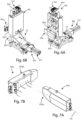
- Figures 4A and 4B show the first pressing device holder module M1, and particularly the first moving unit for moving in depth and height the first pressing device PD1.
- Said first moving unit comprises:
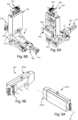
- Figures 6A and 6B show the second pressing device holder module M2, and in particular the second moving unit for moving in depth and in height the second pressing device PD2.
- Said second moving unit comprises:
- Figures 8A and 8B show the third pressing device holder module M3, and in particular the third moving unit for moving in depth and in height the third pressing device PD3.
- Said third moving unit comprises:
- Said first axes x 1 , x 2 , x 3 are parallel each other and said second axes y 1 ,y 2 ,y 3 are parallel each other.
- each pressing device holder module M1, M2, M3 comprises a respective pressing device PD1, PD2, PD3 for exerting a pressure on a respective portion of said edging tape N and a respective moving unit for moving a respective pressing device PD1, PD2, PD3 along two respective axes with respect to the pressing device holder module M1, M2, M3 on which said pressing device PD1, PD2, PD3 is installed.
- each pressing device PD1, PD2, PD3 along the two respective axes are independent of each other.
- the edging machine 1 comprises a control logic unit U, shown in Figures 1 , 2 and 3 .
- Said control logic unit is configured to:
- each moving unit is configured for moving a respective pressing device PD1, PD2, PD3 in the space in such a way as to adjust the depth and height of said pressing device independently of each other based on the profile F of the door on which an edging tape N is applied.
- the edging machine object of the invention offers the possibility of guaranteeing the adhesion of an edging tape N to different types of door profiles since the pressing devices PD1, PD2, PD3 mounted on the respective pressing device holder modules M1, M2, M3 are adjustable in depth and/or height with respect to the basement B of the edging machine 1.
- each pressing device PD1, PD2, PD3 is couplable in a removable manner to a respective pressing device holder module M1, M2, M3.
- a further advantage is given by the fact that it is possible to remove a single pressing device based on the profile F of a door, without the need to remove the remaining pressing devices.
- each pressing device PD1, PD2, PD3 is coupled in a removable manner to a respective a pressing device holder module M1, M2, M3 through a respective supporting element.
- each pressing device PD1, PD2, PD3 is coupled to the respective supporting element through a shape coupling.
- each pressing device PD1, PD2, PD3 can be manually coupled/uncoupled to/from the respective pressing device holder module M1, M2, M3 easily.
- said first pressing device holder module M1 comprises:
- Said first moving device RP1 comprises a first electric motor E11 connected to said first supporting element SE11 through a first slider C1, so that the movement of said first slider C1 in a first direction or in a second direction, opposite to said first direction, causes the movement of said first pressing device holder module M1 in the same direction, along said first axis X1.
- Said further first moving device RA1 comprises a further first electric motor E12 connected to said further first supporting element SE12 through a first screw, preferably a worm screw (which can be a trapezoidal screw or a ball screw), so that the movement of said further first supporting element SE12 in a first direction or in a second direction, opposite to said first direction, causes the movement of said first pressing device PD1 in the same direction, along said second axis y 1 .
- a further first electric motor E12 connected to said further first supporting element SE12 through a first screw, preferably a worm screw (which can be a trapezoidal screw or a ball screw), so that the movement of said further first supporting element SE12 in a first direction or in a second direction, opposite to said first direction, causes the movement of said first pressing device PD1 in the same direction, along said second axis y 1 .
- said second pressing device holder module M2 comprises:
- Said second moving device RP2 comprises a second electric motor E21 connected to said second supporting element SE21 through a second slider C2, so that the movement of said second slider C2 in a first direction or in a second direction, opposite to said first direction, causes the movement of said second pressing device holder module M2 in the same direction, along said first axis x 2 .
- Said further second moving device RA2 comprises a further second electric motor E22 connected to said further second supporting element SE22 through a second screw, preferably a worm screw (which can be a trapezoidal screw or a ball screw), so that the movement of said further second supporting element SE22 in a first direction or in a second direction, opposite to said first direction, causes the movement of said second pressing device PD2 in the same direction, along said second axis y 2 .
- a further second electric motor E22 connected to said further second supporting element SE22 through a second screw, preferably a worm screw (which can be a trapezoidal screw or a ball screw), so that the movement of said further second supporting element SE22 in a first direction or in a second direction, opposite to said first direction, causes the movement of said second pressing device PD2 in the same direction, along said second axis y 2 .
- said third pressing device holder module M3 comprises:
- Said third moving device RP3 comprises a third electric motor E31 connected to said third supporting element E31 through a third slider C3, so that the movement of said third slider C3 in a first direction or in a second direction, opposite to said first direction, causes the movement of said third pressing device holder module M3 in the same direction, along said first axis X3.
- Said further third moving device RA3 comprises a further third electric motor E32 connected to said further third supporting element SE32 through a third screw, preferably a worm screw (which can be a trapezoidal screw or a ball screw), so that the movement of said further third supporting element SE32 in a first direction or in a second direction, opposite to said first direction, causes the movement of said third pressing device PD3 in the same direction, along said second axis y 3 .
- a third screw preferably a worm screw (which can be a trapezoidal screw or a ball screw)
- the control logic unit U can be configured to send a respective control signal to the moving device and/or the further moving device of any moving unit, so that the respective pressing device moves along a respective first axis (in a first direction or second direction) and/or along a respective second axis (in a first direction or second direction) of a respective distance based on the respective control signal sent by the control logic unit U.
- each pressing device PD1, PD2, PD3 of the edging machine 1 has a respective longitudinal axis A1, A2, A3 and a respective single axis of symmetry.
- Said axis of symmetry coincides with said longitudinal axis.
- each pressing device PD1, PD2, PD3 divides each pressing device PD1, PD2, PD3 into two equal parts: a first part or upper part, and a second part or lower part.
- Figures 5A and 5B show the first pressing device PD1.
- Said first pressing device PD1 comprises a first body PD10 which extends along said longitudinal axis A1 from a first end to a second end and has a single axis of symmetry, in which said axis of symmetry coincides with said longitudinal axis A1.
- said first body PD10 is provided with a groove PD10A which extends centrally around said longitudinal axis A1 from said first end to said second end.
- Figures 7A and 7B show the second pressing device PD2.
- Said second pressing device PD2 comprises a second body PD20 which extends along a longitudinal axis A2 from a first end to a second end and has a single axis of symmetry, in which said axis of symmetry coincides with said longitudinal axis A2.
- said second body PD20 has, near said first end, a portion having a truncated pyramid shape with a rectangular base.
- Figures 9A and 9B show the third pressing device PD3.
- Said third pressing device PD3 comprises a third body PD30 which extends along a longitudinal axis A3 from a first end to a second end and has a single axis of symmetry, wherein said axis of symmetry coincides with said longitudinal axis A3.
- said third body PD30 has, near said first end, a portion having a truncated pyramid shape with a rectangular base.
- At least one pressing device between said first pressing device PD1, said second pressing device PD2 and said third pressing device PD3 can comprise a respective cavity (not shown), as well as one or more inlets for the passage of a refrigerant fluid , such as for example cold air, inside said cavity and one or more outlets for the exit of said refrigerant fluid from said pressing device.
- a refrigerant fluid such as for example cold air
- the edging machine 1 comprises an air generator, i.e. a cold air generator.
- each pressing device has a plurality of inlets and a plurality of outlets.
- said first pressing device PD1 comprises a first inlet I 11 and a second inlet I 12 to allow the entry of a refrigerant fluid inside the first pressing device PD1 and a plurality of outlets U 11 , U 12 ,...U 1N .
- Said second pressing device PD2 comprises a first inlet I 21 and a second inlet I 22 to allow the entry of a refrigerant fluid inside the second pressing device PD2 and a plurality of outlets U 21 , U 22 ,...U 2N .
- Said third pressing device PD3 comprises a first inlet I 31 and a second inlet I 32 to allow the entry of a refrigerant fluid inside the third pressing device PD3 and a plurality of outlets U 31 , U 32 ,...U 3N .
- At least a pressing device between said first pressing device PD1, said second pressing device PD2 and said third pressing device PD3 can comprise heating means for heating said at least one pressing device.
- said heating means can comprise a heating fluid, such as a hot air.
- Said heating fluid enters one or more inlets of said at least one pressing device and exits from the respective outlets of said pressing device.
- the edging machine 1 comprises an air generator, i.e. a hot air generator.
- the same inlets of at least one pressing device can be used to allow the passage of a quantity of cold air or hot air inside said pressing device and the same outlets allow said quantity of cold air or hot air to exit the pressing device, depending on the air generator in use.
- said heating means can comprise a resistor arranged inside said at least one pressing device.
- said resistor is included in a heating circuit present inside said pressing device.
- Said heating circuit comprises power supplying means for generating an electric current within said heating circuit.
- Said power supplying means can be turned on and off manually or through the control logic unit U.
- said edging machine 1 can comprise a first roller group RL 11 ,RL 12 ,...RL 1N for exerting a pressure on said edging tape N, as shown in Figure 2 .
- Said first roller group RL 11 ,RL 12 ,...RL 1N is arranged in succession to said third pressing device holder module M3 and comprises a plurality of first rollers RL 11 ,RL 12 ,...RL 1N .
- Each first roller RL 11 ,RL 12 ....RL 1N of said first roller group RL 11 ,RL 12 ,...RL 1N has a respective first axis of rotation r 11 ,r 12 ,...r 1N perpendicular to said longitudinal axis L of the edging machine 1.
- Said first axes of rotation r 11 ,r 12 ,...r 1N are parallel to each other.
- said first roller holder module MR1 comprises a fourth moving unit for moving said first roller group RL 11 , RL 12 , RL 13 in depth and height with respect to said first roller holder group MR1.
- Said fourth moving unit comprises:
- Said first roller holder module MR1 comprises:
- Said fourth moving device RP4 comprises a fourth electric motor E14 connected to said fourth supporting element SE41 through a fourth slider C4, so that the movement of said fourth slider C4 in a first direction or in a second direction, opposite to said first direction, causes the movement of said first roller holder module MR1 in the same direction, along said first axis X4.
- Said further fourth moving device RA4 comprises a further fourth electric motor E42 connected to said further fourth supporting element SE42 through a fourth screw, preferably a worm screw (which can be a trapezoidal screw or a ball screw), so that the movement of said further fourth supporting element SE42 in a first direction or in a second direction, opposite to said first direction, causes the movement of said first roller group RL 11 , RL 12 , RL 13 in the same direction, along said second axis y 4 .
- a fourth screw preferably a worm screw (which can be a trapezoidal screw or a ball screw)
- said first roller group comprises three rollers RL 11 , RL 12 , RL 13 , each of which has a respective first axis of rotation r 11 , r 12 , r 13 .
- the edging machine 1 comprises a second roller group RL 21 ,RL 22 ,...RL 2N to exert a further pressure on said edging tape N, as shown in Figure 2 .
- Said second roller group RL 21 ,RL 22 ,...RL 2N is arranged in succession to said first roller group RL 11 ,RL 12 ,...RL 1N and comprises a plurality of second rollers RL 21 ,RL 22 ,...RL 2N .
- Each second roller RL 21 ,RL 22 ,...RL 2N of said second roller group RL 21 ,RL 22 ,...RL 2N has a respective second axis of rotation r 21 ,r 22 ,...r 2N perpendicular to said longitudinal axis L of the edging machine 1 and to the first axis of rotation r 11 ,r 12 ,... r 1N of the first rollers RL 11 ,RL 12 ....RL 1N of the first roller group RL 11 ,RL 12 ,...RL 1N .
- Said second axis of rotation r 21 ,r 22 ,...r 2N are parallel to each other.
- said second roller group RL 21 ,RL 22 ,...RL 2N is included in a second roller holder module.
- Said fifth moving unit comprises:
- Said second roller holder module MR2 comprises:
- Said fifth moving device RP5 comprises a fifth electric motor E51 connected to said fifth supporting element SE51 through a fifth slider C5, so that the movement of said fifth slider C5 in a first direction or in a second direction, opposite to said first direction, causes the movement of said second roller holder module MR2 in the same direction, along said first axis X5.
- Said further moving device RA5 comprises a further fifth electric motor E52 connected to said further fifth supporting element SE52 through a fifth screw, preferably a worm screw (which can be a trapezoidal screw or a ball screw), so that the movement of said further fifth supporting element SE52 in a first direction or in a second direction, opposite to said first direction, causes the movement of said second roller group RL 21 , RL 22 , RL 23 in the same direction, along said second axis y 5 .
- a fifth screw preferably a worm screw (which can be a trapezoidal screw or a ball screw)
- said first roller group comprises three second rollers RL 21 , RL 22 , RL 23 , each of which has a respective second axis of rotation r 21 , r 22 , r 23 .
- the control logic unit can be configured to send a respective control signal to the moving device and/or to the further moving device of the fourth moving unit and/or of the fifth moving unit, so that the respective roller group moves along a respective first axis (in a first direction or in a second direction) and/or along a respective second axis (in a first direction or in a second direction) of a respective distance based on the respective control signal sent from the control logic unit U.
- the edging machine 1 can comprise a pressing system along said longitudinal axis L before of the first pressing device holder module M1.
- Said pressing system can comprise a roller RL having an axis of rotation r perpendicular to the longitudinal axis L of the edging machine.
- Said roller RL is intended to contact said profile F and to exert a pressure on the edging tape N so that said edging tape N is applied on said profile F.
- said pressing system further comprises a roller group RL 1 ,RL 2 ,...RL N to exert a further pressure on said edging tape N.
- Said roller group RL 1 ,RL 2 ,...RL N is arranged in succession to said roller RL and comprises a plurality of rollers RL 1 ,RL 2 ,...RL N .
- Each roller RL 1 ,RL 2 ,...RL N of said plurality of rollers RL 1 ,RL 2 ,...RL N has a respective axis of rotation r 1 ,r 2 ,...r N parallel to said axis of rotation r of said roller R.
- said edging machine 1 can comprise a supporting device SD for supporting said roller group RL 1 ,RL 2 ,...RL N and said supporting device SD is arranged between a first wall P1 and a second wall P2 of said edging machine 1 and is connected to said two walls P1, P2 in such a way as to rotate around a axis of rotation T parallel to the longitudinal axis L of the edging machine 1.
- Said first wall P1 and said second wall P2 are parallel to each other.
- the rotation of said supporting device SD causes the rotation of said roller group RL 1 ,RL 2 ,...RL N .
- the rotation of said supporting device SD can be manual or motorized (in the latter case an electric motor is connected to the supporting device SD and the control logic unit U can be configured to control said electric motor to rotate the supporting device SD).
- the rotation of said roller group RL 1 ,RL 2 ,...RL N allow to exert a pressure on an edging tape N applied on a profile F of a door, when said profile F has one or more inclined faces, for example when the first face F1 forms with the second face F2 a first angle ⁇ less than 90°.
- said roller group comprises five rollers RL 1 , RL 2 , RL 3 , RL 4 , RL 5 , each of which has a respective axis of rotation r 1 , r 2 , r 3 , r 4 , r 5 .
- said edging machine 1 can comprise at least one first hot air blowing device DA1 for blowing a jet of hot air on the edging tape N applied on the profile F of a door.
- Said first hot air blowing device DA1 is arranged between said pressing system and said first pressing device holder module M1.
- the quantity of glue with which the edging tape N is applied to the profile F of a door can cool over time.
- a jet of hot air on the edging tape N applied on the profile F of the door increases the temperature of the quantity of glue, so that this quantity of glue is still able to carry out its function and the edging tape can adhere correctly to said profile F of said door when it is subjected to a pressure exerted by the pressing devices PD1, PD2, PD3.
- said edging machine 1 comprises a second hot air blowing device DA2 for blowing a jet of hot air on the edging tape N applied on the profile F of a jamb.
- Said second hot air blowing device DA2 is arranged between said pressing system and said first pressing device holder module M1.
- said second hot air blowing device DA2 faces said first hot air blowing device DA1.
- a jet of hot air on the edging tape N applied to the profile of a jamb increases the temperature of the quantity of glue, so that this quantity of glue is still able to perform its function and the edging tape can adhere correctly to said profile of said jamb when it is subjected to pressure exerted by the pressing devices PD1, PD2, PD3.
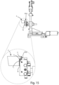
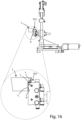
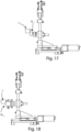
- Figures 14 to 18 schematically show the edging tape applied on the profile F of a door which undergoes a pressure first from the first pressing device ( Figure 14 ), then from the second pressing device ( Figure 15 ), finally from the third pressing device pressing ( Figure 16 ), and subsequently by the first roller group ( Figure 17 ) and by the second roller group ( Figure 18 ).
- Figure 14 shows a first portion of an edging tape N which receives a pressure exerted by the first pressing device PD1 so that said first portion adheres in particular to the first face F1 of the profile F, to the first angle ⁇ and to a portion of the second face F2.
- the first pressing device PD1 can be used for exerting a pressure on a profile of a jamb.
- Figure 15 shows a second portion of an edging tape N which receives a pressure exerted by the second pressing device PD2 so that said second portion adheres in particular to a further portion of the second face F2 of the profile F, to a second angle ⁇ and to a portion of the third face F3 of the profile F.
- the second pressing device PD2 can be used for exerting a pressure on a profile of a jamb.
- a second face F2 of the profile F of a door substantially contacts a first portion (or upper portion) of a first edge (or upper edge)
- a second face of the profile of a jamb will contact a second portion (or lower portion) of a second edge (or lower edge) of the second pressing device PD2.
- Figure 16 shows a third portion of an edging tape N which receives a pressure exerted by the third pressing device PD3 so that said third portion adheres in particular to a further portion of the third face F3 of the profile F.
- the third pressing device PD3 can be also used for exerting a pressure on a profile of a jamb.
- a third face F3 of the profile F of a door substantially contacts a first portion (or upper portion) of the central part of the body PD30 of the third pressing device PD3
- a third face of the profile of a jamb will contact a second portion (or lower portion) of the central part of the body PD30 of the third pressing device PD3.
- Figures 17 and 18 show respectively the profile F of a door on which the edging tape N is applied when a pressure is exerted by the first group of rollers RL 11 ,RL 12 ....RL 1N , included in the first roller holder module MR1, and when a pressure is exerted by a second roller group RL 21 ,RL 22 , ...RL 2N , included in the first roller holder module MR1.
- the pressure exerted by the first roller group and the second roller group improves the adhesion of the edging tape N on the profile F of a door.
- first roller group RL 11 ,RL 12 ,...RL 1N it is possible to exert pressure on the edging tape N against the second face F2 of the profile F of a door
- second roller group RL 21 ,RL 22 ,...RL 2N it is possible to exert pressure on the edging tape N against at least the third face F3 of the profile F of a door.
- Figures 19 and 20 show a variant of the edging machine.
- the pressing system comprises at least a further first roller group R 1 ',R 2 ',...R N ' to exert pressure on a portion of the edging tape N at a first rounded portion of the profile F.
- Said further first roller group comprises a plurality of rollers R 1 ',R 2 ',...R N ' and each roller of said plurality of rollers has a respective axis of rotation r 1 ',r 2 ',...r N ', perpendicular to the longitudinal axis L of the edging machine 1 and parallel to the axis of rotation RL of the roller or to the axis of rotation of the rollers RL 1 , RL 2 ,...RL N of the roller group RL 1 , RL 2 ,...RL N .
- each roller R 1 ' ,R 2 ' ,...R N ' of said further first roller group R 1 ' ,R 2 ' ,...R N ' can be moved in depth along a respective first axis (parallel to the first axes x 1 , x 2 , x 3 mentioned above) through a respective pneumatic actuator (not shown), arranged inside a respective container V 1 ,V 2 ,...V N .
- said container V 1 ,V 2 ,...V N has a cylindrical shape.
- each pneumatic actuator is connected to a respective roller R 1 ' ,R 2 ' ,...R N ' of said further first roller group R 1 ' ,R 2 ' ,...R N ' .
- said further first roller group comprises three rollers R 1 ' ,R 2 ' ,R 3 ' .
- Each roller R 1 ' ,R 2 ' ,R 3 ' has a respective axis of rotation r 1 ' ,r 2 ' ,...r 3 ' .
- the respective first axis along which each roller can be moved in depth is x 6 , x 7 , x 8 .
- said pressing system comprises a further second roller group R 1 " ,R 2 " ,...R N " to exert a pressure on a portion of the edging tape N at a second rounded portion of the profile F (different from the first portion rounded mentioned above).
- Said further second roller group is arranged inside a sector SC included in said edging machine 1, wherein said sector SC is provided with a plurality of slots S 1 ,S 2 ,...S N .
- said further second roller group comprises a plurality of rollers R 1 “ ,R 2 “ ,...R N “ and each roller of said plurality of rollers R 1 “ ,R 2 “ ,...R N “ has a respective axis of rotation r 1 " ,r 2 " ,...r N " and is included in a respective roller holder device PR 1 “ ,PR 2 “ ,...PR N “ .
- Each roller holder device PR 1 " ,PR2 “ ,...PR N” is slidably coupled to a respective slot S 1 ,S 2 ,...S N of said sector SC, so as to slide inside a respective slot S 1 ,S 2 ,...S N up to a desired position, and is provided with respective blocking means to be locked in said desired position along said slot S 1 ,S 2 ,...S N .
- the roller holder device When a desired position is reached, the roller holder device is blocked in said desired position, so that the respective axis of rotation has a certain inclination with respect to the longitudinal axis L of the edging machine 1.
- said blocking means can comprise a respective screw SV 1 ,SV 2 ,...SV N .
- Each slot has an elongated and curvilinear shape.
- said further second roller group comprises four rollers R 1 “ , R 2 “ , R 3 “ , R 4 " capable of rotating around a respective axis of rotation r 1 “ , r 2 “ , r 3 “ , r 4 " and is included in a respective roller holder device PR 1 “ , PR 2 “ , PR 3 “ , PR 4 " .
- Figures 21 and 22 show in detail the further first roller group R 1 ' ,R 2 ' ,R 3 ' and the further second roller group R 1 “ , R 2 “ , R 3 “ , R 4 " respectively.
- Figure 23 show a roller R 1 ' of said further first roller group R 1 ' ,R 2 ' ,R 3 ' which exerts a pressure on the edging tape N at a first rounded portion F of a door.
- said first rounded portion is an end portion of the third face F3 of said profile F.
- Figure 24 show a roller R 1 " of said further second roller group R 1 " ,R 2 " , R 3 , “ R 4 " which exerts a pressure on the edging tape N at a second rounded portion of a profile F of a door.
- said second rounded portion is an end portion of the first face F1 of said profile F.
- the position of said roller R 1 " with respect to the slot S 1 determines the inclination of its axis of rotation r 1 " with respect to the longitudinal axis L of the edging machine 1.
- each roller of said further second roller group R1",R2",R3,”R4" can have a shaped form based on the rounded portion of the profile F.
- the edging machine 1 comprises both said further first roller group and said further second roller group.
- both said further roller groups are both present.
- the edging machine could comprise only the further first roller group or only the further second roller group, without departing from the scope of the invention.
- the edging machine 1 can be used for a greater number of door/jamb profiles, so as to be more flexible in terms of use compared to edging machines of known type.
- the edging machine 1 object of the invention allows the application of an edging tape N not only on different profiles of a door but also on different profiles of a jamb.
- the edging machine 1 object of the invention allows to replace a single pressing device of a pressing device holder module based on the profile of a door/jamb, without the need to dismantle the respective pressing device holder module, nor the other pressing devices of the edging machine.
- the disassembly and assembly operations are reduced to a minimum since it is sufficient to dismantle one or more pressing devices based on the profile of the door/jamb.
- the structure of the edging machine object of the invention is designed to allow even a single pressing device to be dismantled to replace it with a further pressing device.
- dismantle a pressing device (which is removably coupled to the respective pressing device holder module via a coupling element) from the respective pressing device holder module and mount an additional pressing device are simpler operations than dismantling a sector from a known type of edging machine and assembling a further sector.
- the time necessary to dismantle a single pressing device is less than the time necessary to dismantle an entire sector of a known type of edging machine, just as the time to mount just one additional pressing device is less than the time to mount a further sector for an edging machine of known type.
- the possibility of adjusting the depth and height of the individual pressing devices of the edging machine independently of each other increases the number of types of door/jamb profiles that can be machined by said edging machine.
Landscapes
- Engineering & Computer Science (AREA)
- Mechanical Engineering (AREA)
- Manufacturing & Machinery (AREA)
- Life Sciences & Earth Sciences (AREA)
- Chemical & Material Sciences (AREA)
- Combustion & Propulsion (AREA)
- Physics & Mathematics (AREA)
- Thermal Sciences (AREA)
- Wood Science & Technology (AREA)
- Forests & Forestry (AREA)
- Casting Or Compression Moulding Of Plastics Or The Like (AREA)
Applications Claiming Priority (1)
| Application Number | Priority Date | Filing Date | Title |
|---|---|---|---|
| IT102023000012927A IT202300012927A1 (it) | 2023-06-22 | 2023-06-22 | Macchina bordatrice per applicare un nastro di bordatura su una porta/stipite |
Publications (1)
| Publication Number | Publication Date |
|---|---|
| EP4480680A1 true EP4480680A1 (de) | 2024-12-25 |
Family
ID=87974161
Family Applications (1)
| Application Number | Title | Priority Date | Filing Date |
|---|---|---|---|
| EP24183598.2A Pending EP4480680A1 (de) | 2023-06-22 | 2024-06-21 | Kantenanlegemaschine zum aufbringen eines kantenbandes auf ein profil einer tür/eines türpfostens |
Country Status (2)
| Country | Link |
|---|---|
| EP (1) | EP4480680A1 (de) |
| IT (1) | IT202300012927A1 (de) |
Citations (3)
| Publication number | Priority date | Publication date | Assignee | Title |
|---|---|---|---|---|
| CN106903774A (zh) * | 2017-04-17 | 2017-06-30 | 南通跃通数控设备有限公司 | 一种门扇边条涂胶压合修边生产线 |
| KR102300850B1 (ko) * | 2019-12-04 | 2021-09-14 | (주)현대산기 | 에지 밴딩기 |
| CN115535352A (zh) * | 2022-10-14 | 2022-12-30 | 深圳市朗鑫智能科技有限公司 | 一种智能家居用真空绝热板的处理设备及处理方法 |
-
2023
- 2023-06-22 IT IT102023000012927A patent/IT202300012927A1/it unknown
-
2024
- 2024-06-21 EP EP24183598.2A patent/EP4480680A1/de active Pending
Patent Citations (3)
| Publication number | Priority date | Publication date | Assignee | Title |
|---|---|---|---|---|
| CN106903774A (zh) * | 2017-04-17 | 2017-06-30 | 南通跃通数控设备有限公司 | 一种门扇边条涂胶压合修边生产线 |
| KR102300850B1 (ko) * | 2019-12-04 | 2021-09-14 | (주)현대산기 | 에지 밴딩기 |
| CN115535352A (zh) * | 2022-10-14 | 2022-12-30 | 深圳市朗鑫智能科技有限公司 | 一种智能家居用真空绝热板的处理设备及处理方法 |
Also Published As
| Publication number | Publication date |
|---|---|
| IT202300012927A1 (it) | 2024-12-22 |
Similar Documents
| Publication | Publication Date | Title |
|---|---|---|
| EP4480680A1 (de) | Kantenanlegemaschine zum aufbringen eines kantenbandes auf ein profil einer tür/eines türpfostens | |
| US7402096B2 (en) | Device for machining material plates | |
| CN103419123B (zh) | 化学机械研磨装置 | |
| EP1520659B1 (de) | Poliermaschine für Stein- oder Marmorplatten mit einer Schablone | |
| US7909028B2 (en) | Inlaid stone composite | |
| US7094128B2 (en) | Automatic machine for grinding the borders of glass panes | |
| CN111203783A (zh) | 一种用于五金配件加工毛边抛光设备 | |
| HU186764B (en) | Milling tool for profiling respectively trueing grindstones | |
| CN113802813A (zh) | 一种用于内外墙加工的往复式自动喷涂机及其控制方法 | |
| CN102059594A (zh) | 涂布刮刀陶瓷涂层的精密磨削工装夹具、磨削方法及制品 | |
| CN107175571B (zh) | 一种用于汽车制造的高效打磨装置 | |
| WO2013072845A1 (en) | A machine for working slab edges | |
| CN103707153A (zh) | 玻璃磨边机及其磨边加工方法 | |
| EP2527110B1 (de) | Betriebseinheit, insbesondere für Kantenverkleidungsmaschinen | |
| CN116615307A (zh) | 超耐磨的磨削刀具的调整 | |
| CN111455748B (zh) | 一种钢轨廓形在线一次成型铣轨设备及方法 | |
| EP1649975B1 (de) | Vorrichtung für das Herstellen von Kanten mit veränderbaren Schrägen auf dem Rand des Glases, des Marmors, der Stein- oder keramischen Materialplatten und der dergleichen | |
| US20050118928A1 (en) | Machine tool with 5 machining axes with a continuous grinding tool profilling system | |
| US20250214193A1 (en) | Apparatus and method for working sheets | |
| JP2005534523A (ja) | 精密な予備製造コンクリート部材を製造するための方法及び装置 | |
| CN110977670A (zh) | 一种双银可钢化Low-e玻璃加工用双边磨机组 | |
| CA1217056A (en) | Automatic dual compensation grinding wheel conditioner | |
| CN2161419Y (zh) | 一种玻璃磨边机 | |
| CN221048114U (zh) | 一种高精加工的五轴磨床 | |
| CN219819213U (zh) | 一种辊刷刷毛粘结开花修复装置 |
Legal Events
| Date | Code | Title | Description |
|---|---|---|---|
| PUAI | Public reference made under article 153(3) epc to a published international application that has entered the european phase |
Free format text: ORIGINAL CODE: 0009012 |
|
| STAA | Information on the status of an ep patent application or granted ep patent |
Free format text: STATUS: THE APPLICATION HAS BEEN PUBLISHED |
|
| AK | Designated contracting states |
Kind code of ref document: A1 Designated state(s): AL AT BE BG CH CY CZ DE DK EE ES FI FR GB GR HR HU IE IS IT LI LT LU LV MC ME MK MT NL NO PL PT RO RS SE SI SK SM TR |
|
| STAA | Information on the status of an ep patent application or granted ep patent |
Free format text: STATUS: REQUEST FOR EXAMINATION WAS MADE |
|
| 17P | Request for examination filed |
Effective date: 20250623 |
|
| RIC1 | Information provided on ipc code assigned before grant |
Ipc: B29C 65/10 20060101AFI20260324BHEP Ipc: B27D 5/00 20060101ALI20260324BHEP Ipc: B29C 63/00 20060101ALI20260324BHEP Ipc: B29C 63/02 20060101ALI20260324BHEP Ipc: B29C 65/48 20060101ALI20260324BHEP Ipc: B29C 65/00 20060101ALI20260324BHEP Ipc: B29L 31/00 20060101ALN20260324BHEP |