EP4480668A1 - Extrusion apparatus and method for producing resin composition - Google Patents
Extrusion apparatus and method for producing resin composition Download PDFInfo
- Publication number
- EP4480668A1 EP4480668A1 EP22926020.3A EP22926020A EP4480668A1 EP 4480668 A1 EP4480668 A1 EP 4480668A1 EP 22926020 A EP22926020 A EP 22926020A EP 4480668 A1 EP4480668 A1 EP 4480668A1
- Authority
- EP
- European Patent Office
- Prior art keywords
- raw material
- resin raw
- cylinder
- screw
- flow passage
- Prior art date
- Legal status (The legal status is an assumption and is not a legal conclusion. Google has not performed a legal analysis and makes no representation as to the accuracy of the status listed.)
- Pending
Links
Images





Classifications
-
- B—PERFORMING OPERATIONS; TRANSPORTING
- B29—WORKING OF PLASTICS; WORKING OF SUBSTANCES IN A PLASTIC STATE IN GENERAL
- B29C—SHAPING OR JOINING OF PLASTICS; SHAPING OF MATERIAL IN A PLASTIC STATE, NOT OTHERWISE PROVIDED FOR; AFTER-TREATMENT OF THE SHAPED PRODUCTS, e.g. REPAIRING
- B29C48/00—Extrusion moulding, i.e. expressing the moulding material through a die or nozzle which imparts the desired form; Apparatus therefor
- B29C48/25—Component parts, details or accessories; Auxiliary operations
- B29C48/36—Means for plasticising or homogenising the moulding material or forcing it through the nozzle or die
- B29C48/395—Means for plasticising or homogenising the moulding material or forcing it through the nozzle or die using screws surrounded by a cooperating barrel, e.g. single screw extruders
- B29C48/397—Means for plasticising or homogenising the moulding material or forcing it through the nozzle or die using screws surrounded by a cooperating barrel, e.g. single screw extruders using a single screw
-
- B—PERFORMING OPERATIONS; TRANSPORTING
- B29—WORKING OF PLASTICS; WORKING OF SUBSTANCES IN A PLASTIC STATE IN GENERAL
- B29C—SHAPING OR JOINING OF PLASTICS; SHAPING OF MATERIAL IN A PLASTIC STATE, NOT OTHERWISE PROVIDED FOR; AFTER-TREATMENT OF THE SHAPED PRODUCTS, e.g. REPAIRING
- B29C48/00—Extrusion moulding, i.e. expressing the moulding material through a die or nozzle which imparts the desired form; Apparatus therefor
- B29C48/25—Component parts, details or accessories; Auxiliary operations
- B29C48/36—Means for plasticising or homogenising the moulding material or forcing it through the nozzle or die
- B29C48/50—Details of extruders
-
- B—PERFORMING OPERATIONS; TRANSPORTING
- B29—WORKING OF PLASTICS; WORKING OF SUBSTANCES IN A PLASTIC STATE IN GENERAL
- B29B—PREPARATION OR PRETREATMENT OF THE MATERIAL TO BE SHAPED; MAKING GRANULES OR PREFORMS; RECOVERY OF PLASTICS OR OTHER CONSTITUENTS OF WASTE MATERIAL CONTAINING PLASTICS
- B29B7/00—Mixing; Kneading
- B29B7/74—Mixing; Kneading using other mixers or combinations of mixers, e.g. of dissimilar mixers ; Plant
- B29B7/7404—Mixing devices specially adapted for foamable substances
- B29B7/7409—Mixing devices specially adapted for foamable substances with supply of gas
- B29B7/7419—Mixing devices specially adapted for foamable substances with supply of gas with static or injector mixer elements
-
- B—PERFORMING OPERATIONS; TRANSPORTING
- B29—WORKING OF PLASTICS; WORKING OF SUBSTANCES IN A PLASTIC STATE IN GENERAL
- B29C—SHAPING OR JOINING OF PLASTICS; SHAPING OF MATERIAL IN A PLASTIC STATE, NOT OTHERWISE PROVIDED FOR; AFTER-TREATMENT OF THE SHAPED PRODUCTS, e.g. REPAIRING
- B29C48/00—Extrusion moulding, i.e. expressing the moulding material through a die or nozzle which imparts the desired form; Apparatus therefor
- B29C48/25—Component parts, details or accessories; Auxiliary operations
- B29C48/285—Feeding the extrusion material to the extruder
-
- B—PERFORMING OPERATIONS; TRANSPORTING
- B29—WORKING OF PLASTICS; WORKING OF SUBSTANCES IN A PLASTIC STATE IN GENERAL
- B29C—SHAPING OR JOINING OF PLASTICS; SHAPING OF MATERIAL IN A PLASTIC STATE, NOT OTHERWISE PROVIDED FOR; AFTER-TREATMENT OF THE SHAPED PRODUCTS, e.g. REPAIRING
- B29C48/00—Extrusion moulding, i.e. expressing the moulding material through a die or nozzle which imparts the desired form; Apparatus therefor
- B29C48/25—Component parts, details or accessories; Auxiliary operations
- B29C48/36—Means for plasticising or homogenising the moulding material or forcing it through the nozzle or die
- B29C48/362—Means for plasticising or homogenising the moulding material or forcing it through the nozzle or die using static mixing devices
-
- B—PERFORMING OPERATIONS; TRANSPORTING
- B29—WORKING OF PLASTICS; WORKING OF SUBSTANCES IN A PLASTIC STATE IN GENERAL
- B29C—SHAPING OR JOINING OF PLASTICS; SHAPING OF MATERIAL IN A PLASTIC STATE, NOT OTHERWISE PROVIDED FOR; AFTER-TREATMENT OF THE SHAPED PRODUCTS, e.g. REPAIRING
- B29C48/00—Extrusion moulding, i.e. expressing the moulding material through a die or nozzle which imparts the desired form; Apparatus therefor
- B29C48/25—Component parts, details or accessories; Auxiliary operations
- B29C48/36—Means for plasticising or homogenising the moulding material or forcing it through the nozzle or die
- B29C48/50—Details of extruders
- B29C48/505—Screws
- B29C48/63—Screws having sections without mixing elements or threads, i.e. having cylinder shaped sections
-
- B—PERFORMING OPERATIONS; TRANSPORTING
- B29—WORKING OF PLASTICS; WORKING OF SUBSTANCES IN A PLASTIC STATE IN GENERAL
- B29C—SHAPING OR JOINING OF PLASTICS; SHAPING OF MATERIAL IN A PLASTIC STATE, NOT OTHERWISE PROVIDED FOR; AFTER-TREATMENT OF THE SHAPED PRODUCTS, e.g. REPAIRING
- B29C48/00—Extrusion moulding, i.e. expressing the moulding material through a die or nozzle which imparts the desired form; Apparatus therefor
- B29C48/25—Component parts, details or accessories; Auxiliary operations
- B29C48/36—Means for plasticising or homogenising the moulding material or forcing it through the nozzle or die
- B29C48/50—Details of extruders
- B29C48/505—Screws
- B29C48/67—Screws having incorporated mixing devices not provided for in groups B29C48/52 - B29C48/66
-
- B—PERFORMING OPERATIONS; TRANSPORTING
- B29—WORKING OF PLASTICS; WORKING OF SUBSTANCES IN A PLASTIC STATE IN GENERAL
- B29C—SHAPING OR JOINING OF PLASTICS; SHAPING OF MATERIAL IN A PLASTIC STATE, NOT OTHERWISE PROVIDED FOR; AFTER-TREATMENT OF THE SHAPED PRODUCTS, e.g. REPAIRING
- B29C48/00—Extrusion moulding, i.e. expressing the moulding material through a die or nozzle which imparts the desired form; Apparatus therefor
- B29C48/25—Component parts, details or accessories; Auxiliary operations
- B29C48/36—Means for plasticising or homogenising the moulding material or forcing it through the nozzle or die
- B29C48/50—Details of extruders
- B29C48/68—Barrels or cylinders
- B29C48/681—Barrels or cylinders for single screws
-
- B—PERFORMING OPERATIONS; TRANSPORTING
- B29—WORKING OF PLASTICS; WORKING OF SUBSTANCES IN A PLASTIC STATE IN GENERAL
- B29C—SHAPING OR JOINING OF PLASTICS; SHAPING OF MATERIAL IN A PLASTIC STATE, NOT OTHERWISE PROVIDED FOR; AFTER-TREATMENT OF THE SHAPED PRODUCTS, e.g. REPAIRING
- B29C48/00—Extrusion moulding, i.e. expressing the moulding material through a die or nozzle which imparts the desired form; Apparatus therefor
- B29C48/25—Component parts, details or accessories; Auxiliary operations
- B29C48/36—Means for plasticising or homogenising the moulding material or forcing it through the nozzle or die
- B29C48/50—Details of extruders
- B29C48/68—Barrels or cylinders
- B29C48/685—Barrels or cylinders characterised by their inner surfaces, e.g. having grooves, projections or threads
-
- B—PERFORMING OPERATIONS; TRANSPORTING
- B29—WORKING OF PLASTICS; WORKING OF SUBSTANCES IN A PLASTIC STATE IN GENERAL
- B29C—SHAPING OR JOINING OF PLASTICS; SHAPING OF MATERIAL IN A PLASTIC STATE, NOT OTHERWISE PROVIDED FOR; AFTER-TREATMENT OF THE SHAPED PRODUCTS, e.g. REPAIRING
- B29C48/00—Extrusion moulding, i.e. expressing the moulding material through a die or nozzle which imparts the desired form; Apparatus therefor
- B29C48/25—Component parts, details or accessories; Auxiliary operations
- B29C48/36—Means for plasticising or homogenising the moulding material or forcing it through the nozzle or die
- B29C48/50—Details of extruders
- B29C48/695—Flow dividers, e.g. breaker plates
- B29C48/70—Flow dividers, e.g. breaker plates comprising means for dividing, distributing and recombining melt flows
-
- B—PERFORMING OPERATIONS; TRANSPORTING
- B29—WORKING OF PLASTICS; WORKING OF SUBSTANCES IN A PLASTIC STATE IN GENERAL
- B29C—SHAPING OR JOINING OF PLASTICS; SHAPING OF MATERIAL IN A PLASTIC STATE, NOT OTHERWISE PROVIDED FOR; AFTER-TREATMENT OF THE SHAPED PRODUCTS, e.g. REPAIRING
- B29C48/00—Extrusion moulding, i.e. expressing the moulding material through a die or nozzle which imparts the desired form; Apparatus therefor
- B29C48/25—Component parts, details or accessories; Auxiliary operations
- B29C48/36—Means for plasticising or homogenising the moulding material or forcing it through the nozzle or die
- B29C48/50—Details of extruders
- B29C48/74—Bypassing means, i.e. part of the molten material being diverted into downstream stages of the extruder
-
- B—PERFORMING OPERATIONS; TRANSPORTING
- B29—WORKING OF PLASTICS; WORKING OF SUBSTANCES IN A PLASTIC STATE IN GENERAL
- B29C—SHAPING OR JOINING OF PLASTICS; SHAPING OF MATERIAL IN A PLASTIC STATE, NOT OTHERWISE PROVIDED FOR; AFTER-TREATMENT OF THE SHAPED PRODUCTS, e.g. REPAIRING
- B29C48/00—Extrusion moulding, i.e. expressing the moulding material through a die or nozzle which imparts the desired form; Apparatus therefor
- B29C48/25—Component parts, details or accessories; Auxiliary operations
- B29C48/36—Means for plasticising or homogenising the moulding material or forcing it through the nozzle or die
- B29C48/50—Details of extruders
- B29C48/74—Bypassing means, i.e. part of the molten material being diverted into downstream stages of the extruder
- B29C48/745—Bypassing means, i.e. part of the molten material being diverted into downstream stages of the extruder for plasticising or homogenising devices
-
- B—PERFORMING OPERATIONS; TRANSPORTING
- B29—WORKING OF PLASTICS; WORKING OF SUBSTANCES IN A PLASTIC STATE IN GENERAL
- B29C—SHAPING OR JOINING OF PLASTICS; SHAPING OF MATERIAL IN A PLASTIC STATE, NOT OTHERWISE PROVIDED FOR; AFTER-TREATMENT OF THE SHAPED PRODUCTS, e.g. REPAIRING
- B29C48/00—Extrusion moulding, i.e. expressing the moulding material through a die or nozzle which imparts the desired form; Apparatus therefor
- B29C48/25—Component parts, details or accessories; Auxiliary operations
- B29C48/36—Means for plasticising or homogenising the moulding material or forcing it through the nozzle or die
- B29C48/50—Details of extruders
- B29C48/505—Screws
- B29C48/575—Screws provided with elements of a generally circular cross-section for shearing the melt, i.e. shear-ring elements
-
- B—PERFORMING OPERATIONS; TRANSPORTING
- B29—WORKING OF PLASTICS; WORKING OF SUBSTANCES IN A PLASTIC STATE IN GENERAL
- B29C—SHAPING OR JOINING OF PLASTICS; SHAPING OF MATERIAL IN A PLASTIC STATE, NOT OTHERWISE PROVIDED FOR; AFTER-TREATMENT OF THE SHAPED PRODUCTS, e.g. REPAIRING
- B29C48/00—Extrusion moulding, i.e. expressing the moulding material through a die or nozzle which imparts the desired form; Apparatus therefor
- B29C48/25—Component parts, details or accessories; Auxiliary operations
- B29C48/36—Means for plasticising or homogenising the moulding material or forcing it through the nozzle or die
- B29C48/50—Details of extruders
- B29C48/505—Screws
- B29C48/58—Screws provided with seal ring elements, i.e. elements of generally circular and tapered shape for preventing the back flow of the melt
-
- B—PERFORMING OPERATIONS; TRANSPORTING
- B29—WORKING OF PLASTICS; WORKING OF SUBSTANCES IN A PLASTIC STATE IN GENERAL
- B29C—SHAPING OR JOINING OF PLASTICS; SHAPING OF MATERIAL IN A PLASTIC STATE, NOT OTHERWISE PROVIDED FOR; AFTER-TREATMENT OF THE SHAPED PRODUCTS, e.g. REPAIRING
- B29C48/00—Extrusion moulding, i.e. expressing the moulding material through a die or nozzle which imparts the desired form; Apparatus therefor
- B29C48/25—Component parts, details or accessories; Auxiliary operations
- B29C48/36—Means for plasticising or homogenising the moulding material or forcing it through the nozzle or die
- B29C48/50—Details of extruders
- B29C48/505—Screws
- B29C48/59—Screws characterised by details of the thread, i.e. the shape of a single thread of the material-feeding screw
- B29C48/605—Screws characterised by details of the thread, i.e. the shape of a single thread of the material-feeding screw the thread being discontinuous
-
- B—PERFORMING OPERATIONS; TRANSPORTING
- B29—WORKING OF PLASTICS; WORKING OF SUBSTANCES IN A PLASTIC STATE IN GENERAL
- B29C—SHAPING OR JOINING OF PLASTICS; SHAPING OF MATERIAL IN A PLASTIC STATE, NOT OTHERWISE PROVIDED FOR; AFTER-TREATMENT OF THE SHAPED PRODUCTS, e.g. REPAIRING
- B29C48/00—Extrusion moulding, i.e. expressing the moulding material through a die or nozzle which imparts the desired form; Apparatus therefor
- B29C48/25—Component parts, details or accessories; Auxiliary operations
- B29C48/36—Means for plasticising or homogenising the moulding material or forcing it through the nozzle or die
- B29C48/50—Details of extruders
- B29C48/505—Screws
- B29C48/59—Screws characterised by details of the thread, i.e. the shape of a single thread of the material-feeding screw
- B29C48/615—Threads having varying helix angles
-
- B—PERFORMING OPERATIONS; TRANSPORTING
- B29—WORKING OF PLASTICS; WORKING OF SUBSTANCES IN A PLASTIC STATE IN GENERAL
- B29C—SHAPING OR JOINING OF PLASTICS; SHAPING OF MATERIAL IN A PLASTIC STATE, NOT OTHERWISE PROVIDED FOR; AFTER-TREATMENT OF THE SHAPED PRODUCTS, e.g. REPAIRING
- B29C48/00—Extrusion moulding, i.e. expressing the moulding material through a die or nozzle which imparts the desired form; Apparatus therefor
- B29C48/25—Component parts, details or accessories; Auxiliary operations
- B29C48/78—Thermal treatment of the extrusion moulding material or of preformed parts or layers, e.g. by heating or cooling
- B29C48/80—Thermal treatment of the extrusion moulding material or of preformed parts or layers, e.g. by heating or cooling at the plasticising zone, e.g. by heating cylinders
- B29C48/83—Heating or cooling the cylinders
- B29C48/832—Heating
Definitions
- the present disclosure relates to an extrusion apparatus and a method for producing a resin composition.
- an extrusion apparatus has a configuration in which not only a shearing activity but also a stretching activity is imparted to the resin raw material.
- each of extrusion apparatuses of Patent Literatures 1 and 2 has a configuration in which a resin raw material to which a shearing activity is imparted by a screw in a conveying portion, the conveying portion being demarcated by a partition wall portion formed in the screw, flows into a passage formed in the screw so as to connect together neighboring conveying portions, the passage extends in an axis direction of the screw, and is rapidly wrung and a stretching activity is thereby imparted to the resin raw material.
- An extrusion apparatus 1 of the present embodiment is suitable for forming a composite material (that is, a resin composition such as a resin strand, a resin pellet, or a resin film) that is used in, for example, an injection molding machine, an extrusion molding machine, or the like which kneads and extrudes the resin raw material.
- the extrusion apparatus 1 includes a cylinder 2, a hopper 3, a discharge portion 4, a screw 5, a partitioning portion 6, a driving portion 7, and a heating portion 8.
- Fig. 3 is a cross-sectional view illustrating a first portion and a third portion of the cylinder in the extrusion apparatus of the present embodiment.
- the cylinder 2 has a generally cylindrical shape and extends in a Y-axis direction.
- cavity portions 21 and a partition wall portion (second partition wall portion) 22 are formed in an inner peripheral surface of a portion in the cylinder 2 on a Y-axis positive side.
- such a cylinder 2 is configured as division structures that are a first portion 23 in which the cavity portions 21 and the partition wall portion 22 are formed, a second portion 24 in which the hopper 3 is provided, and a third portion 25 as another portion.
- those first portion 23, second portion 24, and third portion 25 can be connected together by using bolts or the like which are caused to pass through through holes of a flange formed in each of those portions, for example.
- the number of divisions of the cylinder 2 is not limited and can appropriately be changed in accordance with a length of the cylinder 2 in the Y-axis direction, a shape of the screw 5, or the like.
- the screw 5 extends in the Y-axis direction and includes a helical flight 51.
- the screw 5 is connected with the driving portion 7 and goes through the internal portion of the cylinder 2, and an end portion of the screw 5 on a Y-axis negative side protrudes from an end portion of the cylinder 2 on the Y-axis negative side.
- Fig. 4 is a perspective view illustrating the screw in the extrusion apparatus of the present embodiment.
- the screw 5 includes a conveying portion 52, a kneading portion 53, and partition wall portions (first partition wall portions) 54.
- the conveying portion 52 conveys the resin raw material to the Y-axis positive side while plasticizing the resin raw material.
- the conveying portion 52 is arranged in internal portions of the second portion 24 and the third portion 25 of the cylinder 2.
- a diameter of the conveying portion 52 (that is, a diameter of an outer peripheral end of a flight 51a of the conveying portion 52) is generally equivalent to inner diameters of the second portion 24 and the third portion 25 of the cylinder 2, for example.
- the kneading portion 53 kneads the resin raw material and conveys that to the Y-axis positive side. As illustrated in Fig. 1 , the kneading portion 53 is arranged on the Y-axis positive side relative to the conveying portion 52 and is arranged in an internal portion of the first portion 23 of the cylinder 2, for example.
- a diameter of the kneading portion 53 (that is, a diameter of an outer peripheral end of a flight 51b of the kneading portion 53) is generally equivalent to an inner diameter of the partitioning portion 6, whose details will be described later, for example.
- the partition wall portion 54 on the Y-axis positive side is arranged at a general center, in the Y-axis direction, in the cavity portion 21 of the cylinder 2 on the Y-axis positive side
- the partition wall portion 54 on the Y-axis negative side is arranged at a general center, in the Y-axis direction, in the cavity portion 21 of the cylinder 2 on the Y-axis negative side.
- no through portion 61 is formed in regions in the partitioning portion 6 which correspond to the partition wall portions 54 of the screw 5, that is, a region between the first region A1 and the second region A2 and a region between the third region A3 and the fourth region A4. Further, no through portion 61 is formed in a region in the partitioning portion 6 which corresponds to the partition wall portion 22 of the cylinder 2, that is, a region between the second region A2 and the third region A3.
- the partitioning portion 6 be fixed to the cylinder 2.
- an engaging portion 62, in a projecting shape, of the partitioning portion 6, the engaging portion 62 protruding in the Y-axis direction be engaged with an engaged portion 26a in a recessed shape which is formed in the lid portion 26 of the cylinder 2 and rotation around the Y axis be thereby restrained.
- the melted resin is pressurized and can thereby strongly be pushed into the cavity portion 21 of the cylinder 2. Accordingly, the through portions 61 of the partitioning portion 6 and the cavity portion 21 of the cylinder 2 can be inhibited from being clogged with the melted resin.
- the melted resin goes through the through portions 61 formed in the third region A3 of the partitioning portion 6 by being pushed by the following melted resin and enters a gap (that is, the groove portion of the third portion 53c of the kneading portion 53 of the screw 5) between a portion, on the Y-axis negative side, of the third portion 53c of the kneading portion 53 of the screw 5 and the partitioning portion 6. Accordingly, the melted resin is rapidly accelerated when the melted resin flows into the through portions 61 of the partitioning portion 6 because the flow passage cross-sectional area rapidly shrinks. Further, the melted resin is rapidly decelerated when the melted resin flows out from the through portions 61 of the partitioning portion 6 because the flow passage cross-sectional area is rapidly enlarged. As a result, the stretching activity is imparted to the melted resin.
- the partition wall portion 22 of the cylinder 2 functions as a guiding portion (second guiding portion) which guides the melted resin from the cavity portion 21 of the cylinder 2 on the Y-axis negative side to the through portions 61 formed in the third region A3 of the partitioning portion 6.
- the melted resin is kneaded while being conveyed to the Y-axis positive side by the third portion 53c of the kneading portion 53 of the screw 5. Accordingly, a sheering activity is imparted to the melted resin.
- the gap between the third portion 53c of the kneading portion 53 of the screw 5 and the partitioning portion 6 forms the flow passage (first flow passage) through which the melted resin goes.
- the cavity portion 21 of the cylinder 2 on the Y-axis positive side, the cavity portion 21 being a gap between the cylinder 2 and the partitioning portion 6, forms the flow passage (second flow passage) through which the melted resin goes.
- the second flow passage is divided by the partition wall portion 22 of the cylinder 2.
- the end portion, on the Y-axis positive side, of the cavity portion 21 of the cylinder 2 on the Y-axis positive side functions as the guiding portion (second guiding portion) which guides the melted resin from the cavity portion 21 of the cylinder 2 on the Y-axis positive side to the through portions 61 formed in the first region A1 of the partitioning portion 6.
- the melted resin is thereafter conveyed to the Y-axis positive side by the first portion 53a of the kneading portion 53 of the screw 5 and is discharged as the composite material from the discharge opening 41 of the discharge portion 4.
- the gap between the first portion 53a of the kneading portion 53 of the screw 5 and the partitioning portion 6 forms the flow passage (first flow passage) through which the melted resin goes.
- the first flow passage is divided by the partition wall portion 54 of the screw 5.
- the extrusion apparatus 1 and the method for producing a composite material according to the present embodiment can impart the stretching activity to the resin raw material while inhibiting clogging with the resin raw material.
- the resin raw material can satisfactorily be guided to the through portions 61 of the partitioning portion 6.
- the through portions 61 of the partitioning portion 6 can be inhibited from being clogged with the resin raw material.
- the flight angle ⁇ 1 of the flight 51b of the kneading portion 53 of the screw 5 is small relatively to the flight angle ⁇ 2 of the flight 51a of the conveying portion 52 of the screw 5
- the conveying force on the resin raw material to the Y-axis positive side in the kneading portion 53 is weakened compared to that in the conveying portion 52 of the screw 5
- the flow of the resin raw material to the X-axis positive side and the Z-axis positive side can be promoted.
- the resin raw material is pressurized and can thereby strongly be pushed into the cavity portion 21 of the cylinder 2. Accordingly, the through portions 61 of the partitioning portion 6 and the second flow passage can be inhibited from being clogged with the melted resin.
- Fig. 7 is a diagram illustrating the dispersion test result of the composite material which was obtained by kneading the resin raw material by using the common two-axis extrusion apparatus.
- Fig. 8 is an enlarged view of an VIII section in Fig. 7 .
- Fig. 9 is a diagram illustrating the dispersion test result of the composite material which was obtained by kneading the resin raw material by using the extrusion apparatus of the present embodiment.
- Fig. 10 is an enlarged view of an X section in Fig. 9 .
- the dispersion test result of a composite material was acquired, the composite material being obtained by kneading polypropylene (80%) and the ethylene-vinylalcohol resin (20%) by rotating the screw 5 with a barrel diameter of 35 mm at 1,300 rpm.
- the average dispersion diameter of the ethylene-vinylalcohol resin was 9.53 ⁇ m; however, as illustrated in Fig. 9 and Fig. 10 , as for the composite material which was obtained by kneading the resin raw material by using the extrusion apparatus 1 of the present embodiment, the average dispersion diameter of the ethylene-vinylalcohol resin was 2.73 ⁇ m.
- the extrusion apparatus 1 of the present embodiment can exhibit high kneading performance compared to the common two-axis extrusion apparatus.
- fine kneading is difficult unless the stretching activity is imparted, but because the extrusion apparatus 1 of the present embodiment was able to realize fine kneading compared to the common two-axis extrusion apparatus, it can be understood that the stretching activity can satisfactorily be imparted to the composite material.
- Fig. 11 is a diagram illustrating tensile elastic moduli of the test specimen, which was shaped from the composite material obtained by kneading the resin raw material by using the common two-axis extrusion apparatus, and the test specimen, which was shaped from the resin raw material kneaded by using the extrusion apparatus of the present embodiment.
- Fig. 12 is a diagram illustrating bending elastic moduli of the test specimen, which was shaped from the resin raw material kneaded by using the common two-axis extrusion apparatus, and the test specimen, which was shaped from the resin raw material kneaded by using the extrusion apparatus of the present embodiment.
- the length of glass fiber of a composite material was acquired, the composite material being obtained by kneading polypropylene (70%) and the glass fiber (30%) as the resin raw materials by rotating the screw with a barrel diameter of 32 mm at 500 rpm, and the tensile elastic modulus and the bending elastic modulus of the test specimen shaped from the composite material were acquired.
- the length of glass fiber of a composite material was acquired, the composite material being obtained by kneading polypropylene (70%) and the glass fiber (30%) as the resin raw materials by rotating the screw 5 with a barrel diameter of 35 mm at 1,300 rpm, and the tensile elastic modulus and the bending elastic modulus of the test specimen shaped from the composite material were acquired.
- the average fiber length of the glass fiber of the composite material which was obtained by performing kneading by using the common two-axis extrusion apparatus, was 0.51 mm.
- the standard deviation of the fiber length of the glass fiber of the composite material was 0.34 mm.
- the average fiber length of the glass fiber of the composite material which was obtained by performing kneading by using the extrusion apparatus of the present embodiment, was 0.36 mm.
- the standard deviation of the fiber length of the glass fiber of the composite material was 0.24 mm.
- the extrusion apparatus 1 of the above embodiment includes two cavity portions 21 but may have a single cavity portion 21 or may have three or more cavity portions 21.
- the number of cavity portions 21 may be set taking into consideration the stretching activity to be imparted to the resin raw material, variation which occurs to the resin raw material due to a temperature rise of the resin raw material when the resin raw material moves between the first flow passage and the second flow passage, and so forth. Further, in accordance with the number of cavity portions 21, arrangement of the partition wall portions of the cylinder 2 and the screw 5 and arrangement of the through portions 61 of the partitioning portion 6 may appropriately be changed.
- the cavity portions 21 are formed in an inner peripheral surface of the cylinder 2, but for example, the cylinder 2 is formed to have a generally equivalent inner diameter, a recessed portion is formed in an outer peripheral surface of the partitioning portion 6, and the cavity portion may thereby be formed between the cylinder 2 and the partitioning portion 6.
- the cavity portion is not limited to a generally cylindrical shape and may be a groove portion or the like which extends in the Y-axis direction.
Landscapes
- Engineering & Computer Science (AREA)
- Mechanical Engineering (AREA)
- Extrusion Moulding Of Plastics Or The Like (AREA)
- Processing And Handling Of Plastics And Other Materials For Molding In General (AREA)
Abstract
Description
- The present disclosure relates to an extrusion apparatus and a method for producing a resin composition.
- In order to enhance kneading performance of a resin raw material, an extrusion apparatus has a configuration in which not only a shearing activity but also a stretching activity is imparted to the resin raw material. For example, each of extrusion apparatuses of
Patent Literatures -
- Patent Literature 1:
Japanese Unexamined Patent Application Publication No. 2015-227053 - Patent Literature 2:
Japanese Unexamined Patent Application Publication No. 2016-203576 - The present applicants found the following problem. Each of extrusion apparatuses of
Patent Literatures - The present disclosure has been made in consideration of such a problem and realizes an extrusion apparatus and a method for producing a resin composition that can impart a stretching activity to a resin raw material while inhibiting clogging with the resin raw material.
- An extrusion apparatus according to one aspect of the present disclosure includes:
- a cylinder to which a resin raw material is supplied from a hopper;
- a discharge portion which is provided in an end portion of the cylinder and discharges the resin raw material which has been kneaded;
- a screw which is rotatably inserted in an internal portion of the cylinder, kneads the resin raw material, and conveys the resin raw material to a side of the discharge portion;
- a partitioning portion which is arranged between the cylinder and the screw and in which a through portion through which the resin raw material goes is formed;
- a first flow passage which is formed between the screw and the partitioning portion and through which the resin raw material goes; and
- a second flow passage which is formed between the cylinder and the partitioning portion and through which the resin raw material goes.
- A method for producing a resin composition according to one aspect of the present disclosure includes:
- a step of conveying a resin raw material, which is supplied to an internal portion of a cylinder, to a side of a discharge portion by a screw;
- a step of causing the resin raw material to enter a first flow passage, which is formed between the screw and a partitioning portion, via a through portion of the partitioning portion, which is arranged between the cylinder and the screw, and of causing the resin raw material to flow in the first flow passage; and
- a step of causing the resin raw material to enter a second flow passage, which is formed between the cylinder and the partitioning portion, via the through portion of the partitioning portion and of causing the resin raw material to flow in the second flow passage, and
- the resin raw material is accelerated when the resin raw material goes through the through portion of the partitioning portion.
- The present disclosure can realize an extrusion apparatus and a method for producing a resin composition that are capable of imparting a stretching activity to a resin raw material while inhibiting clogging with the resin raw material.
-
-
Fig. 1 is a partial cross-sectional view illustrating an extrusion apparatus of an embodiment; -
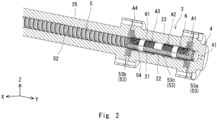
Fig. 2 is a partial cross-sectional view illustrating a side of a discharge portion in the extrusion apparatus of the embodiment while enlarging the side of the discharge portion; -
Fig. 3 is a cross-sectional view illustrating a first portion and a third portion of a cylinder in the extrusion apparatus of the embodiment; -
Fig. 4 is a perspective view illustrating a screw in the extrusion apparatus of the embodiment; -
Fig. 5 is a perspective view illustrating a partitioning portion in the extrusion apparatus of the embodiment; -
Fig. 6 is a diagram for explaining a flow of a resin raw material in a portion on a Y-axis positive side in the cylinder in the extrusion apparatus of the embodiment; -
Fig. 7 is a diagram illustrating a dispersion test result of a composite material which was obtained by kneading the resin raw material by using a common two-axis extrusion apparatus; -
Fig. 8 is an enlarged view of an VIII section inFig. 7 ; -
Fig. 9 is a diagram illustrating a dispersion test result of a composite material which was obtained by kneading the resin raw material by using the extrusion apparatus of the embodiment; -
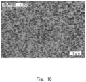
Fig. 10 is an enlarged view of an X section inFig. 9 ; -
Fig. 11 is a diagram illustrating tensile elastic moduli of a test specimen, which was shaped from the composite material obtained by kneading the resin raw material by using the common two-axis extrusion apparatus, and a test specimen, which was shaped from the resin raw material kneaded by using the extrusion apparatus of the present embodiment; and -
Fig. 12 is a diagram illustrating bending elastic moduli of the test specimen, which was shaped from the resin raw material kneaded by using the common two-axis extrusion apparatus, and the test specimen, which was shaped from the resin raw material kneaded by using the extrusion apparatus of the present embodiment. - A specific embodiment to which the present disclosure is applied will hereinafter be described in detail with reference to drawings. However, the present disclosure is not limited by the following embodiment. Further, the following descriptions and drawings are appropriately simplified for the purpose of clarifying the descriptions.
- First, a configuration of an extrusion apparatus of the present embodiment will be described.
Fig. 1 is a partial cross-sectional view illustrating the extrusion apparatus of the present embodiment.Fig. 2 is a partial cross-sectional view illustrating a side of a discharge portion in the extrusion apparatus of the present embodiment while enlarging the side of the discharge portion. - Note that in the following description, in order to make clear the description, the description will be made by using a three-dimensional (XYZ) coordinate system. Here, there are cases where a "resin raw material" in the following description is used as a generic term which includes not only a state where the resin raw material is not yet melted but also a state where that is melted.
- An
extrusion apparatus 1 of the present embodiment is suitable for forming a composite material (that is, a resin composition such as a resin strand, a resin pellet, or a resin film) that is used in, for example, an injection molding machine, an extrusion molding machine, or the like which kneads and extrudes the resin raw material. As illustrated inFig. 1 andFig. 2 , theextrusion apparatus 1 includes acylinder 2, ahopper 3, adischarge portion 4, ascrew 5, a partitioningportion 6, adriving portion 7, and aheating portion 8. -
Fig. 3 is a cross-sectional view illustrating a first portion and a third portion of the cylinder in the extrusion apparatus of the present embodiment. For example, as illustrated inFig. 1 to Fig. 3 , thecylinder 2 has a generally cylindrical shape and extends in a Y-axis direction. In an inner peripheral surface of a portion in thecylinder 2 on a Y-axis positive side,cavity portions 21 and a partition wall portion (second partition wall portion) 22 are formed. - For example, as illustrated in
Fig. 1 to Fig. 3 , thecavity portion 21 is a cylindrical recess portion, which has a large outer diameter compared to a diameter of thepartition wall portion 22, and extends in the Y-axis direction. Thecavity portions 21 are arranged at an interval in the Y-axis direction, for example. - As illustrated in
Fig. 1 to Fig. 3 , thepartition wall portion 22 is arranged between thecavity portions 21 in the Y-axis direction. For example, thepartition wall portion 22 is a cylindrical protrusion portion, which has an inner diameter generally equivalent to an outer diameter of a partitioningportion 6 whose details will be described later, and extends in the Y-axis direction. - For example, as illustrated in
Fig. 1 , such acylinder 2 is configured as division structures that are afirst portion 23 in which thecavity portions 21 and thepartition wall portion 22 are formed, asecond portion 24 in which thehopper 3 is provided, and athird portion 25 as another portion. - Incidentally, those
first portion 23,second portion 24, andthird portion 25 can be connected together by using bolts or the like which are caused to pass through through holes of a flange formed in each of those portions, for example. However, the number of divisions of thecylinder 2 is not limited and can appropriately be changed in accordance with a length of thecylinder 2 in the Y-axis direction, a shape of thescrew 5, or the like. - The
hopper 3 supplies the resin raw material to an internal portion of thecylinder 2. As illustrated inFig. 1 , thehopper 3 is provided in thesecond portion 24 of thecylinder 2. Here, a plurality of kinds of resin raw materials are accommodated in thehopper 3. - The
discharge portion 4 discharges the resin raw material which has been kneaded. As illustrated inFig. 1 andFig. 2 , thedischarge portion 4 is provided in an end portion of thecylinder 2 on the Y-axis positive side and includes adischarge opening 41 which passes through thedischarge portion 4 in the Y-axis direction. - As illustrated in
Fig. 1 , thescrew 5 extends in the Y-axis direction and includes ahelical flight 51. Thescrew 5 is connected with the drivingportion 7 and goes through the internal portion of thecylinder 2, and an end portion of thescrew 5 on a Y-axis negative side protrudes from an end portion of thecylinder 2 on the Y-axis negative side. -
Fig. 4 is a perspective view illustrating the screw in the extrusion apparatus of the present embodiment. As illustrated inFig. 4 , thescrew 5 includes a conveyingportion 52, a kneadingportion 53, and partition wall portions (first partition wall portions) 54. The conveyingportion 52 conveys the resin raw material to the Y-axis positive side while plasticizing the resin raw material. - For example, as illustrated in
Fig. 1 , the conveyingportion 52 is arranged in internal portions of thesecond portion 24 and thethird portion 25 of thecylinder 2. A diameter of the conveying portion 52 (that is, a diameter of an outer peripheral end of aflight 51a of the conveying portion 52) is generally equivalent to inner diameters of thesecond portion 24 and thethird portion 25 of thecylinder 2, for example. - The kneading
portion 53 kneads the resin raw material and conveys that to the Y-axis positive side. As illustrated inFig. 1 , the kneadingportion 53 is arranged on the Y-axis positive side relative to the conveyingportion 52 and is arranged in an internal portion of thefirst portion 23 of thecylinder 2, for example. A diameter of the kneading portion 53 (that is, a diameter of an outer peripheral end of aflight 51b of the kneading portion 53) is generally equivalent to an inner diameter of thepartitioning portion 6, whose details will be described later, for example. - For example, as illustrated in
Fig. 4 , the kneadingportion 53 is arranged at intervals in the Y-axis direction and includes afirst portion 53a on the Y-axis positive side, asecond portion 53b on the Y-axis negative side, and athird portion 53c between thefirst portion 53a and thesecond portion 53b. - In this case, as illustrated in
Fig. 2 , thefirst portion 53a is arranged in a portion, on the Y-axis positive side, of thefirst portion 23 of thecylinder 2. Thesecond portion 53b is arranged in a portion, on the Y-axis negative side, of thefirst portion 23 of thecylinder 2. Thethird portion 53c is arranged across thepartition wall portion 22 of thecylinder 2 at a general center, in the Y-axis direction, in thefirst portion 23 of thecylinder 2. - For example, as illustrated in
Fig. 2 andFig. 4 , thepartition wall portions 54 are arranged between thefirst portion 53a and thethird portion 53c of the kneadingportion 53 and between thethird portion 53c and thesecond portion 53b of the kneadingportion 53. Thepartition wall portion 54 is a cylindrical protrusion portion, which has a diameter generally equivalent to the inner diameter of thepartitioning portion 6 whose details will be described later. - In this case, as illustrated in
Fig. 2 , thepartition wall portion 54 on the Y-axis positive side is arranged at a general center, in the Y-axis direction, in thecavity portion 21 of thecylinder 2 on the Y-axis positive side, and thepartition wall portion 54 on the Y-axis negative side is arranged at a general center, in the Y-axis direction, in thecavity portion 21 of thecylinder 2 on the Y-axis negative side. - Thus, as illustrated in
Fig. 2 , at least a portion, on the Y-axis negative side, of thefirst portion 53a of the kneadingportion 53 is arranged to be covered by a portion, on the Y-axis positive side, of thecavity portion 21 of thecylinder 2 on the Y-axis positive side, and a portion, on the Y-axis positive side, of thethird portion 53c of the kneadingportion 53 is arranged to be covered by a portion, on the Y-axis negative side, of thecavity portion 21 of thecylinder 2 on the Y-axis positive side. - Further, as illustrated in
Fig. 2 , at least a portion, on the Y-axis positive side, of thesecond portion 53b of the kneadingportion 53 is arranged to be covered by a portion, on the Y-axis negative side, of thecavity portion 21 of thecylinder 2 on the Y-axis negative side, and a portion, on the Y-axis negative side, of thethird portion 53c of the kneadingportion 53 is arranged to be covered by a portion, on the Y-axis positive side, of thecavity portion 21 of thecylinder 2 on the Y-axis negative side. - Here, although a detailed mechanism will be described later, as illustrated in
Fig. 4 , it is preferable that a flight angle θ1 of theflight 51b of the kneadingportion 53 be small relatively to a flight angle θ2 of theflight 51a of the conveyingportion 52. - Further, it is preferable that the
second portion 53b be formed such that a depth of a groove portion of a portion, on the Y-axis positive side, of thesecond portion 53b of the kneadingportion 53 becomes shallower toward thepartition wall portion 54 on the Y-axis negative side and that thethird portion 53c be formed such that a depth of a groove portion of a portion, on the Y-axis positive side, of thethird portion 53c of the kneadingportion 53 becomes shallower toward thepartition wall portion 54 on the Y-axis positive side. - For example, as illustrated in
Fig. 1 andFig. 2 , thepartitioning portion 6 is arranged between an inner peripheral surface of thefirst portion 23 of thecylinder 2 and outer peripheral ends of the kneadingportion 53 and thepartition wall portions 54 of thescrew 5.Fig. 5 is a perspective view illustrating the partitioning portion in the extrusion apparatus of the present embodiment. - As illustrated in
Fig. 5 , thepartitioning portion 6 has a generally cylindrical shape, and a plurality of throughportions 61 are formed in thepartitioning portion 6. The outer diameter of thepartitioning portion 6 is generally equivalent to the diameter of thepartition wall portion 22 of thecylinder 2, and the inner diameter of thepartitioning portion 6 is generally equivalent to the diameters of the kneadingportion 53 and thepartition wall portions 54 of thescrew 5. - For example, as illustrated in
Fig. 5 , the throughportion 61 is a circular hole which passes through thepartitioning portion 6 in a thickness direction of thepartitioning portion 6. The plurality of throughportions 61 are respectively formed in a plurality of regions which are arranged at intervals in the Y-axis direction in thepartitioning portion 6. For example, the throughportions 61 are formed in a first region A1, a second region A2, a third region A3, and a fourth region A4 of thepartitioning portion 6. - As illustrated in
Fig. 2 , the first region A1 is a region that covers a portion which is covered by a portion, on the Y-axis positive side, of thecavity portion 21 of thecylinder 2 on the Y-axis positive side in thefirst portion 53a of the kneadingportion 53 of thescrew 5. The second region A2 is a region that covers a portion which is covered by a portion, on the Y-axis negative side, of thecavity portion 21 of thecylinder 2 on the Y-axis positive side in thethird portion 53c of the kneadingportion 53 of thescrew 5. - As illustrated in
Fig. 2 , the third region A3 is a region that covers a portion which is covered by a portion, on the Y-axis positive side, of thecavity portion 21 of thecylinder 2 on the Y-axis negative side in thethird portion 53c of the kneadingportion 53 of thescrew 5. The fourth region A4 is a region that covers a portion which is covered by a portion, on the Y-axis negative side, of thecavity portion 21 of thecylinder 2 on the Y-axis negative side in thesecond portion 53b of the kneadingportion 53 of thescrew 5. - Thus, for example, as illustrated in
Fig. 5 , no throughportion 61 is formed in regions in thepartitioning portion 6 which correspond to thepartition wall portions 54 of thescrew 5, that is, a region between the first region A1 and the second region A2 and a region between the third region A3 and the fourth region A4. Further, no throughportion 61 is formed in a region in thepartitioning portion 6 which corresponds to thepartition wall portion 22 of thecylinder 2, that is, a region between the second region A2 and the third region A3. - Note that a ratio (extent) of the through
portions 61 for a unit area in the first region A1, the second region A2, the third region A3, and the fourth region A4 can be set taking into consideration a stretching activity to be imparted to the resin raw material, flowability of the resin raw material, and so forth. - Here, in order that the
partitioning portion 6 can be inserted into the internal portion of thefirst portion 23 of thecylinder 2 in the Y-axis direction, as illustrated inFig. 2 andFig. 3 , it is preferable that thecylinder 2 includeannular lid portions 26, which are detachable, in the end portion on the Y-axis positive side and the end portion on the Y-axis negative side of thecylinder 2. - In this case, as illustrated in
Fig. 3 , it is preferable that an end portion, on the Y-axis positive side, of thecavity portion 21 of thecylinder 2 on the Y-axis positive side (that is, a side wall portion, on the Y-axis positive side, of thecavity portion 21 on the Y-axis positive side) be formed by an end portion, around the through portions on the Y-axis negative side, of thelid portion 26 on the Y-axis positive side. - Further, as illustrated in
Fig. 3 , it is preferable that an end portion, on the Y-axis negative side, of thecavity portion 21 of thecylinder 2 on the Y-axis negative side (that is, a side wall portion, on the Y-axis negative side, of thecavity portion 21 on the Y-axis negative side) be formed by an end portion, around the through portions on the Y-axis positive side, of thelid portion 26 on the Y-axis negative side. - In addition, it is preferable that the
partitioning portion 6 be fixed to thecylinder 2. For example, it is preferable that an engagingportion 62, in a projecting shape, of thepartitioning portion 6, the engagingportion 62 protruding in the Y-axis direction, be engaged with an engagedportion 26a in a recessed shape which is formed in thelid portion 26 of thecylinder 2 and rotation around the Y axis be thereby restrained. - The driving
portion 7 rotates and drives thescrew 5. As illustrated inFig. 1 , the drivingportion 7 is connected with the end portion of thescrew 5 on the Y-axis negative side such that a driving force is capable of being transmitted. Theheating portion 8 heats the resin raw material supplied to the internal portion of thecylinder 2 and thereby melts the resin raw material. Theheating portion 8 can be configured with a sheet heater, for example, and is wound around an outer peripheral surface of thecylinder 2. - Next, a description will be made about a flow of the resin raw material in producing a composite material by using the
extrusion apparatus 1 of the present embodiment.Fig. 6 is a diagram for explaining the flow of the resin raw material in a portion on the Y-axis positive side in the cylinder in the extrusion apparatus of the present embodiment. Note that inFig. 6 , the flow of the resin raw material is indicated by arrows. - First, the resin raw material supplied from the
hopper 3 to thecylinder 2 is plasticized while being conveyed to the Y-axis positive side by the conveyingportion 52 of thescrew 5 and is melted by being heated by theheating portion 8. - When a melted resin enters a gap (that is, the groove portion of the
second portion 53b of the kneadingportion 53 of the screw 5) between thesecond portion 53b of the kneadingportion 53 of thescrew 5 and thepartitioning portion 6 by being pushed by a following melted resin and reaches the vicinity of thepartition wall portion 54 of thescrew 5 on the Y-axis negative side, the flow of the melted resin to the Y-axis positive side is dammed by thepartition wall portion 54 of thescrew 5 on the Y-axis negative side and is thereby decelerated. In this case, the gap between thesecond portion 53b of the kneadingportion 53 of thescrew 5 and thepartitioning portion 6 forms a flow passage (first flow passage) through which the melted resin goes. - The melted resin goes through the through
portions 61 formed in the fourth region A4 of thepartitioning portion 6 by being pushed by the following melted resin and by rotation of the kneadingportion 53 of thescrew 5 and enters thecavity portion 21 of thecylinder 2 on the Y-axis negative side. Accordingly, the melted resin is rapidly accelerated when the melted resin flows into the throughportions 61 of thepartitioning portion 6 because a flow passage cross-sectional area rapidly shrinks. Further, the melted resin is rapidly decelerated when the melted resin flows out from the throughportions 61 of thepartitioning portion 6 because the flow passage cross-sectional area is rapidly enlarged. As a result, the stretching activity is imparted to the melted resin. - In this case, the
partition wall portion 54 of thescrew 5 on the Y-axis negative side functions as a guiding portion (first guiding portion) which guides the melted resin from the gap between thesecond portion 53b of the kneadingportion 53 of thescrew 5 and thepartitioning portion 6 to the throughportions 61 formed in the fourth region A4 of thepartitioning portion 6. - Further, the through
portion 61 formed in the fourth region A4 of thepartitioning portion 6 functions as a flow-out hole which causes the melted resin to flow out from the gap between thesecond portion 53b of the kneadingportion 53 of thescrew 5 and thepartitioning portion 6 to thecavity portion 21 of thecylinder 2 on the Y-axis negative side. - Here, because the
second portion 53b is formed such that the groove portion of thesecond portion 53b of the kneadingportion 53 of thescrew 5 becomes shallower toward thepartition wall portion 54 on the Y-axis negative side, the melted resin can satisfactorily be guided to the throughportions 61 formed in the fourth region A4 of thepartitioning portion 6. - When the melted resin flows to the Y-axis positive side in the
cavity portion 21 of thecylinder 2 on the Y-axis negative side by being pushed by the following melted resin, the flow of the melted resin to the Y-axis positive side is dammed by thepartition wall portion 22 of thecylinder 2 and is thereby decelerated. In this case, thecavity portion 21 of thecylinder 2 on the Y-axis negative side, thecavity portion 21 being a gap between thecylinder 2 and thepartitioning portion 6, forms a flow passage (second flow passage) through which the melted resin goes. - Here, in a case where the flight angle θ1 of the
flight 51b of the kneadingportion 53 of thescrew 5 is small relatively to the flight angle θ2 of theflight 51a of the conveyingportion 52 of thescrew 5, while a conveying force to the Y-axis positive side in the kneadingportion 53 is weakened compared to that in the conveyingportion 52 of thescrew 5, a flow of the melted resin to an X-axis positive side and a Z-axis positive side can be promoted. - Thus, the melted resin is pressurized and can thereby strongly be pushed into the
cavity portion 21 of thecylinder 2. Accordingly, the throughportions 61 of thepartitioning portion 6 and thecavity portion 21 of thecylinder 2 can be inhibited from being clogged with the melted resin. - The melted resin goes through the through
portions 61 formed in the third region A3 of thepartitioning portion 6 by being pushed by the following melted resin and enters a gap (that is, the groove portion of thethird portion 53c of the kneadingportion 53 of the screw 5) between a portion, on the Y-axis negative side, of thethird portion 53c of the kneadingportion 53 of thescrew 5 and thepartitioning portion 6. Accordingly, the melted resin is rapidly accelerated when the melted resin flows into the throughportions 61 of thepartitioning portion 6 because the flow passage cross-sectional area rapidly shrinks. Further, the melted resin is rapidly decelerated when the melted resin flows out from the throughportions 61 of thepartitioning portion 6 because the flow passage cross-sectional area is rapidly enlarged. As a result, the stretching activity is imparted to the melted resin. - In this case, the
partition wall portion 22 of thecylinder 2 functions as a guiding portion (second guiding portion) which guides the melted resin from thecavity portion 21 of thecylinder 2 on the Y-axis negative side to the throughportions 61 formed in the third region A3 of thepartitioning portion 6. - Further, the through
portion 61 formed in the third region A3 of thepartitioning portion 6 functions as a flow-in hole which causes the melted resin to flow from thecavity portion 21 of thecylinder 2 on the Y-axis negative side into a gap between thethird portion 53c of the kneadingportion 53 of thescrew 5 and thepartitioning portion 6. - The melted resin is kneaded while being conveyed to the Y-axis positive side by the
third portion 53c of the kneadingportion 53 of thescrew 5. Accordingly, a sheering activity is imparted to the melted resin. In this case, the gap between thethird portion 53c of the kneadingportion 53 of thescrew 5 and thepartitioning portion 6 forms the flow passage (first flow passage) through which the melted resin goes. - When the melted resin flows to the Y-axis positive side by being pushed by the following melted resin, the flow of the melted resin to the Y-axis positive side is dammed by the
partition wall portion 54 of thescrew 5 on the Y-axis positive side and is thereby decelerated. The melted resin goes through the throughportions 61 formed in the second region A2 of thepartitioning portion 6 by being pushed by the following melted resin and enters thecavity portion 21 of thecylinder 2 on the Y-axis positive side. Accordingly, the melted resin is rapidly accelerated when the melted resin flows into the throughportions 61 of thepartitioning portion 6 because the flow passage cross-sectional area rapidly shrinks. Further, the melted resin is rapidly decelerated when the melted resin flows out from the throughportions 61 of thepartitioning portion 6 because the flow passage cross-sectional area is rapidly enlarged. As a result, the stretching activity is imparted to the melted resin. - In this case, the
partition wall portion 54 of thescrew 5 on the Y-axis positive side functions as the guiding portion (first guiding portion) which guides the melted resin from the gap between thethird portion 53c of the kneadingportion 53 of thescrew 5 and thepartitioning portion 6 to the throughportions 61 formed in the second region A2 of thepartitioning portion 6. - Further, the through
portion 61 formed in the second region A2 of thepartitioning portion 6 functions as a flow-out hole which causes the melted resin to flow out from the gap between thethird portion 53c of the kneadingportion 53 of thescrew 5 and thepartitioning portion 6 to thecavity portion 21 of thecylinder 2 on the Y-axis positive side. - Here, because the
third portion 53c is formed such that the groove portion of thethird portion 53c of the kneadingportion 53 of thescrew 5 becomes shallower toward thepartition wall portion 54 on the Y-axis positive side, the melted resin can satisfactorily be guided to the throughportions 61 formed in the second region A2 of thepartitioning portion 6. - When the melted resin flows to the Y-axis positive side in the
cavity portion 21 of thecylinder 2 on the Y-axis positive side by being pushed by the following melted resin, the flow of the melted resin to the Y-axis positive side is dammed by the end portion, on the Y-axis positive side, of thecavity portion 21 of thecylinder 2 on the Y-axis positive side and is thereby decelerated. - In this case, the
cavity portion 21 of thecylinder 2 on the Y-axis positive side, thecavity portion 21 being a gap between thecylinder 2 and thepartitioning portion 6, forms the flow passage (second flow passage) through which the melted resin goes. Thus, in the present embodiment, the second flow passage is divided by thepartition wall portion 22 of thecylinder 2. - The melted resin goes through the through
portions 61 formed in the first region A1 of thepartitioning portion 6 by being pushed by the following melted resin and enters a gap (that is, a groove portion of thefirst portion 53a of the kneadingportion 53 of the screw 5) between thefirst portion 53a of the kneadingportion 53 of thescrew 5 and thepartitioning portion 6. Accordingly, the melted resin is rapidly accelerated when the melted resin flows into the throughportions 61 of thepartitioning portion 6 because the flow passage cross-sectional area rapidly shrinks. Further, the melted resin is rapidly decelerated when the melted resin flows out from the throughportions 61 of thepartitioning portion 6 because the flow passage cross-sectional area is rapidly enlarged. As a result, the stretching activity is imparted to the melted resin. - In this case, the end portion, on the Y-axis positive side, of the
cavity portion 21 of thecylinder 2 on the Y-axis positive side functions as the guiding portion (second guiding portion) which guides the melted resin from thecavity portion 21 of thecylinder 2 on the Y-axis positive side to the throughportions 61 formed in the first region A1 of thepartitioning portion 6. - Further, the through
portion 61 formed in the first region A1 of thepartitioning portion 6 functions as a flow-in hole which causes the melted resin to flow from thecavity portion 21 of thecylinder 2 on the Y-axis positive side into the gap between thefirst portion 53a of the kneadingportion 53 of thescrew 5 and thepartitioning portion 6. - The melted resin is thereafter conveyed to the Y-axis positive side by the
first portion 53a of the kneadingportion 53 of thescrew 5 and is discharged as the composite material from the discharge opening 41 of thedischarge portion 4. In this case, the gap between thefirst portion 53a of the kneadingportion 53 of thescrew 5 and thepartitioning portion 6 forms the flow passage (first flow passage) through which the melted resin goes. Thus, in the present embodiment, the first flow passage is divided by thepartition wall portion 54 of thescrew 5. - As described above, in the
extrusion apparatus 1 and a method for producing a composite material according to the present embodiment, the resin raw material is caused to flow between the first flow passage and the second flow passage via the throughportions 61 of thepartitioning portion 6, and not only the sheering activity but also the stretching activity is thereby imparted to the resin raw material. - In this case, because the second flow passage is formed between the
cylinder 2 and thepartitioning portion 6 and can secure a large space compared to flow passages ofPatent Literatures extrusion apparatus 1 and the method for producing a composite material according to the present embodiment can impart the stretching activity to the resin raw material while inhibiting clogging with the resin raw material. - In addition, in the
extrusion apparatus 1 and the method for producing a composite material according to the present embodiment, because the end portion of thecavity portion 21 of thecylinder 2 and thepartition wall portions 54 of thescrew 5 can be caused to function as the guiding portions for the resin raw material, the resin raw material can satisfactorily be guided to the throughportions 61 of thepartitioning portion 6. - In particular, in a case where the
second portion 53b and thethird portion 53c are formed such that the depths of the groove portions of thesecond portion 53b and thethird portion 53c of the kneadingportion 53 of thescrew 5 become shallower toward the Y-axis positive side, the resin raw material can satisfactorily be guided to the throughportions 61 of thepartitioning portion 6. Thus, the throughportions 61 of thepartitioning portion 6 can be inhibited from being clogged with the resin raw material. - Further, in a case where the flight angle θ1 of the
flight 51b of the kneadingportion 53 of thescrew 5 is small relatively to the flight angle θ2 of theflight 51a of the conveyingportion 52 of thescrew 5, while the conveying force on the resin raw material to the Y-axis positive side in the kneadingportion 53 is weakened compared to that in the conveyingportion 52 of thescrew 5, the flow of the resin raw material to the X-axis positive side and the Z-axis positive side can be promoted. Thus, the resin raw material is pressurized and can thereby strongly be pushed into thecavity portion 21 of thecylinder 2. Accordingly, the throughportions 61 of thepartitioning portion 6 and the second flow passage can be inhibited from being clogged with the melted resin. - Next, a description will be made about comparison results of a dispersion test result of a composite material, which was obtained by kneading the resin raw material by using a common two-axis extrusion apparatus, and a dispersion test result of a composite material, which was obtained by kneading the resin raw material by using the
extrusion apparatus 1 of the present embodiment. -
Fig. 7 is a diagram illustrating the dispersion test result of the composite material which was obtained by kneading the resin raw material by using the common two-axis extrusion apparatus.Fig. 8 is an enlarged view of an VIII section inFig. 7 .Fig. 9 is a diagram illustrating the dispersion test result of the composite material which was obtained by kneading the resin raw material by using the extrusion apparatus of the present embodiment.Fig. 10 is an enlarged view of an X section inFig. 9 . - Here, as for the common two-axis extrusion apparatus, the dispersion test result of a composite material was acquired, the composite material being obtained by kneading polypropylene (80%) and an ethylene-vinylalcohol resin (20%) by rotating a screw with a barrel diameter of 32 mm at 500 rpm.
- Further, as for the
extrusion apparatus 1 of the present embodiment, the dispersion test result of a composite material was acquired, the composite material being obtained by kneading polypropylene (80%) and the ethylene-vinylalcohol resin (20%) by rotating thescrew 5 with a barrel diameter of 35 mm at 1,300 rpm. - As illustrated in
Fig. 7 andFig. 8 , as for the composite material which was obtained by kneading the resin raw material by using the common two-axis extrusion apparatus, the average dispersion diameter of the ethylene-vinylalcohol resin was 9.53 µm; however, as illustrated inFig. 9 andFig. 10 , as for the composite material which was obtained by kneading the resin raw material by using theextrusion apparatus 1 of the present embodiment, the average dispersion diameter of the ethylene-vinylalcohol resin was 2.73 µm. - Accordingly, it can be understood that the
extrusion apparatus 1 of the present embodiment can exhibit high kneading performance compared to the common two-axis extrusion apparatus. In particular, as for the above-described resin raw material, fine kneading is difficult unless the stretching activity is imparted, but because theextrusion apparatus 1 of the present embodiment was able to realize fine kneading compared to the common two-axis extrusion apparatus, it can be understood that the stretching activity can satisfactorily be imparted to the composite material. - Next, a description will be made about comparison results of mechanical strength of a test specimen, which was shaped from the composite material obtained by kneading the resin raw material by using the common two-axis extrusion apparatus, and mechanical strength of a test specimen, which was shaped from the composite material obtained by kneading the resin raw material by using the
extrusion apparatus 1 of the present embodiment. -
Fig. 11 is a diagram illustrating tensile elastic moduli of the test specimen, which was shaped from the composite material obtained by kneading the resin raw material by using the common two-axis extrusion apparatus, and the test specimen, which was shaped from the resin raw material kneaded by using the extrusion apparatus of the present embodiment.Fig. 12 is a diagram illustrating bending elastic moduli of the test specimen, which was shaped from the resin raw material kneaded by using the common two-axis extrusion apparatus, and the test specimen, which was shaped from the resin raw material kneaded by using the extrusion apparatus of the present embodiment. - As for the common two-axis extrusion apparatus, the length of glass fiber of a composite material was acquired, the composite material being obtained by kneading polypropylene (70%) and the glass fiber (30%) as the resin raw materials by rotating the screw with a barrel diameter of 32 mm at 500 rpm, and the tensile elastic modulus and the bending elastic modulus of the test specimen shaped from the composite material were acquired.
- Further, as for the
extrusion apparatus 1 of the present embodiment, the length of glass fiber of a composite material was acquired, the composite material being obtained by kneading polypropylene (70%) and the glass fiber (30%) as the resin raw materials by rotating thescrew 5 with a barrel diameter of 35 mm at 1,300 rpm, and the tensile elastic modulus and the bending elastic modulus of the test specimen shaped from the composite material were acquired. - The average fiber length of the glass fiber of the composite material, which was obtained by performing kneading by using the common two-axis extrusion apparatus, was 0.51 mm. In this case, the standard deviation of the fiber length of the glass fiber of the composite material was 0.34 mm.
- On the other hand, the average fiber length of the glass fiber of the composite material, which was obtained by performing kneading by using the extrusion apparatus of the present embodiment, was 0.36 mm. In this case, the standard deviation of the fiber length of the glass fiber of the composite material was 0.24 mm.
- As illustrated in
Fig. 11 , the tensile elastic modulus of the test specimen of the composite material obtained by using theextrusion apparatus 1 of the present embodiment is low compared to the tensile elastic modulus of the test specimen of the composite material obtained by using the common two-axis extrusion apparatus, but a lowering rate of the tensile elastic modulus remained at 11%. - On the other hand, as for the bending elastic modulus of the test specimen of the composite material obtained by using the
extrusion apparatus 1 of the present embodiment, as illustrated inFig. 12 , the length of the glass fiber of the composite material obtained by using theextrusion apparatus 1 is short compared to the length of the glass fiber of the composite material obtained by using the common two-axis extrusion apparatus, but a result was obtained that the bending elastic modulus of the test specimen of the composite material obtained by using theextrusion apparatus 1 is 5% high compared to the bending elastic modulus of the test specimen of the composite material obtained by using the common two-axis extrusion apparatus. - Based on such results, the relationship between the bending elastic modulus of the test specimen of the composite material obtained by using the
extrusion apparatus 1 of the present embodiment and the bending elastic modulus of the test specimen of the composite material obtained by using the common two-axis extrusion apparatus is inverse to the relationship between the length of the glass fiber of the composite material obtained by using theextrusion apparatus 1 and the length of the glass fiber of the composite material obtained by using the common two-axis extrusion apparatus; however, it is considered that high dispersibility of the fiber itself contributes to an improvement in bending strength more than the fiber length of the glass fiber of the composite material does. In other words, it can be under stood that when fine dispersion of the glass fiber can be realized in the resin raw material even when the glass fiber is fractured and becomes short due to kneading, an improvement in mechanical strength can be expected, and in a case where theextrusion apparatus 1 of the present embodiment is used, an improvement in the mechanical strength can be realized. - Consequently, for example, when a composite material is again obtained by using resin pieces whose glass fiber becomes short when a resin product is pulverized for recycle, in a case where the
extrusion apparatus 1 of the present embodiment is used, a recycled product with high mechanical strength can be obtained. - The present disclosure is not limited to the above embodiment but can appropriately be changed without departing from the scope of the gist thereof.
- The
extrusion apparatus 1 of the above embodiment is configured as a single-axis extrusion apparatus but may be configured as an extrusion apparatus which includes a plurality of screws. - The
extrusion apparatus 1 of the above embodiment includes twocavity portions 21 but may have asingle cavity portion 21 or may have three ormore cavity portions 21. In this case, the number ofcavity portions 21 may be set taking into consideration the stretching activity to be imparted to the resin raw material, variation which occurs to the resin raw material due to a temperature rise of the resin raw material when the resin raw material moves between the first flow passage and the second flow passage, and so forth. Further, in accordance with the number ofcavity portions 21, arrangement of the partition wall portions of thecylinder 2 and thescrew 5 and arrangement of the throughportions 61 of thepartitioning portion 6 may appropriately be changed. - In the above embodiment, the
cavity portions 21 are formed in an inner peripheral surface of thecylinder 2, but for example, thecylinder 2 is formed to have a generally equivalent inner diameter, a recessed portion is formed in an outer peripheral surface of thepartitioning portion 6, and the cavity portion may thereby be formed between thecylinder 2 and thepartitioning portion 6. Further, the cavity portion is not limited to a generally cylindrical shape and may be a groove portion or the like which extends in the Y-axis direction. - In the above embodiment, the
partitioning portion 6 having a cylindrical shape is used, but it is sufficient that thepartitioning portion 6 has a shape which can partition the first flow passage from the second flow passage, and thepartitioning portion 6 can appropriately be changed in accordance with a shape or the like of the cavity portion, for example. Further, the throughportion 61 of thepartitioning portion 6 is not limited to a circular shape and may have a polygonal shape, an elliptic shape, or the like. - The present application claims priority based on
Japanese Patent Application No. 2022-20225, filed on February 14, 2022 -
- 1
- EXTRUSION APPARATUS
- 2
- CYLINDER
- 23
- FIRST PORTION
- 24
- SECOND PORTION
- 25
- THIRD PORTION
- 21
- CAVITY PORTION
- 22
- PARTITION WALL PORTION
- 26
- LID PORTION
- 26a
- ENGAGED PORTION
- 3
- HOPPER
- 4
- DISCHARGE PORTION
- 41
- DISCHARGE OPENING
- 5
- SCREW
- 51
- FLIGHT
- 51a
- FLIGHT OF CONVEYING PORTION
- 51b
- FLIGHT OF KNEADING PORTION
- 52
- CONVEYING PORTION
- 53
- KNEADING PORTION
- 53a
- FIRST PORTION
- 53b
- SECOND PORTION
- 53c
- THIRD PORTION
- 54
- PARTITION WALL PORTION
- θ1
- FLIGHT ANGLE OF FLIGHT OF KNEADING PORTION OF SCREW
- θ2
- FLIGHT ANGLE OF FLIGHT OF CONVEYING PORTION OF SCREW
- 6
- PARTITIONING PORTION
- A1
- FIRST REGION
- A2
- SECOND REGION
- A3
- THIRD REGION
- A4
- FOURTH REGION
- 61
- THROUGH PORTION
- 62
- ENGAGING PORTION
- 7
- DRIVING PORTION
- 8
- HEATING PORTION
Claims (13)
- An extrusion apparatus comprising:a cylinder to which a resin raw material is supplied from a hopper;a discharge portion which is provided in an end portion of the cylinder and discharges the resin raw material which has been kneaded;a screw which is rotatably inserted in an internal portion of the cylinder, kneads the resin raw material, and conveys the resin raw material to a side of the discharge portion;a partitioning portion which is arranged between the cylinder and the screw and in which a through portion through which the resin raw material goes is formed;a first flow passage which is formed between the screw and the partitioning portion and through which the resin raw material goes; anda second flow passage which is formed between the cylinder and the partitioning portion and through which the resin raw material goes.
- The extrusion apparatus according to claim 1, comprising a first guiding portion which guides the resin raw material from the first flow passage to the through portion of the partitioning portion.
- The extrusion apparatus according to claim 1 or 2, comprising a second guiding portion which guides the resin raw material from the second flow passage to the through portion of the partitioning portion.
- The extrusion apparatus according to any one of claims 1 to 3, whereinthe screw includes a conveying portion which conveys the resin raw material and a kneading portion which is arranged on a side of the discharge portion relative to the conveying portion and kneads the resin raw material, andthe partitioning portion is arranged in a position corresponding to the kneading portion of the screw.
- The extrusion apparatus according to claim 4, wherein a flight angle of the kneading portion in the screw is small relatively to a flight angle of the conveying portion in the screw.
- The extrusion apparatus according to any one of claims 1 to 5, wherein the partitioning portion has a cylindrical shape, which covers the screw, and includes a plurality of holes as the through portion.
- The extrusion apparatus according to claim 6, wherein the partitioning portion is fixed to the cylinder.
- The extrusion apparatus according to claim 6 or 7, wherein the partitioning portion includes a plurality of flow-out holes which cause the resin raw material to flow out from the first flow passage to the second flow passage and a plurality of flow-in holes which cause the resin raw material to flow from the second flow passage into the first flow passage.
- The extrusion apparatus according to claim 8, comprising a first partition wall portion that divides the first flow passage between the flow-out holes and the flow-in holes which are arranged on a side of the discharge portion relative to the flow-out holes in an axis direction of the screw,
wherein the first flow passage is arranged such that the second flow passage is interposed in the first flow passage. - The extrusion apparatus according to claim 9, whereinthe screw includes a conveying portion which conveys the resin raw material, a kneading portion which is arranged on a side of the discharge portion relative to the conveying portion and kneads the resin raw material, and the first partition wall portion, anda depth of a groove portion of a portion on a side of the first partition wall portion in the kneading portion becomes shallower toward the side of the first partition wall portion.
- The extrusion apparatus according to any one of claims 8 to 10, comprising a second partition wall portion that divides the second flow passage between the flow-in holes and the flow-out holes which are arranged on a side of the discharge portion relative to the flow-in holes in an axis direction of the cylinder,
wherein the second flow passage is arranged such that the first flow passage is interposed in the second flow passage. - The extrusion apparatus according to any one of claims 1 to 11, wherein the second flow passage is a recess portion which is formed in an inner peripheral surface of the cylinder.
- A method for producing a resin composition, the method comprising:a step of conveying a resin raw material, which is supplied to an internal portion of a cylinder, to a side of a discharge portion by a screw;a step of causing the resin raw material to enter a first flow passage, which is formed between the screw and a partitioning portion, via a through portion of the partitioning portion, which is arranged between the cylinder and the screw, and of causing the resin raw material to flow in the first flow passage; anda step of causing the resin raw material to enter a second flow passage, which is formed between the cylinder and the partitioning portion, via the through portion of the partitioning portion and of causing the resin raw material to flow in the second flow passage,wherein the resin raw material is accelerated when the resin raw material goes through the through portion of the partitioning portion.
Applications Claiming Priority (2)
| Application Number | Priority Date | Filing Date | Title |
|---|---|---|---|
| JP2022020225A JP7802564B2 (en) | 2022-02-14 | 2022-02-14 | Extrusion device and method for producing resin composition |
| PCT/JP2022/032355 WO2023153003A1 (en) | 2022-02-14 | 2022-08-29 | Extrusion apparatus and method for producing resin composition |
Publications (2)
| Publication Number | Publication Date |
|---|---|
| EP4480668A1 true EP4480668A1 (en) | 2024-12-25 |
| EP4480668A4 EP4480668A4 (en) | 2026-02-25 |
Family
ID=87564032
Family Applications (1)
| Application Number | Title | Priority Date | Filing Date |
|---|---|---|---|
| EP22926020.3A Pending EP4480668A4 (en) | 2022-02-14 | 2022-08-29 | EXTRUSION DEVICE AND METHOD FOR PRODUCING A RESIN COMPOSITION |
Country Status (6)
| Country | Link |
|---|---|
| EP (1) | EP4480668A4 (en) |
| JP (1) | JP7802564B2 (en) |
| KR (1) | KR20240148845A (en) |
| CN (1) | CN118715108A (en) |
| TW (1) | TW202332571A (en) |
| WO (1) | WO2023153003A1 (en) |
Families Citing this family (1)
| Publication number | Priority date | Publication date | Assignee | Title |
|---|---|---|---|---|
| JP2025014767A (en) | 2023-07-19 | 2025-01-30 | マレリ株式会社 | Exhaust Heat Recovery Device |
Family Cites Families (12)
| Publication number | Priority date | Publication date | Assignee | Title |
|---|---|---|---|---|
| GB1246021A (en) * | 1968-05-16 | 1971-09-15 | Barmag Barmer Maschf | Screw extruder |
| IT1165226B (en) * | 1979-08-06 | 1987-04-22 | Lavorazione Mat Plast | MIXING COOLING DEVICE FOR THERMOPLASTIC FOAM EXTRUSION |
| JPS59216617A (en) * | 1983-05-25 | 1984-12-06 | Toyota Motor Corp | Kneader |
| SU1514637A1 (en) * | 1987-09-14 | 1989-10-15 | Tambovskoe N Proizv Ob Polimer | WARMER MACHINE FOR FILTERING AND PROFILE OF RUBBER MIXTURES |
| JPH081738A (en) * | 1994-06-24 | 1996-01-09 | Sekisui Chem Co Ltd | Resin molding screw |
| US5988866A (en) * | 1998-05-22 | 1999-11-23 | Barr; Robert A. | Floating sleeve mixer and method |
| UA74926C2 (en) * | 2004-03-16 | 2006-02-15 | Yevhenii Petrovych Barmashyn | Extruder for processing of thermoplastic polymeric materials with area of filtration and degassing |
| FR2905890A1 (en) * | 2006-09-14 | 2008-03-21 | Michelin Soc Tech | METHOD AND APPARATUS FOR HOMOGENIZATION AND FILTRATION OF VISCOELASTIC MATERIAL |
| JP6639800B2 (en) | 2014-05-08 | 2020-02-05 | 東芝機械株式会社 | Screw for extruder, extruder and extrusion method |
| JP6464025B2 (en) | 2015-04-28 | 2019-02-06 | 東芝機械株式会社 | Screw for extruder, extruder and extrusion method |
| CN110281497B (en) | 2019-07-26 | 2024-09-03 | 佛山市高明爱博广告装饰材料有限公司 | EPS sheet production line |
| JP7153045B2 (en) | 2020-07-20 | 2022-10-13 | 東京アライドコーヒーロースターズ株式会社 | Method for producing coffee composition |
-
2022
- 2022-02-14 JP JP2022020225A patent/JP7802564B2/en active Active
- 2022-08-29 WO PCT/JP2022/032355 patent/WO2023153003A1/en not_active Ceased
- 2022-08-29 EP EP22926020.3A patent/EP4480668A4/en active Pending
- 2022-08-29 CN CN202280091586.XA patent/CN118715108A/en active Pending
- 2022-08-29 KR KR1020247027386A patent/KR20240148845A/en active Pending
- 2022-10-17 TW TW111139170A patent/TW202332571A/en unknown
Also Published As
| Publication number | Publication date |
|---|---|
| CN118715108A (en) | 2024-09-27 |
| TW202332571A (en) | 2023-08-16 |
| KR20240148845A (en) | 2024-10-11 |
| WO2023153003A1 (en) | 2023-08-17 |
| JP2023117582A (en) | 2023-08-24 |
| EP4480668A4 (en) | 2026-02-25 |
| JP7802564B2 (en) | 2026-01-20 |
Similar Documents
| Publication | Publication Date | Title |
|---|---|---|
| US11597118B2 (en) | Device and method for the extrusion of thermo-mechanically deformable materials in bulk form, and compact screw extruder | |
| US6419864B1 (en) | Method of preparing filled, modified and fiber reinforced thermoplastics and twin screw extruder for putting the method into practice | |
| KR100186826B1 (en) | Extruder with a high capacity | |
| US9688001B2 (en) | Method of manufacturing transparent resin composition | |
| JP4555351B2 (en) | Kneading degree adjusting device, extruder, and continuous kneader | |
| JP6789084B2 (en) | Screws for injection molding machines and injection molding machines that inject molten resin in which thermoplastic resin and reinforcing fibers are mixed and melted. | |
| JP2010000654A (en) | Method and equipment for manufacturing fiber-reinforced resin pellet | |
| KR20180067289A (en) | Manufacturing method and Manufacturing Device pipe opticcable for Telecommunications | |
| US9346190B2 (en) | Device for processing material by mixing and/or plasticating | |
| US20170050359A1 (en) | Injection molding apparatus | |
| US6159408A (en) | Molded article made of fiber-reinforced thermoplastic material and process for producing the same | |
| JP7802564B2 (en) | Extrusion device and method for producing resin composition | |
| JP6933951B2 (en) | Fiber reinforced thermoplastic resin kneading method and plasticizing equipment | |
| CN101400500A (en) | spiral element | |
| JP2005119277A (en) | Screw for plasticizing resin material and plasticizing mechanism | |
| ITBO20070658A1 (en) | EXTRUSION SCREW FOR MACHINES TO EXTRUDE PLASTIC MATERIAL. | |
| CN105235186A (en) | Extruder | |
| JP6621149B2 (en) | Method for extruding a molding plate for concrete formwork and an apparatus for extruding a molding plate for concrete formwork | |
| JPH08103926A (en) | Screw structure for molding machine of liquid crystal resin composite | |
| EP4494835A1 (en) | Screw for direct molding, injection molding device, and kneading piece | |
| ZA200703408B (en) | Strand shaping part and method for starting the same | |
| JP6442385B2 (en) | Kneading equipment | |
| WO2017094740A1 (en) | Injection molding machine and injection molding machine screw for injecting molten resin in which thermoplastic resin and reinforcing fibers have been mixed and melted | |
| WO2020180862A1 (en) | Screw designs for use when molding products that include sheer sensitive materials | |
| EP3656523A1 (en) | Mixing and kneading machine with efficient venting in the area of the feed-in, and related method |
Legal Events
| Date | Code | Title | Description |
|---|---|---|---|
| STAA | Information on the status of an ep patent application or granted ep patent |
Free format text: STATUS: THE INTERNATIONAL PUBLICATION HAS BEEN MADE |
|
| PUAI | Public reference made under article 153(3) epc to a published international application that has entered the european phase |
Free format text: ORIGINAL CODE: 0009012 |
|
| STAA | Information on the status of an ep patent application or granted ep patent |
Free format text: STATUS: REQUEST FOR EXAMINATION WAS MADE |
|
| 17P | Request for examination filed |
Effective date: 20240827 |
|
| AK | Designated contracting states |
Kind code of ref document: A1 Designated state(s): AL AT BE BG CH CY CZ DE DK EE ES FI FR GB GR HR HU IE IS IT LI LT LU LV MC MK MT NL NO PL PT RO RS SE SI SK SM TR |
|
| DAV | Request for validation of the european patent (deleted) | ||
| DAX | Request for extension of the european patent (deleted) | ||
| A4 | Supplementary search report drawn up and despatched |
Effective date: 20260126 |
|
| RIC1 | Information provided on ipc code assigned before grant |
Ipc: B29C 48/74 20190101AFI20260120BHEP Ipc: B29C 48/70 20190101ALI20260120BHEP Ipc: B29B 7/74 20060101ALI20260120BHEP Ipc: B29C 48/36 20190101ALI20260120BHEP Ipc: B29C 48/50 20190101ALN20260120BHEP Ipc: B29C 48/685 20190101ALN20260120BHEP Ipc: B29C 48/395 20190101ALN20260120BHEP Ipc: B29C 48/67 20190101ALN20260120BHEP Ipc: B29C 48/68 20190101ALN20260120BHEP Ipc: B29C 48/63 20190101ALN20260120BHEP |