EP4480615A1 - Method for producing refrigerant channel module, refrigerant channel module, and air conditioner - Google Patents
Method for producing refrigerant channel module, refrigerant channel module, and air conditioner Download PDFInfo
- Publication number
- EP4480615A1 EP4480615A1 EP23752977.1A EP23752977A EP4480615A1 EP 4480615 A1 EP4480615 A1 EP 4480615A1 EP 23752977 A EP23752977 A EP 23752977A EP 4480615 A1 EP4480615 A1 EP 4480615A1
- Authority
- EP
- European Patent Office
- Prior art keywords
- plate
- plates
- flow path
- fastening member
- refrigerant flow
- Prior art date
- Legal status (The legal status is an assumption and is not a legal conclusion. Google has not performed a legal analysis and makes no representation as to the accuracy of the status listed.)
- Pending
Links
Images






Classifications
-
- B—PERFORMING OPERATIONS; TRANSPORTING
- B23—MACHINE TOOLS; METAL-WORKING NOT OTHERWISE PROVIDED FOR
- B23K—SOLDERING OR UNSOLDERING; WELDING; CLADDING OR PLATING BY SOLDERING OR WELDING; CUTTING BY APPLYING HEAT LOCALLY, e.g. FLAME CUTTING; WORKING BY LASER BEAM
- B23K1/00—Soldering, e.g. brazing, or unsoldering
- B23K1/0008—Soldering, e.g. brazing, or unsoldering specially adapted for particular articles or work
-
- B—PERFORMING OPERATIONS; TRANSPORTING
- B23—MACHINE TOOLS; METAL-WORKING NOT OTHERWISE PROVIDED FOR
- B23K—SOLDERING OR UNSOLDERING; WELDING; CLADDING OR PLATING BY SOLDERING OR WELDING; CUTTING BY APPLYING HEAT LOCALLY, e.g. FLAME CUTTING; WORKING BY LASER BEAM
- B23K1/00—Soldering, e.g. brazing, or unsoldering
- B23K1/0008—Soldering, e.g. brazing, or unsoldering specially adapted for particular articles or work
- B23K1/0012—Brazing of heat exchangers
-
- B—PERFORMING OPERATIONS; TRANSPORTING
- B23—MACHINE TOOLS; METAL-WORKING NOT OTHERWISE PROVIDED FOR
- B23K—SOLDERING OR UNSOLDERING; WELDING; CLADDING OR PLATING BY SOLDERING OR WELDING; CUTTING BY APPLYING HEAT LOCALLY, e.g. FLAME CUTTING; WORKING BY LASER BEAM
- B23K1/00—Soldering, e.g. brazing, or unsoldering
- B23K1/008—Soldering within a furnace
-
- B—PERFORMING OPERATIONS; TRANSPORTING
- B23—MACHINE TOOLS; METAL-WORKING NOT OTHERWISE PROVIDED FOR
- B23K—SOLDERING OR UNSOLDERING; WELDING; CLADDING OR PLATING BY SOLDERING OR WELDING; CUTTING BY APPLYING HEAT LOCALLY, e.g. FLAME CUTTING; WORKING BY LASER BEAM
- B23K1/00—Soldering, e.g. brazing, or unsoldering
- B23K1/19—Soldering, e.g. brazing, or unsoldering taking account of the properties of the materials to be soldered
-
- B—PERFORMING OPERATIONS; TRANSPORTING
- B23—MACHINE TOOLS; METAL-WORKING NOT OTHERWISE PROVIDED FOR
- B23K—SOLDERING OR UNSOLDERING; WELDING; CLADDING OR PLATING BY SOLDERING OR WELDING; CUTTING BY APPLYING HEAT LOCALLY, e.g. FLAME CUTTING; WORKING BY LASER BEAM
- B23K1/00—Soldering, e.g. brazing, or unsoldering
- B23K1/20—Preliminary treatment of work or areas to be soldered, e.g. in respect of a galvanic coating
-
- F—MECHANICAL ENGINEERING; LIGHTING; HEATING; WEAPONS; BLASTING
- F25—REFRIGERATION OR COOLING; COMBINED HEATING AND REFRIGERATION SYSTEMS; HEAT PUMP SYSTEMS; MANUFACTURE OR STORAGE OF ICE; LIQUEFACTION SOLIDIFICATION OF GASES
- F25B—REFRIGERATION MACHINES, PLANTS OR SYSTEMS; COMBINED HEATING AND REFRIGERATION SYSTEMS; HEAT PUMP SYSTEMS
- F25B41/00—Fluid-circulation arrangements
- F25B41/40—Fluid line arrangements
- F25B41/42—Arrangements for diverging or converging flows, e.g. branch lines or junctions
-
- F—MECHANICAL ENGINEERING; LIGHTING; HEATING; WEAPONS; BLASTING
- F28—HEAT EXCHANGE IN GENERAL
- F28D—HEAT-EXCHANGE APPARATUS, NOT PROVIDED FOR IN ANOTHER SUBCLASS, IN WHICH THE HEAT-EXCHANGE MEDIA DO NOT COME INTO DIRECT CONTACT
- F28D9/00—Heat-exchange apparatus having stationary plate-like or laminated conduit assemblies for both heat-exchange media, the media being in contact with different sides of a conduit wall
-
- B—PERFORMING OPERATIONS; TRANSPORTING
- B23—MACHINE TOOLS; METAL-WORKING NOT OTHERWISE PROVIDED FOR
- B23K—SOLDERING OR UNSOLDERING; WELDING; CLADDING OR PLATING BY SOLDERING OR WELDING; CUTTING BY APPLYING HEAT LOCALLY, e.g. FLAME CUTTING; WORKING BY LASER BEAM
- B23K2101/00—Articles made by soldering, welding or cutting
- B23K2101/04—Tubular or hollow articles
- B23K2101/045—Hollow panels
-
- B—PERFORMING OPERATIONS; TRANSPORTING
- B23—MACHINE TOOLS; METAL-WORKING NOT OTHERWISE PROVIDED FOR
- B23K—SOLDERING OR UNSOLDERING; WELDING; CLADDING OR PLATING BY SOLDERING OR WELDING; CUTTING BY APPLYING HEAT LOCALLY, e.g. FLAME CUTTING; WORKING BY LASER BEAM
- B23K2101/00—Articles made by soldering, welding or cutting
- B23K2101/04—Tubular or hollow articles
- B23K2101/14—Heat exchangers
Definitions
- the present disclosure relates to a method for manufacturing a refrigerant flow path module, a refrigerant flow path module, and an air conditioner.
- PATENT LITERATURE 1 discloses a technique of joining a plurality of metal plates.
- a brazing material is attached to a stacking surface of a plurality of metal plates to be stacked and brazed by heating in a furnace.
- PATENT LITERATURE 1 also discloses forming a dowel that protrudes from a surface on one side of each metal plate and is recessed on a surface on the other side, and caulking and joining by fitting the dowels of the overlapped metal plates to each other.
- PATENT LITERATURE 1 Japanese Laid-Open Patent Publication No. 2008-98484
- a plurality of refrigerant pipes through which a refrigerant flows has been integrated into one unit in order to reduce the size of the refrigerant circuit.
- This unit is manufactured, for example, by overlapping and joining a plurality of plates. It is therefore conceivable to apply the technique described in PATENT LITERATURE 1 to joining these plates.
- PATENT LITERATURE 1 it is therefore conceivable to apply the technique described in PATENT LITERATURE 1 to joining these plates.
- the plates are warped or the like, a gap between the plates facing each other becomes large, and it becomes difficult for the brazing material to penetrate into the entire space between the plates. It is difficult to reduce the gap between the plates only by fitting with the dowels described in PATENT LITERATURE 1.
- An object of the present disclosure is to provide a method for manufacturing a refrigerant flow path module, a refrigerant flow path module, and an air conditioner capable of appropriately joining first and second plates by brazing.
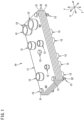
- FIG. 1 is a perspective view of a refrigerant flow path module according to a first embodiment of the present disclosure.
- FIG. 2 is a plan view of the refrigerant flow path module.
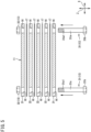
- FIG. 3 is a front view of the refrigerant flow path module.
- a refrigerant flow path module 10 is applied to, for example, an air conditioner including a refrigerant circuit that carries out a vapor compression refrigeration cycle operation.
- Devices such as a four-way switching valve, an electromagnetic valve, a compressor, an accumulator, and an oil separator that constitute the refrigerant circuit are connected to the refrigerant flow path module 10.
- the refrigerant flow path module 10 includes a module body 11, a coupling pipe (refrigerant pipe) 12, and a fastening member 13.
- the module body 11 includes a flow path 15 (see FIGs. 2 and 3 ) through which a refrigerant flows inside.
- the module body 11 includes a plurality of plates 21 and 22.
- the plurality of plates 21 and 22 is stacked and joined to each other.
- the plates 21 and 22 adjacent to each other are joined by brazing.
- the module body 11 according to the present embodiment is supported, for example, in a casing of an air conditioner in an orientation in which a plate surface is in a horizontal direction.
- the plates 21 and 22 according to the present embodiment include stainless steel.
- the plates 21 and 22 according to the present embodiment include SUS304L, for example.
- the plates 21 and 22 have rectangular plate surfaces.
- a direction perpendicular to the plate surfaces of the plates 21 and 22 normal direction of the plates 21 and 22
- a direction in which the plurality of plates 21 and 22 is stacked is also referred to as a first direction Z.
- Two directions that are along the plate surfaces of the plates 21 and 22 (directions orthogonal to the first direction Z) and are orthogonal to each other are also referred to as a second direction X and a third direction Y.
- the long sides of the plates 21 and 22 are disposed along the second direction X, and the short sides are disposed along the third direction Y
- the shape of the plate surfaces of the plates 21 and 22 is not limited to a rectangle, and may be a square, a polygon other than a quadrangle, a circle including an ellipse and an oval, or the like.
- the plurality of plates 21 and 22 have rectangular plate surfaces having the same shape.
- the plurality of plates 21 and 22 have the same thickness (length in the first direction Z).
- the plurality of plates 21 and 22 may have different rectangular shapes, for example, lengths of long sides or lengths of short sides, or may have different thicknesses.
- the plurality of plates 21 and 22 include two end plates 21 disposed at both ends in the first direction Z and an intermediate plate 22 disposed between the two end plates 21.
- the refrigerant flow path module 10 according to the present embodiment includes three intermediate plates 22.
- the three intermediate plates 22 are stacked between the end plates 21 at both ends.
- each of the end plates 21 is provided with a first opening 23 for attaching the coupling pipe 12.
- the first opening 23 passes through the end plates 21 in the first direction Z.
- the first opening 23 has a circular shape.
- the intermediate plates 22 are each provided with a second opening 24 constituting the flow path 15 for the refrigerant.
- the second opening 24 passes through the intermediate plates 22 in the first direction Z.
- the second opening 24 is long in the second direction X or the third direction Y, or has a circular shape.
- the shape of the second opening 24 is not limited, and the shape is appropriately set in accordance with a required form of the flow path 15.
- the first opening 23 formed in the end plates 21 is disposed inside the second opening 24 formed in the intermediate plates 22 adjacent to the end plates 21 as viewed in the first direction Z (a direction passing on the sheet of FIG. 2 ).
- the coupling pipe 12 has a substantially cylindrical shape.
- the coupling pipe 12 includes a material containing copper, for example, copper (pure copper) or a copper alloy.
- the coupling pipe 12 is disposed to have an axis parallel to the first direction Z. Therefore, the axis of the coupling pipe 12 is perpendicular to the plate surface of the end plate 21.
- the first coupling pipe 12 has a large diameter portion 12a at one end in an axial direction, a small diameter portion 12b at the other end, and a stepped portion 12c in the middle.
- the large diameter portion 12a and the small diameter portion 12b have a cylindrical shape.
- the diameter of the large diameter portion 12a is larger than the diameter of the small diameter portion 12b.
- the stepped portion 12c has a conical shape such that the diameter gradually decreases from the large diameter portion 12a toward the small diameter portion 12b.
- the small diameter portion 12b of the coupling pipe 12 is inserted into the first opening 23 formed in the end plate 21.
- An outer peripheral surface of the small diameter portion 12b and the inner peripheral surface of the first opening 23 are bonded by brazing.
- the "inner peripheral surface of the first opening 23" refers to a surface constituting the first opening 23 of the end plate 21.
- a refrigerant pipe constituting the refrigerant circuit of the air conditioner is connected to the large diameter portion 12a of the coupling pipe 12.
- a port of a component such as a valve constituting the refrigerant circuit may be directly connected to the large diameter portion 12a of the coupling pipe 12.
- FIG. 4 is an enlarged sectional view illustrating a portion where the plates are fastened by the fastening member.
- the fastening member 13 fastens the plurality of plates 21 and 22 to each other.
- the fastening member 13 includes stainless steel.
- the fastening member 13 includes SUS430, for example.
- the fastening member 13 includes a bolt 31 and a nut 32.
- the bolt 31 is, for example, a hexagonal bolt, and has a shaft 31a and a head 31b.
- the shaft 31a has a columnar shape.
- the head 31b is formed at one end of the shaft 31a in a longitudinal direction.
- An outer peripheral surface of the head 31b has a hexagonal shape.
- a screw groove 31a1 is formed in an outer peripheral surface at an end of the shaft 31a on an opposite side of the head 31b.
- the nut 32 is, for example, a hexagonal nut.
- the nut 32 has a cylindrical shape.
- a screw groove 32a1 is formed in an inner peripheral surface of the nut 32.
- the screw groove 32a1 of the nut 32 can be engaged with the screw groove 31a1 of the bolt 31.
- An insertion hole 16 into which the shaft 31a of the bolt 31 is inserted is formed in the module body 11.
- the insertion hole 16 passes through the plates 21 and 22 of the module body 11 in the first direction Z.
- the nut 32 is attached to a tip of the bolt 31 inserted into the insertion hole 16.
- the plurality of plates 21 and 22 is sandwiched between the head 31b of the bolt 31 and the nut 32, and is fastened so as to approach each other in the first direction Z.
- a plurality of fastening members 13 is attached to the module body 11.
- the plurality of fastening members 13 is attached to a total of five locations including four corners and a substantially central portion of the module body 11.
- the number and position of the fastening members 13 are not limited, and can be appropriately changed.
- the fastening members 13 are not limited to the bolt 31 and the nut 32, and may be any member as long as the plurality of plates 21 and 22 can be fastened to each other.
- the fastening members 13 may be rivets.
- FIG. 5 is an exploded front view of the refrigerant flow path module.
- FIG. 6 is a front view illustrating a state in which a brazing material is set in the fastening member.
- the plurality of plates 21 and 22 constituting the module body 11 is joined by brazing.
- a brazing material containing copper, for example, bronze brazing is used as the brazing material 17 for brazing the plurality of plates 21 and 22 .
- the sheet-shaped brazing material 17 is disposed between the adjacent plates 21 and 22 to be stacked altogether.
- An insertion hole corresponding to the insertion hole 16 is formed in the sheet-shaped brazing material 17.
- the shaft 31a of the bolt 31 is inserted into the insertion hole 16 of the stacked plates 21 and 22 and the brazing material 17 from below, the nut 32 is attached to the screw groove 31a1 at an upper end of the shaft 31a, and the plurality of plates 21 and 22 is fastened by the bolt 31and the nut 32.
- the plates 21 and 22 fastened by the fastening members 13 are put into a brazing furnace and heated. As a result, the brazing material 17 is melted, and the plurality of plates 21 and 22 is joined.
- a brazed portion 17 (denoted by the same reference sign as the brazing material 17) formed by melting the sheet-shaped brazing material 17 is provided between the plurality of plates 21 and 22.
- an appropriate minute gap (for example, 0.05 mm) needs to be formed in order to allow the brazing material 17 to penetrate between the adjacent plates 21 and 22.
- each of the plates 21 and 22 may be warped by press working or the like in a manufacturing process, and the gap between the plates 21 and 22 may be enlarged by the warpage, and there is a possibility that the brazing material 17 is not appropriately penetrate.
- the plurality of plates 21 and 22 is fastened by the fastening member 13 before brazing, warpage generated in each of the plates 21 and 22 can be corrected, and a minute gap suitable for brazing can be formed between the adjacent plates 21 and 22.
- the fastening member 13 has a thermal expansion coefficient smaller than a thermal expansion coefficient of each of the plates 21 and 22.
- the thermal expansion coefficient of the fastening member 13 is from 0.5 times to 0.8 times the thermal expansion coefficient of the plates 21 and 22. Therefore, when the plurality of plates 21 and 22 fastened by the fastening member 13 is heated in the furnace, the plates 21 and 22 thermally expand more than the fastening member 13. As a result, the fastening by the fastening member 13 becomes stronger, and the warpage of the plates 21 and 22 can be further corrected.
- the fastening member 13 engages a screw groove 31a1 formed in the bolt 31 with the screw groove 32a1 formed in the nut 32 to fasten the plates 21 and 22.
- a gap called backlash is formed between the screw groove 31a1 of the bolt 31 and the screw groove 32a1 of the nut 32.
- This gap is a spiral gap communicating with the outside of the refrigerant flow path module 10.
- the present embodiment includes setting a brazing material to enter the gap before brazing to fill the gap formed in the screw grooves 31a1 and 32a1 of the bolt 31 and the nut 32 with the brazing material.
- a linear brazing material 18 is wound around a portion of the screw groove 31a1 of the bolt 31 protruding from the nut 32 to set the brazing material.
- the brazing material 18 enters the gap between the screw groove 31a1 of the bolt 31 and the screw groove 32a1 of the nut 32 by being heated, and fills the gap.
- the brazing material 18 also enters the gap between the shaft 31a of the bolt 31and the insertion hole 16, and fills the gap together with the excess of the sheet-shaped brazing material 17. Therefore, communication of each gap with the outside is suppressed, and infiltration of moisture is suppressed.
- the brazing material 18 only needs to be able to fill at least the gap between the screw grooves 31a1 and 32a1, and this can suppress the infiltration of moisture from the outside.
- FIG. 7 is an enlarged sectional view illustrating a portion where plates are fastened by a fastening member according to a second embodiment.
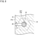
- FIG. 8 is a sectional view taken along line A-A in FIG. 7 .
- each of the plates 21 and 22 of the module body 11 is provided with a groove 26 that opens the insertion hole 16 to outer peripheral edges 21a and 22a of the plates 21 and 22.
- the groove 26 is formed over the entire thickness of each of the plates 21 and 22. As illustrated in FIG. 8 , a width w of the groove 26 is smaller than a diameter of the insertion hole 16. As illustrated in FIG. 7 , the grooves 26 of the plates 21 and 22 communicate with each other in the first direction Z.
- the insertion hole 16 of the module body 11 is largely opened to the outside through the groove 26. Therefore, even if a gap communicating with the outside is formed in the screw grooves 31a1 and 32a1 of the bolt 31 and the nut 32, this gap is largely opened to the outside through the groove 26. Therefore, even if moisture enters the gap between the screw grooves 31a1 and 32a1, the moisture is easily discharged to the outside. It is therefore possible to suppress damage to the fastening member 13 and the plates 21 and 22 due to freezing and expansion of the moisture.
- the groove 26 is not required to be formed in all the plates 21 and 22, and may be formed in some of the plates.
- the groove 26 can be formed only in the end plate 21 closest to the screw grooves 31a1 and 32a1, or in the end plate 21 and the intermediate plate 22 adjacent to the end plate 21. Note that the second embodiment and the configuration in which the brazing material 18 enters the screw grooves 31a1 and 32a1 in the first embodiment can be adopted at the same time.
- FIG. 9 is an enlarged sectional view illustrating a portion where plates are fastened by a fastening member according to a third embodiment.
- each of the plates 21 and 22 of the module body 11 is provided with a hole 27 that opens the insertion hole 16 to outer peripheral edges 21a and 22a of the plates 21 and 22.
- the hole 27 is disposed between one plate surface and the other plate surface of each of the plates 21 and 22 and is closed in the first direction Z. Therefore, the holes 27 of the plates 21 and 22 do not communicate with each other in the first direction Z.
- Other configurations are similar to the configuration of the second embodiment.
- the hole 27 is not required to be formed in all the plates 21 and 22, and may be formed in some of the plates.
- the hole 27 may be formed only in the end plate 21 closest to the screw grooves 31a1 and 32a1, or in the end plate 21 and the intermediate plate 22 adjacent to the end plate 21. Note that the third embodiment and the configuration in which the brazing material 18 enters the screw grooves 31a1 and 32a1 in the first embodiment can be adopted at the same time.
- FIG. 10 is an enlarged sectional view illustrating a portion where plates are fastened by a fastening member according to a fourth embodiment.
- the fastening member 13 includes the bolt 31.
- the screw groove 31a1 of the bolt 31 is engaged with a screw groove 21a1 formed in one end plate (end plate disposed on a lower side in FIG. 10 ) 21. Therefore, in the present embodiment 21, the end plate 21 is also a constituent element of the fastening member 13.
- the brazing material 18 is set in the screw groove 31a1 of the bolt 31 protruding from the end plate 21 as illustrated in FIG. 6 , and the gap between the screw groove 31a1 of the bolt 31 and the screw groove 21a1 of the end plate 21 can be filled with the brazing material.
- Other configurations are similar to the configuration of the first embodiment, and functional effects similar to the functional effects of the first embodiment are obtained.
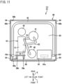
- FIG. 11 is a plan view illustrating an inside of an air conditioner according to an embodiment of the present disclosure.
- FIG. 11 illustrates an outdoor unit 51 of an air conditioner 1.
- the air conditioner 1 is of a separate type and includes an outdoor unit and an indoor unit provided separately from the outdoor unit.
- the outdoor unit 51 is provided with the refrigerant flow path module 10 described above.
- the outdoor unit 51 includes a casing 60 accommodating components such as a compressor 40, an accumulator 41, an outdoor heat exchanger 43, and an oil separator 46 constituting the refrigerant circuit, an electric component unit 61, and the like.
- the casing 60 has a substantially rectangular parallelepiped shape.
- the casing 60 has a bottom plate 63, a support 64, a top panel (not illustrated), a front panel 66, and the like.
- the bottom plate 63 and the top panel have a quadrilateral shape in a top view.
- the support 64 is a long member having a substantially L sectional shape and elongating in an up-down direction, and is attached to each of four corners of the bottom plate 63 and the top panel.
- the casing 60 has a front surface provided with an opening 60a for maintenance.
- the opening 60a is closed by the front panel (front side plate) 66. Detaching the front panel 66 from the casing 60 enables maintenance, replacement, and the like of the components in the casing 60 through the opening 60a.
- the bottom plate 63 of the casing 60 is provided thereon with the components such as the compressor 40, the accumulator 41, the outdoor heat exchanger 43, and the oil separator 46.
- the outdoor heat exchanger 43 is disposed corresponding to (facing) three side surfaces of the casing 60, specifically, a left side surface, a right side surface, and a rear side surface of the casing 60.
- the outdoor heat exchanger 43 has one end provided with a gas header 43e and the other end provided with a liquid header 43f.
- the left side surface, the right side surface, and the rear side surface of the casing 60 are each provided with an intake port 60b for taking in outdoor air.
- the outdoor unit 51 is configured to take in air from the intake port 60b of the casing 60 by driving of a fan (not illustrated), perform heat exchange between the air and the outdoor heat exchanger 43, and then blow out the air upward from an upper part of the casing 60.
- the compressor 40 is disposed at a substantially center in a left-right direction Y near the front surface of the casing 60.
- the electric component unit 61 is disposed near the front surface of the casing 60 and adjacent to a right side of the compressor 40.
- the accumulator 41 is disposed behind the compressor 40.
- An oil separator 46 is disposed on a left side of the accumulator 41.
- the electric component unit 61 includes a controller 61a that controls behavior of the compressor 40, a valve, a fan, and the like.
- the outdoor unit 51 is provided with the refrigerant flow path module 10 as described above.
- the refrigerant flow path module 10 constitutes a part of a flow path of a refrigerant pipe that connects components of a refrigerant circuit such as the compressor 40, the accumulator 41, a flow path switching valve, the outdoor heat exchanger 43, an expansion valve, the oil separator 46, and shutoff valves 39a and 39b.
- the refrigerant flow path module 10 is disposed on the left side (one side in the third direction Y) of the compressor 40 and the accumulator 41.
- the refrigerant flow path module 10 is disposed on a front side (one side in the second direction X) of the oil separator 46.
- the refrigerant flow path module 10 according to the present embodiment is supported in the casing 60 in an orientation in which the plate surfaces of the plates 21 and 22 (see FIG. 1 ) constituting the module body 11 are horizontal.
- the refrigerant flow path module 10 is supported by refrigerant pipes 52 to 55 via the components 39a, 40, 41, and the like of the refrigerant circuit fixed in the casing 60.
- the number of plates constituting the module body is not limited to the above embodiments, and the module body only needs to include at least two plates (the first plate and the second plate).
Landscapes
- Engineering & Computer Science (AREA)
- Mechanical Engineering (AREA)
- Physics & Mathematics (AREA)
- Thermal Sciences (AREA)
- General Engineering & Computer Science (AREA)
- Chemical & Material Sciences (AREA)
- Materials Engineering (AREA)
- Cooling Or The Like Of Semiconductors Or Solid State Devices (AREA)
- Heat-Exchange Devices With Radiators And Conduit Assemblies (AREA)
- Cooling Or The Like Of Electrical Apparatus (AREA)
Abstract
Description
- The present disclosure relates to a method for manufacturing a refrigerant flow path module, a refrigerant flow path module, and an air conditioner.
-
PATENT LITERATURE 1 below discloses a technique of joining a plurality of metal plates. In this technique, a brazing material is attached to a stacking surface of a plurality of metal plates to be stacked and brazed by heating in a furnace.PATENT LITERATURE 1 also discloses forming a dowel that protrudes from a surface on one side of each metal plate and is recessed on a surface on the other side, and caulking and joining by fitting the dowels of the overlapped metal plates to each other. - PATENT LITERATURE 1:
Japanese Laid-Open Patent Publication No. 2008-98484 - In a known refrigeration apparatus including a refrigerant circuit for carrying out a vapor compression refrigeration cycle operation, a plurality of refrigerant pipes through which a refrigerant flows has been integrated into one unit in order to reduce the size of the refrigerant circuit. This unit is manufactured, for example, by overlapping and joining a plurality of plates. It is therefore conceivable to apply the technique described in
PATENT LITERATURE 1 to joining these plates. However, if the plates are warped or the like, a gap between the plates facing each other becomes large, and it becomes difficult for the brazing material to penetrate into the entire space between the plates. It is difficult to reduce the gap between the plates only by fitting with the dowels described inPATENT LITERATURE 1. - An object of the present disclosure is to provide a method for manufacturing a refrigerant flow path module, a refrigerant flow path module, and an air conditioner capable of appropriately joining first and second plates by brazing.
-
- (1) The present disclosure is
- a method for manufacturing a refrigerant flow path module including a first plate and a second plate stacked on each other and including a refrigerant flow path inside, the method including
- arranging a brazing material between the first plate and the second plate,
- fastening the first plate and the second plate between which the brazing material is disposed with a fastening member, and
- heating the first plate and the second plate fastened by the fastening member in a furnace.
In this configuration, by fastening the first and second plates with the fastening member, even if the first plate or the second plate is warped, the gap between the first plate or the second plate can be reduced, and the brazing material can be penetrated between the first and second plates to appropriately join the first and second plates together.
- (2) A thermal expansion coefficient of a material of the fastening member is preferably smaller than a thermal expansion coefficient of a material of the first plate and the second plate.
In this configuration, the thermal expansion of the first and second plates is larger than the thermal expansion of the fastening member when heated in the furnace, and the gap between the first and second plates can be further reduced. - (3) A ratio of the thermal expansion coefficient of the material of the fastening member to the thermal expansion coefficient of the material of the first plate and the second plate is preferably from 0.5 to 0.8.
- (4) The fastening member preferably has a screw groove, and
the method preferably further includes setting a brazing material to enter the screw groove.
In this configuration, when a minute space communicating with the outside is formed in the screw groove of the fastening member, there is a possibility that moisture entering the minute space freezes and expands to damage the refrigerant flow path module. It is therefore possible to suppress formation of a minute space by entering the brazing material into the screw groove in a manufacturing step. - (5) The method preferably further includes forming an insertion hole into which the fastening member is inserted in the first plate and the second plate, and forming a hole or a groove that opens the insertion hole to an outer peripheral edge of the first plate or the second plate in the first plate or the second plate.
When a minute space communicating with the outside is formed between the fastening member and the hole into which the fastening member is inserted, there is a possibility that moisture entering the minute space freezes and expands to damage the refrigerant flow path module. Therefore, by forming the hole or the groove that opens the hole into which the fastening member is inserted to the outer peripheral edge of the first plate or the second plate, it is possible to suppress accumulation of water in the minute space and to suppress damage to the refrigerant flow path module. - (6) A refrigerant flow path module of the present disclosure includes a first plate and a second plate stacked on each other and includes a refrigerant flow path inside, the refrigerant flow path module including
- a brazed portion provided between the first plate and the second plate, and
- a fastening member that fastens the first plate and the second plate.
In this configuration, by fastening the first and second plates with the fastening member, the gap between the first plate or the second plate can be reduced, and the brazing material can spread between the first and second plates to appropriately join the first and second plates together.
- (7) An insertion hole into which the fastening member is inserted is preferably formed in the first plate and the second plate, and
a hole or a groove that opens the insertion hole to an outer peripheral edge of the first plate or the second plate is preferably formed in the first plate or the second plate.
When a minute space communicating with the outside is formed between the fastening member and the hole into which the fastening member is inserted, there is a possibility that moisture entering the minute space freezes and expands to damage the refrigerant flow path module. Therefore, by forming the hole or the groove that opens the hole into which the fastening member is inserted to the outer peripheral edge of the first plate or the second plate, it is possible to suppress accumulation of water in the minute space and to suppress damage to the refrigerant flow path module. - (8) An air conditioner of the present disclosure includes the refrigerant flow path module according to (6) or (7).
-
-
FIG. 1 is a perspective view of a refrigerant flow path module according to a first embodiment of the present disclosure. -
FIG. 2 is a plan view of the refrigerant flow path module. -
FIG. 3 is a front view of the refrigerant flow path module. -
FIG. 4 is an enlarged sectional view illustrating a portion where plates are fastened by a fastening member. -
FIG. 5 is an exploded front view of the refrigerant flow path module. -
FIG. 6 is a front view illustrating a state in which a brazing material is set in the fastening member. -
FIG. 7 is an enlarged sectional view illustrating a portion where plates are fastened by a fastening member according to a second embodiment. -
FIG. 8 is a sectional view taken along line A-A ofFIG. 7 . -
FIG. 9 is an enlarged sectional view illustrating a portion where plates are fastened by a fastening member according to a third embodiment. -
FIG. 10 is an enlarged sectional view illustrating a portion where plates are fastened by a fastening member according to a fourth embodiment. -
FIG. 11 is a plan view illustrating an inside of an air conditioner according to an embodiment of the present disclosure. - Embodiments of the present disclosure will be described in detail hereinafter with reference to the accompanying drawings.
-
FIG. 1 is a perspective view of a refrigerant flow path module according to a first embodiment of the present disclosure.FIG. 2 is a plan view of the refrigerant flow path module.FIG. 3 is a front view of the refrigerant flow path module. - A refrigerant
flow path module 10 according to the present embodiment is applied to, for example, an air conditioner including a refrigerant circuit that carries out a vapor compression refrigeration cycle operation. Devices such as a four-way switching valve, an electromagnetic valve, a compressor, an accumulator, and an oil separator that constitute the refrigerant circuit are connected to the refrigerantflow path module 10. - The refrigerant
flow path module 10 includes amodule body 11, a coupling pipe (refrigerant pipe) 12, and afastening member 13. Themodule body 11 includes a flow path 15 (seeFIGs. 2 and3 ) through which a refrigerant flows inside. Themodule body 11 includes a plurality ofplates plates plates module body 11 according to the present embodiment is supported, for example, in a casing of an air conditioner in an orientation in which a plate surface is in a horizontal direction. - The
plates plates plates plates 21 and 22 (normal direction of theplates 21 and 22), in other words, a direction in which the plurality ofplates plates 21 and 22 (directions orthogonal to the first direction Z) and are orthogonal to each other are also referred to as a second direction X and a third direction Y. In the present embodiment, the long sides of theplates plates - The plurality of
plates plates plates - The plurality of
plates end plates 21 disposed at both ends in the first direction Z and anintermediate plate 22 disposed between the twoend plates 21. The refrigerantflow path module 10 according to the present embodiment includes threeintermediate plates 22. The threeintermediate plates 22 are stacked between theend plates 21 at both ends. - As illustrated in
FIGs. 2 and3 , each of theend plates 21 is provided with afirst opening 23 for attaching thecoupling pipe 12. Thefirst opening 23 passes through theend plates 21 in the first direction Z. Thefirst opening 23 has a circular shape. - The
intermediate plates 22 are each provided with asecond opening 24 constituting theflow path 15 for the refrigerant. Thesecond opening 24 passes through theintermediate plates 22 in the first direction Z. Thesecond opening 24 is long in the second direction X or the third direction Y, or has a circular shape. The shape of thesecond opening 24 is not limited, and the shape is appropriately set in accordance with a required form of theflow path 15. - As illustrated in
FIG. 2 , thefirst opening 23 formed in theend plates 21 is disposed inside thesecond opening 24 formed in theintermediate plates 22 adjacent to theend plates 21 as viewed in the first direction Z (a direction passing on the sheet ofFIG. 2 ). - The
coupling pipe 12 has a substantially cylindrical shape. Thecoupling pipe 12 includes a material containing copper, for example, copper (pure copper) or a copper alloy. Thecoupling pipe 12 is disposed to have an axis parallel to the first direction Z. Therefore, the axis of thecoupling pipe 12 is perpendicular to the plate surface of theend plate 21. - As illustrated in
FIG. 3 , thefirst coupling pipe 12 has alarge diameter portion 12a at one end in an axial direction, asmall diameter portion 12b at the other end, and a steppedportion 12c in the middle. Thelarge diameter portion 12a and thesmall diameter portion 12b have a cylindrical shape. The diameter of thelarge diameter portion 12a is larger than the diameter of thesmall diameter portion 12b. The steppedportion 12c has a conical shape such that the diameter gradually decreases from thelarge diameter portion 12a toward thesmall diameter portion 12b. Thesmall diameter portion 12b of thecoupling pipe 12 is inserted into thefirst opening 23 formed in theend plate 21. An outer peripheral surface of thesmall diameter portion 12b and the inner peripheral surface of thefirst opening 23 are bonded by brazing. The "inner peripheral surface of thefirst opening 23" refers to a surface constituting thefirst opening 23 of theend plate 21. - For example, a refrigerant pipe constituting the refrigerant circuit of the air conditioner is connected to the
large diameter portion 12a of thecoupling pipe 12. A port of a component such as a valve constituting the refrigerant circuit may be directly connected to thelarge diameter portion 12a of thecoupling pipe 12. -
FIG. 4 is an enlarged sectional view illustrating a portion where the plates are fastened by the fastening member. - The
fastening member 13 fastens the plurality ofplates fastening member 13 includes stainless steel. Thefastening member 13 includes SUS430, for example. Thefastening member 13 includes abolt 31 and anut 32. Thebolt 31 is, for example, a hexagonal bolt, and has ashaft 31a and ahead 31b. Theshaft 31a has a columnar shape. Thehead 31b is formed at one end of theshaft 31a in a longitudinal direction. An outer peripheral surface of thehead 31b has a hexagonal shape. A screw groove 31a1 is formed in an outer peripheral surface at an end of theshaft 31a on an opposite side of thehead 31b. - The
nut 32 is, for example, a hexagonal nut. Thenut 32 has a cylindrical shape. A screw groove 32a1 is formed in an inner peripheral surface of thenut 32. The screw groove 32a1 of thenut 32 can be engaged with the screw groove 31a1 of thebolt 31. - An
insertion hole 16 into which theshaft 31a of thebolt 31 is inserted is formed in themodule body 11. Theinsertion hole 16 passes through theplates module body 11 in the first direction Z. Thenut 32 is attached to a tip of thebolt 31 inserted into theinsertion hole 16. By engaging the screw groove 31a1 of thebolt 31 with the screw groove 32a1 of thenut 32, thebolt 31 and thenut 32 are coupled to each other. The plurality ofplates bolt 31 and thenut 32, and is fastened so as to approach each other in the first direction Z. - In the present embodiment, as illustrated in
FIG. 2 , a plurality offastening members 13 is attached to themodule body 11. The plurality offastening members 13 is attached to a total of five locations including four corners and a substantially central portion of themodule body 11. However, the number and position of thefastening members 13 are not limited, and can be appropriately changed. Thefastening members 13 are not limited to thebolt 31 and thenut 32, and may be any member as long as the plurality ofplates fastening members 13 may be rivets. -
FIG. 5 is an exploded front view of the refrigerant flow path module.FIG. 6 is a front view illustrating a state in which a brazing material is set in the fastening member. - The plurality of
plates module body 11 is joined by brazing. As thebrazing material 17 for brazing the plurality ofplates flow path module 10, first, the sheet-shapedbrazing material 17 is disposed between theadjacent plates insertion hole 16 is formed in the sheet-shapedbrazing material 17. Thereafter, theshaft 31a of thebolt 31 is inserted into theinsertion hole 16 of thestacked plates brazing material 17 from below, thenut 32 is attached to the screw groove 31a1 at an upper end of theshaft 31a, and the plurality ofplates nut 32. Thereafter, theplates fastening members 13 are put into a brazing furnace and heated. As a result, thebrazing material 17 is melted, and the plurality ofplates FIG. 4 , a brazed portion 17 (denoted by the same reference sign as the brazing material 17) formed by melting the sheet-shapedbrazing material 17 is provided between the plurality ofplates - When the
adjacent plates brazing material 17 to penetrate between theadjacent plates plates plates brazing material 17 is not appropriately penetrate. In the present embodiment, since the plurality ofplates fastening member 13 before brazing, warpage generated in each of theplates adjacent plates - The
fastening member 13 has a thermal expansion coefficient smaller than a thermal expansion coefficient of each of theplates fastening member 13 is from 0.5 times to 0.8 times the thermal expansion coefficient of theplates plates fastening member 13 is heated in the furnace, theplates member 13. As a result, the fastening by thefastening member 13 becomes stronger, and the warpage of theplates - The
fastening member 13 engages a screw groove 31a1 formed in thebolt 31 with the screw groove 32a1 formed in thenut 32 to fasten theplates bolt 31 and the screw groove 32a1 of thenut 32. This gap is a spiral gap communicating with the outside of the refrigerantflow path module 10. When moisture enters such a gap from the outside, there is a possibility that the moisture freezes and expands in an environment with a low outside air temperature to damage thefastening member 13 and theplates - Similarly, there is a gap between the fastening
member 13 and theinsertion hole 16 of themodule body 11, and there is a possibility that this gap communicates with the outside via the gap between the screw grooves 31a1 and 32a1 described above. An excess of the sheet-like brazing material 17 between theplates member 13 and theinsertion hole 16, but not completely fills the gap. Therefore, moisture enters between the fasteningmember 13 and theinsertion hole 16, and there is a possibility that the moisture freezes and expands in an environment with a low outside air temperature to damage thefastening member 13 and theplates - In order to solve the above disadvantage, the present embodiment includes setting a brazing material to enter the gap before brazing to fill the gap formed in the screw grooves 31a1 and 32a1 of the
bolt 31 and thenut 32 with the brazing material. Specifically, as illustrated inFIG. 6 , alinear brazing material 18 is wound around a portion of the screw groove 31a1 of thebolt 31 protruding from thenut 32 to set the brazing material. Thebrazing material 18 enters the gap between the screw groove 31a1 of thebolt 31 and the screw groove 32a1 of thenut 32 by being heated, and fills the gap. Thebrazing material 18 also enters the gap between theshaft 31a of the bolt 31and theinsertion hole 16, and fills the gap together with the excess of the sheet-shapedbrazing material 17. Therefore, communication of each gap with the outside is suppressed, and infiltration of moisture is suppressed. Thebrazing material 18 only needs to be able to fill at least the gap between the screw grooves 31a1 and 32a1, and this can suppress the infiltration of moisture from the outside. -
FIG. 7 is an enlarged sectional view illustrating a portion where plates are fastened by a fastening member according to a second embodiment.FIG. 8 is a sectional view taken along line A-A inFIG. 7 . - In the second embodiment, each of the
plates module body 11 is provided with agroove 26 that opens theinsertion hole 16 to outerperipheral edges plates groove 26 is formed over the entire thickness of each of theplates FIG. 8 , a width w of thegroove 26 is smaller than a diameter of theinsertion hole 16. As illustrated inFIG. 7 , thegrooves 26 of theplates - As illustrated in
FIG. 7 , theinsertion hole 16 of themodule body 11 is largely opened to the outside through thegroove 26. Therefore, even if a gap communicating with the outside is formed in the screw grooves 31a1 and 32a1 of thebolt 31 and thenut 32, this gap is largely opened to the outside through thegroove 26. Therefore, even if moisture enters the gap between the screw grooves 31a1 and 32a1, the moisture is easily discharged to the outside. It is therefore possible to suppress damage to thefastening member 13 and theplates - The
groove 26 is not required to be formed in all theplates groove 26 can be formed only in theend plate 21 closest to the screw grooves 31a1 and 32a1, or in theend plate 21 and theintermediate plate 22 adjacent to theend plate 21. Note that the second embodiment and the configuration in which thebrazing material 18 enters the screw grooves 31a1 and 32a1 in the first embodiment can be adopted at the same time. -
FIG. 9 is an enlarged sectional view illustrating a portion where plates are fastened by a fastening member according to a third embodiment. - In the third embodiment, each of the
plates module body 11 is provided with ahole 27 that opens theinsertion hole 16 to outerperipheral edges plates hole 27 is disposed between one plate surface and the other plate surface of each of theplates holes 27 of theplates - In the present embodiment, as in the second embodiment, even if a gap communicating with the outside is formed in the screw grooves 31a1 and 32a1 of the
bolt 31 and thenut 32, this gap is largely opened to the outside through thehole 27. Therefore, even if moisture enters the gap between the screw grooves 31a1 and 32a1, the moisture is easily discharged to the outside. It is therefore possible to suppress damage to thefastening member 13 and theplates - The
hole 27 is not required to be formed in all theplates hole 27 may be formed only in theend plate 21 closest to the screw grooves 31a1 and 32a1, or in theend plate 21 and theintermediate plate 22 adjacent to theend plate 21. Note that the third embodiment and the configuration in which thebrazing material 18 enters the screw grooves 31a1 and 32a1 in the first embodiment can be adopted at the same time. -
FIG. 10 is an enlarged sectional view illustrating a portion where plates are fastened by a fastening member according to a fourth embodiment. - In the fourth embodiment, the
fastening member 13 includes thebolt 31. The screw groove 31a1 of thebolt 31 is engaged with a screw groove 21a1 formed in one end plate (end plate disposed on a lower side inFIG. 10 ) 21. Therefore, in thepresent embodiment 21, theend plate 21 is also a constituent element of thefastening member 13. When the refrigerantflow path module 10 according to the present embodiment is brazed, thebrazing material 18 is set in the screw groove 31a1 of thebolt 31 protruding from theend plate 21 as illustrated inFIG. 6 , and the gap between the screw groove 31a1 of thebolt 31 and the screw groove 21a1 of theend plate 21 can be filled with the brazing material. Other configurations are similar to the configuration of the first embodiment, and functional effects similar to the functional effects of the first embodiment are obtained. -
FIG. 11 is a plan view illustrating an inside of an air conditioner according to an embodiment of the present disclosure. -
FIG. 11 illustrates anoutdoor unit 51 of anair conditioner 1. Theair conditioner 1 is of a separate type and includes an outdoor unit and an indoor unit provided separately from the outdoor unit. Theoutdoor unit 51 is provided with the refrigerantflow path module 10 described above. - As illustrated in
FIG. 11 , theoutdoor unit 51 includes acasing 60 accommodating components such as acompressor 40, anaccumulator 41, anoutdoor heat exchanger 43, and anoil separator 46 constituting the refrigerant circuit, anelectric component unit 61, and the like. Thecasing 60 has a substantially rectangular parallelepiped shape. Thecasing 60 has abottom plate 63, asupport 64, a top panel (not illustrated), afront panel 66, and the like. Thebottom plate 63 and the top panel have a quadrilateral shape in a top view. Thesupport 64 is a long member having a substantially L sectional shape and elongating in an up-down direction, and is attached to each of four corners of thebottom plate 63 and the top panel. - The
casing 60 has a front surface provided with anopening 60a for maintenance. Theopening 60a is closed by the front panel (front side plate) 66. Detaching thefront panel 66 from thecasing 60 enables maintenance, replacement, and the like of the components in thecasing 60 through theopening 60a. - The
bottom plate 63 of thecasing 60 is provided thereon with the components such as thecompressor 40, theaccumulator 41, theoutdoor heat exchanger 43, and theoil separator 46. Theoutdoor heat exchanger 43 is disposed corresponding to (facing) three side surfaces of thecasing 60, specifically, a left side surface, a right side surface, and a rear side surface of thecasing 60. Theoutdoor heat exchanger 43 has one end provided with agas header 43e and the other end provided with aliquid header 43f. The left side surface, the right side surface, and the rear side surface of thecasing 60 are each provided with anintake port 60b for taking in outdoor air. - The
outdoor unit 51 is configured to take in air from theintake port 60b of thecasing 60 by driving of a fan (not illustrated), perform heat exchange between the air and theoutdoor heat exchanger 43, and then blow out the air upward from an upper part of thecasing 60. - The
compressor 40 is disposed at a substantially center in a left-right direction Y near the front surface of thecasing 60. Theelectric component unit 61 is disposed near the front surface of thecasing 60 and adjacent to a right side of thecompressor 40. Theaccumulator 41 is disposed behind thecompressor 40. Anoil separator 46 is disposed on a left side of theaccumulator 41. Theelectric component unit 61 includes acontroller 61a that controls behavior of thecompressor 40, a valve, a fan, and the like. - The
outdoor unit 51 is provided with the refrigerantflow path module 10 as described above. The refrigerantflow path module 10 constitutes a part of a flow path of a refrigerant pipe that connects components of a refrigerant circuit such as thecompressor 40, theaccumulator 41, a flow path switching valve, theoutdoor heat exchanger 43, an expansion valve, theoil separator 46, andshutoff valves - The refrigerant
flow path module 10 is disposed on the left side (one side in the third direction Y) of thecompressor 40 and theaccumulator 41. The refrigerantflow path module 10 is disposed on a front side (one side in the second direction X) of theoil separator 46. The refrigerantflow path module 10 according to the present embodiment is supported in thecasing 60 in an orientation in which the plate surfaces of theplates 21 and 22 (seeFIG. 1 ) constituting themodule body 11 are horizontal. For example, the refrigerantflow path module 10 is supported byrefrigerant pipes 52 to 55 via thecomponents casing 60. -
- (1) The refrigerant
flow path module 10 according to the above embodiment includes a first plate (for example, the end plate 21) and a second plate (for example, the intermediate plate 22) stacked on each other, and includes therefrigerant flow path 15 inside. A method for manufacturing the refrigerantflow path module 10 includes arranging thebrazing material 17 between thefirst plate 21 and thesecond plate 22, fastening thefirst plate 21 and thesecond plate 22 between which thebrazing material 17 is disposed with thefastening member 13, and heating thefirst plate 21 and thesecond plate 22 fastened by thefastening member 13 in a furnace. In this manner, by fastening the first andsecond plates fastening member 13, even if thefirst plate 21 or thesecond plate 22 is warped, the gap between thefirst plate 21 or thesecond plate 22 can be reduced, and thebrazing material 17 can be penetrated between the first andsecond plates second plates
The first plate may be either theend plate 21 or theintermediate plate 22, and the second plate may be either theend plate 21 or theintermediate plate 22. - (2) In the above embodiment, the thermal expansion coefficient of the material of the
fastening member 13 is smaller than the thermal expansion coefficient of the material of thefirst plate 21 and thesecond plate 22. Specifically, in the above embodiment, a ratio of the thermal expansion coefficient of the material of thefastening member 13 to the thermal expansion coefficient of the material of thefirst plate 21 and thesecond plate 22 is from 0.5 to 0.8. Therefore, the thermal expansion of the first andsecond plates fastening member 13 when heated in the furnace, and the gap between the first andsecond plates - (3) In the above embodiment, the
fastening member 13 has the screw grooves 31a1, 32a1, and 21a1, and the method for manufacturing the refrigerantflow path module 10 further includes setting thebrazing material 18 to enter the screw grooves 31a1, 32a1, and 21a1. When a minute space communicating with the outside is formed in the portions of the screw grooves 3 1a1,32a1, and 21a1 of thefastening member 13, there is a possibility that the moisture entering the minute space freezes and expands to damage thefastening member 13 and the first andsecond plates brazing material 18 into the screw grooves 31a1,32a1, and 21a1 in a manufacturing step. - (4) The above embodiment further includes forming the
insertion hole 16 into which thefastening member 13 is inserted in thefirst plate 21 and thesecond plate 22, and forming thehole 27 or thegroove 26 that opens theinsertion hole 16 to the outerperipheral edge first plate 21 or thesecond plate 22 in thefirst plate 21 or thesecond plate 22. When a minute space communicating with the outside is formed between the fasteningmember 13 and theinsertion hole 16 into which thefastening member 13 is inserted, there is a possibility that moisture entering the minute space freezes and expands to damage the refrigerantflow path module 10. Therefore, by forming thehole 27 or thegroove 26 that opens theinsertion hole 16 into which thefastening member 13 is inserted to the outerperipheral edge first plate 21 or thesecond plate 22, it is possible to suppress accumulation of water in the minute space and to suppress damage to the refrigerantflow path module 10. - (5) The refrigerant
flow path module 10 according to the above embodiment includes a first plate (for example, the end plate 21) and a second plate (for example, the intermediate plate 22) stacked on each other, and includes therefrigerant flow path 15 inside. The refrigerantflow path module 10 includes the brazed portion 17 (formed by melting the sheet-shaped brazing material 17) provided between thefirst plate 21 and thesecond plate 22, and afastening member 13 that fastens thefirst plate 21 and thesecond plate 22. In this manner, by fastening the first andsecond plates fastening member 13, the warpage generated in thefirst plate 21 and thesecond plate 22 is corrected, the gap between thefirst plate 21 or thesecond plate 22 can be reduced, and thebrazing material 17 can be penetrated between the first andsecond plates second plates - (6) In the above embodiment, the
insertion hole 16 into which thefastening member 13 is inserted is formed in thefirst plate 21 and thesecond plate 22, and thehole 27 or thegroove 26 that opens theinsertion hole 16 to the outerperipheral edge first plate 21 or thesecond plate 22 is formed in thefirst plate 21 or thesecond plate 22. When a minute space communicating with the outside is formed between the fasteningmember 13 and theinsertion hole 16 into which thefastening member 13 is inserted, there is a possibility that moisture entering the minute space freezes and expands to damage the refrigerant flow path module. Therefore, by forming thehole 27 or thegroove 26 that opens theinsertion hole 16 into which thefastening member 13 is inserted to the outerperipheral edge first plate 21 or thesecond plate 22, it is possible to suppress accumulation of water in the minute space and to suppress damage to the refrigerant flow path module. - The present disclosure should not be limited to the above exemplification, but is intended to include any modification recited in the claims within meanings and a scope equivalent to those of the claims.
- For example, the number of plates constituting the module body is not limited to the above embodiments, and the module body only needs to include at least two plates (the first plate and the second plate).
-
- 10
- refrigerant flow path module
- 13
- fastening member
- 15
- flow path
- 16
- insertion hole
- 17
- brazing material
- 18
- brazing material
- 21
- end plate
- 21a
- outer peripheral edge
- 21a1
- screw groove
- 22
- intermediate plate
- 22a
- outer peripheral edge
- 26
- groove
- 27
- hole
- 31a1
- screw groove
- 32a1
- screw groove
Claims (8)
- A method for manufacturing a refrigerant flow path module (10) including a first plate (21 or 22) and a second plate (21 or 22) stacked on each other and including a refrigerant flow path (15) inside, the method comprising:arranging a brazing material (17) between the first plate (21 or 22) and the second plate (21 or 22);fastening the first plate (21 or 22) and the second plate (21 or 22) between which the brazing material (17) is disposed with a fastening member (13); andheating the first plate (21 or 22) and the second plate (21 or 22) fastened by the fastening member (13) in a furnace.
- The method for manufacturing a refrigerant flow path module according to claim 1, wherein a thermal expansion coefficient of a material of the fastening member (13) is smaller than a thermal expansion coefficient of a material of the first plate (21 or 22) and the second plate (21 or 22).
- The method for manufacturing a refrigerant flow path module according to claim 2, wherein a ratio of the thermal expansion coefficient of the material of the fastening member (13) to the thermal expansion coefficient of the material of the first plate (21 or 22) and the second plate (21 or 22) is from 0.5 to 0.8.
- The method for manufacturing a refrigerant flow path module according to any one of claims 1 to 3, whereinthe fastening member (13) has a screw groove (31a1, 32a1), andthe method further includes setting a brazing material (18) to enter the screw groove (31a1, 32a1).
- The method for manufacturing a refrigerant flow path module according to any one of claims 1 to 4, further comprising:forming an insertion hole (16) into which the fastening member (13) is inserted in the first plate (21 or 22) and the second plate (21 or 22); andforming, in the first plate (21 or 22) or the second plate (21 or 22), a groove (26) or a hole (27) that opens the insertion hole (16) to an outer peripheral edge (21a, 22a) of the first plate (21 or 22) or the second plate (21 or 22).
- A refrigerant flow path module including a first plate (21 or 22) and a second plate (21 or 22) stacked on each other and including a refrigerant flow path (15) inside, the refrigerant flow path module comprising:a brazed portion (17) provided between the first plate (21 or 22) and the second plate (21 or 22); anda fastening member (13) that fastens the first plate (21 or 22) and the second plate (21 or 22).
- The refrigerant flow path module according to claim 6, whereinthe first plate (21 or 22) and the second plate (21 or 22) is provided with an insertion hole (16) into which the fastening member (13) is inserted; andthe first plate (21 or 22) or the second plate (21 or 22) is provided with a groove (26) or a hole (27) that opens the insertion hole (16) to an outer peripheral edge (21a, 22a) of the first plate (21 or 22) or the second plate (21 or 22).
- An air conditioner comprising the refrigerant flow path module according to claim 6 or 7.
Applications Claiming Priority (2)
| Application Number | Priority Date | Filing Date | Title |
|---|---|---|---|
| JP2022020289A JP7328585B1 (en) | 2022-02-14 | 2022-02-14 | Refrigerant channel module manufacturing method, coolant channel module, and air conditioner |
| PCT/JP2023/004832 WO2023153515A1 (en) | 2022-02-14 | 2023-02-13 | Method for producing refrigerant channel module, refrigerant channel module, and air conditioner |
Publications (2)
| Publication Number | Publication Date |
|---|---|
| EP4480615A1 true EP4480615A1 (en) | 2024-12-25 |
| EP4480615A4 EP4480615A4 (en) | 2025-07-16 |
Family
ID=87563079
Family Applications (1)
| Application Number | Title | Priority Date | Filing Date |
|---|---|---|---|
| EP23752977.1A Pending EP4480615A4 (en) | 2022-02-14 | 2023-02-13 | METHOD FOR MANUFACTURING A REFRIGERANT DUCT MODULE, REFRIGERANT DUCT MODULE AND AIR CONDITIONING SYSTEM |
Country Status (5)
| Country | Link |
|---|---|
| US (1) | US20240384903A1 (en) |
| EP (1) | EP4480615A4 (en) |
| JP (1) | JP7328585B1 (en) |
| CN (1) | CN118679021A (en) |
| WO (1) | WO2023153515A1 (en) |
Families Citing this family (1)
| Publication number | Priority date | Publication date | Assignee | Title |
|---|---|---|---|---|
| CN117283073A (en) * | 2023-09-22 | 2023-12-26 | 鹰普流体科技(镇江)有限公司 | A brazing process for multi-layer complex internal flow channel hydraulic components |
Family Cites Families (15)
| Publication number | Priority date | Publication date | Assignee | Title |
|---|---|---|---|---|
| JPS57103335U (en) * | 1980-12-17 | 1982-06-25 | ||
| JP2832896B2 (en) * | 1990-02-27 | 1998-12-09 | スズキ株式会社 | Motorcycle engine unit |
| EP0959330B1 (en) * | 1990-08-20 | 2006-01-18 | Oval Corporation | Positive displacement flowmeter and method of producing the same |
| US5450997A (en) * | 1993-06-28 | 1995-09-19 | Ford Motor Company | Brazing fixture for heat exchanger |
| JPH08267128A (en) * | 1995-03-30 | 1996-10-15 | Katayama Kogyo Kk | Multi-layer spiral tube for automobile and its manufacture |
| JPH0979616A (en) * | 1995-09-19 | 1997-03-28 | Hitachi Ltd | Air conditioner |
| JP3753794B2 (en) * | 1996-07-08 | 2006-03-08 | 昭和電工株式会社 | Aluminum material for vacuum brazing and drone cup type heat exchanger using the material and excellent in corrosion resistance |
| JP3935711B2 (en) * | 2001-11-20 | 2007-06-27 | 株式会社日本クライメイトシステムズ | Manufacturing method of heat exchanger |
| JP2006125830A (en) * | 2004-09-28 | 2006-05-18 | Tokyo Roki Co Ltd | Heat exchanger for internal combustion engine and mounting structure thereof |
| DE102005030438A1 (en) * | 2005-06-30 | 2007-01-04 | Behr Gmbh & Co. Kg | Clamping device for soldering a multi-part metal unit of especially a heat exchanger is made of a material with lower thermal expansion coefficient and is placed round metal parts in soldering furnace |
| JP2008098484A (en) | 2006-10-13 | 2008-04-24 | Fine Steel Engineering:Kk | Integrated laminate manufacturing method and machine part |
| KR101446956B1 (en) * | 2012-12-13 | 2014-11-04 | 대한칼소닉주식회사 | Battery heat sink having structure stacked fluid path |
| KR20180015503A (en) * | 2016-08-03 | 2018-02-13 | 한국원자력연구원 | Heat exchanger and nuclear power plant having the same |
| JP6785409B2 (en) * | 2016-10-21 | 2020-11-18 | パナソニックIpマネジメント株式会社 | Heat exchanger and refrigeration system using it |
| KR101976543B1 (en) * | 2018-06-25 | 2019-05-09 | 한국원자력연구원 | Heat exchanger and nuclear power plant having the same |
-
2022
- 2022-02-14 JP JP2022020289A patent/JP7328585B1/en active Active
-
2023
- 2023-02-13 WO PCT/JP2023/004832 patent/WO2023153515A1/en not_active Ceased
- 2023-02-13 EP EP23752977.1A patent/EP4480615A4/en active Pending
- 2023-02-13 CN CN202380020787.5A patent/CN118679021A/en active Pending
-
2024
- 2024-07-29 US US18/786,647 patent/US20240384903A1/en active Pending
Also Published As
| Publication number | Publication date |
|---|---|
| CN118679021A (en) | 2024-09-20 |
| EP4480615A4 (en) | 2025-07-16 |
| WO2023153515A1 (en) | 2023-08-17 |
| US20240384903A1 (en) | 2024-11-21 |
| JP2023117624A (en) | 2023-08-24 |
| JP7328585B1 (en) | 2023-08-17 |
Similar Documents
| Publication | Publication Date | Title |
|---|---|---|
| CN203785332U (en) | Laminated headers, heat exchangers and air conditioning units | |
| AU2005326711B2 (en) | Parallel flow heat exchangers incorporating porous inserts | |
| CN105164491B (en) | Laminated header, heat exchanger, and air conditioner | |
| EP3060868B1 (en) | Heat exchanger and side plate | |
| US6267176B1 (en) | Weld-free heat exchanger assembly | |
| CN109564067B (en) | Heat exchanger and refrigeration system using the same | |
| US20240384903A1 (en) | Method for manufacturing refrigerant flow path module, refrigerant flow path module, and air conditioner | |
| JP6711317B2 (en) | Heat exchanger | |
| EP2998680A1 (en) | Laminated header, heat exchanger, and air conditioner | |
| US20080023183A1 (en) | Heat exchanger assembly | |
| JP7118279B2 (en) | HEAT EXCHANGER, MANUFACTURING METHOD THEREOF, AND AIR CONDITIONER | |
| EP3553448B1 (en) | Secondarily applied cold side features for cast heat exchanger | |
| CN206817863U (en) | refrigerator | |
| WO2022208733A1 (en) | Heat exchanger | |
| EP4481303A1 (en) | Refrigerant flow path module and air conditioner | |
| JP7545066B2 (en) | Refrigeration cycle device and manufacturing method for refrigeration cycle device | |
| EP4308870B1 (en) | Microchannel heat exchanger for appliance condenser | |
| US20220316812A1 (en) | Heat exchanger, heat exchange unit, refrigeration cycle apparatus, and method for manufacturing heat exchange member | |
| JP7455290B1 (en) | Heat exchangers and air conditioners | |
| EP4080150A1 (en) | Heat exchanger, heat exchanger unit, and refrigeration cycle device | |
| JP2024051391A (en) | Manufacturing method of refrigerant flow path module and assembly jig | |
| WO2025069935A1 (en) | Heat exchanger unit, air conditioning indoor unit, refrigeration cycle device, and method for manufacturing heat exchanger unit | |
| CN118776207A (en) | Thermal Improvement of VIS Refrigerator |
Legal Events
| Date | Code | Title | Description |
|---|---|---|---|
| STAA | Information on the status of an ep patent application or granted ep patent |
Free format text: STATUS: THE INTERNATIONAL PUBLICATION HAS BEEN MADE |
|
| PUAI | Public reference made under article 153(3) epc to a published international application that has entered the european phase |
Free format text: ORIGINAL CODE: 0009012 |
|
| STAA | Information on the status of an ep patent application or granted ep patent |
Free format text: STATUS: REQUEST FOR EXAMINATION WAS MADE |
|
| 17P | Request for examination filed |
Effective date: 20240808 |
|
| AK | Designated contracting states |
Kind code of ref document: A1 Designated state(s): AL AT BE BG CH CY CZ DE DK EE ES FI FR GB GR HR HU IE IS IT LI LT LU LV MC ME MK MT NL NO PL PT RO RS SE SI SK SM TR |
|
| DAV | Request for validation of the european patent (deleted) | ||
| DAX | Request for extension of the european patent (deleted) | ||
| A4 | Supplementary search report drawn up and despatched |
Effective date: 20250618 |
|
| RIC1 | Information provided on ipc code assigned before grant |
Ipc: B23K 1/00 20060101AFI20250612BHEP Ipc: B23K 3/00 20060101ALI20250612BHEP Ipc: F28D 9/00 20060101ALI20250612BHEP Ipc: F25B 41/42 20210101ALI20250612BHEP Ipc: B23K 1/008 20060101ALI20250612BHEP Ipc: B23K 1/19 20060101ALI20250612BHEP Ipc: B23K 1/20 20060101ALI20250612BHEP Ipc: B23K 101/14 20060101ALN20250612BHEP |
|
| P01 | Opt-out of the competence of the unified patent court (upc) registered |
Free format text: CASE NUMBER: UPC_APP_3800_4480615/2025 Effective date: 20250820 |
|
| GRAP | Despatch of communication of intention to grant a patent |
Free format text: ORIGINAL CODE: EPIDOSNIGR1 |
|
| STAA | Information on the status of an ep patent application or granted ep patent |
Free format text: STATUS: GRANT OF PATENT IS INTENDED |
|
| RIC1 | Information provided on ipc code assigned before grant |
Ipc: B23K 1/00 20060101AFI20260102BHEP Ipc: B23K 3/00 20060101ALI20260102BHEP Ipc: F28D 9/00 20060101ALI20260102BHEP Ipc: F25B 41/42 20210101ALI20260102BHEP Ipc: B23K 1/008 20060101ALI20260102BHEP Ipc: B23K 1/19 20060101ALI20260102BHEP Ipc: B23K 1/20 20060101ALI20260102BHEP Ipc: B23K 101/14 20060101ALN20260102BHEP |
|
| RIC1 | Information provided on ipc code assigned before grant |
Ipc: B23K 1/00 20060101AFI20260121BHEP Ipc: B23K 3/00 20060101ALI20260121BHEP Ipc: F28D 9/00 20060101ALI20260121BHEP Ipc: F25B 41/42 20210101ALI20260121BHEP Ipc: B23K 1/008 20060101ALI20260121BHEP Ipc: B23K 1/19 20060101ALI20260121BHEP Ipc: B23K 1/20 20060101ALI20260121BHEP Ipc: B23K 101/14 20060101ALN20260121BHEP |
|
| INTG | Intention to grant announced |
Effective date: 20260206 |
|
| RIC1 | Information provided on ipc code assigned before grant |
Ipc: B23K 1/00 20060101AFI20260202BHEP Ipc: B23K 3/00 20060101ALI20260202BHEP Ipc: F28D 9/00 20060101ALI20260202BHEP Ipc: F25B 41/42 20210101ALI20260202BHEP Ipc: B23K 1/008 20060101ALI20260202BHEP Ipc: B23K 1/19 20060101ALI20260202BHEP Ipc: B23K 1/20 20060101ALI20260202BHEP Ipc: B23K 101/14 20060101ALN20260202BHEP |
|
| GRAJ | Information related to disapproval of communication of intention to grant by the applicant or resumption of examination proceedings by the epo deleted |
Free format text: ORIGINAL CODE: EPIDOSDIGR1 |
|
| STAA | Information on the status of an ep patent application or granted ep patent |
Free format text: STATUS: REQUEST FOR EXAMINATION WAS MADE |
|
| GRAP | Despatch of communication of intention to grant a patent |
Free format text: ORIGINAL CODE: EPIDOSNIGR1 |
|
| STAA | Information on the status of an ep patent application or granted ep patent |
Free format text: STATUS: GRANT OF PATENT IS INTENDED |
|
| INTC | Intention to grant announced (deleted) |