EP4480601A1 - Tundish and continuous casting method using same - Google Patents
Tundish and continuous casting method using same Download PDFInfo
- Publication number
- EP4480601A1 EP4480601A1 EP23795948.1A EP23795948A EP4480601A1 EP 4480601 A1 EP4480601 A1 EP 4480601A1 EP 23795948 A EP23795948 A EP 23795948A EP 4480601 A1 EP4480601 A1 EP 4480601A1
- Authority
- EP
- European Patent Office
- Prior art keywords
- tundish
- molten steel
- weir
- inlet pipe
- gas inlet
- Prior art date
- Legal status (The legal status is an assumption and is not a legal conclusion. Google has not performed a legal analysis and makes no representation as to the accuracy of the status listed.)
- Pending
Links
Images

Classifications
-
- B—PERFORMING OPERATIONS; TRANSPORTING
- B22—CASTING; POWDER METALLURGY
- B22D—CASTING OF METALS; CASTING OF OTHER SUBSTANCES BY THE SAME PROCESSES OR DEVICES
- B22D41/00—Casting melt-holding vessels, e.g. ladles, tundishes, cups or the like
- B22D41/003—Casting melt-holding vessels, e.g. ladles, tundishes, cups or the like with impact pads
-
- B—PERFORMING OPERATIONS; TRANSPORTING
- B22—CASTING; POWDER METALLURGY
- B22D—CASTING OF METALS; CASTING OF OTHER SUBSTANCES BY THE SAME PROCESSES OR DEVICES
- B22D41/00—Casting melt-holding vessels, e.g. ladles, tundishes, cups or the like
- B22D41/08—Casting melt-holding vessels, e.g. ladles, tundishes, cups or the like for bottom pouring
-
- B—PERFORMING OPERATIONS; TRANSPORTING
- B22—CASTING; POWDER METALLURGY
- B22D—CASTING OF METALS; CASTING OF OTHER SUBSTANCES BY THE SAME PROCESSES OR DEVICES
- B22D1/00—Treatment of fused masses in the ladle or the supply runners before casting
- B22D1/002—Treatment with gases
- B22D1/005—Injection assemblies therefor
-
- B—PERFORMING OPERATIONS; TRANSPORTING
- B22—CASTING; POWDER METALLURGY
- B22D—CASTING OF METALS; CASTING OF OTHER SUBSTANCES BY THE SAME PROCESSES OR DEVICES
- B22D11/00—Continuous casting of metals, i.e. casting in indefinite lengths
- B22D11/10—Supplying or treating molten metal
- B22D11/103—Distributing the molten metal, e.g. using runners, floats, distributors
-
- B—PERFORMING OPERATIONS; TRANSPORTING
- B22—CASTING; POWDER METALLURGY
- B22D—CASTING OF METALS; CASTING OF OTHER SUBSTANCES BY THE SAME PROCESSES OR DEVICES
- B22D11/00—Continuous casting of metals, i.e. casting in indefinite lengths
- B22D11/10—Supplying or treating molten metal
- B22D11/11—Treating the molten metal
- B22D11/116—Refining the metal
- B22D11/117—Refining the metal by treating with gases
-
- B—PERFORMING OPERATIONS; TRANSPORTING
- B22—CASTING; POWDER METALLURGY
- B22D—CASTING OF METALS; CASTING OF OTHER SUBSTANCES BY THE SAME PROCESSES OR DEVICES
- B22D11/00—Continuous casting of metals, i.e. casting in indefinite lengths
- B22D11/10—Supplying or treating molten metal
- B22D11/11—Treating the molten metal
- B22D11/116—Refining the metal
- B22D11/118—Refining the metal by circulating the metal under, over or around weirs
-
- B—PERFORMING OPERATIONS; TRANSPORTING
- B22—CASTING; POWDER METALLURGY
- B22D—CASTING OF METALS; CASTING OF OTHER SUBSTANCES BY THE SAME PROCESSES OR DEVICES
- B22D41/00—Casting melt-holding vessels, e.g. ladles, tundishes, cups or the like
-
- B—PERFORMING OPERATIONS; TRANSPORTING
- B22—CASTING; POWDER METALLURGY
- B22D—CASTING OF METALS; CASTING OF OTHER SUBSTANCES BY THE SAME PROCESSES OR DEVICES
- B22D43/00—Mechanical cleaning, e.g. skimming of molten metals
Definitions
- the present invention relates to a tundish for supplying molten metal poured from a ladle therein to a casting mold in a continuous casting step and capable of efficiently removing non-metallic inclusions in the molten metal poured into the tundish, and a continuous casting method using such a tundish.
- Non-metallic inclusions such as Al 2 O 3 , which is a deoxidation product, in molten steel may cause defects after a rolling process.
- a tundish is used to float and separate such non-metallic inclusions that flow out with the molten steel when it is tapped from a ladle. The higher the floatation separation rate of the non-metallic inclusions, the higher the cleanliness of the molten steel that can be produced.
- Patent Literature 1 discloses a technology for promoting the effect of floating inclusions, using a method for producing clean steel including providing a tundish with a perforated weir extending from the bottom of the tundish to a position above the surface of molten metal and thus dividing the tundish into a steel-receiving region for receiving molten steel from a ladle and a near-stationary steel region including an outlet port for directing the molten steel to a casting mold, and immersing a pouring nozzle from the ladle in the molten steel in the steel-receiving region to supply the molten steel.
- Patent Literature 2 discloses a technology for, to a tundish divided into a steel-receiving side and an outlet port side by a perforated weir in contact with the bottom wall of the tundish and having holes, providing a lower weir with an open upper portion, on the outlet port side of the perforated weir, and optimizing the shape of the tundish, the positions of the weirs, and the shapes and positions of the holes.
- Patent Literature 3 discloses a technology for enhancing the effect of floating inclusions by providing a weir including flowing holes between a pouring position for receiving molten steel from a ladle and an outlet port to a casting mold, and blowing a predetermined amount of an inert gas into the molten steel from the bottom of the tundish on the outlet port side of the weir.
- Patent Literature 2 after inclusions in molten steel pass through the perforated weir, the floatation of the inclusions is promoted by the lower weir. However, the effect of floating the inclusions is insufficient. Further, since molten steel remains on the steel-receiving side of the lower weir after the completion of a casting process, the costs of residual steel may increase.
- Patent Literature 3 increases the effect of floating inclusions by blowing an inert gas into molten steel.
- the proportion of the gas volume in the molten steel is increased, only a small effect of floating the inclusions can be obtained.
- the gas flow rate is increased, the surface of the molten steel will fluctuate when bubbles burst.
- the molten steel may be contaminated due to the entrapment of tundish slag, which remains on the surface of the molten steel.
- the present invention is made in view of the above circumstances, and the object thereof is to provide a tundish capable of efficiently and inexpensively promoting the floatation of inclusions contained in molten steel poured into the tundish from a ladle, and a continuous casting method using such a tundish.
- a tundish according to the present invention for solving the above problems includes a weir provided between a molten steel pouring portion in which a flow of molten steel poured from a ladle collides with a bottom of the tundish and a molten steel outlet port through which the molten steel flows from the tundish to a casting mold.
- the weir includes a wall portion surrounding the molten steel pouring portion from all sides and extending upward from the bottom of the tundish, and a hood-shaped portion provided at an upper end of the wall portion and protruding in a horizontal direction while facing the molten steel pouring portion.
- the weir includes one or more notches continuous from the wall portion to the hood-shaped portion, and includes a refractory bottom surrounded by the wall portion and including a first porous portion, and also includes a first gas inlet pipe connected to the first porous portion within the weir and within the refractory including the first porous portion.
- the tundish further optionally includes a bottom refractory provided with a second porous portion and with a second gas inlet pipe connected to the second porous portion, at the bottom of the tundish between the weir and the molten steel outlet port.
- the tundish according to the present invention may further include, as a more preferable solution means, a precast refractory installed on a wall portion of the tundish and including a third gas inlet pipe connected to the first gas inlet pipe or the second gas inlet pipe or extending from the first gas inlet pipe or the second gas inlet pipe.
- a precast refractory installed on a wall portion of the tundish and including a third gas inlet pipe connected to the first gas inlet pipe or the second gas inlet pipe or extending from the first gas inlet pipe or the second gas inlet pipe.
- a continuous casting method is a method for producing a cast steel slab by continuous casting, including using the above tundish and pouring molten steel from the tundish into a casting mold while blowing an inert gas into the molten steel from the first porous portion through the first gas inlet pipe at a flow rate R1 of the inert gas per unit area of a bottom of the weir controlled in a range of 0.02 to 1.0 NL/(s ⁇ m 2 ).
- the continuous casting method according to the present invention may further include, as a more preferable solution means, blowing an inert gas into the molten steel from the second porous portion through the second gas inlet pipe at a flow rate R2 of the inert gas per unit area of the second porous portion controlled in a range of 0.1 to 10 NL/(s ⁇ m 2 ).
- the tundish according to the present invention it is possible to suppress a short-circuit flow of molten steel, which has been poured from a ladle, around the bottom of the tundish and to change a flow of the molten steel to the upward direction, thereby promoting the floatation separation of inclusions. It is also possible to promote the floatation separation of inclusions with the rise of air bubbles from a porous portion of a weir.
- the tundish according to the present invention can further promote the floatation separation of inclusions by air bubbles blown into the molten steel through a porous portion provided in a bottom refractory between the weir and a molten steel outlet port, before the molten steel flows out to a casting mold, which is preferable.
- the tundish according to the present invention further includes a precast refractory having a gas inlet pipe therein and installed on a wall portion of the tundish, thereby enabling easy installation of an apparatus for blowing a gas into molten steel from a porous portion provided at the bottom of the weir or the bottom of the tundish. This can reduce obstructions to the operation due to failures in the installation, and thus can avoid risks, such as the leakage of steel, which is preferable from a safety perspective.
- the tundish is used, and the amount of an inert gas blown from the bottom of the weir or the bottom of the tundish is controlled to be in an appropriate range. This is sufficient for floatation separation of inclusions and can also suppress the entrapment of slag in the molten steel from the surface of the molten steel in the tundish. Thus, highly cleanliness steel can be easily produced.
- Figs. 1 schematically show a tundish according to an embodiment of the present invention.
- Fig. 1(a) is a cross-sectional view along line A-A
- Fig. 1(b) is a cross-sectional view along line B-B
- Fig. 1(c) is a cross-sectional view along line C-C.
- a tundish 1 of this embodiment is an intermediate vessel used in continuous casting of steel for pouring molten steel in a ladle into a casting mold for continuous casting.
- the tundish 1 is a vessel that is substantially in the form of a rectangular parallelepiped with an open upper face, for example.
- the tundish 1 is supplied with molten steel from a ladle (not shown) through a pouring nozzle 2.
- the stored molten steel is supplied into respective casting molds (not shown) through two molten steel outlet ports 3 provided at the bottom.
- a weir 4 is provided between a molten steel pouring portion 2a, in which a flow of molten steel poured from the ladle collides with a bottom 1a of the tundish, and the molten steel outlet port 3, through which the molten steel flows from the tundish 1.
- the weir 4 includes a wall portion 4a surrounding the molten steel pouring portion 2a from all sides and extending upward from the bottom 1a of the tundish, and a hood-shaped portion 4b that is provided at an upper end of the wall portion 4a and protrudes in a horizontal direction while facing the molten steel pouring portion 2a.
- the weir 4 has one or more notches continuous from the wall portion 4a to the hood-shaped portion 4b.
- the weir 4 has a refractory bottom 4c surrounded by the wall portion 4a and including a first porous portion 4d, and has a first gas inlet pipe 5a connected to the first porous portion 4d within the weir and within the refractory including the first porous portion 4d.
- the first porous portion 4d preferably accounts for 15% or more of the entire area of the refractory bottom 4c surrounded by the wall portion 4a of the weir 4.
- the first porous portion 4d is preferably not provided around the point of collision of the molten steel poured from the ladle.
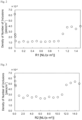
- Fig. 2 is a graph illustrating the influence of the flow rate R1 [NL/(s ⁇ m 2 )] of an inert gas per unit area of the bottom of the weir 4 on the number of inclusions that flow out to a cast steel slab.
- the number of inclusions flowing out to the cast steel slab the number of inclusions with a size of 10 ⁇ m or larger in the slab was evaluated by taking five samples from the two largest faces of a slab in the shape of a rectangular parallelepiped, and polishing the plane to be observed of each sample, and then determining the number of inclusions per unit area by microscopic observation. As can be seen from Fig.
- the flow rate R1 of the inert gas per unit area of the bottom of the weir 4 needs to be controlled to be in the range of 0.02 to 1.0 NL/(s ⁇ m 2 ).
- the flow rate R1 of the inert gas is in the range of 0.02 to 0.2 NL/(s ⁇ m 2 ).
- a precast refractory 6 that is installed on the wall portion of the tundish 1 and includes a third gas inlet pipe 5c connected to or extending from the first gas inlet pipe 5a provided in the weir 4. This makes it easier to install a refractory to the tundish and thus can reduce obstructions to the operation due to failures in the installation.
- a refractory 7 which includes a second porous portion 7a and a second gas inlet pipe 5b connected to the second porous portion 7a, at the bottom 1a of the tundish at a position between the weir 4 and the molten steel outlet port 3.
- a precast refractory 6 that is installed on the wall portion of the tundish 1 and includes a third gas inlet pipe 5c connected to or extending from the second gas inlet pipe 5b.
- the refractory 7 and the precast refractory 6 may be integrally formed.
- the refractory 7 is preferably installed across the entire bottom 1a of the tundish in a direction orthogonal to a flow of molten steel, which has been poured from the ladle, toward the molten steel outlet port 3 to the casting mold. This can generate a flow toward the surface of the tundish as with a lower weir, and thus can promote the floatation separation of inclusions. Besides, as shown in Fig. 1 , it is also possible to provide an upper weir 8 on the upstream side of the position where the refractory 7 having the second porous portion 7a is provided, that is, on the side for receiving steel from the ladle. This can prevent the inclusions floating on the steel-receiving side from flowing to the side for pouring the steel into the casting mold.
- Fig. 3 is a graph illustrating the relationship between the flow rate R2 [NL/(s ⁇ m 2 )] of an inert gas per unit area of the second porous portion 7a of the refractory 7 and the density of the number of inclusions in a slab.
- R2 flow rate
- Fig. 3 tests were conducted without blowing an inert gas into molten steel through the first porous portion 4d provided in the weir 4.
- the evaluation of inclusions was conducted in a manner similar to the above.
- R2 is less than 0.1 NL/(s ⁇ m 2 )
- the effect of floating inclusions in the tundish is small, which is unfavorable.
- the flow rate R2 of the inert gas per unit area of the second porous portion 7a is preferably controlled to be in the range of 0.1 to 10 NL/(s ⁇ m 2 ).
- Integrally forming the refractory 7 including the second porous portion 7a with the precast refractory 6 installed on the wall portion of the tundish 1 can reduce the time required to perform maintenance on the tundish, which is preferable.
- Each of the first porous portion 4d and the second porous portion 7a can be prepared by using as aggregate spherical particles containing alumina as a main component, and baking them at 1600°C or higher.
- the average pore size of each of the first porous portion 4d and the second porous portion 7a is preferably 20 to 120 ⁇ m.
- the average pore size can be determined using mercury porosimetry and so on in accordance with JIS R 1655:2003, for example. Setting the average pore size to such a range can control the size of air bubbles blown into molten steel to be in a predetermined range, which is effective in suppressing the inclusion of slag in the molten steel.
- Three hundred tons of molten steel prepared by blowing oxygen in a converter and performing a vacuum degassing process in an RH vacuum degassing apparatus was stored in a ladle. Then, a continuous casting process was performed by pouring the molten steel from the ladle into a casting mold through the tundish 1 shown in Fig. 1 .
- the flow rate R1 [NL/(s ⁇ m 2 )] of an inert gas per unit area of the bottom of the weir 4, as well as the flow rate R2 [NL/(s ⁇ m 2 )] of an inert gas per unit area of the second porous portion 7a of the refractory 7 disposed between the weir 4 and the outlet port 3 was adjusted under the conditions shown in Table 1.
- the density of the number of inclusions in the slab after each process was inspected in a manner similar to the above.
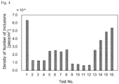
- Fig. 4 shows a graph of the results. Table 1 No.
- Test No. 1 is a conventional example in which R1 and R2 were each set to zero.
- Test Nos. 2 to 4 are invention examples in which an appropriate amount of an inert gas was blown into the molten steel only from the first porous portion 4d at the bottom of the weir 4.
- Test Nos. 5 to 8 are reference examples in which an appropriate amount of an inert gas was blown only from the second porous portion 7a provided at the bottom of the tundish between the weir 4 and the outlet port 3.
- Test Nos. 9 to 12 are invention examples in which both the above examples were combined and an appropriate amount of an inert gas was blown into the molten steel. Test Nos.
- symbol “L” that is the unit of a volume means 10 -3 m 3
- symbol “N” used for the volume of a gas represents the volume in the standard state, that is, at a temperature of 0°C and a pressure of 101325 Pa.
Landscapes
- Engineering & Computer Science (AREA)
- Mechanical Engineering (AREA)
- Continuous Casting (AREA)
- Treatment Of Steel In Its Molten State (AREA)
Abstract
Description
- The present invention relates to a tundish for supplying molten metal poured from a ladle therein to a casting mold in a continuous casting step and capable of efficiently removing non-metallic inclusions in the molten metal poured into the tundish, and a continuous casting method using such a tundish.
- To produce high-quality steel materials, there is a need for further improvement in the technology for higher cleanliness of molten steel. Non-metallic inclusions such as Al2O3, which is a deoxidation product, in molten steel may cause defects after a rolling process. Thus, such non-metallic inclusions need to be separated and removed as much as possible prior to a casting process. A tundish is used to float and separate such non-metallic inclusions that flow out with the molten steel when it is tapped from a ladle. The higher the floatation separation rate of the non-metallic inclusions, the higher the cleanliness of the molten steel that can be produced.
- Methods have been proposed for efficiently floating and separating inclusions in a tundish. For example,
Patent Literature 1 discloses a technology for promoting the effect of floating inclusions, using a method for producing clean steel including providing a tundish with a perforated weir extending from the bottom of the tundish to a position above the surface of molten metal and thus dividing the tundish into a steel-receiving region for receiving molten steel from a ladle and a near-stationary steel region including an outlet port for directing the molten steel to a casting mold, and immersing a pouring nozzle from the ladle in the molten steel in the steel-receiving region to supply the molten steel. -
Patent Literature 2 discloses a technology for, to a tundish divided into a steel-receiving side and an outlet port side by a perforated weir in contact with the bottom wall of the tundish and having holes, providing a lower weir with an open upper portion, on the outlet port side of the perforated weir, and optimizing the shape of the tundish, the positions of the weirs, and the shapes and positions of the holes. -
Patent Literature 3 discloses a technology for enhancing the effect of floating inclusions by providing a weir including flowing holes between a pouring position for receiving molten steel from a ladle and an outlet port to a casting mold, and blowing a predetermined amount of an inert gas into the molten steel from the bottom of the tundish on the outlet port side of the weir. -
- Patent Literature 1:
JP-S53-6231 - Patent Literature 2:
JP-H10-216909 -
Patent Literature 3JP-2011-143449 - However, the above conventional technologies have the following problems.
- In the technology described in
Patent Literature 1, holes for taking out the residual steel are provided in the perforated weir on the bottom side of the tundish. It is therefore concerned, after inclusions in the molten steel pass through a region around the bottom of the perforated weir, the inclusions may flow out due to a short-circuit flow that is flowing around the bottom of the tundish toward the outlet port for the molten steel. - In the technology of
Patent Literature 2, after inclusions in molten steel pass through the perforated weir, the floatation of the inclusions is promoted by the lower weir. However, the effect of floating the inclusions is insufficient. Further, since molten steel remains on the steel-receiving side of the lower weir after the completion of a casting process, the costs of residual steel may increase. - The technology of
Patent Literature 3 increases the effect of floating inclusions by blowing an inert gas into molten steel. However, unless the proportion of the gas volume in the molten steel is increased, only a small effect of floating the inclusions can be obtained. In contrast, if the gas flow rate is increased, the surface of the molten steel will fluctuate when bubbles burst. Thus, there is a concern that the molten steel may be contaminated due to the entrapment of tundish slag, which remains on the surface of the molten steel. - The present invention is made in view of the above circumstances, and the object thereof is to provide a tundish capable of efficiently and inexpensively promoting the floatation of inclusions contained in molten steel poured into the tundish from a ladle, and a continuous casting method using such a tundish.
- A tundish according to the present invention for solving the above problems includes a weir provided between a molten steel pouring portion in which a flow of molten steel poured from a ladle collides with a bottom of the tundish and a molten steel outlet port through which the molten steel flows from the tundish to a casting mold. The weir includes a wall portion surrounding the molten steel pouring portion from all sides and extending upward from the bottom of the tundish, and a hood-shaped portion provided at an upper end of the wall portion and protruding in a horizontal direction while facing the molten steel pouring portion. The weir includes one or more notches continuous from the wall portion to the hood-shaped portion, and includes a refractory bottom surrounded by the wall portion and including a first porous portion, and also includes a first gas inlet pipe connected to the first porous portion within the weir and within the refractory including the first porous portion. The tundish further optionally includes a bottom refractory provided with a second porous portion and with a second gas inlet pipe connected to the second porous portion, at the bottom of the tundish between the weir and the molten steel outlet port.
- Note that the tundish according to the present invention may further include, as a more preferable solution means, a precast refractory installed on a wall portion of the tundish and including a third gas inlet pipe connected to the first gas inlet pipe or the second gas inlet pipe or extending from the first gas inlet pipe or the second gas inlet pipe.
- A continuous casting method according to the present invention is a method for producing a cast steel slab by continuous casting, including using the above tundish and pouring molten steel from the tundish into a casting mold while blowing an inert gas into the molten steel from the first porous portion through the first gas inlet pipe at a flow rate R1 of the inert gas per unit area of a bottom of the weir controlled in a range of 0.02 to 1.0 NL/(s·m2).
- Note that the continuous casting method according to the present invention may further include, as a more preferable solution means, blowing an inert gas into the molten steel from the second porous portion through the second gas inlet pipe at a flow rate R2 of the inert gas per unit area of the second porous portion controlled in a range of 0.1 to 10 NL/(s·m2).
- With the tundish according to the present invention, it is possible to suppress a short-circuit flow of molten steel, which has been poured from a ladle, around the bottom of the tundish and to change a flow of the molten steel to the upward direction, thereby promoting the floatation separation of inclusions. It is also possible to promote the floatation separation of inclusions with the rise of air bubbles from a porous portion of a weir.
- In addition, the tundish according to the present invention can further promote the floatation separation of inclusions by air bubbles blown into the molten steel through a porous portion provided in a bottom refractory between the weir and a molten steel outlet port, before the molten steel flows out to a casting mold, which is preferable.
- The tundish according to the present invention further includes a precast refractory having a gas inlet pipe therein and installed on a wall portion of the tundish, thereby enabling easy installation of an apparatus for blowing a gas into molten steel from a porous portion provided at the bottom of the weir or the bottom of the tundish. This can reduce obstructions to the operation due to failures in the installation, and thus can avoid risks, such as the leakage of steel, which is preferable from a safety perspective.
- In the continuous casting method according to the present invention, the tundish is used, and the amount of an inert gas blown from the bottom of the weir or the bottom of the tundish is controlled to be in an appropriate range. This is sufficient for floatation separation of inclusions and can also suppress the entrapment of slag in the molten steel from the surface of the molten steel in the tundish. Thus, highly cleanliness steel can be easily produced.
-
- [
Figs. 1 ] are schematic cross-sectional views of a tundish according to an embodiment of the present invention in which (a) is a cross-sectional view along line A-A, (b) is a cross-sectional view along line B-B, and (c) is a cross-sectional view along line C-C. - [
Fig. 2 ] is a graph illustrating the influence of the flow rate R1 of an inert gas per unit area of the bottom of a weir on the number of inclusions that flow out to a cast steel slab. - [
Fig. 3 ] is a graph illustrating the influence of the flow rate R2 of an inert gas per unit area of a porous portion of a refractory provided at the bottom of a tundish on the number of inclusions that flow out to a cast steel slab. - [
Fig. 4 ] is a graph illustrating the number of inclusions that flow out to each cast steel slab obtained by casting under the gas blowing conditions shown in Table 1. - An embodiment of the present invention will be specifically described. Note that the drawings are only schematic, and thus may differ from the actual ones. In addition, the following embodiment only illustrates examples of an apparatus and a method for embodying the technical idea of the present invention. Thus, the configuration of the present invention is not limited thereto. That is, the technical idea of the present invention can be modified in various ways within the technical scope recited in the claims.
-
Figs. 1 schematically show a tundish according to an embodiment of the present invention.Fig. 1(a) is a cross-sectional view along line A-A,Fig. 1(b) is a cross-sectional view along line B-B, andFig. 1(c) is a cross-sectional view along line C-C. A tundish 1 of this embodiment is an intermediate vessel used in continuous casting of steel for pouring molten steel in a ladle into a casting mold for continuous casting. The tundish 1 is a vessel that is substantially in the form of a rectangular parallelepiped with an open upper face, for example. The tundish 1 is supplied with molten steel from a ladle (not shown) through apouring nozzle 2. In the example shown inFig. 1 , the stored molten steel is supplied into respective casting molds (not shown) through two moltensteel outlet ports 3 provided at the bottom. - In this embodiment, a
weir 4 is provided between a moltensteel pouring portion 2a, in which a flow of molten steel poured from the ladle collides with abottom 1a of the tundish, and the moltensteel outlet port 3, through which the molten steel flows from the tundish 1. Theweir 4 includes awall portion 4a surrounding the moltensteel pouring portion 2a from all sides and extending upward from the bottom 1a of the tundish, and a hood-shapedportion 4b that is provided at an upper end of thewall portion 4a and protrudes in a horizontal direction while facing the moltensteel pouring portion 2a. Theweir 4 has one or more notches continuous from thewall portion 4a to the hood-shapedportion 4b. Theweir 4 has arefractory bottom 4c surrounded by thewall portion 4a and including a firstporous portion 4d, and has a firstgas inlet pipe 5a connected to the firstporous portion 4d within the weir and within the refractory including the firstporous portion 4d. The firstporous portion 4d preferably accounts for 15% or more of the entire area of therefractory bottom 4c surrounded by thewall portion 4a of theweir 4. Although the upper limit of the area of the firstporous portion 4d is not defined herein, the firstporous portion 4d is preferably not provided around the point of collision of the molten steel poured from the ladle. - With such a configuration, it is possible to suppress a short-circuit flow of molten steel, which has been poured from the ladle, around the bottom 1a of the tundish and to change a flow of the molten steel to the upward direction, thereby promoting the floatation separation of inclusions. Further, blowing an inert gas from the first
porous portion 4d can allow non-metallic inclusions to be trapped by air bubbles of the inert gas and thus can further promote the floatation separation of the inclusions. By providing the firstporous portion 4d in therefractory bottom 4c of the moltensteel pouring portion 2a, gas bubbles to be separated from the firstporous portion 4d are allowed to become finer due to a shearing force generated by a high-speed pouring flow that has collided with therefractory bottom 4c and been directed in the horizontal direction. Thus, the effect of increasing the probability of trapping the inclusions can be achieved. -
Fig. 2 is a graph illustrating the influence of the flow rate R1 [NL/(s·m2)] of an inert gas per unit area of the bottom of theweir 4 on the number of inclusions that flow out to a cast steel slab. Regarding the number of inclusions flowing out to the cast steel slab, the number of inclusions with a size of 10 µm or larger in the slab was evaluated by taking five samples from the two largest faces of a slab in the shape of a rectangular parallelepiped, and polishing the plane to be observed of each sample, and then determining the number of inclusions per unit area by microscopic observation. As can be seen fromFig. 2 , when R1 is less than 0.02 NL/(s·m2), the effect of floating the inclusions in the tundish is small, which is unfavorable. Meanwhile, when R1 exceeds 1.0 NL/(s·m2), the amount of the gas blown into the molten steel is too large, with the result that a large amount of slag is entrapped in the molten steel in the tundish, which is unfavorable. Therefore, the flow rate R1 of the inert gas per unit area of the bottom of theweir 4 needs to be controlled to be in the range of 0.02 to 1.0 NL/(s·m2). Preferably, the flow rate R1 of the inert gas is in the range of 0.02 to 0.2 NL/(s·m2). - To supply an inert gas to the first
porous portion 4d, it is preferable to provide a precast refractory 6 that is installed on the wall portion of thetundish 1 and includes a thirdgas inlet pipe 5c connected to or extending from the firstgas inlet pipe 5a provided in theweir 4. This makes it easier to install a refractory to the tundish and thus can reduce obstructions to the operation due to failures in the installation. - In this embodiment, it is further preferable to, optionally, provide a refractory 7, which includes a second
porous portion 7a and a secondgas inlet pipe 5b connected to the secondporous portion 7a, at the bottom 1a of the tundish at a position between theweir 4 and the moltensteel outlet port 3. It is preferable to provide a precast refractory 6 that is installed on the wall portion of thetundish 1 and includes a thirdgas inlet pipe 5c connected to or extending from the secondgas inlet pipe 5b. The refractory 7 and the precast refractory 6 may be integrally formed. The refractory 7 is preferably installed across theentire bottom 1a of the tundish in a direction orthogonal to a flow of molten steel, which has been poured from the ladle, toward the moltensteel outlet port 3 to the casting mold. This can generate a flow toward the surface of the tundish as with a lower weir, and thus can promote the floatation separation of inclusions. Besides, as shown inFig. 1 , it is also possible to provide anupper weir 8 on the upstream side of the position where the refractory 7 having the secondporous portion 7a is provided, that is, on the side for receiving steel from the ladle. This can prevent the inclusions floating on the steel-receiving side from flowing to the side for pouring the steel into the casting mold. -
Fig. 3 is a graph illustrating the relationship between the flow rate R2 [NL/(s·m2)] of an inert gas per unit area of the secondporous portion 7a of the refractory 7 and the density of the number of inclusions in a slab. RegardingFig. 3 , tests were conducted without blowing an inert gas into molten steel through the firstporous portion 4d provided in theweir 4. The evaluation of inclusions was conducted in a manner similar to the above. As can be seen fromFig. 3 , when R2 is less than 0.1 NL/(s·m2), the effect of floating inclusions in the tundish is small, which is unfavorable. Meanwhile, when R2 exceeds 10 NL/(s·m2), the amount of the gas blown into the molten steel is too large, with the result that a large amount of slag is entrapped in the molten steel in the tundish, which is unfavorable. Therefore, the flow rate R2 of the inert gas per unit area of the secondporous portion 7a is preferably controlled to be in the range of 0.1 to 10 NL/(s·m2). - Integrally forming the refractory 7 including the second
porous portion 7a with the precast refractory 6 installed on the wall portion of thetundish 1 can reduce the time required to perform maintenance on the tundish, which is preferable. - Each of the first
porous portion 4d and the secondporous portion 7a can be prepared by using as aggregate spherical particles containing alumina as a main component, and baking them at 1600°C or higher. The average pore size of each of the firstporous portion 4d and the secondporous portion 7a is preferably 20 to 120 µm. The average pore size can be determined using mercury porosimetry and so on in accordance with JIS R 1655:2003, for example. Setting the average pore size to such a range can control the size of air bubbles blown into molten steel to be in a predetermined range, which is effective in suppressing the inclusion of slag in the molten steel. - Three hundred tons of molten steel prepared by blowing oxygen in a converter and performing a vacuum degassing process in an RH vacuum degassing apparatus was stored in a ladle. Then, a continuous casting process was performed by pouring the molten steel from the ladle into a casting mold through the
tundish 1 shown inFig. 1 . In thetundish 1, the flow rate R1 [NL/(s·m2)] of an inert gas per unit area of the bottom of theweir 4, as well as the flow rate R2 [NL/(s·m2)] of an inert gas per unit area of the secondporous portion 7a of the refractory 7 disposed between theweir 4 and theoutlet port 3 was adjusted under the conditions shown in Table 1. The density of the number of inclusions in the slab after each process was inspected in a manner similar to the above.Fig. 4 shows a graph of the results.Table 1 No. Gas Flow Rate Density R1 at Bottom of Weir Gas Flow Rate Density R2 at Bottom of TD Remarks NL/(s ·m2) NL/(s ·m2) 1 0 0 Conventional Example 2 0.4 0 Invention Example 3 0.6 0 Invention Example 4 0.8 0 Invention Example 5 0 2 Reference Example 6 0 4 Reference Example 7 0 6 Reference Example 8 0 8 Reference Example 9 0.2 2 Invention Example 10 0.4 2 Invention Example 11 0.6 4 Invention Example 12 0.8 8 Invention Example 13 0.01 0.2 Comparative Example 14 0.01 13 Comparative Example 15 1.2 0.2 Comparative Example 16 1.2 13 Comparative Example - Test No. 1 is a conventional example in which R1 and R2 were each set to zero. Test Nos. 2 to 4 are invention examples in which an appropriate amount of an inert gas was blown into the molten steel only from the first
porous portion 4d at the bottom of theweir 4. Test Nos. 5 to 8 are reference examples in which an appropriate amount of an inert gas was blown only from the secondporous portion 7a provided at the bottom of the tundish between theweir 4 and theoutlet port 3. Test Nos. 9 to 12 are invention examples in which both the above examples were combined and an appropriate amount of an inert gas was blown into the molten steel. Test Nos. 13 to 16 are comparative examples in which the amount of an inert gas blown into the molten steel was outside an appropriate range. From the results inFig. 4 , it is found that, in the invention examples in which an inert gas was blown within an amount in an appropriate range, the cleanliness of the slab is significantly higher than that of the conventional examples and the comparative examples. - In this specification, symbol "L" that is the unit of a volume means 10-3 m3, and symbol "N" used for the volume of a gas represents the volume in the standard state, that is, at a temperature of 0°C and a pressure of 101325 Pa.
-
- 1
- tundish
- 1a
- bottom of tundish
- 2
- pouring nozzle
- 2a
- molten steel pouring portion
- 3
- molten steel outlet port
- 4
- weir
- 4a
- wall portion
- 4b
- hood-shaped portion
- 4c
- refractory bottom
- 4d
- (first) porous portion
- 5a
- (first) gas inlet pipe
- 5b
- (second) gas inlet pipe
- 5c
- (third) gas inlet pipe
- 6
- precast refractory
- 7
- refractory (including porous portion)
- 7a
- (second) porous portion
- 8
- upper weir
Claims (4)
- A tundish comprising a weir provided between a molten steel pouring portion in which a flow of molten steel poured from a ladle collides with a bottom of the tundish and a molten steel outlet port through which the molten steel flows from the tundish to a casting mold, the weir includinga wall portion surrounding the molten steel pouring portion from all sides and extending upward from the bottom of the tundish, anda hood-shaped portion provided at an upper end of the wall portion and protruding in a horizontal direction while facing the molten steel pouring portion,characterized in thatthe weir includes one or more notches continuous from the wall portion to the hood-shaped portion, and includes a refractory bottom surrounded by the wall portion and including a first porous portion, and also includes a first gas inlet pipe connected to the first porous portion within the weir and within the refractory including the first porous portion, andthe tundish further optionally includes a bottom refractory provided with a second porous portion and with a second gas inlet pipe connected to the second porous portion, at the bottom of the tundish between the weir and the molten steel outlet port.
- The tundish according to claim 1, further comprising a precast refractory installed on a wall portion of the tundish and including a third gas inlet pipe connected to the first gas inlet pipe or the second gas inlet pipe or extending from the first gas inlet pipe or the second gas inlet pipe.
- A continuous casting method for producing a cast steel slab, comprising using the tundish according to claim 1 or 2 and pouring molten steel from the tundish into a casting mold while blowing an inert gas into the molten steel from the first porous portion through the first gas inlet pipe at a flow rate R1 of the inert gas per unit area of a bottom of the weir controlled in a range of 0.02 to 1.0 NL/(s·m2) to produce a cast steel slab.
- The continuous casting method according to claim 3, further comprising blowing an inert gas into the molten steel from the second porous portion through the second gas inlet pipe at a flow rate R2 of the inert gas per unit area of the second porous portion controlled in a range of 0.1 to 10 NL/(s·m2).
Applications Claiming Priority (2)
| Application Number | Priority Date | Filing Date | Title |
|---|---|---|---|
| JP2022072127 | 2022-04-26 | ||
| PCT/JP2023/010367 WO2023210201A1 (en) | 2022-04-26 | 2023-03-16 | Tundish and continuous casting method using same |
Publications (2)
| Publication Number | Publication Date |
|---|---|
| EP4480601A1 true EP4480601A1 (en) | 2024-12-25 |
| EP4480601A4 EP4480601A4 (en) | 2025-07-02 |
Family
ID=88518610
Family Applications (1)
| Application Number | Title | Priority Date | Filing Date |
|---|---|---|---|
| EP23795948.1A Pending EP4480601A4 (en) | 2022-04-26 | 2023-03-16 | INTERMEDIATE TANKS AND CONTINUOUS CASTING PROCESSES |
Country Status (6)
| Country | Link |
|---|---|
| US (1) | US20250222515A1 (en) |
| EP (1) | EP4480601A4 (en) |
| JP (1) | JP7711755B2 (en) |
| KR (1) | KR20240167900A (en) |
| CN (1) | CN118922261A (en) |
| WO (1) | WO2023210201A1 (en) |
Family Cites Families (12)
| Publication number | Priority date | Publication date | Assignee | Title |
|---|---|---|---|---|
| JPS536231A (en) | 1976-07-07 | 1978-01-20 | Nippon Kokan Kk | Method of making clean steel |
| JPS54158331A (en) * | 1978-06-05 | 1979-12-14 | Aikoh Co | Tundish for continuous steel casting |
| JP3520640B2 (en) * | 1995-12-15 | 2004-04-19 | Jfeスチール株式会社 | Method for removing nonmetallic inclusions in molten metal |
| JP3563222B2 (en) | 1997-01-31 | 2004-09-08 | 日本冶金工業株式会社 | Tundish for continuous casting of steel |
| CN2863315Y (en) * | 2005-12-01 | 2007-01-31 | 洛阳铁门耐火材料有限公司 | Blowing type turbulence proof controller for bakie |
| JP2011143449A (en) | 2010-01-14 | 2011-07-28 | Jfe Steel Corp | Method for removing inclusion in tundish for continuous casting |
| JP5556465B2 (en) | 2010-07-15 | 2014-07-23 | Jfeスチール株式会社 | Manufacturing method of high cleanliness steel slab by continuous casting |
| CN104364032B (en) * | 2012-06-18 | 2017-02-22 | 杰富意钢铁株式会社 | Method for manufacturing high-purity steel casting, and tundish |
| CN203109191U (en) | 2013-03-15 | 2013-08-07 | 濮阳濮耐高温材料(集团)股份有限公司 | Tundish current stabilizer with air blowing function |
| JP6572658B2 (en) * | 2015-07-28 | 2019-09-11 | 日本製鉄株式会社 | Bubble generating device and bubble generating method in molten metal |
| US11338357B2 (en) | 2019-08-19 | 2022-05-24 | Harbisonwalker International, Inc. | Diffusion article |
| CN113564309B (en) * | 2020-04-28 | 2022-10-21 | 宝山钢铁股份有限公司 | Tundish with function of removing molten steel inclusions by blowing argon |
-
2023
- 2023-03-16 JP JP2023534302A patent/JP7711755B2/en active Active
- 2023-03-16 CN CN202380033072.3A patent/CN118922261A/en active Pending
- 2023-03-16 WO PCT/JP2023/010367 patent/WO2023210201A1/en not_active Ceased
- 2023-03-16 EP EP23795948.1A patent/EP4480601A4/en active Pending
- 2023-03-16 US US18/846,767 patent/US20250222515A1/en active Pending
- 2023-03-16 KR KR1020247036030A patent/KR20240167900A/en active Pending
Also Published As
| Publication number | Publication date |
|---|---|
| JPWO2023210201A1 (en) | 2023-11-02 |
| CN118922261A (en) | 2024-11-08 |
| WO2023210201A1 (en) | 2023-11-02 |
| EP4480601A4 (en) | 2025-07-02 |
| US20250222515A1 (en) | 2025-07-10 |
| JP7711755B2 (en) | 2025-07-23 |
| KR20240167900A (en) | 2024-11-28 |
Similar Documents
| Publication | Publication Date | Title |
|---|---|---|
| CN104364032B (en) | Method for manufacturing high-purity steel casting, and tundish | |
| JP4271551B2 (en) | Continuous casting equipment for high cleanliness steel by tundish | |
| JP5516235B2 (en) | Manufacturing method of high cleanliness steel slab by continuous casting | |
| KR20140129895A (en) | Tundish for continuous casting | |
| US20250222515A1 (en) | Tundish and continuous casting method using same | |
| JP7663809B2 (en) | Continuous casting method for steel | |
| JP5831163B2 (en) | Manufacturing method of high cleanliness steel | |
| JP5751078B2 (en) | Manufacturing method of high cleanliness steel slab by continuous casting | |
| JP2017064778A (en) | Upper nozzle for continuous casting | |
| JP4815821B2 (en) | Continuous casting method of aluminum killed steel | |
| JP5556465B2 (en) | Manufacturing method of high cleanliness steel slab by continuous casting | |
| KR101914084B1 (en) | Molten material processing apparatus | |
| EP4549051A1 (en) | Tundish for continuous casting, steel continuous casting method, and gas supply device | |
| JP2001113347A (en) | Hot water supply device and continuous casting method for steel | |
| EP4545205A1 (en) | Tundish for continuous casting, continuous casting method for steel, and weir | |
| JP3464856B2 (en) | Tundish for continuous casting of high cleanliness steel | |
| EP4667133A1 (en) | Nozzle for continuous casting, continuous casting apparatus, tundish, and continuous casting method | |
| JP5831138B2 (en) | Manufacturing method of high cleanliness steel slab by continuous casting | |
| JP4474948B2 (en) | Steel continuous casting method | |
| JPH10249498A (en) | Method for continuously casting high cleanliness steel with tundish providing field weir closing bottom part | |
| JP2000202602A (en) | Inclusion removal method in tundish for continuous casting | |
| RU2185261C1 (en) | Tundish ladle for continuous casting of steel | |
| JPH024754Y2 (en) | ||
| JP2005262242A (en) | Tundish excellent in floating-up property for inclusion | |
| JPH1034299A (en) | Pouring device |
Legal Events
| Date | Code | Title | Description |
|---|---|---|---|
| STAA | Information on the status of an ep patent application or granted ep patent |
Free format text: STATUS: THE INTERNATIONAL PUBLICATION HAS BEEN MADE |
|
| PUAI | Public reference made under article 153(3) epc to a published international application that has entered the european phase |
Free format text: ORIGINAL CODE: 0009012 |
|
| STAA | Information on the status of an ep patent application or granted ep patent |
Free format text: STATUS: REQUEST FOR EXAMINATION WAS MADE |
|
| 17P | Request for examination filed |
Effective date: 20240918 |
|
| AK | Designated contracting states |
Kind code of ref document: A1 Designated state(s): AL AT BE BG CH CY CZ DE DK EE ES FI FR GB GR HR HU IE IS IT LI LT LU LV MC ME MK MT NL NO PL PT RO RS SE SI SK SM TR |
|
| REG | Reference to a national code |
Ref country code: DE Ref legal event code: R079 Free format text: PREVIOUS MAIN CLASS: B22D0011100000 Ipc: B22D0001000000 |
|
| A4 | Supplementary search report drawn up and despatched |
Effective date: 20250602 |
|
| RIC1 | Information provided on ipc code assigned before grant |
Ipc: B22D 41/08 20060101ALI20250526BHEP Ipc: B22D 41/00 20060101ALI20250526BHEP Ipc: B22D 11/118 20060101ALI20250526BHEP Ipc: B22D 11/117 20060101ALI20250526BHEP Ipc: B22D 11/103 20060101ALI20250526BHEP Ipc: B22D 1/00 20060101AFI20250526BHEP |
|
| DAV | Request for validation of the european patent (deleted) | ||
| DAX | Request for extension of the european patent (deleted) | ||
| STAA | Information on the status of an ep patent application or granted ep patent |
Free format text: STATUS: EXAMINATION IS IN PROGRESS |
|
| 17Q | First examination report despatched |
Effective date: 20250924 |
|
| GRAP | Despatch of communication of intention to grant a patent |
Free format text: ORIGINAL CODE: EPIDOSNIGR1 |
|
| STAA | Information on the status of an ep patent application or granted ep patent |
Free format text: STATUS: GRANT OF PATENT IS INTENDED |
|
| INTG | Intention to grant announced |
Effective date: 20260130 |
|
| RIN1 | Information on inventor provided before grant (corrected) |
Inventor name: FURUMAI, KOHEI Inventor name: ARAMAKI, NORICHIKA |
|
| GRAS | Grant fee paid |
Free format text: ORIGINAL CODE: EPIDOSNIGR3 |
|
| GRAA | (expected) grant |
Free format text: ORIGINAL CODE: 0009210 |
|
| STAA | Information on the status of an ep patent application or granted ep patent |
Free format text: STATUS: THE PATENT HAS BEEN GRANTED |