EP4480591A2 - Durchflusssensor für bodenmarkierungskügelchen - Google Patents
Durchflusssensor für bodenmarkierungskügelchen Download PDFInfo
- Publication number
- EP4480591A2 EP4480591A2 EP24211732.3A EP24211732A EP4480591A2 EP 4480591 A2 EP4480591 A2 EP 4480591A2 EP 24211732 A EP24211732 A EP 24211732A EP 4480591 A2 EP4480591 A2 EP 4480591A2
- Authority
- EP
- European Patent Office
- Prior art keywords
- bead
- flow
- sensor module
- flow sensor
- hopper
- Prior art date
- Legal status (The legal status is an assumption and is not a legal conclusion. Google has not performed a legal analysis and makes no representation as to the accuracy of the status listed.)
- Pending
Links
Images


Classifications
-
- B—PERFORMING OPERATIONS; TRANSPORTING
- B05—SPRAYING OR ATOMISING IN GENERAL; APPLYING FLUENT MATERIALS TO SURFACES, IN GENERAL
- B05B—SPRAYING APPARATUS; ATOMISING APPARATUS; NOZZLES
- B05B12/00—Arrangements for controlling delivery; Arrangements for controlling the spray area
- B05B12/08—Arrangements for controlling delivery; Arrangements for controlling the spray area responsive to condition of liquid or other fluent material to be discharged, of ambient medium or of target ; responsive to condition of spray devices or of supply means, e.g. pipes, pumps or their drive means
- B05B12/085—Arrangements for controlling delivery; Arrangements for controlling the spray area responsive to condition of liquid or other fluent material to be discharged, of ambient medium or of target ; responsive to condition of spray devices or of supply means, e.g. pipes, pumps or their drive means responsive to flow or pressure of liquid or other fluent material to be discharged
-
- B—PERFORMING OPERATIONS; TRANSPORTING
- B05—SPRAYING OR ATOMISING IN GENERAL; APPLYING FLUENT MATERIALS TO SURFACES, IN GENERAL
- B05B—SPRAYING APPARATUS; ATOMISING APPARATUS; NOZZLES
- B05B7/00—Spraying apparatus for discharge of liquids or other fluent materials from two or more sources, e.g. of liquid and air, of powder and gas
- B05B7/14—Spraying apparatus for discharge of liquids or other fluent materials from two or more sources, e.g. of liquid and air, of powder and gas designed for spraying particulate materials
- B05B7/1404—Arrangements for supplying particulate material
-
- B—PERFORMING OPERATIONS; TRANSPORTING
- B05—SPRAYING OR ATOMISING IN GENERAL; APPLYING FLUENT MATERIALS TO SURFACES, IN GENERAL
- B05B—SPRAYING APPARATUS; ATOMISING APPARATUS; NOZZLES
- B05B12/00—Arrangements for controlling delivery; Arrangements for controlling the spray area
- B05B12/004—Arrangements for controlling delivery; Arrangements for controlling the spray area comprising sensors for monitoring the delivery, e.g. by displaying the sensed value or generating an alarm
- B05B12/006—Pressure or flow rate sensors
-
- B—PERFORMING OPERATIONS; TRANSPORTING
- B05—SPRAYING OR ATOMISING IN GENERAL; APPLYING FLUENT MATERIALS TO SURFACES, IN GENERAL
- B05B—SPRAYING APPARATUS; ATOMISING APPARATUS; NOZZLES
- B05B13/00—Machines or plants for applying liquids or other fluent materials to surfaces of objects or other work by spraying, not covered by groups B05B1/00 - B05B11/00
- B05B13/005—Machines or plants for applying liquids or other fluent materials to surfaces of objects or other work by spraying, not covered by groups B05B1/00 - B05B11/00 mounted on vehicles or designed to apply a liquid on a very large surface, e.g. on the road, on the surface of large containers
-
- B—PERFORMING OPERATIONS; TRANSPORTING
- B05—SPRAYING OR ATOMISING IN GENERAL; APPLYING FLUENT MATERIALS TO SURFACES, IN GENERAL
- B05B—SPRAYING APPARATUS; ATOMISING APPARATUS; NOZZLES
- B05B7/00—Spraying apparatus for discharge of liquids or other fluent materials from two or more sources, e.g. of liquid and air, of powder and gas
- B05B7/14—Spraying apparatus for discharge of liquids or other fluent materials from two or more sources, e.g. of liquid and air, of powder and gas designed for spraying particulate materials
- B05B7/1404—Arrangements for supplying particulate material
- B05B7/1413—Apparatus to be carried on or by a person, e.g. by hand; Apparatus comprising a container fixed to the discharge device
- B05B7/1418—Apparatus to be carried on or by a person, e.g. by hand; Apparatus comprising a container fixed to the discharge device comprising means for supplying an additional liquid
-
- B—PERFORMING OPERATIONS; TRANSPORTING
- B05—SPRAYING OR ATOMISING IN GENERAL; APPLYING FLUENT MATERIALS TO SURFACES, IN GENERAL
- B05B—SPRAYING APPARATUS; ATOMISING APPARATUS; NOZZLES
- B05B7/00—Spraying apparatus for discharge of liquids or other fluent materials from two or more sources, e.g. of liquid and air, of powder and gas
- B05B7/14—Spraying apparatus for discharge of liquids or other fluent materials from two or more sources, e.g. of liquid and air, of powder and gas designed for spraying particulate materials
- B05B7/1404—Arrangements for supplying particulate material
- B05B7/1477—Arrangements for supplying particulate material means for supplying to several spray apparatus
-
- B—PERFORMING OPERATIONS; TRANSPORTING
- B05—SPRAYING OR ATOMISING IN GENERAL; APPLYING FLUENT MATERIALS TO SURFACES, IN GENERAL
- B05B—SPRAYING APPARATUS; ATOMISING APPARATUS; NOZZLES
- B05B7/00—Spraying apparatus for discharge of liquids or other fluent materials from two or more sources, e.g. of liquid and air, of powder and gas
- B05B7/16—Spraying apparatus for discharge of liquids or other fluent materials from two or more sources, e.g. of liquid and air, of powder and gas incorporating means for heating or cooling the material to be sprayed
- B05B7/18—Spraying apparatus for discharge of liquids or other fluent materials from two or more sources, e.g. of liquid and air, of powder and gas incorporating means for heating or cooling the material to be sprayed the material having originally the shape of a wire, rod or the like
-
- E—FIXED CONSTRUCTIONS
- E01—CONSTRUCTION OF ROADS, RAILWAYS, OR BRIDGES
- E01C—CONSTRUCTION OF, OR SURFACES FOR, ROADS, SPORTS GROUNDS, OR THE LIKE; MACHINES OR AUXILIARY TOOLS FOR CONSTRUCTION OR REPAIR
- E01C23/00—Auxiliary devices or arrangements for constructing, repairing, reconditioning, or taking-up road or like surfaces
- E01C23/16—Devices for marking-out, applying, or forming traffic or like markings on finished paving; Protecting fresh markings
- E01C23/20—Devices for marking-out, applying, or forming traffic or like markings on finished paving; Protecting fresh markings for forming markings in situ
-
- E—FIXED CONSTRUCTIONS
- E01—CONSTRUCTION OF ROADS, RAILWAYS, OR BRIDGES
- E01C—CONSTRUCTION OF, OR SURFACES FOR, ROADS, SPORTS GROUNDS, OR THE LIKE; MACHINES OR AUXILIARY TOOLS FOR CONSTRUCTION OR REPAIR
- E01C23/00—Auxiliary devices or arrangements for constructing, repairing, reconditioning, or taking-up road or like surfaces
- E01C23/16—Devices for marking-out, applying, or forming traffic or like markings on finished paving; Protecting fresh markings
- E01C23/20—Devices for marking-out, applying, or forming traffic or like markings on finished paving; Protecting fresh markings for forming markings in situ
- E01C23/22—Devices for marking-out, applying, or forming traffic or like markings on finished paving; Protecting fresh markings for forming markings in situ by spraying
-
- E—FIXED CONSTRUCTIONS
- E01—CONSTRUCTION OF ROADS, RAILWAYS, OR BRIDGES
- E01F—ADDITIONAL WORK, SUCH AS EQUIPPING ROADS OR THE CONSTRUCTION OF PLATFORMS, HELICOPTER LANDING STAGES, SIGNS, SNOW FENCES, OR THE LIKE
- E01F9/00—Arrangement of road signs or traffic signals; Arrangements for enforcing caution
- E01F9/50—Road surface markings; Kerbs or road edgings, specially adapted for alerting road users
- E01F9/506—Road surface markings; Kerbs or road edgings, specially adapted for alerting road users characterised by the road surface marking material, e.g. comprising additives for improving friction or reflectivity; Methods of forming, installing or applying markings in, on or to road surfaces
- E01F9/518—Road surface markings; Kerbs or road edgings, specially adapted for alerting road users characterised by the road surface marking material, e.g. comprising additives for improving friction or reflectivity; Methods of forming, installing or applying markings in, on or to road surfaces formed in situ, e.g. by painting, by casting into the road surface or by deforming the road surface
-
- G—PHYSICS
- G01—MEASURING; TESTING
- G01F—MEASURING VOLUME, VOLUME FLOW, MASS FLOW OR LIQUID LEVEL; METERING BY VOLUME
- G01F1/00—Measuring the volume flow or mass flow of fluid or fluent solid material wherein the fluid passes through a meter in a continuous flow
- G01F1/05—Measuring the volume flow or mass flow of fluid or fluent solid material wherein the fluid passes through a meter in a continuous flow by using mechanical effects
- G01F1/20—Measuring the volume flow or mass flow of fluid or fluent solid material wherein the fluid passes through a meter in a continuous flow by using mechanical effects by detection of dynamic effects of the flow
- G01F1/28—Measuring the volume flow or mass flow of fluid or fluent solid material wherein the fluid passes through a meter in a continuous flow by using mechanical effects by detection of dynamic effects of the flow by drag-force, e.g. vane type or impact flowmeter
-
- G—PHYSICS
- G01—MEASURING; TESTING
- G01F—MEASURING VOLUME, VOLUME FLOW, MASS FLOW OR LIQUID LEVEL; METERING BY VOLUME
- G01F1/00—Measuring the volume flow or mass flow of fluid or fluent solid material wherein the fluid passes through a meter in a continuous flow
- G01F1/05—Measuring the volume flow or mass flow of fluid or fluent solid material wherein the fluid passes through a meter in a continuous flow by using mechanical effects
- G01F1/20—Measuring the volume flow or mass flow of fluid or fluent solid material wherein the fluid passes through a meter in a continuous flow by using mechanical effects by detection of dynamic effects of the flow
- G01F1/28—Measuring the volume flow or mass flow of fluid or fluent solid material wherein the fluid passes through a meter in a continuous flow by using mechanical effects by detection of dynamic effects of the flow by drag-force, e.g. vane type or impact flowmeter
- G01F1/30—Measuring the volume flow or mass flow of fluid or fluent solid material wherein the fluid passes through a meter in a continuous flow by using mechanical effects by detection of dynamic effects of the flow by drag-force, e.g. vane type or impact flowmeter for fluent solid material
-
- G—PHYSICS
- G01—MEASURING; TESTING
- G01F—MEASURING VOLUME, VOLUME FLOW, MASS FLOW OR LIQUID LEVEL; METERING BY VOLUME
- G01F1/00—Measuring the volume flow or mass flow of fluid or fluent solid material wherein the fluid passes through a meter in a continuous flow
- G01F1/74—Devices for measuring flow of a fluid or flow of a fluent solid material in suspension in another fluid
-
- B—PERFORMING OPERATIONS; TRANSPORTING
- B05—SPRAYING OR ATOMISING IN GENERAL; APPLYING FLUENT MATERIALS TO SURFACES, IN GENERAL
- B05B—SPRAYING APPARATUS; ATOMISING APPARATUS; NOZZLES
- B05B13/00—Machines or plants for applying liquids or other fluent materials to surfaces of objects or other work by spraying, not covered by groups B05B1/00 - B05B11/00
- B05B13/02—Means for supporting work; Arrangement or mounting of spray heads; Adaptation or arrangement of means for feeding work
- B05B13/0278—Arrangement or mounting of spray heads
-
- B—PERFORMING OPERATIONS; TRANSPORTING
- B05—SPRAYING OR ATOMISING IN GENERAL; APPLYING FLUENT MATERIALS TO SURFACES, IN GENERAL
- B05B—SPRAYING APPARATUS; ATOMISING APPARATUS; NOZZLES
- B05B9/00—Spraying apparatus for discharge of liquids or other fluent material, without essentially mixing with gas or vapour
- B05B9/03—Spraying apparatus for discharge of liquids or other fluent material, without essentially mixing with gas or vapour characterised by means for supplying liquid or other fluent material
- B05B9/04—Spraying apparatus for discharge of liquids or other fluent material, without essentially mixing with gas or vapour characterised by means for supplying liquid or other fluent material with pressurised or compressible container; with pump
- B05B9/0403—Spraying apparatus for discharge of liquids or other fluent material, without essentially mixing with gas or vapour characterised by means for supplying liquid or other fluent material with pressurised or compressible container; with pump with pumps for liquids or other fluent material
- B05B9/0423—Spraying apparatus for discharge of liquids or other fluent material, without essentially mixing with gas or vapour characterised by means for supplying liquid or other fluent material with pressurised or compressible container; with pump with pumps for liquids or other fluent material for supplying liquid or other fluent material to several spraying apparatus
Definitions
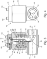
- mount 69 includes major bore 76, minor bore 78, and intermediate bore 80 joining major bore 76 to minor bore 78 and forming a passage through mount 69 from side channel 63 to head 70.
- Major bore 76 includes internal threads 82 which engage corresponding external threads 84 of housing 61 disposed about side channel 63.
- Interior end face 86 forms a transition between major bore 76 and intermediate bore 80.
- Groove 88 protrudes into mount 69 from interior end face 86 and extends circumferentially about side channel 63 and intermediate bore 80. Groove 88 retains seal 90 which can be an o-ring, a gasket, or other sealing element.
- Exterior surface 92 of mount 69 can be adapted to receive a tool for securing mount 69 to housing 61.
- exterior surface 92 can include at least a pair of parallel flat surfaces.
- exterior surface 92 may define a hexagonal cross-section of mount 69. Securing mount 69 to housing 61 compresses seal 90 between mount 69 and housing 61 to seal compressed air within side channel 63.
- head 70 includes cavity 93 and port 94.
- Cavity 93 extends into but not through head 70 to enclose bores 76, 78, and 80 of mount 69 and side channel 63 of housing 61.
- Port 94 extends through a peripheral wall of head 70 to providing a route for wire 68.
- a peripheral dimension of cavity 93 can overlap or circumscribe minor bore 78 of mount 69.
- One or more head seals 96 are received between head 70 and mount 69 to prevent or reduce compressed air leakage between head 70 and mount 69.
- Wire 68 can be routed from sensor 67 through side passage 63 of housing 61; major bore 76, intermediate bore 80, and minor bore 78 of mount 69; and cavity 93 and port 94 of head 70.
- Head 70 can be secured to mount 61 via one or more fasteners 100, which extend through an exterior end face of head 70 into mount 69.
- the combination of mount 69 and head 70 as depicted in FIG. 3 permits mount 69 to thread onto housing 69 without twisting or coiling wire 68 within side passage 63.
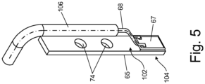
- FIG. 5 shows an isometric isolated view of the beam 65.
- FIG. 5 shows apertures 74 through the beam 65 through which the fasteners 66 can pass to mount the beam 65 to the housing 61.
- beam 65 has a rectangular cross-section.
- Major surfaces 102 and 104 of beam 65 provide flat regions for mounting sensor 67 and for engaging ledge 64.
- Wires 68 extend from sensor 67 along beam 65 and may be enclosed with protective cover 106, which can provide environmental and electrical protection.
- a control circuit may receive a plurality of outputs from a plurality of sensors 67 from a plurality of sensor modules 58 that monitor a plurality of bead flow lines supplying a plurality of bead dispensers 49.
- the control circuit can correlate the plurality of signals to a plurality of bead flow values and display the values on a screen of interface 16 and/or save the values to memory. This can be used to ensure balance in bead dispense, and allow adjustment if one bead line is supplying more than another.
- the control circuit can aggregate the values to calculate a total flow rate, representing the total or average outflow of beads from the bead hopper 19 and/or dispensed on the ground surface.
- the beam 65 may be formed from a resilient material.
- the beam 65 may be formed from metal.
- the beam 65 may be formed from polymer.
- the sensor 67 may be adhered to the beam 65 with adhesive (e.g., epoxy) and/or laminated onto the beam 65 under a coating.
- the bead hopper 19 may be the only source of beads for the bead dispensers 49.
- the compressor 18 may be the only source of the flow of compressed air.
- a bead flow sensor module includes a housing, a beam, and a sensor.
- the housing includes a flow channel.
- the beam extends into the flow channel.
- the sensor is configured to output a signal indicative of bead impact on the beam.
- the bead flow sensor module of the preceding paragraph can optionally include, additionally and/or alternatively, any one or more of the following features, configurations and/or additional components.
- a further embodiment of any of the foregoing bead flow sensor modules can include a side channel that branches from the flow channel.
- a further embodiment of any of the foregoing bead flow sensor modules can include one or more fasteners that secure the beam to the housing.
- a further embodiment of any of the foregoing bead flow sensor modules, wherein the one or more fasteners can be threaded bolts.
- a further embodiment of any of the foregoing bead flow sensor modules wherein the side channel can intersect the flow channel at an oblique angle such that the housing forms a Y shape.
- a further embodiment of any of the foregoing bead flow sensor modules wherein the ledge can abut the beam between a distal end within the flow channel and a proximal end secured to the housing within the side channel.
- a further embodiment of any of the foregoing bead flow sensor modules can include a mount engaging the housing.
- mount can include at least one bore extending through the mount.
- a further embodiment of any of the foregoing bead flow sensor modules can include a head attached to the mount.
- a further embodiment of any of the foregoing bead flow sensor modules wherein the mount and the head can enclose the side channel to form a dead-end.
- a system includes a source of a flow of compressed air, a bead hopper, a bead dispenser, a flow pathway between the bead hopper and the bead dispenser, and a bead flow sensor module.
- the bead hopper is supplied with the flow of compressed air, a flow of beads being carried with the flow of compressed air out of the bead hopper into the flow pathway.
- the bead flow sensor module is positioned along the flow pathway.
- the system of the preceding paragraph can optionally include, additionally and/or alternatively, any one or more of the following features, configurations and/or additional components.
- the bead flow sensor module can include a housing with a flow channel, a beam that extends into the flow channel, and a sensor configured to output a signal indicative of bead impact on the beam.
- side channel can include a dead-end opposite the flow channel.
- bead flow sensor module can be closer to the bead dispenser than the bead hopper along the flow pathway.
- a further embodiment of any of the foregoing systems can further include a plurality of flow pathways.
- each flow pathway of the plurality of flow pathways can extend between the bead dispenser and one of the plurality of bead dispensers.
- a further embodiment of any of the foregoing systems can further include a plurality of bead flow sensor modules.
- each bead flow sensor module of the plurality of bead flow sensor modules is positioned along one of the plurality of flow pathways.
- a ground stripe marking system includes a liquid reservoir, a spray outlet, a pump, a compressor, a bead hopper, a bead dispenser, and a bead flow sensor module.
- the pump is fluidly connected to the liquid reservoir to draw marking material from the liquid reservoir and discharge marking material through the spray outlet.
- the compressor provides a flow of compressed air.
- the bead hopper is supplied with the flow of compressed air, and the compressed air is configured to carry a flow of beads out of the bead hopper.
- the bead dispenser is connected to the bead hopper by a flow pathway between the bead hopper and the bead dispenser.
- the bead flow sensor module includes a sensor configured to output a signal indicative of bead flow through the bead flow sensor module.
- ground stripe marking system of the preceding paragraph can optionally include, additionally and/or alternatively, any one or more of the following features, configurations and/or additional components.
- a further embodiment of the foregoing ground stripe marking system wherein the bead flow sensor module can include a housing that includes a flow channel.
- a further embodiment of the foregoing ground stripe marking systems wherein the bead flow sensor module can include a beam that extends into the flow channel.
- a further embodiment of the foregoing ground stripe marking systems wherein the sensor can be configured to output a signal indicative of bead impact on the beam.
- a further embodiment of any of the foregoing ground stripe marking systems wherein the sensor can be located on an upstream side of the beam relative to a flow of beads through the flow channel.
- a further embodiment of any of the foregoing ground stripe marking systems can include a side channel that branches from the flow channel.
- a further embodiment of any of the foregoing ground stripe marking systems can include one or more fasteners that secure the beam to the housing.
- a further embodiment of any of the foregoing ground stripe marking systems, wherein the one or more fasteners can be threaded bolts.
- a further embodiment of any of the foregoing ground stripe marking systems wherein the housing can form a T shape.
- a further embodiment of any of the foregoing ground stripe marking systems wherein the side channel can intersect the flow channel at an oblique angle such that the housing forms a Y shape.
- a further embodiment of any of the foregoing ground stripe marking systems wherein the ledge can abut the beam between a distal end within the flow channel and a proximal end secured to the housing within the side channel.
- the housing can include one or more side apertures aligned with each of the one or more fasteners.
- a further embodiment of any of the foregoing ground stripe marking systems can include a mount engaging the housing.
- mount can include at least one bore extending through the mount.
- a further embodiment of any of the foregoing ground stripe marking systems can include a head attached to the mount.
- a further embodiment of any of the foregoing ground stripe marking systems wherein the mount and the head can enclose the side channel to form a dead-end.
- a further embodiment of any of the foregoing ground stripe marking systems can further include a plurality of bead dispensers.
- a further embodiment of any of the foregoing ground stripe marking systems can further include a plurality of flow pathways.
- each flow pathway of the plurality of flow pathways can extend between the bead dispenser and one of the plurality of bead dispensers.
- a further embodiment of any of the foregoing ground stripe marking systems can further include a plurality of bead flow sensor modules.
- each bead flow sensor module of the plurality of bead flow sensor modules is positioned along one of the plurality of flow pathways.
- a further embodiment of any of the foregoing ground stripe marking systems wherein at least one bead flow sensor module of the plurality of bead flow sensor modules can be closer to the bead dispenser than the bead hopper along one of the plurality of flow pathways.
- each bead flow sensor module of the plurality of bead flow sensor modules can be closer to the bead dispenser than the bead hopper along one of the plurality of flow pathways.
- a further embodiment of any of the foregoing ground stripe marking systems wherein at least one bead flow sensor module of the plurality of bead flow sensor modules can be adjacent to the bead dispenser along one of the plurality of flow pathways.
- each bead flow sensor module of the plurality of bead flow sensor modules can be adjacent to the bead dispenser along one of the plurality of flow pathways.
- the bead flow sensor module of Aspect 2 wherein the sensor is located on an upstream side of the beam relative to a flow of beads through the flow channel.
- the bead flow sensor module of Aspect 1 further comprising a side channel that branches from the flow channel, wherein the beam is partially located within the side channel.
- the bead flow sensor module of Aspect 1 further comprising one or more fasteners that secure the beam to the housing.
- the bead flow sensor module of Aspect 9 wherein the one or more fasteners are threaded bolts.
- a system comprising:
- a system comprising:
- a bead flow sensor module comprising:
- the bead flow sensor module of Aspect 16 wherein the sensor is mounted on the beam.
- the bead flow sensor module of Aspect 16 further comprising a side channel that branches from the flow channel, wherein the beam is partially located within the side channel.
- the bead flow sensor module of Aspect 19 further comprising a ledge formed at the intersection of the side channel and the flow channel, wherein the ledge abuts the beam between a distal end within the flow channel and a proximal end secured to the housing within the side channel.
- the bead flow sensor module of Aspect 19 further comprising a ledge formed at the intersection of the side channel and the flow channel, wherein the beam is spaced from the ledge and the ledge limits deflection of the beam.
- the bead flow sensor module of Aspect 17 further comprising one or more fasteners that secure the beam to the housing.
- a system comprising:
- a system comprising:
- a ground stripe marking system comprising:
- the ground stripe marking system of Aspect 31, wherein the bead flow sensor module comprises:
- the ground stripe marking system of Aspect 31 further comprising a hose fluidly connecting the bead hopper and the bead dispenser to form the flow pathway.
Landscapes
- Physics & Mathematics (AREA)
- Fluid Mechanics (AREA)
- General Physics & Mathematics (AREA)
- Structural Engineering (AREA)
- Architecture (AREA)
- Civil Engineering (AREA)
- Engineering & Computer Science (AREA)
- Chemical & Material Sciences (AREA)
- Analytical Chemistry (AREA)
- Coating Apparatus (AREA)
- Nozzles (AREA)
- Processing And Handling Of Plastics And Other Materials For Molding In General (AREA)
- Indicating Or Recording The Presence, Absence, Or Direction Of Movement (AREA)
- Geophysics And Detection Of Objects (AREA)
- Heating, Cooling, Or Curing Plastics Or The Like In General (AREA)
Applications Claiming Priority (2)
| Application Number | Priority Date | Filing Date | Title |
|---|---|---|---|
| US202163257936P | 2021-10-20 | 2021-10-20 | |
| EP22202490.3A EP4170293B1 (de) | 2021-10-20 | 2022-10-19 | Durchflusssensor für bodenmarkierungskügelchen |
Related Parent Applications (1)
| Application Number | Title | Priority Date | Filing Date |
|---|---|---|---|
| EP22202490.3A Division EP4170293B1 (de) | 2021-10-20 | 2022-10-19 | Durchflusssensor für bodenmarkierungskügelchen |
Publications (2)
| Publication Number | Publication Date |
|---|---|
| EP4480591A2 true EP4480591A2 (de) | 2024-12-25 |
| EP4480591A3 EP4480591A3 (de) | 2025-03-19 |
Family
ID=83899482
Family Applications (2)
| Application Number | Title | Priority Date | Filing Date |
|---|---|---|---|
| EP22202490.3A Active EP4170293B1 (de) | 2021-10-20 | 2022-10-19 | Durchflusssensor für bodenmarkierungskügelchen |
| EP24211732.3A Pending EP4480591A3 (de) | 2021-10-20 | 2022-10-19 | Durchflusssensor für bodenmarkierungskügelchen |
Family Applications Before (1)
| Application Number | Title | Priority Date | Filing Date |
|---|---|---|---|
| EP22202490.3A Active EP4170293B1 (de) | 2021-10-20 | 2022-10-19 | Durchflusssensor für bodenmarkierungskügelchen |
Country Status (4)
| Country | Link |
|---|---|
| US (1) | US20230123506A1 (de) |
| EP (2) | EP4170293B1 (de) |
| CN (1) | CN115992477A (de) |
| AU (1) | AU2022256133A1 (de) |
Family Cites Families (14)
| Publication number | Priority date | Publication date | Assignee | Title |
|---|---|---|---|---|
| US4791818A (en) * | 1987-07-20 | 1988-12-20 | Itt Corporation | Cantilever beam, insertable, vortex meter sensor |
| US5275504A (en) * | 1991-05-09 | 1994-01-04 | Linear Dynamics, Inc. | Glass bead application sensor system |
| CN2343576Y (zh) * | 1998-10-27 | 1999-10-13 | 泉州日新流量仪器仪表有限公司 | 数显靶式流量计 |
| CN2369216Y (zh) * | 1999-01-05 | 2000-03-15 | 万国庆 | 新型靶式流量计 |
| LU90883B1 (en) * | 2002-01-23 | 2003-07-24 | Wurth Paul Sa | Method and device for monotoring a mass flow in a pneumatic pipeline |
| US6547158B1 (en) * | 2002-07-12 | 2003-04-15 | Ramp Engineering, Inc. | Apparatus for applying line striping chemicals and reflective beads to a surface |
| US7921726B2 (en) * | 2006-06-12 | 2011-04-12 | Precision Pumping Systems, Inc. | Fluid sensor with mechanical positional feedback |
| US7850101B2 (en) * | 2008-11-21 | 2010-12-14 | Sightline, Lc | Line marking apparatus |
| IT1404207B1 (it) * | 2010-12-31 | 2013-11-15 | Acque Ingegneria | Dispositivo per misurare la portata di un fluido |
| US9021893B2 (en) * | 2011-12-08 | 2015-05-05 | Exquadrum, Inc. | High survivability fluid flow sensor having a load cell for detecting loading on the sensor probe |
| CN203719699U (zh) * | 2014-02-26 | 2014-07-16 | 纳米新能源(唐山)有限责任公司 | 用于管道监测的流量传感装置 |
| US10698427B2 (en) * | 2016-10-31 | 2020-06-30 | Ge Oil & Gas Pressure Control Lp | System and method for assessing sand flow rate |
| US20180120865A1 (en) * | 2016-10-31 | 2018-05-03 | General Electric Company | Systems and methods for detecting solid particles |
| CN209085679U (zh) * | 2018-12-03 | 2019-07-09 | 广州仪控自动化仪表有限公司 | 一种靶式流量计 |
-
2022
- 2022-10-19 CN CN202211283443.7A patent/CN115992477A/zh active Pending
- 2022-10-19 EP EP22202490.3A patent/EP4170293B1/de active Active
- 2022-10-19 EP EP24211732.3A patent/EP4480591A3/de active Pending
- 2022-10-19 US US17/969,459 patent/US20230123506A1/en active Pending
- 2022-10-19 AU AU2022256133A patent/AU2022256133A1/en active Pending
Also Published As
| Publication number | Publication date |
|---|---|
| EP4170293A3 (de) | 2023-05-03 |
| EP4170293B1 (de) | 2024-12-04 |
| AU2022256133A1 (en) | 2023-05-04 |
| US20230123506A1 (en) | 2023-04-20 |
| CN115992477A (zh) | 2023-04-21 |
| EP4170293A2 (de) | 2023-04-26 |
| EP4480591A3 (de) | 2025-03-19 |
Similar Documents
| Publication | Publication Date | Title |
|---|---|---|
| EP2125529B1 (de) | Modulares system zum aufbringen von heissen flüssigkeiten oder andern thermoplastischen materialien und ein dazugehöriges kontrollsystem | |
| US20040089234A1 (en) | System for spraying a fluid material | |
| US20140263708A1 (en) | Multi-section applicator with variable-rate sections | |
| US9463484B2 (en) | Spray assembly for surface treatment | |
| CN115121386A (zh) | 用于结构的自动移动涂装的系统 | |
| US20090197001A1 (en) | Fluid applicator assembly | |
| US7850101B2 (en) | Line marking apparatus | |
| CA2846024A1 (en) | High pressure applicator apparatus and methods | |
| US20160107179A1 (en) | System for dispensing multiple component chemical sprays | |
| AU2006201532A1 (en) | System and method for determining atomization characteristics of spray liquids | |
| US20160215461A1 (en) | Control system for applying a pavement coating emulsion | |
| US9511644B2 (en) | Liquid dispensing equipment with active suspension system | |
| EP4480591A2 (de) | Durchflusssensor für bodenmarkierungskügelchen | |
| EP3962259B1 (de) | Systeme und verfahren zur präzisen verteilung fluidischer landwirtschaftlicher artikel | |
| US20150308710A1 (en) | Fluid heater for a pumping system | |
| US20090208287A1 (en) | Zero velocity bead dispenser | |
| HU206910B (en) | Pulsating pump | |
| US9452453B2 (en) | System and method for uniformly applying a wetting agent to a treatment surface | |
| WO2026096480A1 (en) | Ground marking bead flow sensor | |
| EP3046682B1 (de) | Flüssigkeitsdruckregelungssystem für flüssigkeitsausgabesysteme | |
| CN111974571A (zh) | 涂料喷涂流量控制系统 | |
| BR102021015157A2 (pt) | Pulverizador de campo agrícola e dispositivo de pulverização para um pulverizador de campo agrícola | |
| JP2007152300A (ja) | 塗装システム | |
| CN110031395B (zh) | 横向力系数测试方法与路表水膜厚度控制方法 | |
| RU2757729C1 (ru) | Система и способ выброса огнетушащего вещества и пожарная машина с подъемником |
Legal Events
| Date | Code | Title | Description |
|---|---|---|---|
| PUAI | Public reference made under article 153(3) epc to a published international application that has entered the european phase |
Free format text: ORIGINAL CODE: 0009012 |
|
| STAA | Information on the status of an ep patent application or granted ep patent |
Free format text: STATUS: REQUEST FOR EXAMINATION WAS MADE |
|
| 17P | Request for examination filed |
Effective date: 20241108 |
|
| AC | Divisional application: reference to earlier application |
Ref document number: 4170293 Country of ref document: EP Kind code of ref document: P |
|
| AK | Designated contracting states |
Kind code of ref document: A2 Designated state(s): AL AT BE BG CH CY CZ DE DK EE ES FI FR GB GR HR HU IE IS IT LI LT LU LV MC ME MK MT NL NO PL PT RO RS SE SI SK SM TR |
|
| REG | Reference to a national code |
Ref country code: DE Ref legal event code: R079 Free format text: PREVIOUS MAIN CLASS: B05C0011100000 Ipc: G01F0001280000 |
|
| PUAL | Search report despatched |
Free format text: ORIGINAL CODE: 0009013 |
|
| AK | Designated contracting states |
Kind code of ref document: A3 Designated state(s): AL AT BE BG CH CY CZ DE DK EE ES FI FR GB GR HR HU IE IS IT LI LT LU LV MC ME MK MT NL NO PL PT RO RS SE SI SK SM TR |
|
| RIC1 | Information provided on ipc code assigned before grant |
Ipc: B05C 11/10 20060101ALI20250213BHEP Ipc: E01C 23/20 20060101ALI20250213BHEP Ipc: B05C 11/00 20060101ALI20250213BHEP Ipc: B05B 13/00 20060101ALI20250213BHEP Ipc: B05B 13/02 20060101ALI20250213BHEP Ipc: B05B 12/00 20180101ALI20250213BHEP Ipc: B05B 9/04 20060101ALI20250213BHEP Ipc: B05B 7/18 20060101ALI20250213BHEP Ipc: B05B 7/14 20060101ALI20250213BHEP Ipc: G01F 1/74 20060101ALI20250213BHEP Ipc: G01F 1/30 20060101ALI20250213BHEP Ipc: G01F 1/28 20060101AFI20250213BHEP |
|
| STAA | Information on the status of an ep patent application or granted ep patent |
Free format text: STATUS: EXAMINATION IS IN PROGRESS |