EP4480454A2 - Alternate stent caf design for tavr - Google Patents
Alternate stent caf design for tavr Download PDFInfo
- Publication number
- EP4480454A2 EP4480454A2 EP24204552.4A EP24204552A EP4480454A2 EP 4480454 A2 EP4480454 A2 EP 4480454A2 EP 24204552 A EP24204552 A EP 24204552A EP 4480454 A2 EP4480454 A2 EP 4480454A2
- Authority
- EP
- European Patent Office
- Prior art keywords
- stent
- attachment features
- commissure attachment
- leaflets
- commissure
- Prior art date
- Legal status (The legal status is an assumption and is not a legal conclusion. Google has not performed a legal analysis and makes no representation as to the accuracy of the status listed.)
- Pending
Links
Images




Classifications
-
- A—HUMAN NECESSITIES
- A61—MEDICAL OR VETERINARY SCIENCE; HYGIENE
- A61F—FILTERS IMPLANTABLE INTO BLOOD VESSELS; PROSTHESES; DEVICES PROVIDING PATENCY TO, OR PREVENTING COLLAPSING OF, TUBULAR STRUCTURES OF THE BODY, e.g. STENTS; ORTHOPAEDIC, NURSING OR CONTRACEPTIVE DEVICES; FOMENTATION; TREATMENT OR PROTECTION OF EYES OR EARS; BANDAGES, DRESSINGS OR ABSORBENT PADS; FIRST-AID KITS
- A61F2/00—Filters implantable into blood vessels; Prostheses, i.e. artificial substitutes or replacements for parts of the body; Appliances for connecting them with the body; Devices providing patency to, or preventing collapsing of, tubular structures of the body, e.g. stents
- A61F2/02—Prostheses implantable into the body
- A61F2/24—Heart valves ; Vascular valves, e.g. venous valves; Heart implants, e.g. passive devices for improving the function of the native valve or the heart muscle; Transmyocardial revascularisation [TMR] devices; Valves implantable in the body
- A61F2/2412—Heart valves ; Vascular valves, e.g. venous valves; Heart implants, e.g. passive devices for improving the function of the native valve or the heart muscle; Transmyocardial revascularisation [TMR] devices; Valves implantable in the body with soft flexible valve members, e.g. tissue valves shaped like natural valves
-
- A—HUMAN NECESSITIES
- A61—MEDICAL OR VETERINARY SCIENCE; HYGIENE
- A61F—FILTERS IMPLANTABLE INTO BLOOD VESSELS; PROSTHESES; DEVICES PROVIDING PATENCY TO, OR PREVENTING COLLAPSING OF, TUBULAR STRUCTURES OF THE BODY, e.g. STENTS; ORTHOPAEDIC, NURSING OR CONTRACEPTIVE DEVICES; FOMENTATION; TREATMENT OR PROTECTION OF EYES OR EARS; BANDAGES, DRESSINGS OR ABSORBENT PADS; FIRST-AID KITS
- A61F2/00—Filters implantable into blood vessels; Prostheses, i.e. artificial substitutes or replacements for parts of the body; Appliances for connecting them with the body; Devices providing patency to, or preventing collapsing of, tubular structures of the body, e.g. stents
- A61F2/02—Prostheses implantable into the body
- A61F2/24—Heart valves ; Vascular valves, e.g. venous valves; Heart implants, e.g. passive devices for improving the function of the native valve or the heart muscle; Transmyocardial revascularisation [TMR] devices; Valves implantable in the body
- A61F2/2412—Heart valves ; Vascular valves, e.g. venous valves; Heart implants, e.g. passive devices for improving the function of the native valve or the heart muscle; Transmyocardial revascularisation [TMR] devices; Valves implantable in the body with soft flexible valve members, e.g. tissue valves shaped like natural valves
- A61F2/2418—Scaffolds therefor, e.g. support stents
-
- A—HUMAN NECESSITIES
- A61—MEDICAL OR VETERINARY SCIENCE; HYGIENE
- A61F—FILTERS IMPLANTABLE INTO BLOOD VESSELS; PROSTHESES; DEVICES PROVIDING PATENCY TO, OR PREVENTING COLLAPSING OF, TUBULAR STRUCTURES OF THE BODY, e.g. STENTS; ORTHOPAEDIC, NURSING OR CONTRACEPTIVE DEVICES; FOMENTATION; TREATMENT OR PROTECTION OF EYES OR EARS; BANDAGES, DRESSINGS OR ABSORBENT PADS; FIRST-AID KITS
- A61F2/00—Filters implantable into blood vessels; Prostheses, i.e. artificial substitutes or replacements for parts of the body; Appliances for connecting them with the body; Devices providing patency to, or preventing collapsing of, tubular structures of the body, e.g. stents
- A61F2/02—Prostheses implantable into the body
- A61F2/24—Heart valves ; Vascular valves, e.g. venous valves; Heart implants, e.g. passive devices for improving the function of the native valve or the heart muscle; Transmyocardial revascularisation [TMR] devices; Valves implantable in the body
- A61F2/2409—Support rings therefor, e.g. for connecting valves to tissue
-
- A—HUMAN NECESSITIES
- A61—MEDICAL OR VETERINARY SCIENCE; HYGIENE
- A61F—FILTERS IMPLANTABLE INTO BLOOD VESSELS; PROSTHESES; DEVICES PROVIDING PATENCY TO, OR PREVENTING COLLAPSING OF, TUBULAR STRUCTURES OF THE BODY, e.g. STENTS; ORTHOPAEDIC, NURSING OR CONTRACEPTIVE DEVICES; FOMENTATION; TREATMENT OR PROTECTION OF EYES OR EARS; BANDAGES, DRESSINGS OR ABSORBENT PADS; FIRST-AID KITS
- A61F2/00—Filters implantable into blood vessels; Prostheses, i.e. artificial substitutes or replacements for parts of the body; Appliances for connecting them with the body; Devices providing patency to, or preventing collapsing of, tubular structures of the body, e.g. stents
- A61F2/02—Prostheses implantable into the body
- A61F2/24—Heart valves ; Vascular valves, e.g. venous valves; Heart implants, e.g. passive devices for improving the function of the native valve or the heart muscle; Transmyocardial revascularisation [TMR] devices; Valves implantable in the body
- A61F2/2412—Heart valves ; Vascular valves, e.g. venous valves; Heart implants, e.g. passive devices for improving the function of the native valve or the heart muscle; Transmyocardial revascularisation [TMR] devices; Valves implantable in the body with soft flexible valve members, e.g. tissue valves shaped like natural valves
- A61F2/2415—Manufacturing methods
-
- A—HUMAN NECESSITIES
- A61—MEDICAL OR VETERINARY SCIENCE; HYGIENE
- A61F—FILTERS IMPLANTABLE INTO BLOOD VESSELS; PROSTHESES; DEVICES PROVIDING PATENCY TO, OR PREVENTING COLLAPSING OF, TUBULAR STRUCTURES OF THE BODY, e.g. STENTS; ORTHOPAEDIC, NURSING OR CONTRACEPTIVE DEVICES; FOMENTATION; TREATMENT OR PROTECTION OF EYES OR EARS; BANDAGES, DRESSINGS OR ABSORBENT PADS; FIRST-AID KITS
- A61F2210/00—Particular material properties of prostheses classified in groups A61F2/00 - A61F2/26 or A61F2/82 or A61F9/00 or A61F11/00 or subgroups thereof
- A61F2210/0014—Particular material properties of prostheses classified in groups A61F2/00 - A61F2/26 or A61F2/82 or A61F9/00 or A61F11/00 or subgroups thereof using shape memory or superelastic materials, e.g. nitinol
-
- A—HUMAN NECESSITIES
- A61—MEDICAL OR VETERINARY SCIENCE; HYGIENE
- A61F—FILTERS IMPLANTABLE INTO BLOOD VESSELS; PROSTHESES; DEVICES PROVIDING PATENCY TO, OR PREVENTING COLLAPSING OF, TUBULAR STRUCTURES OF THE BODY, e.g. STENTS; ORTHOPAEDIC, NURSING OR CONTRACEPTIVE DEVICES; FOMENTATION; TREATMENT OR PROTECTION OF EYES OR EARS; BANDAGES, DRESSINGS OR ABSORBENT PADS; FIRST-AID KITS
- A61F2220/00—Fixations or connections for prostheses classified in groups A61F2/00 - A61F2/26 or A61F2/82 or A61F9/00 or A61F11/00 or subgroups thereof
- A61F2220/0025—Connections or couplings between prosthetic parts, e.g. between modular parts; Connecting elements
- A61F2220/0075—Connections or couplings between prosthetic parts, e.g. between modular parts; Connecting elements sutured, ligatured or stitched, retained or tied with a rope, string, thread, wire or cable
-
- A—HUMAN NECESSITIES
- A61—MEDICAL OR VETERINARY SCIENCE; HYGIENE
- A61F—FILTERS IMPLANTABLE INTO BLOOD VESSELS; PROSTHESES; DEVICES PROVIDING PATENCY TO, OR PREVENTING COLLAPSING OF, TUBULAR STRUCTURES OF THE BODY, e.g. STENTS; ORTHOPAEDIC, NURSING OR CONTRACEPTIVE DEVICES; FOMENTATION; TREATMENT OR PROTECTION OF EYES OR EARS; BANDAGES, DRESSINGS OR ABSORBENT PADS; FIRST-AID KITS
- A61F2250/00—Special features of prostheses classified in groups A61F2/00 - A61F2/26 or A61F2/82 or A61F9/00 or A61F11/00 or subgroups thereof
- A61F2250/0014—Special features of prostheses classified in groups A61F2/00 - A61F2/26 or A61F2/82 or A61F9/00 or A61F11/00 or subgroups thereof having different values of a given property or geometrical feature, e.g. mechanical property or material property, at different locations within the same prosthesis
- A61F2250/0036—Special features of prostheses classified in groups A61F2/00 - A61F2/26 or A61F2/82 or A61F9/00 or A61F11/00 or subgroups thereof having different values of a given property or geometrical feature, e.g. mechanical property or material property, at different locations within the same prosthesis differing in thickness
Definitions
- the present invention relates to collapsible prosthetic heart valves, and more particularly, to prosthetic heart valves having commissure attachment features that reduce strain on the leaflets of the prosthetic valve and methods of manufacturing the commissure attachment features.
- Prosthetic heart valves that are collapsible to a relatively small circumferential size can be delivered into a patient less invasively than valves that are not collapsible.
- a collapsible valve may be delivered into a patient via a tube-like delivery apparatus such as a catheter, a trocar, a laparoscopic instrument, or the like. This collapsibility can avoid the need for a more invasive procedure such as full open-chest, open-heart surgery.
- Collapsible prosthetic heart valves typically take the form of a valve structure mounted on a stent.
- a stent There are two types of stents on which the valve structures are ordinarily mounted: a self-expanding stent and a balloon-expandable stent.
- a self-expanding stent To place such valves into a delivery apparatus and ultimately into a patient, the valve must first be collapsed to reduce its circumferential size.
- the prosthetic valve When a collapsed prosthetic valve has reached the desired implant site in the patient (e.g., at or near the annulus of the patient's heart valve that is to be repaired by the prosthetic valve), the prosthetic valve can be deployed or released from the delivery apparatus and expanded to its full operating size.
- the desired implant site in the patient e.g., at or near the annulus of the patient's heart valve that is to be repaired by the prosthetic valve
- the prosthetic valve can be deployed or released from the delivery apparatus and expanded to its full operating size.
- this generally involves releasing the entire valve, assuring its proper location and then expanding a balloon positioned within the valve stent.
- the stent automatically expands as the stent is withdrawn from the delivery apparatus.
- Prosthetic aortic heart valves maintain unidirectional blood flow in the circulatory system by opening and closing, depending on the difference in the pressure on opposite sides of the valve. Prosthetic aortic heart valves prevent backflow from the aorta into the left ventricle during systole.
- prosthetic heart valves have limited life expectancies for a variety of reasons. Thrombus buildup, for example, may prevent the prosthetic leaflets from properly coapting. Moreover, the prosthetic heart valve may be susceptible to failure at high stress regions, such as the leaflet commissure attachment feature, causing the prosthetic leaflets to tear and/or the sutures that attach the prosthetic valve assembly to the stent to tear.
- a commissure attachment feature extends in a medial direction of a stent for coupling a valve assembly to the stent.
- this attachment feature permits adjacent leaflets to be sutured to one another to improve blood washout of the neo-sinus of the prosthetic heart valve to prevent the formation of thrombus, and to redistribute strain from the commissure of the leaflets to the stent. Redistributing the strain in this manner reduces the likelihood that the prosthetic leaflets will tear.
- One embodiment of the device includes a stent extending in a longitudinal direction and having a collapsed condition and an expanded condition.
- the stent includes a plurality of struts forming cells and a plurality of commissure attachment features spaced apart in an annular direction of the stent.
- Each of the commissure attachment features is attached to select ones of the struts and extends in a medial direction of the stent.
- a valve assembly is secured to the plurality of commissure attachment features, the valve assembly including a cuff and a plurality of leaflets, each of the leaflets having a free edge and being capable of alternating between an open position and a closed position.
- a method of manufacturing a prosthetic heart valve includes cutting a tubular material to form a stent, the stent extending in a longitudinal direction and having a collapsed condition and an expanded condition.
- the stent includes a plurality of struts forming cells and a plurality of commissure attachment features spaced apart in an annular direction of the stent.
- the method further includes bending each of the commissure attachment features from a first orientation to a second orientation different from the first orientation, and coupling a valve assembly to the commissure attachment features, the valve assembly including a cuff and a plurality of leaflets, each of the leaflets having a free edge and being capable of alternating between an open position and a closed position.
- proximal when used in connection with a prosthetic heart valve, refers to the end of the heart valve closest to the heart when the heart valve is implanted in a patient
- distal when used in connection with a prosthetic heart valve, refers to the end of the heart valve farthest from the heart when the heart valve is implanted in a patient.
- the terms “generally,” “substantially,” “approximately” and “about” are intended to mean that slight deviations from absolute are included within the scope of the term so modified.
- FIG. 1 illustrates a collapsible prosthetic heart valve 10 that is designed to replace the function of the native aortic valve of a patient.
- Prosthetic heart valve 10 includes an expandable stent 12 which may be formed from biocompatible materials that are capable of self-expansion, for example, shape memory alloys such as nitinol.
- Stent 12 extends from a proximal or annulus end 14 to a distal or aortic end 16, and includes an annulus section 18 adjacent the proximal end and an aortic section 20 adjacent the distal end.
- Annulus section 18 has a relatively small cross-section in an expanded condition compared to aortic section 20 in the expanded condition.
- Annulus section 18 maybe in the form of a cylinder having a substantially constant diameter along its length.
- a transition section 22 tapers outwardly from annulus section 18 to aortic section 20.
- Each of the sections of stent 12 includes a plurality of struts 24 which form a plurality of cells 26 that are connected to one another in one or more annular rows around the stent.
- Annulus section 18 may have two annular rows of complete cells and aortic section 20 and transition section 22 may each have one or more annular rows of partial cells.
- the cells in aortic section 20 may be larger than the cells in annulus section 18.
- the larger cells in aortic section 20 facilitate positioning prosthetic valve 10 within the native aortic annulus such that stent 12 does not interfere with blood flow to the coronary arteries.
- Stent 12 includes one or more retaining elements 28 at distal end 16.
- Retaining elements 28 are sized to cooperate with a corresponding retaining structure on a delivery device. This cooperation minimizes axial movement of the prosthetic heart valve relative to the delivery device during unsheathing or resheathing procedures, and prevents rotation of the prosthetic heart valve relative to the delivery device as the delivery device is advanced to the target location and during deployment.
- Stent 12 may also include a plurality of commissure attachment features 30 for attaching the commissure between two adjacent leaflets to the stent.
- commissure attachments features 30 are disposed within the wall of stent 12 and may lie at the intersection of four cells 26, two of the cells being adjacent to one another in the same annular row, and the other two cells being in different annular rows and lying in end-to-end relationship.
- Commissure attachment features 30 are preferably positioned entirely within annulus section 18, or at the juncture of the annulus section and transition section 22.
- Commissure attachment features 30 may include one or more eyelets 32 which facilitate the suturing of the leaflet commissure to stent 12.
- Prosthetic heart valve 10 also includes a valve assembly 34, which may be positioned entirely within annulus section 18 and secured to stent 12 by suturing the valve assembly to struts 24 and/or to commissure attachment features 30. That is, the entire valve assembly 34 may be axially positioned between the proximal end 14 of stent 12 and commissure attachment features 30, such that none of the valve assembly is positioned between the commissure attachment features and the distal end 16 of the stent.
- Valve assembly 34 includes a cuff 36 and a plurality of leaflets 38 which open and close collectively to function as a one-way valve. Both cuff 36 and leaflets 38 may be wholly or partly formed of any suitable biological material, such as bovine or porcine pericardium, or biocompatible polymers, such as PTFE, urethanes and the like.
- Prosthetic heart valve 10 may be used to replace a native valve, a surgical heart valve or a heart valve that has undergone a surgical procedure.
- Prosthetic heart valve 10 may be delivered to the desired site (e.g., near the native aortic annulus) using any suitable delivery device.
- prosthetic heart valve 10 is disposed inside the delivery device in a collapsed condition.
- the delivery device may be introduced into a patient using a transfemoral, transapical, transseptal or any other percutaneous approach.
- the user may deploy prosthetic heart valve 10.
- prosthetic heart valve 10 expands so that the annulus section 18 of stent 12 is in secure engagement within the native annulus.
- FIG. 2 is a highly schematic cutaway view showing prosthetic heart valve 10 disposed within the native aortic annulus of a patient.
- prosthetic heart valve 10 When prosthetic heart valve 10 is properly positioned within the native annulus, it works as a one-way valve, allowing blood to flow from the left ventricle of the heart to the aorta during systole, and preventing blood from flowing in the opposite direction.
- Long term clinical success, and ultimately the life of prosthetic heart valve 10 is dependent, in part, on the ability of the free edges of leaflets 38 to properly coapt. Thrombus buildup in the neo-sinus NS of prosthetic heart valve 10 may restrict motion of leaflets 38 and prevent the leaflets from coapting.
- FIG. 4 illustrates a prosthetic heart valve 110 according to an embodiment of the present invention.
- Prosthetic heart valve 110 includes all of the features of prosthetic heart valve 10, except for commissure attachment features 30. Accordingly, each of the features of prosthetic heart valve 110 that correspond to features of prosthetic heart valve 10 are not described again hereinafter. Instead, when such features are referenced or illustrated in FIGS. 4-7 , these features are described and illustrated using corresponding 100 series numerals.
- Prosthetic heart valve 110 replaces commissure attachment features 30 with commissure attachment features 130, shown in Fig. 5 .
- Commissure attachment features 130 are designed to redistribute strain from the leaflets 138 of prosthetic heart valve 110 to the stent 112 of the prosthetic heart valve.
- Commissure attachment features 130 are spaced apart from one another in an annular direction of stent 112 and disposed within a predetermined one of the annular rows of cells 126.
- commissure attachment features 130 are disposed in one of the rows of cells within the annulus section 118 of stent 112, or in one of the rows of cells at the juncture of the annulus section and the transition section 122 of the stent. Since FIG.
- prosthetic heart valve 110 for replacing a native tricuspid valve, such as the aortic valve
- prosthetic heart valve 110 is illustrated with three leaflets 138, as well as three commissure attachment features 130.
- prosthetic heart valves according to this aspect of the invention may have a greater or lesser number of leaflets 138 and/or commissure attachment features 130.
- the prosthetic heart valve may include two commissure attachment features 130 for attaching each of the two prosthetic leaflets 138 to stent 112.
- each one of the plurality of commissure attachment features 130 includes a body 140 that has a length in a longitudinal direction of stent 112, a width in a radial direction of the stent and a thickness (not shown) in an annular direction of the stent.
- the width of body 140 may be about 3.0 mm or less, and is preferably between about 2.0 mm and about 2.5 mm.
- Commissure attachment features 130 may be positioned above the bulk of leaflets 138. In light of this and that the commissure attachment features have a relatively small dimension in the medial direction of stent 112, the collapsibility of prosthetic heart valve 110 is not inhibited. Accordingly, prosthetic heart valve 110 can be collapsed into a competitive French delivery system, for example, an 18 French delivery device.
- the body 140 of commissure attachment feature 130 has a side 142 that is attached to select struts 124 of stent 112, and a free edge 144 that is disposed in an interior region the stent. That is, the body 140 of commissure attachment feature 130 extends from select struts 124 in a medial direction of stent 112 (i.e., toward the middle of the stent or radially inward). In other words, body 140 extends orthogonal to the annular direction of stent 112 toward the center of the stent.
- the body 140 of commissure attachment feature 130 may be shaped as a quarter ellipse, or a quarter circle, such that the free edge 144 of the body forms an arc extending from a distal end of the attached side 142 of the body to a proximal end of the free edge spaced radially inward from stent 112.
- the body 140 of commissure attachment feature 130 may include a plurality of apertures or eyelets for connecting valve assembly 134 to stent 112.
- body 140 may include an eyelet 146 for coupling cuff 136 to stent 112, and one or more smaller eyelets 148 for suturing adjacent leaflets 138 to one another and to the commissure attachment feature.
- At least one of leaflet attachment eyelets 148 may be spaced from the attached side 142 of commissure attachment feature 130 so as to be spaced from a luminal surface of stent 112.
- FIG. 6 is a flow chart depicting a method 200 of manufacturing prosthetic heart valve 110.
- a tube of nitinol is placed around a mandrel and cut, preferably by a laser or other technique, to form stent 112.
- FIG. 7 A fragmentary view of stent 112 after the tube has been cut and radially expanded is illustrated in FIG. 7 .
- commissure attachment features 130 initially extend in a lateral direction relative to the struts 124 of stent 112. That is, commissure attachment features 130 initially lie within the circumference of stent 112.
- commissure attachment features 130 are then heat set, or otherwise permanently set, in this position.
- cuff 136 may be attached to stent 112 in step 206, for example, by suturing the cuff to the stent.
- a suture may additionally be pierced through cuff 136 and passed through the cuff attachment eyelet 146 of commissure attachment feature 130 before the suture is again pierced through the cuff.
- This additional step may optionally be repeated for each one of commissure attachment features 130.
- the ends of adjacent leaflets may then be sutured together and coupled to the commissure attachment feature 130.
- a suture may pierce through a first one of the leaflets, pass through at least one of the leaflet attachment eyelets 148 of commissure attachment feature 130, and then pierce through an adjacent leaflet.
- the belly of each one of leaflets 138 may then be sutured to cuff 136 and stent 112.
- a series of suture loops extend along the belly of each one of the leaflets in a parabolic shape, and further secure the leaflets to the stent.
- the cross-sectional area of the lumen of prosthetic heart valve 110 is reduced, such that the velocity of blood flow through the lumen during systole will be increased.
- some of the blood will form an eddy in the neo-sinus, and wash out from the neo-sinus is improved and thrombus build up is reduced.
- adjacent leaflets are sutured together via medially extending commissure attachment features 130, when a stress is applied to the prosthetic valve leaflets 138, the stress is transferred away from the prosthetic leaflets to the commissure attachment features and stent 112. This reduces the likelihood that valve assembly 134 will fail under stress and prolongs the life of prosthetic heart valve 110.
- a prosthetic heart valve includes a stent extending in a longitudinal direction and having a collapsed condition and an expanded condition, the stent including a plurality of struts forming cells and a plurality of commissure attachment features spaced apart in an annular direction of the stent, each of the commissure attachment features being attached to select ones of the struts and extending in a medial direction of the stent; and a valve assembly secured to the plurality of the commissure attachment features, the valve assembly including a cuff and a plurality of leaflets, each of the leaflets having a free edge and being capable of alternating between an open position and a closed position; and/or
- a method of manufacturing a prosthetic heart valve includes cutting a tubular material to form a stent, the stent extending in a longitudinal direction and having a collapsed condition and an expanded condition, the stent including a plurality of struts forming cells and a plurality of commissure attachment features spaced apart in an annular direction of the stent; bending each of the commissure attachment features from a first orientation to a second orientation different from the first orientation; and coupling a valve assembly to the commissure attachment features, the valve assembly including a cuff and a plurality of leaflets, each of the leaflets having a free edge and being capable of alternating between an open position and a closed position; and/or
Landscapes
- Health & Medical Sciences (AREA)
- Engineering & Computer Science (AREA)
- Biomedical Technology (AREA)
- Cardiology (AREA)
- Oral & Maxillofacial Surgery (AREA)
- Transplantation (AREA)
- Heart & Thoracic Surgery (AREA)
- Vascular Medicine (AREA)
- Life Sciences & Earth Sciences (AREA)
- Animal Behavior & Ethology (AREA)
- General Health & Medical Sciences (AREA)
- Public Health (AREA)
- Veterinary Medicine (AREA)
- Manufacturing & Machinery (AREA)
- Prostheses (AREA)
Abstract
Description
- The present application claims the benefit of Application Serial No.
62/880,758, filed July 31, 2019 - The present invention relates to collapsible prosthetic heart valves, and more particularly, to prosthetic heart valves having commissure attachment features that reduce strain on the leaflets of the prosthetic valve and methods of manufacturing the commissure attachment features.
- Diseased and/or defective heart valves may lead to serious health complications. One method of addressing this condition is to replace a non-functioning heart valve with a prosthetic valve. Prosthetic heart valves that are collapsible to a relatively small circumferential size can be delivered into a patient less invasively than valves that are not collapsible. For example, a collapsible valve may be delivered into a patient via a tube-like delivery apparatus such as a catheter, a trocar, a laparoscopic instrument, or the like. This collapsibility can avoid the need for a more invasive procedure such as full open-chest, open-heart surgery.
- Collapsible prosthetic heart valves typically take the form of a valve structure mounted on a stent. There are two types of stents on which the valve structures are ordinarily mounted: a self-expanding stent and a balloon-expandable stent. To place such valves into a delivery apparatus and ultimately into a patient, the valve must first be collapsed to reduce its circumferential size.
- When a collapsed prosthetic valve has reached the desired implant site in the patient (e.g., at or near the annulus of the patient's heart valve that is to be repaired by the prosthetic valve), the prosthetic valve can be deployed or released from the delivery apparatus and expanded to its full operating size. For balloon-expandable valves, this generally involves releasing the entire valve, assuring its proper location and then expanding a balloon positioned within the valve stent. For self-expanding valves, on the other hand, the stent automatically expands as the stent is withdrawn from the delivery apparatus.
- Properly functioning prosthetic heart valves maintain unidirectional blood flow in the circulatory system by opening and closing, depending on the difference in the pressure on opposite sides of the valve. Prosthetic aortic heart valves prevent backflow from the aorta into the left ventricle during systole.
- Despite the improvements that have been made to prosthetic heart valves, various shortcomings remain. For example, prosthetic heart valves have limited life expectancies for a variety of reasons. Thrombus buildup, for example, may prevent the prosthetic leaflets from properly coapting. Moreover, the prosthetic heart valve may be susceptible to failure at high stress regions, such as the leaflet commissure attachment feature, causing the prosthetic leaflets to tear and/or the sutures that attach the prosthetic valve assembly to the stent to tear.
- Therefore, there is a need for improvements to the commissure attachment features of prosthetic heart valves that adequately secure the prosthetic leaflets to the stent in a manner that reduces the strain placed on the valve assembly without affecting the prosthetic heart valve's ability to collapse.
- In accordance with a first aspect of the present invention, a commissure attachment feature extends in a medial direction of a stent for coupling a valve assembly to the stent. Among other advantages, this attachment feature permits adjacent leaflets to be sutured to one another to improve blood washout of the neo-sinus of the prosthetic heart valve to prevent the formation of thrombus, and to redistribute strain from the commissure of the leaflets to the stent. Redistributing the strain in this manner reduces the likelihood that the prosthetic leaflets will tear.
- One embodiment of the device includes a stent extending in a longitudinal direction and having a collapsed condition and an expanded condition. The stent includes a plurality of struts forming cells and a plurality of commissure attachment features spaced apart in an annular direction of the stent. Each of the commissure attachment features is attached to select ones of the struts and extends in a medial direction of the stent. A valve assembly is secured to the plurality of commissure attachment features, the valve assembly including a cuff and a plurality of leaflets, each of the leaflets having a free edge and being capable of alternating between an open position and a closed position.
- A method of manufacturing a prosthetic heart valve is also provided. The method includes cutting a tubular material to form a stent, the stent extending in a longitudinal direction and having a collapsed condition and an expanded condition. The stent includes a plurality of struts forming cells and a plurality of commissure attachment features spaced apart in an annular direction of the stent. The method further includes bending each of the commissure attachment features from a first orientation to a second orientation different from the first orientation, and coupling a valve assembly to the commissure attachment features, the valve assembly including a cuff and a plurality of leaflets, each of the leaflets having a free edge and being capable of alternating between an open position and a closed position.
- Various embodiments of the present invention are described herein with reference to the drawings, wherein:
-
FIG. 1 is a side elevational view of a collapsible prosthetic heart valve in accordance with the prior art; -
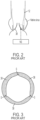
FIG. 2 is a highly schematic cutaway view of the prosthetic heart valve ofFIG. 1 disposed within the aortic valve annulus of patient; -
FIG. 3 is a highly schematic top view of the prosthetic heart valve ofFIG. 1 showing the commissure of adjacent leaflets sutured together; -
FIG. 4 is a side elevational view of a collapsible prosthetic heart valve in accordance with an embodiment of the present invention; -
FIG. 5 is a highly schematic cross-sectional view of the prosthetic heart valve ofFIG. 4 showing a commissure attachment feature in accordance with an embodiment of the present invention; -
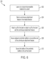
FIG. 6 is a flow chart showing a method of manufacturing the prosthetic heart valve ofFIG. 4 ; and -
FIG. 7 is a highly schematic fragmentary view of the stent of the prosthetic heart valve ofFIG. 4 . - As used herein, the term "proximal," when used in connection with a prosthetic heart valve, refers to the end of the heart valve closest to the heart when the heart valve is implanted in a patient, whereas the term "distal," when used in connection with a prosthetic heart valve, refers to the end of the heart valve farthest from the heart when the heart valve is implanted in a patient. As used herein, the terms "generally," "substantially," "approximately" and "about" are intended to mean that slight deviations from absolute are included within the scope of the term so modified.
-
FIG. 1 illustrates a collapsibleprosthetic heart valve 10 that is designed to replace the function of the native aortic valve of a patient.Prosthetic heart valve 10 includes anexpandable stent 12 which may be formed from biocompatible materials that are capable of self-expansion, for example, shape memory alloys such as nitinol.Stent 12 extends from a proximal orannulus end 14 to a distal or aortic end 16, and includes anannulus section 18 adjacent the proximal end and anaortic section 20 adjacent the distal end.Annulus section 18 has a relatively small cross-section in an expanded condition compared toaortic section 20 in the expanded condition. Annulussection 18 maybe in the form of a cylinder having a substantially constant diameter along its length. Atransition section 22 tapers outwardly fromannulus section 18 toaortic section 20. Each of the sections ofstent 12 includes a plurality ofstruts 24 which form a plurality ofcells 26 that are connected to one another in one or more annular rows around the stent.Annulus section 18 may have two annular rows of complete cells andaortic section 20 andtransition section 22 may each have one or more annular rows of partial cells. The cells inaortic section 20 may be larger than the cells inannulus section 18. The larger cells inaortic section 20 facilitate positioningprosthetic valve 10 within the native aortic annulus such thatstent 12 does not interfere with blood flow to the coronary arteries. - Stent 12 includes one or more retaining elements 28 at distal end 16. Retaining elements 28 are sized to cooperate with a corresponding retaining structure on a delivery device. This cooperation minimizes axial movement of the prosthetic heart valve relative to the delivery device during unsheathing or resheathing procedures, and prevents rotation of the prosthetic heart valve relative to the delivery device as the delivery device is advanced to the target location and during deployment.
-
Stent 12 may also include a plurality of commissure attachment features 30 for attaching the commissure between two adjacent leaflets to the stent. As shown inFIG. 1 , commissure attachments features 30 are disposed within the wall ofstent 12 and may lie at the intersection of fourcells 26, two of the cells being adjacent to one another in the same annular row, and the other two cells being in different annular rows and lying in end-to-end relationship.Commissure attachment features 30 are preferably positioned entirely withinannulus section 18, or at the juncture of the annulus section andtransition section 22.Commissure attachment features 30 may include one ormore eyelets 32 which facilitate the suturing of the leaflet commissure tostent 12. -
Prosthetic heart valve 10 also includes a valve assembly 34, which may be positioned entirely withinannulus section 18 and secured tostent 12 by suturing the valve assembly tostruts 24 and/or to commissure attachment features 30. That is, the entire valve assembly 34 may be axially positioned between theproximal end 14 ofstent 12 and commissure attachment features 30, such that none of the valve assembly is positioned between the commissure attachment features and the distal end 16 of the stent. Valve assembly 34 includes a cuff 36 and a plurality ofleaflets 38 which open and close collectively to function as a one-way valve. Both cuff 36 andleaflets 38 may be wholly or partly formed of any suitable biological material, such as bovine or porcine pericardium, or biocompatible polymers, such as PTFE, urethanes and the like. -
Prosthetic heart valve 10 may be used to replace a native valve, a surgical heart valve or a heart valve that has undergone a surgical procedure.Prosthetic heart valve 10 may be delivered to the desired site (e.g., near the native aortic annulus) using any suitable delivery device. During delivery,prosthetic heart valve 10 is disposed inside the delivery device in a collapsed condition. The delivery device may be introduced into a patient using a transfemoral, transapical, transseptal or any other percutaneous approach. Once the delivery device has reached the target site, the user may deployprosthetic heart valve 10. Upon deployment,prosthetic heart valve 10 expands so that theannulus section 18 ofstent 12 is in secure engagement within the native annulus. -
FIG. 2 is a highly schematic cutaway view showingprosthetic heart valve 10 disposed within the native aortic annulus of a patient. Whenprosthetic heart valve 10 is properly positioned within the native annulus, it works as a one-way valve, allowing blood to flow from the left ventricle of the heart to the aorta during systole, and preventing blood from flowing in the opposite direction. Long term clinical success, and ultimately the life ofprosthetic heart valve 10 is dependent, in part, on the ability of the free edges ofleaflets 38 to properly coapt. Thrombus buildup in the neo-sinus NS ofprosthetic heart valve 10 may restrict motion ofleaflets 38 and prevent the leaflets from coapting. - Suturing the commissures of
leaflets 38 radially inward of the commissure attachments features 30 ofstent 12, as shown inFIG. 3 , reduces the cross-sectional area of the lumen ofprosthetic heart valve 10, and results in increased velocity of blood flow through the neo-sinus during systole. The increased blood flow velocity is believed to improve blood wash out from the neo-sinus and reduce thrombus build up. However, the addition of sutures S places additional strain on theleaflets 38 of valve assembly 34 and increases the likelihood that the valve assembly will fail at this junction. Failure may, for example, include tearing of sutures S and/or theleaflets 38 of valve assembly 34. -
FIG. 4 illustrates aprosthetic heart valve 110 according to an embodiment of the present invention.Prosthetic heart valve 110 includes all of the features ofprosthetic heart valve 10, except for commissure attachment features 30. Accordingly, each of the features ofprosthetic heart valve 110 that correspond to features ofprosthetic heart valve 10 are not described again hereinafter. Instead, when such features are referenced or illustrated inFIGS. 4-7 , these features are described and illustrated using corresponding 100 series numerals. -
Prosthetic heart valve 110 replaces commissure attachment features 30 with commissure attachment features 130, shown inFig. 5 . Commissure attachment features 130 are designed to redistribute strain from theleaflets 138 ofprosthetic heart valve 110 to thestent 112 of the prosthetic heart valve. Commissure attachment features 130 are spaced apart from one another in an annular direction ofstent 112 and disposed within a predetermined one of the annular rows ofcells 126. Preferably, commissure attachment features 130 are disposed in one of the rows of cells within theannulus section 118 ofstent 112, or in one of the rows of cells at the juncture of the annulus section and thetransition section 122 of the stent. SinceFIG. 4 illustrates aprosthetic heart valve 110 for replacing a native tricuspid valve, such as the aortic valve,prosthetic heart valve 110 is illustrated with threeleaflets 138, as well as three commissure attachment features 130. However, it will be appreciated that prosthetic heart valves according to this aspect of the invention may have a greater or lesser number ofleaflets 138 and/or commissure attachment features 130. For example, ifprosthetic heart valve 110 were a prosthetic heart valve for replacing a native bicuspid valve, such as a mitral valve, the prosthetic heart valve may include two commissure attachment features 130 for attaching each of the twoprosthetic leaflets 138 tostent 112. - Referring to
FIG. 5 , each one of the plurality of commissure attachment features 130 includes abody 140 that has a length in a longitudinal direction ofstent 112, a width in a radial direction of the stent and a thickness (not shown) in an annular direction of the stent. The width ofbody 140 may be about 3.0 mm or less, and is preferably between about 2.0 mm and about 2.5 mm. Commissure attachment features 130 may be positioned above the bulk ofleaflets 138. In light of this and that the commissure attachment features have a relatively small dimension in the medial direction ofstent 112, the collapsibility ofprosthetic heart valve 110 is not inhibited. Accordingly,prosthetic heart valve 110 can be collapsed into a competitive French delivery system, for example, an 18 French delivery device. - The
body 140 ofcommissure attachment feature 130 has aside 142 that is attached to selectstruts 124 ofstent 112, and a free edge 144 that is disposed in an interior region the stent. That is, thebody 140 ofcommissure attachment feature 130 extends fromselect struts 124 in a medial direction of stent 112 (i.e., toward the middle of the stent or radially inward). In other words,body 140 extends orthogonal to the annular direction ofstent 112 toward the center of the stent. Thebody 140 ofcommissure attachment feature 130 may be shaped as a quarter ellipse, or a quarter circle, such that the free edge 144 of the body forms an arc extending from a distal end of the attachedside 142 of the body to a proximal end of the free edge spaced radially inward fromstent 112. - The
body 140 ofcommissure attachment feature 130 may include a plurality of apertures or eyelets for connectingvalve assembly 134 tostent 112. Thus,body 140 may include aneyelet 146 forcoupling cuff 136 tostent 112, and one or moresmaller eyelets 148 for suturingadjacent leaflets 138 to one another and to the commissure attachment feature. At least one of leaflet attachment eyelets 148 may be spaced from the attachedside 142 ofcommissure attachment feature 130 so as to be spaced from a luminal surface ofstent 112. -
FIG. 6 is a flow chart depicting amethod 200 of manufacturingprosthetic heart valve 110. In afirst step 202, a tube of nitinol is placed around a mandrel and cut, preferably by a laser or other technique, to formstent 112. A fragmentary view ofstent 112 after the tube has been cut and radially expanded is illustrated inFIG. 7 . As shown, commissure attachment features 130 initially extend in a lateral direction relative to thestruts 124 ofstent 112. That is, commissure attachment features 130 initially lie within the circumference ofstent 112. In anext step 204, the user may bend commissure attachment features 130 from their initial positions (e.g., the lateral or circumferential direction) to final positions (e.g., the medial or radial direction) as shown inFIG. 5 . Commissure attachment features 130 are then heat set, or otherwise permanently set, in this position. - After commissure attachment features 130 are set in their final positions,
cuff 136 may be attached tostent 112 instep 206, for example, by suturing the cuff to the stent. Although not required, a suture may additionally be pierced throughcuff 136 and passed through thecuff attachment eyelet 146 ofcommissure attachment feature 130 before the suture is again pierced through the cuff. This additional step may optionally be repeated for each one of commissure attachment features 130. The ends of adjacent leaflets may then be sutured together and coupled to thecommissure attachment feature 130. In thisstep 208, a suture may pierce through a first one of the leaflets, pass through at least one of the leaflet attachment eyelets 148 ofcommissure attachment feature 130, and then pierce through an adjacent leaflet. In afinal step 210, the belly of each one ofleaflets 138 may then be sutured tocuff 136 andstent 112. In an exemplary embodiment, a series of suture loops extend along the belly of each one of the leaflets in a parabolic shape, and further secure the leaflets to the stent. - By connecting the leaflet commissures to
commissure attachment feature 130 at a position spaced medially inward fromstent 112, the cross-sectional area of the lumen ofprosthetic heart valve 110 is reduced, such that the velocity of blood flow through the lumen during systole will be increased. As a result of the increased blood flow velocity, some of the blood will form an eddy in the neo-sinus, and wash out from the neo-sinus is improved and thrombus build up is reduced. Moreover, because adjacent leaflets are sutured together via medially extending commissure attachment features 130, when a stress is applied to theprosthetic valve leaflets 138, the stress is transferred away from the prosthetic leaflets to the commissure attachment features andstent 112. This reduces the likelihood thatvalve assembly 134 will fail under stress and prolongs the life ofprosthetic heart valve 110. - To summarize the foregoing, a prosthetic heart valve, includes a stent extending in a longitudinal direction and having a collapsed condition and an expanded condition, the stent including a plurality of struts forming cells and a plurality of commissure attachment features spaced apart in an annular direction of the stent, each of the commissure attachment features being attached to select ones of the struts and extending in a medial direction of the stent; and a valve assembly secured to the plurality of the commissure attachment features, the valve assembly including a cuff and a plurality of leaflets, each of the leaflets having a free edge and being capable of alternating between an open position and a closed position; and/or
- each of the commissure attachment features may extend substantially orthogonal to the annular direction of the stent; and/or
- the stent and the commissure attachment features may be integrally formed; and/or
- the stent and the commissure attachment features may be formed of nitinol; and/or
- each one of the commissure attachment features may be located in the annulus section of the stent and/or a width of the commissure attachment feature in the medial direction is about 3.0 mm or less; and/or
- a width of the commissure attachment feature in the medial direction may be between about 2.0 mm and about 2.5 mm; and/or
- the commissure attachment feature may include an eyelet; and/or
- the eyelet may be spaced in the medial direction from a luminal surface of the stent; and/or
- the cuff may be disposed on a luminal surface of the stent; and/or
- two of the leaflets may be sutured to each of the commissure attachment features; and/or
- each of the commissure attachment features may have a side attached to the stent and an arcuate edge extending between a distal end of the side and a proximal end of the arcuate edge spaced in the medial direction from the stent; and/or
- the stent may include three of the commissure attachment features; and/or
- the cells may be connected to one another in a plurality of annular rows about the stent, each one of the plurality of commissure attachment features being disposed in a predetermined one of the annular rows.
- A method of manufacturing a prosthetic heart valve is also provided. The method includes cutting a tubular material to form a stent, the stent extending in a longitudinal direction and having a collapsed condition and an expanded condition, the stent including a plurality of struts forming cells and a plurality of commissure attachment features spaced apart in an annular direction of the stent; bending each of the commissure attachment features from a first orientation to a second orientation different from the first orientation; and
coupling a valve assembly to the commissure attachment features, the valve assembly including a cuff and a plurality of leaflets, each of the leaflets having a free edge and being capable of alternating between an open position and a closed position; and/or - the first orientation may be an annular direction of the stent and the second orientation may be a medial direction of the stent; and/or
- the coupling step may comprise suturing each commissure formed by adjacent ones of the leaflets to a respective one of the commissure attachment features; and/or
- the method may further comprise suturing a belly of each one of the leaflets to the cuff and the stent; and/or
- the tubular material may be nitinol; and/or
- the method may further comprise heat setting the nitinol after the bending step.
- Although the invention herein has been described with reference to particular embodiments, it is to be understood that these embodiments are merely illustrative of the principles and applications of the present invention. It is therefore to be understood that numerous modifications may be made to the illustrative embodiments and that other arrangements may be devised without departing from the spirit and scope of the present invention as defined by the appended claims.
- The systems and methods described herein enable the repair of native heart valves that no longer function properly.
- Further examples of the present disclosure are set out in the following numbered clauses:
- Numbered clause 1. A prosthetic heart valve, comprising:
- a stent extending in a longitudinal direction and having a collapsed condition and an expanded condition, the stent including a plurality of struts forming cells and a plurality of commissure attachment features spaced apart in an annular direction of the stent, each of the commissure attachment features being attached to select ones of the struts and extending in a medial direction of the stent; and
- a valve assembly secured to the plurality of the commissure attachment features, the valve assembly including a cuff and a plurality of leaflets, each of the leaflets having a free edge and being capable of alternating between an open position and a closed position.
- Numbered clause 2. The valve of clause 1, wherein each of the commissure attachment features extends substantially orthogonal to the annular direction of the stent.
- Numbered clause 3. The valve of clause 1, wherein the stent and the commissure attachment features are integrally formed.
- Numbered clause 4. The valve of clause 1, wherein the stent and the commissure attachment features are formed of nitinol.
- Numbered clause 5. The valve of clause 1, wherein each one of the commissure attachment features is located in an annulus section of the stent.
- Numbered clause 6. The valve of clause 1, wherein a width of the commissure attachment feature in the medial direction is about 3.0 mm or less.
- Numbered clause 7. The valve of clause 1, wherein a width of the commissure attachment feature in the medial direction is between about 2.0 mm and about 2.5 mm.
- Numbered clause 8. The valve of clause 1, wherein the commissure attachment feature includes an eyelet.
- Numbered clause 9. The valve of clause 8, wherein the eyelet is spaced in the medial direction from a luminal surface of the stent.
- Numbered
clause 10. The valve of clause 1, wherein the cuff is disposed on a luminal surface of the stent. - Numbered clause 11. The valve of clause 1, wherein two of the leaflets are sutured to each of the commissure attachment features.
- Numbered
clause 12. The valve of clause 1, wherein each of the commissure attachment features has a side attached to the stent and an arcuate edge extending between a distal end of the side and a proximal end of the arcuate edge spaced in the medial direction from the stent. - Numbered clause 13. The valve of clause 1, wherein the stent includes three of the commissure attachment features.
- Numbered
clause 14. The valve of clause 1, wherein the cells are connected to one another in a plurality of annular rows about the stent, each one of the plurality of commissure attachment features being disposed in a predetermined one of the annular rows. - Numbered clause 15. A method of manufacturing a prosthetic heart valve, the method comprising:
- cutting a tubular material to form a stent, the stent extending in a longitudinal direction and having a collapsed condition and an expanded condition, the stent including a plurality of struts forming cells and a plurality of commissure attachment features spaced apart in an annular direction of the stent;
- bending each of the commissure attachment features from a first orientation to a second orientation different from the first orientation; and
- coupling a valve assembly to the commissure attachment features, the valve assembly including a cuff and a plurality of leaflets, each of the leaflets having a free edge and being capable of alternating between an open position and a closed position.
- Numbered clause 16. The method of clause 15, wherein the first orientation is an annular direction of the stent and the second orientation is a medial direction of the stent.
- Numbered clause 17. The method of clause 15, wherein the coupling step comprises suturing each commissure formed by adjacent ones of the leaflets to a respective one of the commissure attachment features.
- Numbered
clause 18. The method of clause 17, further comprising suturing a belly of each one of the leaflets to the cuff and the stent. - Numbered clause 19. The method of clause 15, wherein the tubular material is nitinol.
- Numbered
clause 20. The method of clause 19, further comprising heat setting the nitinol after the bending step.
Claims (15)
- A method of manufacturing a prosthetic heart valve, the method comprising:cutting a tubular material to form a stent, the stent extending in a longitudinal direction and having a collapsed condition and an expanded condition, the stent including a plurality of struts forming cells and a plurality of commissure attachment features spaced apart from one another in an annular direction of the stent, each of the plurality of commissure attachment features having a side attached to the stent and an arcuate edge extending from a distal end of the side to a proximal end spaced radially inward from the stent;bending each of the commissure attachment features about an axis from a first orientation to a second orientation different from the first orientation; andcoupling a valve assembly to the commissure attachment features, the valve assembly including a cuff and a plurality of leaflets, each of the leaflets having a free edge and being capable of alternating between an open position and a closed position.
- The method of claim 1, wherein the first orientation is the annular direction of the stent and the second orientation is a radial direction of the stent.
- The method of claim 1, wherein the coupling step includes suturing each commissure formed by adjacent ones of the leaflets to a respective one of the commissure attachment features.
- The method of claim 3, wherein each of the commissure attachment features includes an eyelet spaced in a radial direction from a luminal surface of the stent.
- The method of claim 4, wherein the suturing step includes piercing a suture through the cuff and through the eyelet of the respective one of the commissure attachment features.
- The method of claim 3, wherein the suturing step includes suturing the adjacent ones of the leaflets to each other.
- The method of claim 1, wherein the coupling step includes attaching each commissure formed by adjacent ones of the leaflets to a respective one of the commissure attachment features at a position spaced radially inward from the stent.
- The method of claim 1, wherein the tubular material is nitinol, the method further comprising heat setting the nitinol after the bending step.
- The method of claim 1, wherein each of the commissure attachment features is attached to select ones of the struts and, after the bending step, has a thickness in the annular direction and a width extending from the select ones of the struts in a radial direction of the stent toward a longitudinal axis of the stent.
- The method of claim 9, wherein the width of each of the commissure attachment features in the radial direction is about 3.0 mm or less.
- The method of claim 1, wherein the tubular material is placed around a mandrel prior to the cutting step.
- The method of claim 1, wherein the stent has a circumference and, prior to the bending step, each of the commissure attachment features lies within the circumference.
- The method of claim 1, wherein the cutting step forms the cells in a plurality of annular rows about the stent, and each of the commissure attachment features is disposed in a predetermined one of the annular rows.
- The method of claim 13, wherein the predetermined one of the annular rows is in an annulus section of the stent.
- The method of claim 1, wherein each of the commissure attachment features includes an eyelet, and the coupling step includes suturing the cuff to the plurality of commissure attachment features.
Applications Claiming Priority (3)
| Application Number | Priority Date | Filing Date | Title |
|---|---|---|---|
| US201962880758P | 2019-07-31 | 2019-07-31 | |
| PCT/US2020/042776 WO2021021482A1 (en) | 2019-07-31 | 2020-07-20 | Alternate stent caf design for tavr |
| EP20753609.5A EP4003230B1 (en) | 2019-07-31 | 2020-07-20 | Alternate stent caf design for tavr |
Related Parent Applications (2)
| Application Number | Title | Priority Date | Filing Date |
|---|---|---|---|
| EP20753609.5A Division-Into EP4003230B1 (en) | 2019-07-31 | 2020-07-20 | Alternate stent caf design for tavr |
| EP20753609.5A Division EP4003230B1 (en) | 2019-07-31 | 2020-07-20 | Alternate stent caf design for tavr |
Publications (2)
| Publication Number | Publication Date |
|---|---|
| EP4480454A2 true EP4480454A2 (en) | 2024-12-25 |
| EP4480454A3 EP4480454A3 (en) | 2025-07-09 |
Family
ID=71995147
Family Applications (2)
| Application Number | Title | Priority Date | Filing Date |
|---|---|---|---|
| EP20753609.5A Active EP4003230B1 (en) | 2019-07-31 | 2020-07-20 | Alternate stent caf design for tavr |
| EP24204552.4A Pending EP4480454A3 (en) | 2019-07-31 | 2020-07-20 | Alternate stent caf design for tavr |
Family Applications Before (1)
| Application Number | Title | Priority Date | Filing Date |
|---|---|---|---|
| EP20753609.5A Active EP4003230B1 (en) | 2019-07-31 | 2020-07-20 | Alternate stent caf design for tavr |
Country Status (3)
| Country | Link |
|---|---|
| US (2) | US11672654B2 (en) |
| EP (2) | EP4003230B1 (en) |
| WO (1) | WO2021021482A1 (en) |
Families Citing this family (11)
| Publication number | Priority date | Publication date | Assignee | Title |
|---|---|---|---|---|
| US11833034B2 (en) | 2016-01-13 | 2023-12-05 | Shifamed Holdings, Llc | Prosthetic cardiac valve devices, systems, and methods |
| WO2020041495A1 (en) | 2018-08-21 | 2020-02-27 | Shifamed, Llc | Prosthetic cardiac valve devices, systems, and methods |
| US10912644B2 (en) | 2018-10-05 | 2021-02-09 | Shifamed Holdings, Llc | Prosthetic cardiac valve devices, systems, and methods |
| WO2020082039A1 (en) | 2018-10-19 | 2020-04-23 | Shifamed Holdings, Llc | Adjustable medical device |
| EP3941391B1 (en) | 2019-03-19 | 2024-12-04 | Shifamed Holdings, LLC | Prosthetic cardiac valve devices, systems |
| US20240415642A1 (en) * | 2020-04-24 | 2024-12-19 | ReValve Solutions Inc. | Devices, systems, and methods for a valve replacement |
| US12616572B2 (en) | 2020-05-15 | 2026-05-05 | ReValve Solutions, Inc. | Devices, systems, and methods for a valve replacement |
| JP7821166B2 (en) | 2020-08-31 | 2026-02-26 | シファメド・ホールディングス・エルエルシー | Prosthetic valve delivery system |
| EP4216875A4 (en) | 2020-09-23 | 2024-11-13 | Revalve Solutions Inc. | Devices, systems, and methods for an implantable heart-valve adapter |
| JP7835754B2 (en) | 2020-12-04 | 2026-03-25 | シファメド・ホールディングス・エルエルシー | Protruding artificial heart valve delivery device and system |
| US12201521B2 (en) | 2021-03-22 | 2025-01-21 | Shifamed Holdings, Llc | Anchor position verification for prosthetic cardiac valve devices |
Family Cites Families (156)
| Publication number | Priority date | Publication date | Assignee | Title |
|---|---|---|---|---|
| US3657744A (en) | 1970-05-08 | 1972-04-25 | Univ Minnesota | Method for fixing prosthetic implants in a living body |
| US4491986A (en) | 1976-05-12 | 1985-01-08 | Shlomo Gabbay | Heart valve |
| US4275469A (en) | 1979-12-13 | 1981-06-30 | Shelhigh Inc. | Prosthetic heart valve |
| US4759758A (en) | 1984-12-07 | 1988-07-26 | Shlomo Gabbay | Prosthetic heart valve |
| DE3640745A1 (en) | 1985-11-30 | 1987-06-04 | Ernst Peter Prof Dr M Strecker | Catheter for producing or extending connections to or between body cavities |
| US4878906A (en) | 1986-03-25 | 1989-11-07 | Servetus Partnership | Endoprosthesis for repairing a damaged vessel |
| US4994077A (en) | 1989-04-21 | 1991-02-19 | Dobben Richard L | Artificial heart valve for implantation in a blood vessel |
| US5411552A (en) | 1990-05-18 | 1995-05-02 | Andersen; Henning R. | Valve prothesis for implantation in the body and a catheter for implanting such valve prothesis |
| US5843167A (en) | 1993-04-22 | 1998-12-01 | C. R. Bard, Inc. | Method and apparatus for recapture of hooked endoprosthesis |
| US5480423A (en) | 1993-05-20 | 1996-01-02 | Boston Scientific Corporation | Prosthesis delivery |
| US5713950A (en) | 1993-11-01 | 1998-02-03 | Cox; James L. | Method of replacing heart valves using flexible tubes |
| EP0657147B1 (en) | 1993-11-04 | 1999-08-04 | C.R. Bard, Inc. | Non-migrating vascular prosthesis |
| US5415664A (en) | 1994-03-30 | 1995-05-16 | Corvita Corporation | Method and apparatus for introducing a stent or a stent-graft |
| GB9522332D0 (en) | 1995-11-01 | 1996-01-03 | Biocompatibles Ltd | Braided stent |
| DE69526857T2 (en) | 1995-11-27 | 2003-01-02 | Schneider (Europe) Gmbh, Buelach | Stent for use in one pass |
| US7238197B2 (en) | 2000-05-30 | 2007-07-03 | Devax, Inc. | Endoprosthesis deployment system for treating vascular bifurcations |
| US5855601A (en) | 1996-06-21 | 1999-01-05 | The Trustees Of Columbia University In The City Of New York | Artificial heart valve and method and device for implanting the same |
| EP0850607A1 (en) | 1996-12-31 | 1998-07-01 | Cordis Corporation | Valve prosthesis for implantation in body channels |
| US6488702B1 (en) | 1997-01-24 | 2002-12-03 | Jomed Gmbh | Bistable spring construction for a stent and other medical apparatus |
| US5961549A (en) | 1997-04-03 | 1999-10-05 | Baxter International Inc. | Multi-leaflet bioprosthetic heart valve |
| US5910170A (en) * | 1997-12-17 | 1999-06-08 | St. Jude Medical, Inc. | Prosthetic heart valve stent utilizing mounting clips |
| US5938697A (en) | 1998-03-04 | 1999-08-17 | Scimed Life Systems, Inc. | Stent having variable properties |
| US5935163A (en) | 1998-03-31 | 1999-08-10 | Shelhigh, Inc. | Natural tissue heart valve prosthesis |
| US7452371B2 (en) | 1999-06-02 | 2008-11-18 | Cook Incorporated | Implantable vascular device |
| US6254564B1 (en) | 1998-09-10 | 2001-07-03 | Percardia, Inc. | Left ventricular conduit with blood vessel graft |
| US6214036B1 (en) | 1998-11-09 | 2001-04-10 | Cordis Corporation | Stent which is easily recaptured and repositioned within the body |
| DE19857887B4 (en) | 1998-12-15 | 2005-05-04 | Fraunhofer-Gesellschaft zur Förderung der angewandten Forschung e.V. | Anchoring support for a heart valve prosthesis |
| US6558414B2 (en) | 1999-02-02 | 2003-05-06 | Impra, Inc. | Partial encapsulation of stents using strips and bands |
| US6090140A (en) | 1999-02-17 | 2000-07-18 | Shelhigh, Inc. | Extra-anatomic heart valve apparatus |
| US6264691B1 (en) | 1999-04-23 | 2001-07-24 | Shlomo Gabbay | Apparatus and method for supporting a heart valve |
| HK1050470A1 (en) | 1999-09-10 | 2003-06-27 | E. Thorpe Patricia | Endovascular treatment for chronic venous insufficiency |
| US6440164B1 (en) | 1999-10-21 | 2002-08-27 | Scimed Life Systems, Inc. | Implantable prosthetic valve |
| FR2800984B1 (en) | 1999-11-17 | 2001-12-14 | Jacques Seguin | DEVICE FOR REPLACING A HEART VALVE PERCUTANEOUSLY |
| US8016877B2 (en) | 1999-11-17 | 2011-09-13 | Medtronic Corevalve Llc | Prosthetic valve for transluminal delivery |
| US8579966B2 (en) | 1999-11-17 | 2013-11-12 | Medtronic Corevalve Llc | Prosthetic valve for transluminal delivery |
| US7018406B2 (en) | 1999-11-17 | 2006-03-28 | Corevalve Sa | Prosthetic valve for transluminal delivery |
| US20070043435A1 (en) | 1999-11-17 | 2007-02-22 | Jacques Seguin | Non-cylindrical prosthetic valve system for transluminal delivery |
| US7195641B2 (en) | 1999-11-19 | 2007-03-27 | Advanced Bio Prosthetic Surfaces, Ltd. | Valvular prostheses having metal or pseudometallic construction and methods of manufacture |
| US6458153B1 (en) | 1999-12-31 | 2002-10-01 | Abps Venture One, Ltd. | Endoluminal cardiac and venous valve prostheses and methods of manufacture and delivery thereof |
| CA2398640C (en) | 2000-01-31 | 2011-06-14 | Cook Biotech Incorporated | Stent valves and uses of same |
| US6454799B1 (en) | 2000-04-06 | 2002-09-24 | Edwards Lifesciences Corporation | Minimally-invasive heart valves and methods of use |
| US6610088B1 (en) | 2000-05-03 | 2003-08-26 | Shlomo Gabbay | Biologically covered heart valve prosthesis |
| US6368348B1 (en) | 2000-05-15 | 2002-04-09 | Shlomo Gabbay | Annuloplasty prosthesis for supporting an annulus of a heart valve |
| US6869444B2 (en) | 2000-05-22 | 2005-03-22 | Shlomo Gabbay | Low invasive implantable cardiac prosthesis and method for helping improve operation of a heart valve |
| US6419695B1 (en) | 2000-05-22 | 2002-07-16 | Shlomo Gabbay | Cardiac prosthesis for helping improve operation of a heart valve |
| WO2002022054A1 (en) | 2000-09-12 | 2002-03-21 | Gabbay S | Valvular prosthesis and method of using same |
| US7510572B2 (en) | 2000-09-12 | 2009-03-31 | Shlomo Gabbay | Implantation system for delivery of a heart valve prosthesis |
| US6685625B2 (en) | 2000-09-26 | 2004-02-03 | Shlomo Gabbay | Curved implantable sheath and method of making same |
| US20020036220A1 (en) | 2000-09-26 | 2002-03-28 | Shlomo Gabbay | Curved implantable sheath and method of making same |
| US6783556B1 (en) | 2000-09-26 | 2004-08-31 | Shlomo Gabbay | System and method for making a calotte-shaped implantable sheath |
| US6517576B2 (en) | 2000-12-11 | 2003-02-11 | Shlomo Gabbay | Implantable patch prosthesis having one or more cusps for improved competency |
| ES2253325T3 (en) | 2000-12-15 | 2006-06-01 | ANGIOMED GMBH & CO. MEDIZINTECHNIK KG | ENDOVASCULAR PROTESIS WITH VALVE. |
| US6468660B2 (en) | 2000-12-29 | 2002-10-22 | St. Jude Medical, Inc. | Biocompatible adhesives |
| WO2002067782A2 (en) | 2001-02-26 | 2002-09-06 | Ev3 Peripheral, Inc. | Implant delivery system with interlock |
| US6623518B2 (en) | 2001-02-26 | 2003-09-23 | Ev3 Peripheral, Inc. | Implant delivery system with interlock |
| US7556646B2 (en) | 2001-09-13 | 2009-07-07 | Edwards Lifesciences Corporation | Methods and apparatuses for deploying minimally-invasive heart valves |
| DE10121210B4 (en) | 2001-04-30 | 2005-11-17 | Universitätsklinikum Freiburg | Anchoring element for the intraluminal anchoring of a heart valve replacement and method for its production |
| FR2828091B1 (en) | 2001-07-31 | 2003-11-21 | Seguin Jacques | ASSEMBLY ALLOWING THE PLACEMENT OF A PROTHETIC VALVE IN A BODY DUCT |
| US20080021552A1 (en) | 2001-10-09 | 2008-01-24 | Shlomo Gabbay | Apparatus To Facilitate Implantation |
| US6893460B2 (en) | 2001-10-11 | 2005-05-17 | Percutaneous Valve Technologies Inc. | Implantable prosthetic valve |
| DE10221076A1 (en) | 2002-05-11 | 2003-11-27 | Ruesch Willy Gmbh | stent |
| US7137184B2 (en) | 2002-09-20 | 2006-11-21 | Edwards Lifesciences Corporation | Continuous heart valve support frame and method of manufacture |
| US6814746B2 (en) | 2002-11-01 | 2004-11-09 | Ev3 Peripheral, Inc. | Implant delivery system with marker interlock |
| FR2847800B1 (en) | 2002-11-28 | 2005-10-14 | Perouse Laboratoires | INTERCHANGEABLE PROTHETIC VALVE |
| FR2850008A1 (en) | 2003-01-17 | 2004-07-23 | Daniel Roux | Vascular prosthesis has tube and collar for adapting to blood vessel ends of different diameters |
| ATE401843T1 (en) | 2003-03-20 | 2008-08-15 | Aortech Internat Plc | VALVE |
| CA2523262C (en) | 2003-04-24 | 2012-01-24 | Cook Incorporated | Artificial valve prosthesis with improved flow dynamics |
| US7717952B2 (en) | 2003-04-24 | 2010-05-18 | Cook Incorporated | Artificial prostheses with preferred geometries |
| US7201772B2 (en) | 2003-07-08 | 2007-04-10 | Ventor Technologies, Ltd. | Fluid flow prosthetic device |
| US7160322B2 (en) | 2003-08-13 | 2007-01-09 | Shlomo Gabbay | Implantable cardiac prosthesis for mitigating prolapse of a heart valve |
| US20060259137A1 (en) | 2003-10-06 | 2006-11-16 | Jason Artof | Minimally invasive valve replacement system |
| US10219899B2 (en) | 2004-04-23 | 2019-03-05 | Medtronic 3F Therapeutics, Inc. | Cardiac valve replacement systems |
| DE10394350B4 (en) | 2003-12-23 | 2018-05-17 | Cormove | To be implanted in a lumen to be implanted parts set and prosthesis the same |
| US20050137686A1 (en) | 2003-12-23 | 2005-06-23 | Sadra Medical, A Delaware Corporation | Externally expandable heart valve anchor and method |
| US8182528B2 (en) | 2003-12-23 | 2012-05-22 | Sadra Medical, Inc. | Locking heart valve anchor |
| US8840663B2 (en) | 2003-12-23 | 2014-09-23 | Sadra Medical, Inc. | Repositionable heart valve method |
| US9005273B2 (en) | 2003-12-23 | 2015-04-14 | Sadra Medical, Inc. | Assessing the location and performance of replacement heart valves |
| US8343213B2 (en) | 2003-12-23 | 2013-01-01 | Sadra Medical, Inc. | Leaflet engagement elements and methods for use thereof |
| US8828078B2 (en) | 2003-12-23 | 2014-09-09 | Sadra Medical, Inc. | Methods and apparatus for endovascular heart valve replacement comprising tissue grasping elements |
| US7311730B2 (en) | 2004-02-13 | 2007-12-25 | Shlomo Gabbay | Support apparatus and heart valve prosthesis for sutureless implantation |
| US7247167B2 (en) | 2004-02-19 | 2007-07-24 | Shlomo Gabbay | Low profile heart valve prosthesis |
| ITTO20040135A1 (en) | 2004-03-03 | 2004-06-03 | Sorin Biomedica Cardio Spa | CARDIAC VALVE PROSTHESIS |
| EP2308425B2 (en) | 2004-03-11 | 2023-10-18 | Percutaneous Cardiovascular Solutions Pty Limited | Percutaneous Heart Valve Prosthesis |
| US7374573B2 (en) | 2004-05-03 | 2008-05-20 | Shlomo Gabbay | System and method for improving ventricular function |
| US20050256566A1 (en) | 2004-05-03 | 2005-11-17 | Shlomo Gabbay | Apparatus and method for improving ventricular function |
| US20060122692A1 (en) | 2004-05-10 | 2006-06-08 | Ran Gilad | Stent valve and method of using same |
| US20060008497A1 (en) | 2004-07-09 | 2006-01-12 | Shlomo Gabbay | Implantable apparatus having improved biocompatibility and process of making the same |
| FR2874812B1 (en) | 2004-09-07 | 2007-06-15 | Perouse Soc Par Actions Simpli | INTERCHANGEABLE PROTHETIC VALVE |
| CA3050938C (en) | 2004-10-02 | 2021-10-19 | Edwards Lifesciences Cardiaq Llc | Methods and devices for repair or replacement of heart valves or adjacent tissue without the need for full cardiopulmonary support |
| US8562672B2 (en) | 2004-11-19 | 2013-10-22 | Medtronic, Inc. | Apparatus for treatment of cardiac valves and method of its manufacture |
| US7544205B2 (en) | 2004-12-20 | 2009-06-09 | Cook Incorporated | Intraluminal support frame and medical devices including the support frame |
| DE102005003632A1 (en) | 2005-01-20 | 2006-08-17 | Fraunhofer-Gesellschaft zur Förderung der angewandten Forschung e.V. | Catheter for the transvascular implantation of heart valve prostheses |
| ITTO20050074A1 (en) | 2005-02-10 | 2006-08-11 | Sorin Biomedica Cardio Srl | CARDIAC VALVE PROSTHESIS |
| US7331991B2 (en) | 2005-02-25 | 2008-02-19 | California Institute Of Technology | Implantable small percutaneous valve and methods of delivery |
| SE531468C2 (en) | 2005-04-21 | 2009-04-14 | Edwards Lifesciences Ag | An apparatus for controlling blood flow |
| EP3266414B1 (en) | 2005-05-12 | 2024-07-17 | Covidien LP | Implant delivery system with interlocked rx port orientation |
| US7914569B2 (en) | 2005-05-13 | 2011-03-29 | Medtronics Corevalve Llc | Heart valve prosthesis and methods of manufacture and use |
| WO2006127412A1 (en) | 2005-05-20 | 2006-11-30 | The Cleveland Clinic Foundation | Apparatus and methods for repairing the function of a diseased valve and method for making same |
| WO2007013999A2 (en) | 2005-07-21 | 2007-02-01 | Florida International University | Collapsible heart valve with polymer leaflets |
| US8790396B2 (en) | 2005-07-27 | 2014-07-29 | Medtronic 3F Therapeutics, Inc. | Methods and systems for cardiac valve delivery |
| US20080269879A1 (en) | 2005-07-27 | 2008-10-30 | Rahul Dilip Sathe | Implantable Prosthetic Vascular Valve |
| US8702777B2 (en) | 2005-08-22 | 2014-04-22 | Incept, Llc | Steep-taper flared stents and apparatus and methods for delivering them |
| US20070067029A1 (en) | 2005-09-16 | 2007-03-22 | Shlomo Gabbay | Support apparatus to facilitate implantation of cardiac prosthesis |
| US8092525B2 (en) | 2005-10-26 | 2012-01-10 | Cardiosolutions, Inc. | Heart valve implant |
| US20070118210A1 (en) | 2005-11-18 | 2007-05-24 | Leonard Pinchuk | Trileaflet Heart Valve |
| MX2008008068A (en) | 2005-12-22 | 2008-09-10 | Symetis Sa | Stent-valves for valve replacement and associated methods and systems for surgery. |
| US20070213813A1 (en) | 2005-12-22 | 2007-09-13 | Symetis Sa | Stent-valves for valve replacement and associated methods and systems for surgery |
| US8075615B2 (en) | 2006-03-28 | 2011-12-13 | Medtronic, Inc. | Prosthetic cardiac valve formed from pericardium material and methods of making same |
| US7524331B2 (en) | 2006-04-06 | 2009-04-28 | Medtronic Vascular, Inc. | Catheter delivered valve having a barrier to provide an enhanced seal |
| US20070244545A1 (en) | 2006-04-14 | 2007-10-18 | Medtronic Vascular, Inc. | Prosthetic Conduit With Radiopaque Symmetry Indicators |
| EP3400908B2 (en) | 2006-05-30 | 2026-04-22 | Cook Medical Technologies LLC | Artificial valve prosthesis |
| US20080097595A1 (en) | 2006-08-22 | 2008-04-24 | Shlomo Gabbay | Intraventricular cardiac prosthesis |
| US8876895B2 (en) | 2006-09-19 | 2014-11-04 | Medtronic Ventor Technologies Ltd. | Valve fixation member having engagement arms |
| US7534261B2 (en) | 2006-10-02 | 2009-05-19 | Edwards Lifesciences Corporation | Sutureless heart valve attachment |
| US8747459B2 (en) | 2006-12-06 | 2014-06-10 | Medtronic Corevalve Llc | System and method for transapical delivery of an annulus anchored self-expanding valve |
| FR2909857B1 (en) | 2006-12-14 | 2009-03-06 | Perouse Soc Par Actions Simpli | Endovalve. |
| US8236045B2 (en) | 2006-12-22 | 2012-08-07 | Edwards Lifesciences Corporation | Implantable prosthetic valve assembly and method of making the same |
| US20100087907A1 (en) | 2007-02-16 | 2010-04-08 | Emory University | Apparatus And Methods For Treating The Aorta |
| JP5367700B2 (en) | 2007-06-04 | 2013-12-11 | セント ジュード メディカル インコーポレイテッド | Prosthetic heart valve |
| JP2010528760A (en) | 2007-06-08 | 2010-08-26 | セント ジュード メディカル インコーポレイテッド | Device for transcatheter prosthetic heart valve implantation and access closure |
| ES2475144T3 (en) | 2007-06-26 | 2014-07-10 | St. Jude Medical, Inc. | Apparatus for implanting prosthetic heart valves folding / expandable |
| JP5419875B2 (en) | 2007-08-24 | 2014-02-19 | セント ジュード メディカル インコーポレイテッド | Artificial aortic heart valve |
| US8425593B2 (en) | 2007-09-26 | 2013-04-23 | St. Jude Medical, Inc. | Collapsible prosthetic heart valves |
| WO2009045334A1 (en) | 2007-09-28 | 2009-04-09 | St. Jude Medical, Inc. | Collapsible/expandable prosthetic heart valves with native calcified leaflet retention features |
| US8454686B2 (en) | 2007-09-28 | 2013-06-04 | St. Jude Medical, Inc. | Two-stage collapsible/expandable prosthetic heart valves and anchoring systems |
| US20090138079A1 (en) | 2007-10-10 | 2009-05-28 | Vector Technologies Ltd. | Prosthetic heart valve for transfemoral delivery |
| US9848981B2 (en) | 2007-10-12 | 2017-12-26 | Mayo Foundation For Medical Education And Research | Expandable valve prosthesis with sealing mechanism |
| ES2380555T3 (en) | 2007-11-05 | 2012-05-16 | St. Jude Medical, Inc. | Foldable / expandable prosthetic heart valves with non-expandable stent brackets and recovery features |
| US20080114452A1 (en) | 2007-11-14 | 2008-05-15 | Shlomo Gabbay | Prosthesis exhibiting post-implantation size change |
| AU2009205739B2 (en) | 2008-01-16 | 2014-09-25 | St. Jude Medical, Inc. | Delivery and retrieval systems for collapsible/expandable prosthetic heart valves |
| CA2715448C (en) | 2008-02-25 | 2017-06-13 | Medtronic Vascular Inc. | Infundibular reducer devices |
| ATE554731T1 (en) | 2008-05-16 | 2012-05-15 | Sorin Biomedica Cardio Srl | ATRAAUMATIC PROSTHETIC HEART VALVE PROSTHESIS |
| HUE047762T2 (en) | 2008-06-06 | 2020-05-28 | Edwards Lifesciences Corp | Low profile transcatheter heart valve |
| DE202008009610U1 (en) | 2008-07-17 | 2008-12-11 | Nvt Ag | Prosthetic heart valve system |
| US20100217382A1 (en) | 2009-02-25 | 2010-08-26 | Edwards Lifesciences | Mitral valve replacement with atrial anchoring |
| AU2010236288A1 (en) | 2009-04-15 | 2011-10-20 | Cardiaq Valve Technologies, Inc. | Vascular implant and delivery system |
| US8845722B2 (en) | 2009-08-03 | 2014-09-30 | Shlomo Gabbay | Heart valve prosthesis and method of implantation thereof |
| AU2010315030B2 (en) | 2009-11-05 | 2016-03-10 | The Trustees Of The University Of Pennsylvania | Valve prosthesis |
| US20120046729A1 (en) * | 2010-04-14 | 2012-02-23 | Abbott Vascular | Intraluminal scaffold having an enlarged portion |
| USD652926S1 (en) | 2010-09-20 | 2012-01-24 | St. Jude Medical, Inc. | Forked end |
| USD648854S1 (en) | 2010-09-20 | 2011-11-15 | St. Jude Medical, Inc. | Commissure points |
| USD660432S1 (en) | 2010-09-20 | 2012-05-22 | St. Jude Medical, Inc. | Commissure point |
| USD653342S1 (en) | 2010-09-20 | 2012-01-31 | St. Jude Medical, Inc. | Stent connections |
| USD654169S1 (en) | 2010-09-20 | 2012-02-14 | St. Jude Medical Inc. | Forked ends |
| USD654170S1 (en) | 2010-09-20 | 2012-02-14 | St. Jude Medical, Inc. | Stent connections |
| USD660967S1 (en) | 2010-09-20 | 2012-05-29 | St. Jude Medical, Inc. | Surgical stent |
| USD652927S1 (en) | 2010-09-20 | 2012-01-24 | St. Jude Medical, Inc. | Surgical stent |
| USD653341S1 (en) | 2010-09-20 | 2012-01-31 | St. Jude Medical, Inc. | Surgical stent |
| USD684692S1 (en) | 2010-09-20 | 2013-06-18 | St. Jude Medical, Inc. | Forked ends |
| USD653343S1 (en) | 2010-09-20 | 2012-01-31 | St. Jude Medical, Inc. | Surgical cuff |
| USD660433S1 (en) | 2010-09-20 | 2012-05-22 | St. Jude Medical, Inc. | Surgical stent assembly |
| US20140005776A1 (en) * | 2012-06-29 | 2014-01-02 | St. Jude Medical, Cardiology Division, Inc. | Leaflet attachment for function in various shapes and sizes |
| US10004597B2 (en) * | 2012-07-03 | 2018-06-26 | St. Jude Medical, Cardiology Division, Inc. | Stent and implantable valve incorporating same |
| CN111419472B (en) * | 2013-11-11 | 2023-01-10 | 爱德华兹生命科学卡迪尔克有限责任公司 | System and method for manufacturing stent frames |
| JP7068444B2 (en) * | 2017-09-27 | 2022-05-16 | ダブリュ.エル.ゴア アンド アソシエイツ,インコーポレイティド | Artificial valves with expandable frames, as well as related systems and methods |
| CN215425315U (en) * | 2018-11-14 | 2022-01-07 | 爱德华兹生命科学公司 | Prosthetic heart valve with commissure support elements |
-
2020
- 2020-07-20 WO PCT/US2020/042776 patent/WO2021021482A1/en not_active Ceased
- 2020-07-20 US US16/933,324 patent/US11672654B2/en active Active
- 2020-07-20 EP EP20753609.5A patent/EP4003230B1/en active Active
- 2020-07-20 EP EP24204552.4A patent/EP4480454A3/en active Pending
-
2023
- 2023-04-27 US US18/307,896 patent/US20230270543A1/en active Pending
Also Published As
| Publication number | Publication date |
|---|---|
| WO2021021482A1 (en) | 2021-02-04 |
| US20230270543A1 (en) | 2023-08-31 |
| EP4003230A1 (en) | 2022-06-01 |
| EP4003230B1 (en) | 2024-12-04 |
| EP4480454A3 (en) | 2025-07-09 |
| US11672654B2 (en) | 2023-06-13 |
| US20210030536A1 (en) | 2021-02-04 |
Similar Documents
| Publication | Publication Date | Title |
|---|---|---|
| US20230270543A1 (en) | Alternate Stent CAF Design for TAVR | |
| US12011350B2 (en) | Rapid implant prosthetic heart valve system | |
| US10842623B2 (en) | Methods of implanting prosthetic heart valve using position markers | |
| US10016274B2 (en) | Stent for prosthetic heart valves | |
| EP2129332B1 (en) | Replacement prosthetic heart valves | |
| US20190201194A1 (en) | Valve Assembly for Crimp Profile | |
| US11284996B2 (en) | Attachment of leaflets to prosthetic heart valve | |
| US20230355381A1 (en) | Detachable Cell Configuration for Valve in Valve | |
| US11678980B2 (en) | Fully-transseptal apical pad with pulley for tensioning | |
| US12144727B2 (en) | Tether attachment for mitral valve | |
| US12138163B2 (en) | Fully deployable and recapturable prosthetic heart valve |
Legal Events
| Date | Code | Title | Description |
|---|---|---|---|
| PUAI | Public reference made under article 153(3) epc to a published international application that has entered the european phase |
Free format text: ORIGINAL CODE: 0009012 |
|
| STAA | Information on the status of an ep patent application or granted ep patent |
Free format text: STATUS: THE APPLICATION HAS BEEN PUBLISHED |
|
| AC | Divisional application: reference to earlier application |
Ref document number: 4003230 Country of ref document: EP Kind code of ref document: P |
|
| AK | Designated contracting states |
Kind code of ref document: A2 Designated state(s): AL AT BE BG CH CY CZ DE DK EE ES FI FR GB GR HR HU IE IS IT LI LT LU LV MC MK MT NL NO PL PT RO RS SE SI SK SM TR |
|
| PUAL | Search report despatched |
Free format text: ORIGINAL CODE: 0009013 |
|
| AK | Designated contracting states |
Kind code of ref document: A3 Designated state(s): AL AT BE BG CH CY CZ DE DK EE ES FI FR GB GR HR HU IE IS IT LI LT LU LV MC MK MT NL NO PL PT RO RS SE SI SK SM TR |
|
| RIC1 | Information provided on ipc code assigned before grant |
Ipc: A61F 2/24 20060101AFI20250605BHEP |
|
| STAA | Information on the status of an ep patent application or granted ep patent |
Free format text: STATUS: REQUEST FOR EXAMINATION WAS MADE |
|
| 17P | Request for examination filed |
Effective date: 20251030 |