EP4478499A1 - Electrochemical apparatus and electrical device - Google Patents
Electrochemical apparatus and electrical device Download PDFInfo
- Publication number
- EP4478499A1 EP4478499A1 EP22929382.4A EP22929382A EP4478499A1 EP 4478499 A1 EP4478499 A1 EP 4478499A1 EP 22929382 A EP22929382 A EP 22929382A EP 4478499 A1 EP4478499 A1 EP 4478499A1
- Authority
- EP
- European Patent Office
- Prior art keywords
- edge
- folded
- main body
- arc edge
- electrochemical apparatus
- Prior art date
- Legal status (The legal status is an assumption and is not a legal conclusion. Google has not performed a legal analysis and makes no representation as to the accuracy of the status listed.)
- Pending
Links
Images

Classifications
-
- H—ELECTRICITY
- H01—ELECTRIC ELEMENTS
- H01M—PROCESSES OR MEANS, e.g. BATTERIES, FOR THE DIRECT CONVERSION OF CHEMICAL ENERGY INTO ELECTRICAL ENERGY
- H01M50/00—Constructional details or processes of manufacture of the non-active parts of electrochemical cells other than fuel cells, e.g. hybrid cells
- H01M50/10—Primary casings; Jackets or wrappings
- H01M50/102—Primary casings; Jackets or wrappings characterised by their shape or physical structure
- H01M50/105—Pouches or flexible bags
-
- H—ELECTRICITY
- H01—ELECTRIC ELEMENTS
- H01M—PROCESSES OR MEANS, e.g. BATTERIES, FOR THE DIRECT CONVERSION OF CHEMICAL ENERGY INTO ELECTRICAL ENERGY
- H01M50/00—Constructional details or processes of manufacture of the non-active parts of electrochemical cells other than fuel cells, e.g. hybrid cells
- H01M50/10—Primary casings; Jackets or wrappings
- H01M50/183—Sealing members
- H01M50/184—Sealing members characterised by their shape or structure
-
- H—ELECTRICITY
- H01—ELECTRIC ELEMENTS
- H01M—PROCESSES OR MEANS, e.g. BATTERIES, FOR THE DIRECT CONVERSION OF CHEMICAL ENERGY INTO ELECTRICAL ENERGY
- H01M10/00—Secondary cells; Manufacture thereof
- H01M10/04—Construction or manufacture in general
- H01M10/0431—Cells with wound or folded electrodes
-
- H—ELECTRICITY
- H01—ELECTRIC ELEMENTS
- H01M—PROCESSES OR MEANS, e.g. BATTERIES, FOR THE DIRECT CONVERSION OF CHEMICAL ENERGY INTO ELECTRICAL ENERGY
- H01M10/00—Secondary cells; Manufacture thereof
- H01M10/05—Accumulators with non-aqueous electrolyte
- H01M10/058—Construction or manufacture
- H01M10/0585—Construction or manufacture of accumulators having only flat construction elements, i.e. flat positive electrodes, flat negative electrodes and flat separators
-
- H—ELECTRICITY
- H01—ELECTRIC ELEMENTS
- H01M—PROCESSES OR MEANS, e.g. BATTERIES, FOR THE DIRECT CONVERSION OF CHEMICAL ENERGY INTO ELECTRICAL ENERGY
- H01M10/00—Secondary cells; Manufacture thereof
- H01M10/05—Accumulators with non-aqueous electrolyte
- H01M10/058—Construction or manufacture
- H01M10/0587—Construction or manufacture of accumulators having only wound construction elements, i.e. wound positive electrodes, wound negative electrodes and wound separators
-
- H—ELECTRICITY
- H01—ELECTRIC ELEMENTS
- H01M—PROCESSES OR MEANS, e.g. BATTERIES, FOR THE DIRECT CONVERSION OF CHEMICAL ENERGY INTO ELECTRICAL ENERGY
- H01M50/00—Constructional details or processes of manufacture of the non-active parts of electrochemical cells other than fuel cells, e.g. hybrid cells
- H01M50/10—Primary casings; Jackets or wrappings
- H01M50/102—Primary casings; Jackets or wrappings characterised by their shape or physical structure
- H01M50/103—Primary casings; Jackets or wrappings characterised by their shape or physical structure prismatic or rectangular
-
- H—ELECTRICITY
- H01—ELECTRIC ELEMENTS
- H01M—PROCESSES OR MEANS, e.g. BATTERIES, FOR THE DIRECT CONVERSION OF CHEMICAL ENERGY INTO ELECTRICAL ENERGY
- H01M50/00—Constructional details or processes of manufacture of the non-active parts of electrochemical cells other than fuel cells, e.g. hybrid cells
- H01M50/10—Primary casings; Jackets or wrappings
- H01M50/116—Primary casings; Jackets or wrappings characterised by the material
- H01M50/117—Inorganic material
- H01M50/119—Metals
-
- H—ELECTRICITY
- H01—ELECTRIC ELEMENTS
- H01M—PROCESSES OR MEANS, e.g. BATTERIES, FOR THE DIRECT CONVERSION OF CHEMICAL ENERGY INTO ELECTRICAL ENERGY
- H01M50/00—Constructional details or processes of manufacture of the non-active parts of electrochemical cells other than fuel cells, e.g. hybrid cells
- H01M50/10—Primary casings; Jackets or wrappings
- H01M50/116—Primary casings; Jackets or wrappings characterised by the material
- H01M50/124—Primary casings; Jackets or wrappings characterised by the material having a layered structure
-
- H—ELECTRICITY
- H01—ELECTRIC ELEMENTS
- H01M—PROCESSES OR MEANS, e.g. BATTERIES, FOR THE DIRECT CONVERSION OF CHEMICAL ENERGY INTO ELECTRICAL ENERGY
- H01M50/00—Constructional details or processes of manufacture of the non-active parts of electrochemical cells other than fuel cells, e.g. hybrid cells
- H01M50/10—Primary casings; Jackets or wrappings
- H01M50/131—Primary casings; Jackets or wrappings characterised by physical properties, e.g. gas permeability, size or heat resistance
- H01M50/136—Flexibility or foldability
-
- H—ELECTRICITY
- H01—ELECTRIC ELEMENTS
- H01M—PROCESSES OR MEANS, e.g. BATTERIES, FOR THE DIRECT CONVERSION OF CHEMICAL ENERGY INTO ELECTRICAL ENERGY
- H01M50/00—Constructional details or processes of manufacture of the non-active parts of electrochemical cells other than fuel cells, e.g. hybrid cells
- H01M50/10—Primary casings; Jackets or wrappings
- H01M50/183—Sealing members
- H01M50/186—Sealing members characterised by the disposition of the sealing members
-
- Y—GENERAL TAGGING OF NEW TECHNOLOGICAL DEVELOPMENTS; GENERAL TAGGING OF CROSS-SECTIONAL TECHNOLOGIES SPANNING OVER SEVERAL SECTIONS OF THE IPC; TECHNICAL SUBJECTS COVERED BY FORMER USPC CROSS-REFERENCE ART COLLECTIONS [XRACs] AND DIGESTS
- Y02—TECHNOLOGIES OR APPLICATIONS FOR MITIGATION OR ADAPTATION AGAINST CLIMATE CHANGE
- Y02E—REDUCTION OF GREENHOUSE GAS [GHG] EMISSIONS, RELATED TO ENERGY GENERATION, TRANSMISSION OR DISTRIBUTION
- Y02E60/00—Enabling technologies; Technologies with a potential or indirect contribution to GHG emissions mitigation
- Y02E60/10—Energy storage using batteries
Definitions
- This application relates to the technical field of energy storage, and in particular, to an electrochemical apparatus and an electric device.
- a first aspect of this application provides an electrochemical apparatus including a housing.
- the housing includes a main body part and a sealed part extending outward from an edge of the main body part.
- the main body part is configured to accommodate an electrode assembly.
- the sealed part includes a first outer edge, an outer arc edge, and a second outer edge.
- the outer arc edge connects the first outer edge and the second outer edge.
- the outer arc edge protrudes toward the main body part.
- a minimum curvature radius of the outer arc edge is r min mm, satisfying: r min ⁇ 0.3.
- r min ⁇ 5.
- a small notch is present at the outer arc edge, which can improve the sealing strength at the inner corner, thereby reducing the risk of tear and damage to the sealed part at the inner corner of the battery under drop conditions.
- the sealed part further includes an inner arc edge, the inner arc edge protrudes toward the main body part, and a distance from a position of a minimum curvature radius of the outer arc edge to the inner arc edge is D min mm, satisfying: D min ⁇ r min ⁇ 0.1.
- a sealing width at the position of the minimum curvature radius of the outer arc edge can match the stress applied to this position, which can reduce the risk of the position of the minimum curvature radius being completely torn, improving the sealing reliability of the electrochemical apparatus.
- D min ⁇ 1 which can increase the sealing width at the position of the minimum curvature radius of the outer arc edge at the inner corner, thereby increasing the sealing strength at this position and reducing the risk of failure of the sealed part at the inner corner.
- a minimum curvature radius of the inner arc edge is R min mm, satisfying: R min ⁇ 2.
- the sealed part includes a first folded edge part and a second folded edge part, the first outer edge is provided on the first folded edge part, and the second outer edge is provided on the second folded edge part.
- a shearing force applied to the sealed part can be reduced, thereby reducing the risk of the first outer edge and the second outer edge being torn and improving the sealing reliability of the electrochemical apparatus.
- the first folded edge part extends along a first direction
- the second folded edge part extends along a second direction
- the first direction intersects with the second direction
- the first folded edge part includes a first folded portion and a second folded portion, the second folded portion being located between the first folded portion and the main body part.
- the provision of the first folded portion and the second folded portion can improve the sealing reliability of the first folded edge part.
- the second folded edge part includes a third folded portion and a fourth folded portion, the fourth folded portion being located between the third folded portion and the main body part.
- the provision of the third folded portion and the fourth folded portion can improve the sealing reliability of the second folded edge part.
- a shape of the housing includes any one of L shape, V shape, U shape, or W shape.
- the electrode assembly includes at least one of a wound structure or a laminated structure.
- a second aspect of this application further provides an electric device including the electrochemical apparatus according to any one of the foregoing embodiments.
- setting the minimum curvature radius of the outer arc edge to be greater than or equal to 0.5 mm can reduce the stress concentration on the sealed part at the inner corner under drop conditions, thereby reducing the risk of tear and damage to the sealed part at the inner corner of the battery under drop conditions, which otherwise causes safety accidents.
- Electrochemical apparatus 100 Housing 10 Main body part 10a Sealed part 10b First folded edge part 101a Second folded edge part 102a First outer edge 101 Outer arc edge 102 Second outer edge 103 Inner arc edge 104 First shell 11 Second shell 12 First extension part 11a First extension section 111 Third extension section 112 Second extension part 12a Second extension section 121 Fourth extension section 122 Sealed area 1011 Unsealed area 1012 Tab assembly 20 First tab 21 Second tab 22
- the first folded edge part 101a extends along a first direction
- the second folded edge part 102a extends along a second direction
- the first direction intersects with the second direction.
- the first direction is perpendicular to the second direction.
- the first folded edge part 101a includes a first folded portion and a second folded portion.
- the first folded portion and the second folded portion are formed by folding along a width direction of the first folded edge part 101a, and the second folded portion is connected to the main body part 10a and the first folded portion.
- the second folded portion is located between the first folded portion and the main body part 10a. The provision of the first folded portion and the second folded portion can improve the sealing reliability of the first folded edge part 101a.
- L-shaped lithium-ion batteries with different r min values, D min ⁇ r min values, and D min values, R min being 5 mm, and first outer edges and second outer edges being single folded edges, were subjected to drop test and hot box test.
- Drop test method 10 lithium-ion batteries were taken and dropped freely from a height of 1.2 m and repeatedly dropped for 20 times, and the number of lithium-ion batteries with sealed parts torn at the inner corners after dropped (that is, the number of tears in drop test) and the number of lithium-ion batteries with sealed parts completely torn at the inner corners (that is, the number of sealing failures in drop test) were counted.
- Hot box test method 10 lithium-ion batteries were taken and placed in an oven at 150°C for 30 minutes, and were observed to determine whether electrolyte leakage occurred at the sealed parts at the inner corners, and the number of batteries with electrolyte leakage was counted and served as the number of sealing failures in hot box test.
- the sealing width at the position of the minimum curvature radius of the outer arc edge can match the stress applied to this position, which can reduce the risk of the position of the minimum curvature radius being completely torn, improving the sealing reliability of the battery.
- D min ⁇ 1 mm when D min ⁇ 1 mm, the number of sealing failures of the L-shaped lithium-ion batteries in the hot box test is significantly reduced. This is because D min ⁇ 1 mm can increase the sealing width at the position of the minimum curvature radius of the outer arc edge at the inner corner, thereby increasing the sealing strength at this position and reducing the risk of failure of the sealed part at the inner corner
- this application further provides an electric device 200 using the electrochemical apparatus 100 according to any one of the foregoing embodiments.
- the electric device 200 in this application may be but is not limited to a mobile phone, a drone, an electric vehicle, an electric motorcycle, an electric motor bicycle, an electric tool, or a large household battery.
Landscapes
- Chemical & Material Sciences (AREA)
- Chemical Kinetics & Catalysis (AREA)
- Electrochemistry (AREA)
- General Chemical & Material Sciences (AREA)
- Engineering & Computer Science (AREA)
- Manufacturing & Machinery (AREA)
- Inorganic Chemistry (AREA)
- Sealing Battery Cases Or Jackets (AREA)
Abstract
Description
- This application relates to the technical field of energy storage, and in particular, to an electrochemical apparatus and an electric device.
- The use of special-shaped batteries improves the adaptability of the batteries to structures of electric devices, enriches the application scenarios of the batteries, and makes people's daily life more convenient. However, the inventors of this application have found that special-shaped batteries with inner corners are prone to tearing in sealed areas of the outer packaging at the inner corners of the batteries under drop conditions, affecting the use safety of the batteries.
- In view of this, it is necessary to provide an electrochemical apparatus and an electric device, so as to reduce the risk of tear and damage to a sealed area at an inner corner of a battery under drop conditions.
- A first aspect of this application provides an electrochemical apparatus including a housing. The housing includes a main body part and a sealed part extending outward from an edge of the main body part. The main body part is configured to accommodate an electrode assembly. The sealed part includes a first outer edge, an outer arc edge, and a second outer edge. The outer arc edge connects the first outer edge and the second outer edge. The outer arc edge protrudes toward the main body part. A minimum curvature radius of the outer arc edge is rmin mm, satisfying: rmin≥0.3. Setting the minimum curvature radius of the outer arc edge to be greater than or equal to 0.3 mm can reduce the stress concentration at the outer arc edge of the sealed part under drop conditions, thereby reducing the risk of tear and damage to the sealed part of the battery under drop conditions, which otherwise causes safety accidents.
- Optionally, rmin≤5. In this case, a small notch is present at the outer arc edge, which can improve the sealing strength at the inner corner, thereby reducing the risk of tear and damage to the sealed part at the inner corner of the battery under drop conditions.
- Optionally, in some embodiments of this application, the sealed part further includes an inner arc edge, the inner arc edge protrudes toward the main body part, and a distance from a position of a minimum curvature radius of the outer arc edge to the inner arc edge is Dmin mm, satisfying: Dmin×rmin≥0.1. In this case, a sealing width at the position of the minimum curvature radius of the outer arc edge can match the stress applied to this position, which can reduce the risk of the position of the minimum curvature radius being completely torn, improving the sealing reliability of the electrochemical apparatus.
- Optionally, in some embodiments of this application, Dmin≥1, which can increase the sealing width at the position of the minimum curvature radius of the outer arc edge at the inner corner, thereby increasing the sealing strength at this position and reducing the risk of failure of the sealed part at the inner corner.
- Optionally, in some embodiments of this application, a minimum curvature radius of the inner arc edge is Rmin mm, satisfying: Rmin≥2. In this case, under drop conditions, when the inner arc edge is impacted by the electrode assembly inside the electrochemical apparatus, an impact force applied to this position can be dispersed, thereby reducing the risk of failure of the sealed part at the inner corner.
- Optionally, in some embodiments of this application, the sealed part includes a first folded edge part and a second folded edge part, the first outer edge is provided on the first folded edge part, and the second outer edge is provided on the second folded edge part. In this case, under drop conditions, when the first folded edge part and the second folded edge part are impacted, a shearing force applied to the sealed part can be reduced, thereby reducing the risk of the first outer edge and the second outer edge being torn and improving the sealing reliability of the electrochemical apparatus.
- Optionally, in some embodiments of this application, the first folded edge part extends along a first direction, the second folded edge part extends along a second direction, and the first direction intersects with the second direction.
- Optionally, in some embodiments of this application, the first folded edge part includes a first folded portion and a second folded portion, the second folded portion being located between the first folded portion and the main body part. The provision of the first folded portion and the second folded portion can improve the sealing reliability of the first folded edge part.
- Optionally, in some embodiments of this application, the second folded edge part includes a third folded portion and a fourth folded portion, the fourth folded portion being located between the third folded portion and the main body part. The provision of the third folded portion and the fourth folded portion can improve the sealing reliability of the second folded edge part.
- Optionally, in some embodiments of this application, a shape of the housing includes any one of L shape, V shape, U shape, or W shape.
- Optionally, in some embodiments of this application, the electrode assembly includes at least one of a wound structure or a laminated structure.
- A second aspect of this application further provides an electric device including the electrochemical apparatus according to any one of the foregoing embodiments.
- In the electrochemical apparatus of this application, setting the minimum curvature radius of the outer arc edge to be greater than or equal to 0.5 mm can reduce the stress concentration on the sealed part at the inner corner under drop conditions, thereby reducing the risk of tear and damage to the sealed part at the inner corner of the battery under drop conditions, which otherwise causes safety accidents.
-
-
FIG. 1 is a schematic structural diagram of an electrochemical apparatus according to some embodiments of this application. -
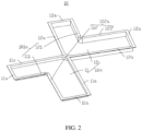
FIG. 2 is a schematic structural diagram of a housing according to some embodiments of this application. -
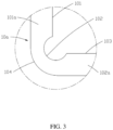
FIG. 3 is a schematic structural diagram of a sealed part at an inner corner of position III inFIG. 1 according to some embodiments of this application. -
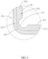
FIG. 4 is a schematic structural diagram of a sealed part according to some other embodiments of this application. -
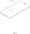
FIG. 5 is a schematic structural diagram of an electric device according to some embodiments of this application. -
Electrochemical apparatus 100 Housing 10 Main body part 10a Sealed part 10b First folded edge part 101a Second folded edge part 102a First outer edge 101 Outer arc edge 102 Second outer edge 103 Inner arc edge 104 First shell 11 Second shell 12 First extension part 11a First extension section 111 Third extension section 112 Second extension part 12a Second extension section 121 Fourth extension section 122 Sealed area 1011 Unsealed area 1012 Tab assembly 20 First tab 21 Second tab 22 - This application will be further described with reference to the accompanying drawings in the following specific embodiments.
- The following describes the technical solutions in some embodiments of this application with reference to the accompanying drawings in these embodiments of this application. Apparently, the described embodiments are only some rather than all of the embodiments of this application.
- When one component is assumed as being "disposed on/in" another component, the component may be provided directly on/in the another component or with a component possibly present therebetween. When one component is assumed as being "connected to" another component, it may be connected to the another component directly or with a component possibly present therebetween.
- Unless otherwise defined, all technical and scientific terms used herein shall have the same meanings as commonly understood by those skilled in the art to which this application pertains. The terms used herein in the specification of this application are for description of specific embodiments only without any intention to limit this application. The term "or/and" used herein includes any and all combinations of one or more associated items listed.
- An embodiment of this application provides an electrochemical apparatus including a housing. The housing includes a main body part and a sealed part extending outward from an edge of the main body part. The main body part is configured to accommodate an electrode assembly. The sealed part includes a first outer edge, an outer arc edge, and a second outer edge. The outer arc edge connects the first outer edge and the second outer edge. The outer arc edge protrudes toward the main body part. A minimum curvature radius of the outer arc edge is rmin mm, satisfying: rmin≥0.3. Setting the minimum curvature radius of the outer arc edge to be greater than or equal to 0.3 mm can reduce the stress concentration at the outer arc edge of the sealed part at an inner corner under drop conditions, thereby reducing the risk of tear and damage to the sealed part at the inner corner of a battery under drop conditions.
- The following describes in detail some embodiments of this application with reference to the accompanying drawings. Without conflict, the following embodiments and features in these embodiments may be combined with each other.
- Referring to
FIG. 1 , an embodiment of this application provides anelectrochemical apparatus 100 including ahousing 10, an electrode assembly (not shown in the figure), and atab assembly 20, where the electrode assembly is disposed inside thehousing 10, and thetab assembly 20 is connected to the electrode assembly and leads out of thehousing 10. - In some embodiments, the electrode assembly includes a wound structure formed by winding a positive electrode plate, a negative electrode plate, and a separator located between the positive electrode plate and the negative electrode plate. In some other embodiments, the electrode assembly may alternatively be of a laminated structure, that is, the electrode assembly is formed by sequentially stacking a plurality of positive electrode plates, separators, and negative electrode plates. In another embodiment, the electrode assembly includes the wound structure and the laminated structure. Optionally, the
housing 10 includes an aluminum-plastic film. - The
housing 10 includes amain body part 10a and a sealed part 10b extending outward from an edge of themain body part 10a, where themain body part 10a is used to accommodate the electrode assembly, and thetab assembly 20 extends out from the sealed part 10b. Optionally, a shape of thehousing 10 includes any one of L shape, V shape, U shape, or W shape. Optionally, thetab assembly 20 includes afirst tab 21 and asecond tab 22, where thefirst tab 21 and thesecond tab 22 have opposite polarities, and one of thefirst tab 21 and thesecond tab 22 is a positive electrode tab, and the other is a negative electrode tab. - In some embodiments, the
housing 10 includes a first layer, a metal layer, and a second layer that are stacked, where the metal layer is located between the first layer and the second layer, and the second layer is located at the outermost layer of the housing. The second layer may be a nylon layer or a composite layer of polyester resin (PET) and nylon, implementing protective functions of preventing pollution, resisting corrosion, and preventing damage caused by an external force. The metal layer may include one of aluminum or steel, implementing functions of waterproofing, blocking, and shaping the housing. The first layer is a heat sealing layer, and the first layer may include a polymer, where the polymer includes at least one of polypropylene or polyethylene. The first layer is used to seal thehousing 10 to form the sealed part 10b; and the first layer is used to separate the metal layer from the electrode assembly, reducing the risk of short circuit of the electrode assembly and electrolyte corrosion on the metal layer inside thehousing 10. - Referring to
FIG. 2 , in an embodiment, thehousing 10 includes afirst shell 11 and asecond shell 12, where thefirst shell 11 is connected to thesecond shell 12. Thefirst shell 11 and thesecond shell 12 can be snap-fitted along a connection position, allowing thefirst shell 11 and thesecond shell 12 to overlap to form themain body part 10a for covering the electrode assembly. A peripheral side of thefirst shell 11 extends outward to form a plurality offirst extension parts 11a, and a peripheral side of thesecond shell 12 extends outward to form a plurality ofsecond extension parts 12a. After thefirst shell 11 and thesecond shell 12 are snap-fitted along the connection position, thefirst extension parts 11a and thesecond extension parts 12a overlap and are hermetically connected to form the sealed part 10b. - Referring to
FIGs. 1 ,2 , and3 , the sealed part 10b includes a firstouter edge 101, anouter arc edge 102, and a secondouter edge 103, where theouter arc edge 102 is located between the firstouter edge 101 and the secondouter edge 103 and connects the firstouter edge 101 and the secondouter edge 103 to form an inner corner. Optionally, a shape of the inner corner includes any one of L shape, V shape, U shape, or W shape. Theouter arc edge 102 protrudes toward themain body part 10a, and a minimum curvature radius of theouter arc edge 102 is rmin mm, satisfying: rmin≥0.3. Limiting the minimum curvature radius of theouter arc edge 102 to be greater than or equal to 0.3 mm can reduce the stress concentration on the sealed part 10b at the inner corner under drop conditions, thereby reducing the risk of tear and damage to the sealed part 10b at the inner corner of the battery under drop conditions. In an embodiment, rmin≥0.5. In some embodiments, rmin is 0.3, 0.4, 0.5, 0.8, 1, 2, 3, 4, 5, 6, 7, 8, 9, or 10, or a range defined by any two of the foregoing values. - In an embodiment, rmin≤5. In this case, a small notch is present at the
outer arc edge 102, which can improve the sealing strength at the inner corner, thereby reducing the risk of tear and damage to the sealed part 10b at the inner corner of the battery under drop conditions. - In an embodiment, the sealed part 10b further includes an
inner arc edge 104, where theinner arc edge 104 protrudes toward themain body part 10a. A minimum curvature radius of theinner arc edge 104 is Rmin mm, satisfying: Rmin≥2. In this case, under drop conditions, when theinner arc edge 104 is impacted by the electrode assembly inside theelectrochemical apparatus 100, an impact force applied to this position can be dispersed, thereby reducing the risk of failure of the sealed part at the inner corner. In some embodiments, Rmin is 2, 3, 4, 5, 6, 7, 8, 9, or 10, or a range defined by any two of the foregoing values. - In an embodiment, a distance from a position with the minimum curvature radius of the
outer arc edge 102 to theinner arc edge 104 is Dmin mm, satisfying: Dmin×rmin≥0.1, where Dmin is a width between the position of the minimum curvature radius of theouter arc edge 102 and theinner arc edge 104. By satisfying the above relationship, a sealing width at the position of the minimum curvature radius of theouter arc edge 102 can match the stress applied to this position, which can reduce the risk of the position of the minimum curvature radius being completely torn, improving the sealing reliability of the electrochemical apparatus. In some embodiments, Dmin×rmin is 0.1, 0.2, 0.3, 0.4, 0.5, 0.6, 0.7, 0.8, 0.9, 1, 1.5, 2, 2.5, 3, 4, 5, or 6, or a range defined by any two of the foregoing values. - In an embodiment, Dmin≥1, which can increase the sealing width at the position of the minimum curvature radius of the
outer arc edge 102 at the inner corner, thereby increasing the sealing strength at this position and reducing the risk of failure of the sealed part 10b at the inner corner. - Referring to
FIGs. 2 and3 , optionally, when thefirst extension part 11a and thesecond extension part 12a are completely sealed, theinner arc edge 104 serves as the innermost arc edges of thefirst extension part 11a and thesecond extension part 12a. - Referring to
FIGs. 2 and4 , optionally, when thefirst extension part 11a and thesecond extension part 12a are partially sealed, thefirst extension part 11a and thesecond extension part 12a include a sealed area 1011 (that is, the sealed part 10b) and an unsealedarea 1012. The unsealedarea 1012 is a portion of themain body part 10a, and theinner arc edge 104 is an arc edge of a side of the sealedarea 1011 connected to the unsealedarea 1012. - Referring to
FIGs. 1 and2 , in an embodiment, the sealed part 10b includes a first foldededge part 101a and a second foldededge part 102a, where the firstouter edge 101 is provided on the first foldededge part 101a, and the secondouter edge 103 is provided on the second foldededge part 102a. The sealed part 10b is folded to form the first foldededge part 101a and the second foldededge part 102a, so that the first foldededge part 101a and the second foldededge part 102a abut against themain body part 10a. In this case, under drop conditions, when the first foldededge part 101a and the second foldededge part 102a are impacted, a tearing force applied to the sealed part 10b can be reduced, thereby reducing the risk of the firstouter edge 101 and the secondouter edge 103 being torn and improving the sealing reliability of the electrochemical apparatus. - Optionally, the
first extension part 11a includes afirst extension section 111, and thesecond extension part 12a includes asecond extension section 121. After thefirst shell 11 and thesecond shell 12 are snap-fitted along the connection position, thefirst extension section 111 and thesecond extension section 121 overlap and are hermetically connected, and are then bent to form the first foldededge part 101a. Optionally, thefirst extension part 11a further includes athird extension section 112, and thesecond extension part 12a further includes afourth extension section 122. After thefirst shell 11 and thesecond shell 12 are snap-fitted along the connection position, thethird extension section 112 and thefourth extension section 122 overlap and are hermetically connected, and are then bent to form the second foldededge part 102a. - In an embodiment, the first folded
edge part 101a extends along a first direction, the second foldededge part 102a extends along a second direction, and the first direction intersects with the second direction. Optionally, the first direction is perpendicular to the second direction. - Optionally, the first folded
edge part 101a includes a first folded portion and a second folded portion. The first folded portion and the second folded portion are formed by folding along a width direction of the first foldededge part 101a, and the second folded portion is connected to themain body part 10a and the first folded portion. When the first foldededge part 101a abuts against themain body part 10a, the second folded portion is located between the first folded portion and themain body part 10a. The provision of the first folded portion and the second folded portion can improve the sealing reliability of the first foldededge part 101a. - Optionally, the second folded
edge part 102a includes a third folded portion and a fourth folded portion. The third folded portion and the fourth folded portion are formed by folding along a width direction of the second foldededge part 102a, and the fourth folded portion is connected to themain body part 10a and the third folded portion. When the second foldededge part 102a abuts against themain body part 10a, the fourth folded portion is located between the third folded portion and themain body part 10a. The provision of the third folded portion and the fourth folded portion can improve the sealing reliability of the second foldededge part 102a. - The following will further described this application with reference to specific embodiments.
- L-shaped lithium-ion batteries, with different rmin values, Dmin×rmin values, and Dmin values, Rmin being 5 mm, and first outer edges and second outer edges being single folded edges, were subjected to drop test and hot box test.
- Drop test method: 10 lithium-ion batteries were taken and dropped freely from a height of 1.2 m and repeatedly dropped for 20 times, and the number of lithium-ion batteries with sealed parts torn at the inner corners after dropped (that is, the number of tears in drop test) and the number of lithium-ion batteries with sealed parts completely torn at the inner corners (that is, the number of sealing failures in drop test) were counted.
- Hot box test method: 10 lithium-ion batteries were taken and placed in an oven at 150°C for 30 minutes, and were observed to determine whether electrolyte leakage occurred at the sealed parts at the inner corners, and the number of batteries with electrolyte leakage was counted and served as the number of sealing failures in hot box test.
- The test data were shown in the following table.
rmin (mm) Dmin (mm) rmin×Dmin Number in test Number of tears in drop test Number of sealing failures in drop test Number of sealing failures in hot box test 0.1 0.2 0.02 10 7 5 10 0.1 0.5 0.05 10 7 3 6 0.1 1 0.1 10 8 0 0 0.1 2 0.2 10 6 0 0 0.1 3 0.3 10 7 0 0 0.3 0.2 0.06 10 3 2 9 0.3 0.5 0.15 10 4 0 6 0.3 1 0.3 10 3 0 0 0.3 2 0.6 10 3 0 0 0.3 3 0.9 10 2 0 0 0.5 0.2 0.1 10 0 0 9 0.5 0.5 0.25 10 0 0 4 0.5 1 0.5 10 0 0 0 0.5 2 1 10 0 0 0 0.5 3 1.5 10 0 0 0 1 0.2 0.2 10 0 0 10 1 0.5 0.5 10 0 0 5 1 1 1 10 0 0 0 1 2 2 10 0 0 0 1 3 3 10 0 0 0 2 0.2 0.4 10 0 0 10 2 0.5 1 10 0 0 6 2 1 2 10 0 0 0 2 2 4 10 0 0 0 2 3 6 10 0 0 0 - It can be seen from Table 1 that compared with the L-shaped lithium-ion batteries with rmin being 0.1 mm, the number of tears of the sealed parts at the inner corners of the L-shaped lithium-ion batteries with rmin≥0.3 mm in drop test is significantly reduced, especially when rmin≥0.5 mm, the number of tears of the sealed parts at the inner corners of the L-shaped lithium-ion batteries in the drop test is zero. This is because setting the minimum curvature radius of the outer arc edge to be greater than or equal to 0.3 mm can reduce the stress concentration at the outer arc edge of the sealed part under drop conditions, thereby reducing the risk of tear and damage to the sealed part of the battery under drop conditions, which otherwise causes safety accidents.
- Furthermore, when Dmin×rmin≥0.1, the number of the sealed parts completely torn at the inner corners of the L-shaped lithium-ion batteries in the drop test is zero. In this case, the sealing width at the position of the minimum curvature radius of the outer arc edge can match the stress applied to this position, which can reduce the risk of the position of the minimum curvature radius being completely torn, improving the sealing reliability of the battery.
- In addition, when Dmin≥1 mm, the number of sealing failures of the L-shaped lithium-ion batteries in the hot box test is significantly reduced. This is because Dmin≥1 mm can increase the sealing width at the position of the minimum curvature radius of the outer arc edge at the inner corner, thereby increasing the sealing strength at this position and reducing the risk of failure of the sealed part at the inner corner
- Referring to
FIG. 5 , this application further provides anelectric device 200 using theelectrochemical apparatus 100 according to any one of the foregoing embodiments. In an embodiment, theelectric device 200 in this application may be but is not limited to a mobile phone, a drone, an electric vehicle, an electric motorcycle, an electric motor bicycle, an electric tool, or a large household battery. - Persons of ordinary skill in the art should appreciate that the foregoing embodiments are for description of this application only but not for limiting this application. Appropriate modifications and variations made to the foregoing embodiments without departing from the essential spirit and scope of this application all fall within the scope of this application.
Claims (10)
- An electrochemical apparatus, comprising:
a housing, comprising a main body part and a sealed part extending outward from an edge of the main body part, wherein the main body part is configured to accommodate an electrode assembly, and the sealed part comprises a first outer edge, an outer arc edge, and a second outer edge, the outer arc edge connecting the first outer edge and the second outer edge, the outer arc edge protruding toward the main body part, and a minimum curvature radius of the outer arc edge being rmin mm, satisfying: rmin≥0.3. - The electrochemical apparatus according to claim 1, wherein the sealed part further comprises an inner arc edge, the inner arc edge protrudes toward the main body part, and a distance from a position with the minimum curvature radius of the outer arc edge to the inner arc edge is Dmin mm, satisfying: Dmin×rmin≥0.1.
- The electrochemical apparatus according to claim 2, wherein Dmin≥1.
- The electrochemical apparatus according to claim 2, wherein a minimum curvature radius of the inner arc edge is Rmin mm, satisfying: Rmin≥2.
- The electrochemical apparatus according to claim 1, wherein the sealed part comprises a first folded edge part and a second folded edge part, the first outer edge is provided on the first folded edge part, and the second outer edge is provided on the second folded edge part.
- The electrochemical apparatus according to claim 5, wherein the first folded edge part extends along a first direction, the second folded edge part extends along a second direction, and the first direction intersects with the second direction.
- The electrochemical apparatus according to claim 5, wherein at least one of the following conditions is met:(a) the first folded edge part comprises a first folded portion and a second folded portion, and the second folded portion being located between the first folded portion and the main body part;(b) the second folded edge part comprises a third folded portion and a fourth folded portion, and the fourth folded portion being located between the third folded portion and the main body part.
- The electrochemical apparatus according to claim 1, wherein a shape of the housing comprises any one of L shape, V shape, U shape, or W shape.
- The electrochemical apparatus according to claim 1, wherein the electrode assembly comprises at least one of a wound structure or a laminated structure.
- An electric device, comprising the electrochemical apparatus according to any one of claims 1 to 9.
Applications Claiming Priority (1)
| Application Number | Priority Date | Filing Date | Title |
|---|---|---|---|
| PCT/CN2022/079347 WO2023164939A1 (en) | 2022-03-04 | 2022-03-04 | Electrochemical apparatus and electrical device |
Publications (2)
| Publication Number | Publication Date |
|---|---|
| EP4478499A1 true EP4478499A1 (en) | 2024-12-18 |
| EP4478499A4 EP4478499A4 (en) | 2025-08-06 |
Family
ID=87882704
Family Applications (1)
| Application Number | Title | Priority Date | Filing Date |
|---|---|---|---|
| EP22929382.4A Pending EP4478499A4 (en) | 2022-03-04 | 2022-03-04 | ELECTROCHEMICAL DEVICE AND ELECTRICAL DEVICE |
Country Status (6)
| Country | Link |
|---|---|
| US (1) | US20240429508A1 (en) |
| EP (1) | EP4478499A4 (en) |
| JP (1) | JP7819333B2 (en) |
| KR (1) | KR20240151247A (en) |
| CN (1) | CN116848710A (en) |
| WO (1) | WO2023164939A1 (en) |
Families Citing this family (1)
| Publication number | Priority date | Publication date | Assignee | Title |
|---|---|---|---|---|
| CN120826816A (en) * | 2023-12-29 | 2025-10-21 | 东莞新能源科技有限公司 | Secondary batteries and electronic devices |
Family Cites Families (10)
| Publication number | Priority date | Publication date | Assignee | Title |
|---|---|---|---|---|
| KR101403388B1 (en) * | 2012-05-07 | 2014-06-03 | 주식회사 엘지화학 | Battery Cell of Irregular Structure and Battery Module Employed with the Same |
| US20170092923A1 (en) * | 2015-09-29 | 2017-03-30 | Apple Inc. | Battery cells having notched electrodes |
| KR101950464B1 (en) * | 2015-11-30 | 2019-02-20 | 주식회사 엘지화학 | Battery Cell of Irregular Structure with Improved Sealing Reliability of Cell Case |
| KR102566302B1 (en) * | 2016-06-27 | 2023-08-11 | 삼성에스디아이 주식회사 | Secondary battery |
| US11404682B2 (en) * | 2017-07-05 | 2022-08-02 | Apple Inc. | Non-rectangular shaped electrodes utilizing complex shaped insulation |
| US11114697B2 (en) * | 2018-09-04 | 2021-09-07 | Apple Inc. | Configurations for battery cell packaging |
| CN109697312B (en) * | 2018-12-18 | 2023-06-06 | 中航沈飞民用飞机有限责任公司 | Composite material opening analysis method considering BVID impact damage influence |
| CN109873092B (en) * | 2019-02-26 | 2020-10-23 | 宁德新能源科技有限公司 | Battery unit and electronic device |
| CN109904355A (en) * | 2019-03-08 | 2019-06-18 | 易佰特新能源科技有限公司 | A kind of Special-shaped lithium ion battery and its manufacturing method |
| CN111261826B (en) * | 2020-03-25 | 2023-01-10 | 宁德新能源科技有限公司 | Electrode assembly, battery using same and electric device |
-
2022
- 2022-03-04 JP JP2024548582A patent/JP7819333B2/en active Active
- 2022-03-04 EP EP22929382.4A patent/EP4478499A4/en active Pending
- 2022-03-04 WO PCT/CN2022/079347 patent/WO2023164939A1/en not_active Ceased
- 2022-03-04 CN CN202280010430.4A patent/CN116848710A/en active Pending
- 2022-03-04 KR KR1020247032602A patent/KR20240151247A/en active Pending
-
2024
- 2024-09-04 US US18/824,022 patent/US20240429508A1/en active Pending
Also Published As
| Publication number | Publication date |
|---|---|
| JP7819333B2 (en) | 2026-02-24 |
| US20240429508A1 (en) | 2024-12-26 |
| EP4478499A4 (en) | 2025-08-06 |
| JP2025505796A (en) | 2025-02-28 |
| WO2023164939A1 (en) | 2023-09-07 |
| CN116848710A (en) | 2023-10-03 |
| KR20240151247A (en) | 2024-10-17 |
Similar Documents
| Publication | Publication Date | Title |
|---|---|---|
| EP2184796B1 (en) | Electric energy storage device and its manufacturing method | |
| US7722984B2 (en) | Reinforced pouch type secondary battery | |
| US9099691B2 (en) | Rechargeable battery | |
| US20210126325A1 (en) | Secondary battery, apparatus and manufacturing method for secondary battery | |
| US20240030567A1 (en) | Battery and electric apparatus | |
| US20240014484A1 (en) | Electrochemical apparatus, preparation method thereof, and electronic apparatus | |
| US20220102824A1 (en) | Top cap assembly, secondary battery, battery module and device | |
| EP3993144A2 (en) | Power storage cell and method of manufacturing same | |
| CN115663404A (en) | Cells and Batteries | |
| EP4307415A1 (en) | Battery cell and electrical device | |
| US20230020115A1 (en) | Electrochemical apparatus and electronic apparatus | |
| US20240429508A1 (en) | Electrochemical apparatus and electric device | |
| KR102956955B1 (en) | Battery cell including electrode tabs on which stress relief portions are formed | |
| JP6930673B2 (en) | Manufacturing method of power storage device, electric vehicle and power storage device | |
| EP4131557A1 (en) | Electrochemical apparatus and electronic apparatus using electrochemical apparatus | |
| US20240243338A1 (en) | Battery and electronic device containing same | |
| JP5676095B2 (en) | Multilayer secondary battery | |
| US20130029208A1 (en) | Rechargeable battery | |
| EP4625640A1 (en) | Secondary battery | |
| EP4525147A2 (en) | Secondary battery and electronic apparatus | |
| EP4439806A1 (en) | Aluminum laminated film for battery, battery, and vehicle | |
| CN219892359U (en) | Battery and electronic equipment | |
| CN223092988U (en) | Battery and electronic equipment | |
| CN222546494U (en) | Cells and lithium-ion batteries | |
| KR20250064573A (en) | Battery |
Legal Events
| Date | Code | Title | Description |
|---|---|---|---|
| STAA | Information on the status of an ep patent application or granted ep patent |
Free format text: STATUS: THE INTERNATIONAL PUBLICATION HAS BEEN MADE |
|
| PUAI | Public reference made under article 153(3) epc to a published international application that has entered the european phase |
Free format text: ORIGINAL CODE: 0009012 |
|
| STAA | Information on the status of an ep patent application or granted ep patent |
Free format text: STATUS: REQUEST FOR EXAMINATION WAS MADE |
|
| 17P | Request for examination filed |
Effective date: 20240911 |
|
| AK | Designated contracting states |
Kind code of ref document: A1 Designated state(s): AL AT BE BG CH CY CZ DE DK EE ES FI FR GB GR HR HU IE IS IT LI LT LU LV MC MK MT NL NO PL PT RO RS SE SI SK SM TR |
|
| DAV | Request for validation of the european patent (deleted) | ||
| DAX | Request for extension of the european patent (deleted) | ||
| A4 | Supplementary search report drawn up and despatched |
Effective date: 20250704 |
|
| RIC1 | Information provided on ipc code assigned before grant |
Ipc: H01M 50/186 20210101AFI20250630BHEP Ipc: H01M 50/105 20210101ALI20250630BHEP Ipc: H01M 50/184 20210101ALI20250630BHEP |