EP2262033A1 - Electric storage device - Google Patents
Electric storage device Download PDFInfo
- Publication number
- EP2262033A1 EP2262033A1 EP10163072A EP10163072A EP2262033A1 EP 2262033 A1 EP2262033 A1 EP 2262033A1 EP 10163072 A EP10163072 A EP 10163072A EP 10163072 A EP10163072 A EP 10163072A EP 2262033 A1 EP2262033 A1 EP 2262033A1
- Authority
- EP
- European Patent Office
- Prior art keywords
- storage device
- safety valve
- electric storage
- valve portion
- sealing strip
- Prior art date
- Legal status (The legal status is an assumption and is not a legal conclusion. Google has not performed a legal analysis and makes no representation as to the accuracy of the status listed.)
- Withdrawn
Links
- 238000007789 sealing Methods 0.000 claims abstract description 67
- 239000003792 electrolyte Substances 0.000 claims abstract description 12
- 239000000463 material Substances 0.000 claims description 8
- 239000003960 organic solvent Substances 0.000 claims description 5
- 239000007772 electrode material Substances 0.000 abstract description 13
- 239000005001 laminate film Substances 0.000 description 27
- 239000008151 electrolyte solution Substances 0.000 description 15
- 239000010410 layer Substances 0.000 description 5
- HBBGRARXTFLTSG-UHFFFAOYSA-N Lithium ion Chemical compound [Li+] HBBGRARXTFLTSG-UHFFFAOYSA-N 0.000 description 4
- 229910001416 lithium ion Inorganic materials 0.000 description 4
- -1 polyethylene Polymers 0.000 description 4
- 230000005856 abnormality Effects 0.000 description 3
- 239000002985 plastic film Substances 0.000 description 3
- 229920006255 plastic film Polymers 0.000 description 3
- 239000004698 Polyethylene Substances 0.000 description 2
- 239000004743 Polypropylene Substances 0.000 description 2
- 239000003990 capacitor Substances 0.000 description 2
- 230000000694 effects Effects 0.000 description 2
- 229920000573 polyethylene Polymers 0.000 description 2
- 229920001155 polypropylene Polymers 0.000 description 2
- 239000000126 substance Substances 0.000 description 2
- KMTRUDSVKNLOMY-UHFFFAOYSA-N Ethylene carbonate Chemical compound O=C1OCCO1 KMTRUDSVKNLOMY-UHFFFAOYSA-N 0.000 description 1
- 239000000853 adhesive Substances 0.000 description 1
- 230000001070 adhesive effect Effects 0.000 description 1
- 229910052782 aluminium Inorganic materials 0.000 description 1
- XAGFODPZIPBFFR-UHFFFAOYSA-N aluminium Chemical compound [Al] XAGFODPZIPBFFR-UHFFFAOYSA-N 0.000 description 1
- 239000011888 foil Substances 0.000 description 1
- 239000007789 gas Substances 0.000 description 1
- 238000010030 laminating Methods 0.000 description 1
- 229910003002 lithium salt Inorganic materials 0.000 description 1
- 159000000002 lithium salts Chemical class 0.000 description 1
- 238000004519 manufacturing process Methods 0.000 description 1
- 229910052751 metal Inorganic materials 0.000 description 1
- 239000002184 metal Substances 0.000 description 1
- 238000000034 method Methods 0.000 description 1
- 238000012986 modification Methods 0.000 description 1
- 230000004048 modification Effects 0.000 description 1
- 229920006284 nylon film Polymers 0.000 description 1
- RUOJZAUFBMNUDX-UHFFFAOYSA-N propylene carbonate Chemical compound CC1COC(=O)O1 RUOJZAUFBMNUDX-UHFFFAOYSA-N 0.000 description 1
- 230000009467 reduction Effects 0.000 description 1
- 239000002356 single layer Substances 0.000 description 1
Images


Classifications
-
- H—ELECTRICITY
- H01—ELECTRIC ELEMENTS
- H01M—PROCESSES OR MEANS, e.g. BATTERIES, FOR THE DIRECT CONVERSION OF CHEMICAL ENERGY INTO ELECTRICAL ENERGY
- H01M50/00—Constructional details or processes of manufacture of the non-active parts of electrochemical cells other than fuel cells, e.g. hybrid cells
- H01M50/30—Arrangements for facilitating escape of gases
- H01M50/342—Non-re-sealable arrangements
- H01M50/3425—Non-re-sealable arrangements in the form of rupturable membranes or weakened parts, e.g. pierced with the aid of a sharp member
-
- B—PERFORMING OPERATIONS; TRANSPORTING
- B60—VEHICLES IN GENERAL
- B60L—PROPULSION OF ELECTRICALLY-PROPELLED VEHICLES; SUPPLYING ELECTRIC POWER FOR AUXILIARY EQUIPMENT OF ELECTRICALLY-PROPELLED VEHICLES; ELECTRODYNAMIC BRAKE SYSTEMS FOR VEHICLES IN GENERAL; MAGNETIC SUSPENSION OR LEVITATION FOR VEHICLES; MONITORING OPERATING VARIABLES OF ELECTRICALLY-PROPELLED VEHICLES; ELECTRIC SAFETY DEVICES FOR ELECTRICALLY-PROPELLED VEHICLES
- B60L50/00—Electric propulsion with power supplied within the vehicle
- B60L50/50—Electric propulsion with power supplied within the vehicle using propulsion power supplied by batteries or fuel cells
-
- H—ELECTRICITY
- H01—ELECTRIC ELEMENTS
- H01G—CAPACITORS; CAPACITORS, RECTIFIERS, DETECTORS, SWITCHING DEVICES, LIGHT-SENSITIVE OR TEMPERATURE-SENSITIVE DEVICES OF THE ELECTROLYTIC TYPE
- H01G9/00—Electrolytic capacitors, rectifiers, detectors, switching devices, light-sensitive or temperature-sensitive devices; Processes of their manufacture
- H01G9/004—Details
-
- H—ELECTRICITY
- H01—ELECTRIC ELEMENTS
- H01M—PROCESSES OR MEANS, e.g. BATTERIES, FOR THE DIRECT CONVERSION OF CHEMICAL ENERGY INTO ELECTRICAL ENERGY
- H01M50/00—Constructional details or processes of manufacture of the non-active parts of electrochemical cells other than fuel cells, e.g. hybrid cells
- H01M50/20—Mountings; Secondary casings or frames; Racks, modules or packs; Suspension devices; Shock absorbers; Transport or carrying devices; Holders
-
- H—ELECTRICITY
- H01—ELECTRIC ELEMENTS
- H01M—PROCESSES OR MEANS, e.g. BATTERIES, FOR THE DIRECT CONVERSION OF CHEMICAL ENERGY INTO ELECTRICAL ENERGY
- H01M50/00—Constructional details or processes of manufacture of the non-active parts of electrochemical cells other than fuel cells, e.g. hybrid cells
- H01M50/10—Primary casings; Jackets or wrappings
- H01M50/102—Primary casings; Jackets or wrappings characterised by their shape or physical structure
- H01M50/105—Pouches or flexible bags
-
- H—ELECTRICITY
- H01—ELECTRIC ELEMENTS
- H01M—PROCESSES OR MEANS, e.g. BATTERIES, FOR THE DIRECT CONVERSION OF CHEMICAL ENERGY INTO ELECTRICAL ENERGY
- H01M50/00—Constructional details or processes of manufacture of the non-active parts of electrochemical cells other than fuel cells, e.g. hybrid cells
- H01M50/50—Current conducting connections for cells or batteries
- H01M50/543—Terminals
- H01M50/547—Terminals characterised by the disposition of the terminals on the cells
- H01M50/548—Terminals characterised by the disposition of the terminals on the cells on opposite sides of the cell
-
- H—ELECTRICITY
- H01—ELECTRIC ELEMENTS
- H01M—PROCESSES OR MEANS, e.g. BATTERIES, FOR THE DIRECT CONVERSION OF CHEMICAL ENERGY INTO ELECTRICAL ENERGY
- H01M50/00—Constructional details or processes of manufacture of the non-active parts of electrochemical cells other than fuel cells, e.g. hybrid cells
- H01M50/50—Current conducting connections for cells or batteries
- H01M50/543—Terminals
- H01M50/552—Terminals characterised by their shape
- H01M50/553—Terminals adapted for prismatic, pouch or rectangular cells
- H01M50/557—Plate-shaped terminals
-
- Y—GENERAL TAGGING OF NEW TECHNOLOGICAL DEVELOPMENTS; GENERAL TAGGING OF CROSS-SECTIONAL TECHNOLOGIES SPANNING OVER SEVERAL SECTIONS OF THE IPC; TECHNICAL SUBJECTS COVERED BY FORMER USPC CROSS-REFERENCE ART COLLECTIONS [XRACs] AND DIGESTS
- Y02—TECHNOLOGIES OR APPLICATIONS FOR MITIGATION OR ADAPTATION AGAINST CLIMATE CHANGE
- Y02E—REDUCTION OF GREENHOUSE GAS [GHG] EMISSIONS, RELATED TO ENERGY GENERATION, TRANSMISSION OR DISTRIBUTION
- Y02E60/00—Enabling technologies; Technologies with a potential or indirect contribution to GHG emissions mitigation
- Y02E60/10—Energy storage using batteries
Definitions
- the present invention relates to an electric storage device including a film type container.
- Examples of an electric storage device to be installed in an electric vehicle or the like include a lithium ion secondary battery and a lithium ion capacitor.
- a lithium ion secondary battery When an abnormality such as overcharging, overdischarging, internal short-circuits or external short-circuits occurs in this type of electric storage device, an outer container may be swollen by gas generated from an electrolyte.
- a safety valve is attached to a metal can or the like constituting the outer container of the electric storage device so that when the internal pressure of the outer container rises, the safety valve is opened to release the gas.
- a film type container employing a laminate film has been proposed as an outer container of the electric storage device in order to achieve reductions in the size and weight of the electric storage device.
- a safety valve it is difficult to attach a safety valve to a film type container, and therefore electric storage devices in which a weakened portion such as a groove or a notch is formed in the film type container have been proposed (see Japanese Unexamined Patent Application Publications JP-A-1999-312 505 , JP-A-2003-297 322 , and JP-A-2000-100 399 , for example).
- the gas when the internal pressure of the container rises due to gas generation, the gas can be released by opening the weakened portion, and in so doing, rupturing and so on of the outer container can be forestalled.
- the outer container is simply formed with the weakened portion, and therefore, when the internal pressure of the outer container rises such that the weakened portion is opened, electrode material, electrolyte solution, and so on may be released out together with the gas.
- An object of the present invention is to improve the safety of an electric storage device by suppressing the release of electrode material, electrolyte solution, and so on.
- An electric storage device includes a film type container formed by adhering film materials to each other, and an electrode unit housed in an electrode housing portion of the film type container, wherein a first sealing strip that defines the electrode housing portion is formed on the film type container, a part of the first sealing strip being formed as a safety valve portion having a lower sealing strength than another site thereof, and a second sealing strip that opposes the safety valve portion at a predetermined distance and defines with the first sealing strip a discharge flow passage is formed on the film type container.
- the electrolyte housed in the film type container contains an organic solvent.
- an end portion of the discharge flow passage is open.
- an end portion of the discharge flow passage is sealed and a through hole is formed in the film materials on the discharge flow passage.
- the second sealing strip is provided opposite to the safety valve portion, and therefore an electrode material, an electrolyte solution, and so on discharged from the safety valve portion can impinge on the second sealing strip.
- the electrode material, the electrolyte solution, and so on can be trapped by the second sealing strip, and as a result, the release of the electrode material and electrolyte solution can be suppressed, thereby enabling an improvement in the safety of the electric storage device.
- Fig. 1 is a perspective view showing an electric storage device 10 according to an embodiment of the present invention.
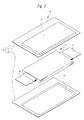
- Fig. 2 is an exploded perspective view showing the structure of the electric storage device 10.
- the electric storage device 10 includes an outer container (a film type container) 12 housing an electrode unit 11.
- the outer container 12 is formed by adhering a pair of laminate films (film materials) 13 to each other.
- the laminate film 13 has a laminated structure in which a plastic film is laminated onto either side of a sheet of aluminum foil.
- a material that exhibits superior mechanical strength and thermal resistance, such as a nylon film, is used for the plastic film constituting an outer layer of the laminate film 13.
- a material that is highly moisture-proof and exhibits a superior sealing property such as polyethylene or polypropylene, is used for the plastic film constituting an inner layer of the laminate film 13.
- Polyethylene and polypropylene can be adhered easily when heated. Therefore, by implementing heat sealing processing on the laminate films 13 overlapped such that the respective inner layers thereof face each other, the laminate films 13 can be joined to each other to form the outer container 12.
- the electrode unit 11 housed in the outer container 12 is constituted by a positive electrode and a negative electrode laminated alternately via a separator. Further, an electrolyte containing an organic solvent such as ethylene carbonate or propylene carbonate is injected into the outer container 12.
- a positive electrode terminal 14 that projects from an adhered surface of the laminate film 13 is joined to the positive electrode
- a negative electrode terminal 15 that projects from the adhered surface of the laminate film 13 is joined to the negative electrode.
- the present invention is not limited thereto, and a wound electrode unit in which an elongated positive electrode and an elongated negative electrode are overlapped and wound may be used instead.
- Fig. 3 is an illustrative view showing the outer container 12 in a sealed state. Sites indicated by shading in Fig. 3 correspond to sites that are sealed by heat sealing processing.
- the pair of laminate films 13 are aligned so as to sandwich the electrode unit 11. Heat sealing processing is then implemented on a lower portion and side portions of the laminate films 13 such that a substantially U-shaped sealing strip 20 is formed from the lower portion to the two side portions.
- the electrolyte is injected into the laminate films 13, which are formed into a bag shape by the sealing strip 20, whereupon heat sealing processing is implemented on an upper portion of the laminate films 13.
- heat sealing processing is implemented on an upper portion of the laminate films 13.
- two sealing strips 21 and 22 are formed on the upper portion of the laminate films 13.
- an electrode housing portion 23 housing the electrode unit 11 is defined by the first sealing strips 20 and 21. Further, a safety valve portion 21 a is formed substantially in the center of the sealing strip 21 with a heat seal width narrower than the other sites.
- a sealing strength of the safety valve portion 21a is designed to be lower than the sealing strength of the other portions of the sealing strips 20 and 21.
- the second sealing strip 22 is formed on the laminate films 13 to oppose the safety valve portion 21a at a predetermined distance.
- a discharge flow passage 24 is defined between the sealing strips 21 and the sealing strip 22, which is substantially parallel to the sealing strip 21, by the sealing strips 21 and 22. Note that an end portion 25 of the discharge flow passage 24 is open.
- Fig. 4A is an illustrative view showing a gas discharge route when the safety valve portion 21a is operated
- Fig. 4B is a perspective view showing the electric storage device 10 when the safety valve portion 21a is operated.
- the electrolyte employed in a lithium ion secondary battery, a lithium ion capacitor, and so on is often an organic solvent electrolyte formed by dissolving lithium salt in a combustible organic solvent, and there is therefore a need and demand for a structure that prevents the electrolyte from being released to the outside.
- the sealing strip 22 is provided opposite the safety valve portion 21a at the predetermined distance.
- housed substances electrolyte solution, gas, and so on
- gas G can be separated from housed substances including electrolyte solution X and so on.
- a flow direction of the separated gas G is then altered such that the gas G is guided to the discharge flow passage 24 and discharged to the outside from the open end portion 25 of the discharge flow passage 24.
- the sealing strip 22 opposite the safety valve portion 21a the electrode material, the electrolyte solution X, and so on can be trapped, and therefore the release of the electrode material, the electrolyte solution X, and so on can be suppressed.
- the safety of the electric storage device 10 can be increased.
- the increase in safety can be achieved simply by modifying a heat sealing pattern on the laminate films 13 to form the safety valve portion 21 a and the sealing strip 22, and therefore the cost of the improved-safety electric storage device 10 can be suppressed.
- Fig. 5 is an illustrative view showing an outer container (a film type container) 31 of an electric storage device 30 in a sealed state according to another embodiment of the present invention. Note that identical reference symbols have been allocated to members (constitutional parts) that are identical to the members (constitutional parts) shown in Fig. 3 , and description thereof has been omitted.
- a second sealing strip 32 provided on the upper portion of the laminate films 13 is formed to be shorter than the sealing strip 22 described above. Even when the sealing strip 32 is made shorter, identical effects to those described above can be obtained as long as a width dimension W2 of the sealing strip 32 is made longer than a width dimension W1 of the safety valve portion 21a and the sealing strip 32 is disposed opposite the safety valve portion 21a,
- the sealing strip 32 is structured to cover an opening range of the safety valve portion 21a, the electrode material, electrolyte solution, and so on can be trapped by the safety strip 32, and therefore identical effects to those described above can be obtained.
- Fig. 6A is an illustrative view showing an outer container (a film type container) 41 of an electric storage device 40 in a sealed state according to another embodiment of the present invention
- Fig. 6B is a perspective view showing the electric storage device 40 when the safety valve portion 21 a is operated.
- the through holes 43 are formed on the outside of the opening range of the safety valve portion 21a. As shown in Fig. 6B , when an abnormality occurs such that the safety valve portion 21 a opens, the gas G is guided through the discharge flow passage 24 to the through holes 43 and discharged in a thickness direction of the electric storage device 40.
- the electrode material, the electrolyte solution, and so on can be trapped not only by the sealing strip 22 but also by the end portion 42 of the discharge flow passage 24, and therefore the release of the electrolyte solution and so on can be greatly restricted.
- the present invention was described in detail above on the basis of the drawings, but the present invention is not limited to the above embodiments and may be subjected to various modifications within a scope that does not depart from the spirit thereof.
- the outer container 12 of the electric storage device 10 shown in Fig. 3 is structured such that the end portion 25 of the discharge flow passage 24 is open.
- heat sealing processing may be implemented to close the end portion 25 of the discharge flow passage 24, similarly to the outer container 41 of the electric storage device 40 shown in Fig. 6 .
- the sealing strength of the end portion 25 must be set so that the end portion 25 of the discharge flow passage 24 is peeled away by a pressure equal to that applied to the safety valve portion 21 a.
- the outer container 41 of the electric storage device 40 shown in Fig. 6 is structured such that the end portion 42 of the discharge flow passage 24 is closed. However, the end portion 42 of the discharge flow passage 24 may be opened, similarly to the outer container 12 of the electric storage device 10 shown in Fig. 3 .
- the through holes 43 are simply formed in the laminate films 13, but heat sealing processing may be implemented to close an edge portion of the through holes 43.
- the sealing strength of the edge portion of the through holes 43 must be set so that the edge portion is peeled away by a pressure equal to that applied to the safety valve portion 21 a.
- the outer containers 12, 31 and 41 are formed by laminating the pair of laminate films 13, but an outer container may be formed by folding back one sheet of laminate film.
- the sealing strips 20 to 22 and 32 and the safety valve portion 21 a are formed on the outer containers 12, 31 and 41 by implementing heat sealing processing on the laminate films 13, but the present invention is not limited thereto, and the sealing strips 20 to 22 and 32 and the safety valve portion 21 a may be formed on the outer containers 12, 31 and 41 by applying an adhesive to the laminate films 13 in a predetermined pattern.
- the laminate films 13 having a three-layer structure are used as the film material constituting the outer containers 12, 31 and 41, but the present invention is not limited thereto, and laminate films having a structure other than a three-layer structure, such as a single-layer structure, may be used instead.
Landscapes
- Chemical Kinetics & Catalysis (AREA)
- Electrochemistry (AREA)
- General Chemical & Material Sciences (AREA)
- Chemical & Material Sciences (AREA)
- Engineering & Computer Science (AREA)
- Power Engineering (AREA)
- Life Sciences & Earth Sciences (AREA)
- Sustainable Energy (AREA)
- Sustainable Development (AREA)
- Transportation (AREA)
- Mechanical Engineering (AREA)
- Microelectronics & Electronic Packaging (AREA)
- Gas Exhaust Devices For Batteries (AREA)
- Electric Double-Layer Capacitors Or The Like (AREA)
- Sealing Battery Cases Or Jackets (AREA)
- Secondary Cells (AREA)
Abstract
Sealing strips (20 and 21) are formed on an outer container (12) of an electric storage device (10) by heat sealing processing so as to surround an electrode housing portion (23). Further, a safety valve portion (21a) having a narrower sealing width than other sites is formed in the center of the sealing strip (21). Furthermore, a sealing strip (22) is formed on the outer container (12) to oppose the safety valve portion (21a) at a predetermined distance. When an internal pressure of the electrode housing portion (23) exceeds a prescribed value due to overcharge, etc., a sealing surface of the safety valve portion (21a) peels away, thereby opening the safety valve portion (21a) such that gas (G) in the electrode housing portion is discharged from the opened safety valve portion (21a). Electrode material and an electrolyte (X) are also discharged, but trapped by the sealing strip (22).
Description
- The present invention relates to an electric storage device including a film type container.
- Examples of an electric storage device to be installed in an electric vehicle or the like include a lithium ion secondary battery and a lithium ion capacitor. When an abnormality such as overcharging, overdischarging, internal short-circuits or external short-circuits occurs in this type of electric storage device, an outer container may be swollen by gas generated from an electrolyte.
- Therefore, a safety valve is attached to a metal can or the like constituting the outer container of the electric storage device so that when the internal pressure of the outer container rises, the safety valve is opened to release the gas.
- Incidentally, a film type container employing a laminate film has been proposed as an outer container of the electric storage device in order to achieve reductions in the size and weight of the electric storage device. However, it is difficult to attach a safety valve to a film type container, and therefore electric storage devices in which a weakened portion such as a groove or a notch is formed in the film type container have been proposed (see Japanese Unexamined Patent Application Publications
JP-A-1999-312 505 JP-A-2003-297 322 JP-A-2000-100 399 - Hence, when the internal pressure of the container rises due to gas generation, the gas can be released by opening the weakened portion, and in so doing, rupturing and so on of the outer container can be forestalled.
- However, in the electric storage devices described in
JP-A-1999-312 505 JP-A-2003-297 322 JP-A-2000-100 399 - When the electrolyte and the like of the electric storage device are released out in this manner, the safety of the electric storage device deteriorates, and there is therefore a need and demand for a structure that prevents the release of the electrolyte and so on.
- An object of the present invention is to improve the safety of an electric storage device by suppressing the release of electrode material, electrolyte solution, and so on.
- An electric storage device according to the present invention includes a film type container formed by adhering film materials to each other, and an electrode unit housed in an electrode housing portion of the film type container, wherein a first sealing strip that defines the electrode housing portion is formed on the film type container, a part of the first sealing strip being formed as a safety valve portion having a lower sealing strength than another site thereof, and a second sealing strip that opposes the safety valve portion at a predetermined distance and defines with the first sealing strip a discharge flow passage is formed on the film type container.
- In a specific embodiment of the electric storage device according to the present invention, the electrolyte housed in the film type container contains an organic solvent.
- In a specific embodiment of the electric storage device according to the present invention, an end portion of the discharge flow passage is open.
- In a specific embodiment of the electric storage device according to the present invention, an end portion of the discharge flow passage is sealed and a through hole is formed in the film materials on the discharge flow passage.
- According to the present invention, the second sealing strip is provided opposite to the safety valve portion, and therefore an electrode material, an electrolyte solution, and so on discharged from the safety valve portion can impinge on the second sealing strip.
- Therefore, the electrode material, the electrolyte solution, and so on can be trapped by the second sealing strip, and as a result, the release of the electrode material and electrolyte solution can be suppressed, thereby enabling an improvement in the safety of the electric storage device.
-
- Fig. 1
- is a perspective view showing an electric storage device serving as an embodiment of the present invention;
- Fig. 2
- is an exploded perspective view showing the structure of the electric storage device;
- Fig. 3
- is an illustrative view showing an outer container in a sealed state;
- Fig. 4A
- is an illustrative view showing a gas discharge route when a safety valve portion is operated, and
- Fig. 4B
- is a perspective view showing the electric storage device when the safety valve portion is operated;
- Fig. 5
- is an illustrative view showing an outer container of an electric storage device according to another embodiment of the present invention in a sealed state; and
- Fig. 6A
- is an illustrative view showing an outer container of an electric storage device according to another embodiment of the present invention in a sealed state, and
- Fig. 6B
- is a perspective view showing the electric storage device when a safety valve portion is operated.
-
Fig. 1 is a perspective view showing anelectric storage device 10 according to an embodiment of the present invention.Fig. 2 is an exploded perspective view showing the structure of theelectric storage device 10. As shown inFigs. 1 and2 , theelectric storage device 10 includes an outer container (a film type container) 12 housing anelectrode unit 11. - The
outer container 12 is formed by adhering a pair of laminate films (film materials) 13 to each other. Thelaminate film 13 has a laminated structure in which a plastic film is laminated onto either side of a sheet of aluminum foil. A material that exhibits superior mechanical strength and thermal resistance, such as a nylon film, is used for the plastic film constituting an outer layer of thelaminate film 13. - Further, a material that is highly moisture-proof and exhibits a superior sealing property, such as polyethylene or polypropylene, is used for the plastic film constituting an inner layer of the
laminate film 13. - Polyethylene and polypropylene can be adhered easily when heated. Therefore, by implementing heat sealing processing on the
laminate films 13 overlapped such that the respective inner layers thereof face each other, thelaminate films 13 can be joined to each other to form theouter container 12. - The
electrode unit 11 housed in theouter container 12 is constituted by a positive electrode and a negative electrode laminated alternately via a separator. Further, an electrolyte containing an organic solvent such as ethylene carbonate or propylene carbonate is injected into theouter container 12. - Furthermore, a
positive electrode terminal 14 that projects from an adhered surface of thelaminate film 13 is joined to the positive electrode, and anegative electrode terminal 15 that projects from the adhered surface of thelaminate film 13 is joined to the negative electrode. - Although a laminated electrode unit is illustrated as the
electrode unit 11, the present invention is not limited thereto, and a wound electrode unit in which an elongated positive electrode and an elongated negative electrode are overlapped and wound may be used instead. -
Fig. 3 is an illustrative view showing theouter container 12 in a sealed state. Sites indicated by shading inFig. 3 correspond to sites that are sealed by heat sealing processing. During a manufacturing process of theelectric storage device 10, the pair oflaminate films 13 are aligned so as to sandwich theelectrode unit 11. Heat sealing processing is then implemented on a lower portion and side portions of thelaminate films 13 such that a substantially U-shapedsealing strip 20 is formed from the lower portion to the two side portions. - Next, the electrolyte is injected into the
laminate films 13, which are formed into a bag shape by thesealing strip 20, whereupon heat sealing processing is implemented on an upper portion of thelaminate films 13. In this heat sealing process, twosealing strips laminate films 13. - By implementing heat sealing processing on the
laminate films 13 in this manner, anelectrode housing portion 23 housing theelectrode unit 11 is defined by thefirst sealing strips safety valve portion 21 a is formed substantially in the center of thesealing strip 21 with a heat seal width narrower than the other sites. - In other words, a sealing strength of the
safety valve portion 21a is designed to be lower than the sealing strength of the other portions of thesealing strips second sealing strip 22 is formed on thelaminate films 13 to oppose thesafety valve portion 21a at a predetermined distance. - Furthermore, a
discharge flow passage 24 is defined between the sealing strips 21 and the sealingstrip 22, which is substantially parallel to the sealingstrip 21, by the sealing strips 21 and 22. Note that anend portion 25 of thedischarge flow passage 24 is open. -
Fig. 4A is an illustrative view showing a gas discharge route when thesafety valve portion 21a is operated, andFig. 4B is a perspective view showing theelectric storage device 10 when thesafety valve portion 21a is operated. When an abnormality such as an overcharge or an internal short-circuit occurs in theelectric storage device 10, the electrolyte decomposes such that gas is generated, and as a result, an internal pressure of theelectrode housing portion 23 rises. - As shown in
Figs. 4A and 4B , when the internal pressure of theelectrode housing portion 23 rises above a prescribed value, a sealing surface of thesafety valve portion 21a peels away. In other words, the gas can be discharged by opening thesafety valve portion 21a before the internal pressure of theelectrode housing portion 23 increases dramatically, and as a result, rupturing of theouter container 12 and so on can be forestalled. - Note that in the above description, the term "operated" is used in relation to the
safety valve portion 21a, but this term actually means that thesafety valve portion 21a "opens" when the internal pressure of theelectrode housing portion 23 rises such that the sealing surface of thesafety valve portion 21a peels away, - Incidentally, when the internal pressure of the
electrode housing portion 23 rises such that thesafety valve portion 21 a opens, an electrode material, an electrolyte solution, and so on are discharged from thesafety valve portion 21 a together with the gas. When an electrode material, an electrolyte solution, and so on are released out in this manner, the safety of theelectric storage device 10 deteriorates. - In particular, the electrolyte employed in a lithium ion secondary battery, a lithium ion capacitor, and so on is often an organic solvent electrolyte formed by dissolving lithium salt in a combustible organic solvent, and there is therefore a need and demand for a structure that prevents the electrolyte from being released to the outside.
- Hence, in the
outer container 12 of theelectric storage device 10 according to the present invention, the sealingstrip 22 is provided opposite thesafety valve portion 21a at the predetermined distance. By providing the sealingstrip 22, housed substances (electrode material, electrolyte solution, gas, and so on) discharged from thesafety valve portion 21a can be caused to impinge on the sealingstrip 22, as shown inFig. 4A , whereupon gas G can be separated from housed substances including electrolyte solution X and so on. - A flow direction of the separated gas G is then altered such that the gas G is guided to the
discharge flow passage 24 and discharged to the outside from theopen end portion 25 of thedischarge flow passage 24. Hence, by providing the sealingstrip 22 opposite thesafety valve portion 21a, the electrode material, the electrolyte solution X, and so on can be trapped, and therefore the release of the electrode material, the electrolyte solution X, and so on can be suppressed. - As a result, the safety of the
electric storage device 10 can be increased. Moreover, the increase in safety can be achieved simply by modifying a heat sealing pattern on thelaminate films 13 to form thesafety valve portion 21 a and the sealingstrip 22, and therefore the cost of the improved-safetyelectric storage device 10 can be suppressed. -
Fig. 5 is an illustrative view showing an outer container (a film type container) 31 of anelectric storage device 30 in a sealed state according to another embodiment of the present invention. Note that identical reference symbols have been allocated to members (constitutional parts) that are identical to the members (constitutional parts) shown inFig. 3 , and description thereof has been omitted. - As shown in
Fig. 5 , asecond sealing strip 32 provided on the upper portion of thelaminate films 13 is formed to be shorter than the sealingstrip 22 described above. Even when the sealingstrip 32 is made shorter, identical effects to those described above can be obtained as long as a width dimension W2 of the sealingstrip 32 is made longer than a width dimension W1 of thesafety valve portion 21a and the sealingstrip 32 is disposed opposite thesafety valve portion 21a, - In other words, as long as the sealing
strip 32 is structured to cover an opening range of thesafety valve portion 21a, the electrode material, electrolyte solution, and so on can be trapped by thesafety strip 32, and therefore identical effects to those described above can be obtained. -
Fig. 6A is an illustrative view showing an outer container (a film type container) 41 of anelectric storage device 40 in a sealed state according to another embodiment of the present invention, andFig. 6B is a perspective view showing theelectric storage device 40 when thesafety valve portion 21 a is operated. - Note that identical reference symbols have been allocated to members (constitutional parts) that are identical to the members (constitutional parts) shown in
Fig. 3 , and description thereof has been omitted. As shown inFig. 6A , anend portion 42 of thedischarge flow passage 24 is sealed by heat sealing processing, and throughholes 43 are formed in thelaminate films 13 on thedischarge flow passage 24. - Note that the through
holes 43 are formed on the outside of the opening range of thesafety valve portion 21a. As shown inFig. 6B , when an abnormality occurs such that thesafety valve portion 21 a opens, the gas G is guided through thedischarge flow passage 24 to the throughholes 43 and discharged in a thickness direction of theelectric storage device 40. - Hence, the electrode material, the electrolyte solution, and so on can be trapped not only by the sealing
strip 22 but also by theend portion 42 of thedischarge flow passage 24, and therefore the release of the electrolyte solution and so on can be greatly restricted. - The present invention was described in detail above on the basis of the drawings, but the present invention is not limited to the above embodiments and may be subjected to various modifications within a scope that does not depart from the spirit thereof. For example, the
outer container 12 of theelectric storage device 10 shown inFig. 3 is structured such that theend portion 25 of thedischarge flow passage 24 is open. - However, heat sealing processing may be implemented to close the
end portion 25 of thedischarge flow passage 24, similarly to the outer container 41 of theelectric storage device 40 shown inFig. 6 . In this case, the sealing strength of theend portion 25 must be set so that theend portion 25 of thedischarge flow passage 24 is peeled away by a pressure equal to that applied to thesafety valve portion 21 a. - Further, the outer container 41 of the
electric storage device 40 shown inFig. 6 is structured such that theend portion 42 of thedischarge flow passage 24 is closed. However, theend portion 42 of thedischarge flow passage 24 may be opened, similarly to theouter container 12 of theelectric storage device 10 shown inFig. 3 . - Moreover, in
Fig. 6 , the throughholes 43 are simply formed in thelaminate films 13, but heat sealing processing may be implemented to close an edge portion of the through holes 43. In this case, the sealing strength of the edge portion of the throughholes 43 must be set so that the edge portion is peeled away by a pressure equal to that applied to thesafety valve portion 21 a. - Furthermore, in the above description, the
outer containers 12, 31 and 41 are formed by laminating the pair oflaminate films 13, but an outer container may be formed by folding back one sheet of laminate film. - Moreover, in the above description, the sealing strips 20 to 22 and 32 and the
safety valve portion 21 a are formed on theouter containers 12, 31 and 41 by implementing heat sealing processing on thelaminate films 13, but the present invention is not limited thereto, and the sealing strips 20 to 22 and 32 and thesafety valve portion 21 a may be formed on theouter containers 12, 31 and 41 by applying an adhesive to thelaminate films 13 in a predetermined pattern. - Further, in the above description, the
laminate films 13 having a three-layer structure are used as the film material constituting theouter containers 12, 31 and 41, but the present invention is not limited thereto, and laminate films having a structure other than a three-layer structure, such as a single-layer structure, may be used instead. -
- 10
- electric storage device
- 11
- electrode unit
- 12
- outer container
- 13
- laminate film
- 14
- positive electrode terminal
- 15
- negative electrode terminal
- 20
- sealing strip
- 21
- sealing strip
- 21a
- safety valve portion
- 22
- sealing strip
- 23
- electrode housing portion
- 24
- discharge flow passage
- 25
- end portion
- 30
- electric storage device
- 31
- outer container
- 32
-
second sealing strip 32 - 40
- electric storage device
- 41
- outer container
- 42
- end portion
- 43
- through holes
- G
- gas
- X
- electrolyte solution
- W1
- width dimension
- W2
- width dimension
Claims (4)
- An electric storage device (10), comprising a film type container (12) formed by adhering film materials (13) to each other, and an electrode unit (11) housed in an electrode housing portion (23) of the film type container (12), wherein
a first sealing strip (20, 21) that defines the electrode housing portion (23) is formed on the film type container (12), a part of the first sealing strip (20, 21)being formed as a safety valve portion (21a)having a lower sealing strength than another site thereof, and
a second sealing strip (22) that opposes the safety valve portion (21a)via a predetermined interval and defines with the first sealing strip (20, 21) a discharge flow passage (24) is formed on the film type container (12). - The electric storage device (10) according to claim 1,
wherein an electrolyte (X) housed in the film type container (12) contains an organic solvent. - The electric storage device (10) according to claim 1 or 2,
wherein an end portion (25) of the discharge flow passage (24) is open. - The electric storage device (10) according to claim 1 or 2,
wherein an end portion (42) of the discharge flow passage (24) is sealed and a through hole(43) is formed in the film materials (13) on the discharge flow passage (24).
Applications Claiming Priority (1)
| Application Number | Priority Date | Filing Date | Title |
|---|---|---|---|
| JP2009120221A JP2010267593A (en) | 2009-05-18 | 2009-05-18 | Power storage device |
Publications (1)
| Publication Number | Publication Date |
|---|---|
| EP2262033A1 true EP2262033A1 (en) | 2010-12-15 |
Family
ID=42556662
Family Applications (1)
| Application Number | Title | Priority Date | Filing Date |
|---|---|---|---|
| EP10163072A Withdrawn EP2262033A1 (en) | 2009-05-18 | 2010-05-18 | Electric storage device |
Country Status (5)
| Country | Link |
|---|---|
| US (1) | US20100291423A1 (en) |
| EP (1) | EP2262033A1 (en) |
| JP (1) | JP2010267593A (en) |
| KR (1) | KR20100124209A (en) |
| CN (1) | CN101894970A (en) |
Cited By (1)
| Publication number | Priority date | Publication date | Assignee | Title |
|---|---|---|---|---|
| EP4120446A4 (en) * | 2020-11-09 | 2024-03-06 | LG Energy Solution, Ltd. | Secondary battery |
Families Citing this family (13)
| Publication number | Priority date | Publication date | Assignee | Title |
|---|---|---|---|---|
| JP5673135B2 (en) * | 2011-01-24 | 2015-02-18 | 日産自動車株式会社 | Laminated battery |
| JP5734076B2 (en) * | 2011-04-25 | 2015-06-10 | Jmエナジー株式会社 | Power storage device and power storage module |
| KR101271920B1 (en) * | 2011-06-17 | 2013-06-05 | 삼성에스디아이 주식회사 | Secondary battery |
| CN103077824A (en) * | 2013-01-09 | 2013-05-01 | 安徽精新能源科技股份有限公司 | Capacitor with adjustable internal pressure |
| US9735402B2 (en) * | 2013-07-30 | 2017-08-15 | Lg Chem, Ltd. | Battery cell having double sealing structure |
| KR20170070001A (en) * | 2014-08-08 | 2017-06-21 | 테크트로닉 인더스트리스 컴파니, 리미티드 | Battery pouch, battery cell and method of making a pouch or battery cell |
| CN208819975U (en) | 2018-02-27 | 2019-05-03 | 创科(澳门离岸商业服务)有限公司 | Soft-package battery with safety protection function |
| JP7154791B2 (en) | 2018-03-28 | 2022-10-18 | Fdk株式会社 | thin battery |
| JP6996422B2 (en) * | 2018-05-28 | 2022-02-21 | 大日本印刷株式会社 | battery |
| KR20210032219A (en) | 2019-09-16 | 2021-03-24 | 주식회사 엘지화학 | Rechargeable battery manufacturing method, rechargeable battery manufactured from thereof |
| JP7259691B2 (en) * | 2019-10-08 | 2023-04-18 | トヨタ自動車株式会社 | laminate structure |
| KR20210050748A (en) * | 2019-10-29 | 2021-05-10 | 에스케이이노베이션 주식회사 | Pouch-type secondary battery |
| WO2024136199A1 (en) * | 2022-12-23 | 2024-06-27 | 주식회사 엘지에너지솔루션 | Secondary battery |
Citations (5)
| Publication number | Priority date | Publication date | Assignee | Title |
|---|---|---|---|---|
| JPH11312505A (en) | 1998-04-28 | 1999-11-09 | Sony Corp | Thin battery |
| JP2000100399A (en) | 1998-09-21 | 2000-04-07 | Toshiba Battery Co Ltd | Manufacture of polymer lithium secondary battery |
| JP2003297322A (en) | 2002-03-28 | 2003-10-17 | Sanyo Electric Co Ltd | Battery |
| JP2006332009A (en) * | 2005-05-30 | 2006-12-07 | Dainippon Printing Co Ltd | Battery case |
| JP2008077945A (en) * | 2006-09-20 | 2008-04-03 | Dainippon Printing Co Ltd | Flat electrochemical cell |
Family Cites Families (8)
| Publication number | Priority date | Publication date | Assignee | Title |
|---|---|---|---|---|
| JPS59207558A (en) * | 1983-05-11 | 1984-11-24 | Matsushita Electric Ind Co Ltd | Manufacture of closed lead-acid battery |
| JPH0423055U (en) * | 1990-06-15 | 1992-02-25 | ||
| US6653018B2 (en) * | 2000-03-17 | 2003-11-25 | Tdk Corporation | Electrochemical device |
| JP4604441B2 (en) * | 2002-07-18 | 2011-01-05 | 日本電気株式会社 | Film-clad battery and manufacturing method thereof |
| KR20040017094A (en) * | 2002-08-20 | 2004-02-26 | 삼성에스디아이 주식회사 | Pouch type secondary battery with safty vent |
| JP4232038B2 (en) * | 2004-08-11 | 2009-03-04 | 日本電気株式会社 | Film-clad electrical device and method for manufacturing the same |
| JP2006092905A (en) * | 2004-09-24 | 2006-04-06 | Toyota Motor Corp | Laminated battery module |
| JP5059890B2 (en) * | 2009-03-31 | 2012-10-31 | Jmエナジー株式会社 | Laminate exterior power storage device |
-
2009
- 2009-05-18 JP JP2009120221A patent/JP2010267593A/en active Pending
-
2010
- 2010-05-11 KR KR1020100043922A patent/KR20100124209A/en not_active Application Discontinuation
- 2010-05-18 CN CN2010101778939A patent/CN101894970A/en active Pending
- 2010-05-18 US US12/782,131 patent/US20100291423A1/en not_active Abandoned
- 2010-05-18 EP EP10163072A patent/EP2262033A1/en not_active Withdrawn
Patent Citations (5)
| Publication number | Priority date | Publication date | Assignee | Title |
|---|---|---|---|---|
| JPH11312505A (en) | 1998-04-28 | 1999-11-09 | Sony Corp | Thin battery |
| JP2000100399A (en) | 1998-09-21 | 2000-04-07 | Toshiba Battery Co Ltd | Manufacture of polymer lithium secondary battery |
| JP2003297322A (en) | 2002-03-28 | 2003-10-17 | Sanyo Electric Co Ltd | Battery |
| JP2006332009A (en) * | 2005-05-30 | 2006-12-07 | Dainippon Printing Co Ltd | Battery case |
| JP2008077945A (en) * | 2006-09-20 | 2008-04-03 | Dainippon Printing Co Ltd | Flat electrochemical cell |
Cited By (1)
| Publication number | Priority date | Publication date | Assignee | Title |
|---|---|---|---|---|
| EP4120446A4 (en) * | 2020-11-09 | 2024-03-06 | LG Energy Solution, Ltd. | Secondary battery |
Also Published As
| Publication number | Publication date |
|---|---|
| US20100291423A1 (en) | 2010-11-18 |
| CN101894970A (en) | 2010-11-24 |
| KR20100124209A (en) | 2010-11-26 |
| JP2010267593A (en) | 2010-11-25 |
Similar Documents
| Publication | Publication Date | Title |
|---|---|---|
| EP2262033A1 (en) | Electric storage device | |
| CN106067525B (en) | Secondary battery and battery module having the same | |
| US7722984B2 (en) | Reinforced pouch type secondary battery | |
| JP5674936B2 (en) | Secondary battery pouch with improved safety, pouch-type secondary battery and medium-sized battery pack using the same | |
| EP3038184B1 (en) | Film-packaged electric device | |
| KR100900411B1 (en) | Secondary Battery Including One-way Exhaust Valve | |
| CN205752283U (en) | Electrical storage device exterior body and electrical storage device | |
| KR101216422B1 (en) | Secondary Battery Having Sealing Portion of Improved Insulating Property | |
| KR101508416B1 (en) | Pouch-type secondary battery | |
| US11245147B2 (en) | Pouch-type secondary battery having unsealed portion | |
| WO2005096412A1 (en) | Electrical device with film covering, frame member, and housing system for electrical device with film covering | |
| KR101229228B1 (en) | Secondary Battery with Improved Moisture Barrier | |
| TW201304950A (en) | Battery pouch sheet edge insulation | |
| KR20080022915A (en) | Pouch for secondary battery | |
| KR101811934B1 (en) | Safety-device-fitted electrochemical device and safety device for electrochemical device | |
| KR20210075476A (en) | Pouch-type Battery Cell Having Venting Part and Method for Preparing the Same | |
| KR102159368B1 (en) | A pouch for an electrochemical device | |
| KR102384912B1 (en) | Secondary battery and battery module having the same | |
| JP2004327047A (en) | Polymer battery and polymer battery pack | |
| KR101075349B1 (en) | Pouch type rechargeable battery | |
| JP6930673B2 (en) | Manufacturing method of power storage device, electric vehicle and power storage device | |
| KR20160055600A (en) | Pouch-typed secondary battery and process for preparing same | |
| WO2020246072A1 (en) | Electricity storage device, electricity storage device assembly, electric vehicle, and method for manufacturing electricity storage device | |
| KR20220067981A (en) | Exterior material for flaxible battery |
Legal Events
| Date | Code | Title | Description |
|---|---|---|---|
| PUAI | Public reference made under article 153(3) epc to a published international application that has entered the european phase |
Free format text: ORIGINAL CODE: 0009012 |
|
| AK | Designated contracting states |
Kind code of ref document: A1 Designated state(s): AL AT BE BG CH CY CZ DE DK EE ES FI FR GB GR HR HU IE IS IT LI LT LU LV MC MK MT NL NO PL PT RO SE SI SK SM TR |
|
| AX | Request for extension of the european patent |
Extension state: BA ME RS |
|
| 17P | Request for examination filed |
Effective date: 20110615 |
|
| 17Q | First examination report despatched |
Effective date: 20120626 |
|
| STAA | Information on the status of an ep patent application or granted ep patent |
Free format text: STATUS: THE APPLICATION HAS BEEN WITHDRAWN |
|
| 18W | Application withdrawn |
Effective date: 20121025 |