EP4478492A1 - Battery case, battery case molding device, and secondary battery manufacturing method - Google Patents
Battery case, battery case molding device, and secondary battery manufacturing method Download PDFInfo
- Publication number
- EP4478492A1 EP4478492A1 EP23753039.9A EP23753039A EP4478492A1 EP 4478492 A1 EP4478492 A1 EP 4478492A1 EP 23753039 A EP23753039 A EP 23753039A EP 4478492 A1 EP4478492 A1 EP 4478492A1
- Authority
- EP
- European Patent Office
- Prior art keywords
- case
- battery case
- insulation failure
- sealing
- preventing
- Prior art date
- Legal status (The legal status is an assumption and is not a legal conclusion. Google has not performed a legal analysis and makes no representation as to the accuracy of the status listed.)
- Pending
Links
Images




Classifications
-
- H—ELECTRICITY
- H01—ELECTRIC ELEMENTS
- H01M—PROCESSES OR MEANS, e.g. BATTERIES, FOR THE DIRECT CONVERSION OF CHEMICAL ENERGY INTO ELECTRICAL ENERGY
- H01M10/00—Secondary cells; Manufacture thereof
- H01M10/05—Accumulators with non-aqueous electrolyte
- H01M10/052—Li-accumulators
-
- H—ELECTRICITY
- H01—ELECTRIC ELEMENTS
- H01M—PROCESSES OR MEANS, e.g. BATTERIES, FOR THE DIRECT CONVERSION OF CHEMICAL ENERGY INTO ELECTRICAL ENERGY
- H01M50/00—Constructional details or processes of manufacture of the non-active parts of electrochemical cells other than fuel cells, e.g. hybrid cells
- H01M50/10—Primary casings; Jackets or wrappings
- H01M50/183—Sealing members
- H01M50/184—Sealing members characterised by their shape or structure
-
- B—PERFORMING OPERATIONS; TRANSPORTING
- B21—MECHANICAL METAL-WORKING WITHOUT ESSENTIALLY REMOVING MATERIAL; PUNCHING METAL
- B21D—WORKING OR PROCESSING OF SHEET METAL OR METAL TUBES, RODS OR PROFILES WITHOUT ESSENTIALLY REMOVING MATERIAL; PUNCHING METAL
- B21D45/00—Ejecting or stripping-off devices arranged in machines or tools dealt with in this subclass
- B21D45/06—Stripping-off devices
-
- B—PERFORMING OPERATIONS; TRANSPORTING
- B29—WORKING OF PLASTICS; WORKING OF SUBSTANCES IN A PLASTIC STATE IN GENERAL
- B29C—SHAPING OR JOINING OF PLASTICS; SHAPING OF MATERIAL IN A PLASTIC STATE, NOT OTHERWISE PROVIDED FOR; AFTER-TREATMENT OF THE SHAPED PRODUCTS, e.g. REPAIRING
- B29C43/00—Compression moulding, i.e. applying external pressure to flow the moulding material; Apparatus therefor
- B29C43/32—Component parts, details or accessories; Auxiliary operations
- B29C43/36—Moulds for making articles of definite length, i.e. discrete articles
-
- B—PERFORMING OPERATIONS; TRANSPORTING
- B29—WORKING OF PLASTICS; WORKING OF SUBSTANCES IN A PLASTIC STATE IN GENERAL
- B29C—SHAPING OR JOINING OF PLASTICS; SHAPING OF MATERIAL IN A PLASTIC STATE, NOT OTHERWISE PROVIDED FOR; AFTER-TREATMENT OF THE SHAPED PRODUCTS, e.g. REPAIRING
- B29C43/00—Compression moulding, i.e. applying external pressure to flow the moulding material; Apparatus therefor
- B29C43/32—Component parts, details or accessories; Auxiliary operations
- B29C43/36—Moulds for making articles of definite length, i.e. discrete articles
- B29C43/3607—Moulds for making articles of definite length, i.e. discrete articles with sealing means or the like
-
- B—PERFORMING OPERATIONS; TRANSPORTING
- B29—WORKING OF PLASTICS; WORKING OF SUBSTANCES IN A PLASTIC STATE IN GENERAL
- B29C—SHAPING OR JOINING OF PLASTICS; SHAPING OF MATERIAL IN A PLASTIC STATE, NOT OTHERWISE PROVIDED FOR; AFTER-TREATMENT OF THE SHAPED PRODUCTS, e.g. REPAIRING
- B29C51/00—Shaping by thermoforming, i.e. shaping sheets or sheet like preforms after heating, e.g. shaping sheets in matched moulds or by deep-drawing; Apparatus therefor
- B29C51/08—Deep drawing or matched-mould forming, i.e. using mechanical means only
-
- B—PERFORMING OPERATIONS; TRANSPORTING
- B29—WORKING OF PLASTICS; WORKING OF SUBSTANCES IN A PLASTIC STATE IN GENERAL
- B29C—SHAPING OR JOINING OF PLASTICS; SHAPING OF MATERIAL IN A PLASTIC STATE, NOT OTHERWISE PROVIDED FOR; AFTER-TREATMENT OF THE SHAPED PRODUCTS, e.g. REPAIRING
- B29C65/00—Joining or sealing of preformed parts, e.g. welding of plastics materials; Apparatus therefor
- B29C65/02—Joining or sealing of preformed parts, e.g. welding of plastics materials; Apparatus therefor by heating, with or without pressure
-
- B—PERFORMING OPERATIONS; TRANSPORTING
- B29—WORKING OF PLASTICS; WORKING OF SUBSTANCES IN A PLASTIC STATE IN GENERAL
- B29C—SHAPING OR JOINING OF PLASTICS; SHAPING OF MATERIAL IN A PLASTIC STATE, NOT OTHERWISE PROVIDED FOR; AFTER-TREATMENT OF THE SHAPED PRODUCTS, e.g. REPAIRING
- B29C66/00—General aspects of processes or apparatus for joining preformed parts
- B29C66/01—General aspects dealing with the joint area or with the area to be joined
- B29C66/02—Preparation of the material, in the area to be joined, prior to joining or welding
- B29C66/022—Mechanical pre-treatments, e.g. reshaping
- B29C66/0222—Mechanical pre-treatments, e.g. reshaping without removal of material, e.g. cleaning by air blowing or using brushes
-
- B—PERFORMING OPERATIONS; TRANSPORTING
- B29—WORKING OF PLASTICS; WORKING OF SUBSTANCES IN A PLASTIC STATE IN GENERAL
- B29C—SHAPING OR JOINING OF PLASTICS; SHAPING OF MATERIAL IN A PLASTIC STATE, NOT OTHERWISE PROVIDED FOR; AFTER-TREATMENT OF THE SHAPED PRODUCTS, e.g. REPAIRING
- B29C66/00—General aspects of processes or apparatus for joining preformed parts
- B29C66/01—General aspects dealing with the joint area or with the area to be joined
- B29C66/05—Particular design of joint configurations
- B29C66/10—Particular design of joint configurations particular design of the joint cross-sections
- B29C66/13—Single flanged joints; Fin-type joints; Single hem joints; Edge joints; Interpenetrating fingered joints; Other specific particular designs of joint cross-sections not provided for in groups B29C66/11 - B29C66/12
- B29C66/131—Single flanged joints, i.e. one of the parts to be joined being rigid and flanged in the joint area
- B29C66/1312—Single flange to flange joints, the parts to be joined being rigid
-
- B—PERFORMING OPERATIONS; TRANSPORTING
- B29—WORKING OF PLASTICS; WORKING OF SUBSTANCES IN A PLASTIC STATE IN GENERAL
- B29C—SHAPING OR JOINING OF PLASTICS; SHAPING OF MATERIAL IN A PLASTIC STATE, NOT OTHERWISE PROVIDED FOR; AFTER-TREATMENT OF THE SHAPED PRODUCTS, e.g. REPAIRING
- B29C66/00—General aspects of processes or apparatus for joining preformed parts
- B29C66/01—General aspects dealing with the joint area or with the area to be joined
- B29C66/32—Measures for keeping the burr form under control; Avoiding burr formation; Shaping the burr
- B29C66/322—Providing cavities in the joined article to collect the burr
-
- B—PERFORMING OPERATIONS; TRANSPORTING
- B29—WORKING OF PLASTICS; WORKING OF SUBSTANCES IN A PLASTIC STATE IN GENERAL
- B29C—SHAPING OR JOINING OF PLASTICS; SHAPING OF MATERIAL IN A PLASTIC STATE, NOT OTHERWISE PROVIDED FOR; AFTER-TREATMENT OF THE SHAPED PRODUCTS, e.g. REPAIRING
- B29C66/00—General aspects of processes or apparatus for joining preformed parts
- B29C66/01—General aspects dealing with the joint area or with the area to be joined
- B29C66/32—Measures for keeping the burr form under control; Avoiding burr formation; Shaping the burr
- B29C66/324—Avoiding burr formation
- B29C66/3242—Avoiding burr formation on the inside of a tubular or hollow article
-
- B—PERFORMING OPERATIONS; TRANSPORTING
- B29—WORKING OF PLASTICS; WORKING OF SUBSTANCES IN A PLASTIC STATE IN GENERAL
- B29C—SHAPING OR JOINING OF PLASTICS; SHAPING OF MATERIAL IN A PLASTIC STATE, NOT OTHERWISE PROVIDED FOR; AFTER-TREATMENT OF THE SHAPED PRODUCTS, e.g. REPAIRING
- B29C66/00—General aspects of processes or apparatus for joining preformed parts
- B29C66/40—General aspects of joining substantially flat articles, e.g. plates, sheets or web-like materials; Making flat seams in tubular or hollow articles; Joining single elements to substantially flat surfaces
- B29C66/41—Joining substantially flat articles ; Making flat seams in tubular or hollow articles
- B29C66/43—Joining a relatively small portion of the surface of said articles
- B29C66/433—Casing-in, i.e. enclosing an element between two sheets by an outlined seam
-
- B—PERFORMING OPERATIONS; TRANSPORTING
- B29—WORKING OF PLASTICS; WORKING OF SUBSTANCES IN A PLASTIC STATE IN GENERAL
- B29C—SHAPING OR JOINING OF PLASTICS; SHAPING OF MATERIAL IN A PLASTIC STATE, NOT OTHERWISE PROVIDED FOR; AFTER-TREATMENT OF THE SHAPED PRODUCTS, e.g. REPAIRING
- B29C66/00—General aspects of processes or apparatus for joining preformed parts
- B29C66/50—General aspects of joining tubular articles; General aspects of joining long products, i.e. bars or profiled elements; General aspects of joining single elements to tubular articles, hollow articles or bars; General aspects of joining several hollow-preforms to form hollow or tubular articles
- B29C66/51—Joining tubular articles, profiled elements or bars; Joining single elements to tubular articles, hollow articles or bars; Joining several hollow-preforms to form hollow or tubular articles
- B29C66/54—Joining several hollow-preforms, e.g. half-shells, to form hollow articles, e.g. for making balls, containers; Joining several hollow-preforms, e.g. half-cylinders, to form tubular articles
- B29C66/549—Joining several hollow-preforms, e.g. half-shells, to form hollow articles, e.g. for making balls, containers; Joining several hollow-preforms, e.g. half-cylinders, to form tubular articles said hollow-preforms being interconnected during their moulding process, e.g. by a hinge
-
- B—PERFORMING OPERATIONS; TRANSPORTING
- B29—WORKING OF PLASTICS; WORKING OF SUBSTANCES IN A PLASTIC STATE IN GENERAL
- B29C—SHAPING OR JOINING OF PLASTICS; SHAPING OF MATERIAL IN A PLASTIC STATE, NOT OTHERWISE PROVIDED FOR; AFTER-TREATMENT OF THE SHAPED PRODUCTS, e.g. REPAIRING
- B29C66/00—General aspects of processes or apparatus for joining preformed parts
- B29C66/70—General aspects of processes or apparatus for joining preformed parts characterised by the composition, physical properties or the structure of the material of the parts to be joined; Joining with non-plastics material
- B29C66/72—General aspects of processes or apparatus for joining preformed parts characterised by the composition, physical properties or the structure of the material of the parts to be joined; Joining with non-plastics material characterised by the structure of the material of the parts to be joined
- B29C66/723—General aspects of processes or apparatus for joining preformed parts characterised by the composition, physical properties or the structure of the material of the parts to be joined; Joining with non-plastics material characterised by the structure of the material of the parts to be joined being multi-layered
- B29C66/7232—General aspects of processes or apparatus for joining preformed parts characterised by the composition, physical properties or the structure of the material of the parts to be joined; Joining with non-plastics material characterised by the structure of the material of the parts to be joined being multi-layered comprising a non-plastics layer
- B29C66/72321—General aspects of processes or apparatus for joining preformed parts characterised by the composition, physical properties or the structure of the material of the parts to be joined; Joining with non-plastics material characterised by the structure of the material of the parts to be joined being multi-layered comprising a non-plastics layer consisting of metals or their alloys
-
- B—PERFORMING OPERATIONS; TRANSPORTING
- B29—WORKING OF PLASTICS; WORKING OF SUBSTANCES IN A PLASTIC STATE IN GENERAL
- B29C—SHAPING OR JOINING OF PLASTICS; SHAPING OF MATERIAL IN A PLASTIC STATE, NOT OTHERWISE PROVIDED FOR; AFTER-TREATMENT OF THE SHAPED PRODUCTS, e.g. REPAIRING
- B29C66/00—General aspects of processes or apparatus for joining preformed parts
- B29C66/70—General aspects of processes or apparatus for joining preformed parts characterised by the composition, physical properties or the structure of the material of the parts to be joined; Joining with non-plastics material
- B29C66/73—General aspects of processes or apparatus for joining preformed parts characterised by the composition, physical properties or the structure of the material of the parts to be joined; Joining with non-plastics material characterised by the intensive physical properties of the material of the parts to be joined, by the optical properties of the material of the parts to be joined, by the extensive physical properties of the parts to be joined, by the state of the material of the parts to be joined or by the material of the parts to be joined being a thermoplastic or a thermoset
- B29C66/739—General aspects of processes or apparatus for joining preformed parts characterised by the composition, physical properties or the structure of the material of the parts to be joined; Joining with non-plastics material characterised by the intensive physical properties of the material of the parts to be joined, by the optical properties of the material of the parts to be joined, by the extensive physical properties of the parts to be joined, by the state of the material of the parts to be joined or by the material of the parts to be joined being a thermoplastic or a thermoset characterised by the material of the parts to be joined being a thermoplastic or a thermoset
- B29C66/7392—General aspects of processes or apparatus for joining preformed parts characterised by the composition, physical properties or the structure of the material of the parts to be joined; Joining with non-plastics material characterised by the intensive physical properties of the material of the parts to be joined, by the optical properties of the material of the parts to be joined, by the extensive physical properties of the parts to be joined, by the state of the material of the parts to be joined or by the material of the parts to be joined being a thermoplastic or a thermoset characterised by the material of the parts to be joined being a thermoplastic or a thermoset characterised by the material of at least one of the parts being a thermoplastic
- B29C66/73921—General aspects of processes or apparatus for joining preformed parts characterised by the composition, physical properties or the structure of the material of the parts to be joined; Joining with non-plastics material characterised by the intensive physical properties of the material of the parts to be joined, by the optical properties of the material of the parts to be joined, by the extensive physical properties of the parts to be joined, by the state of the material of the parts to be joined or by the material of the parts to be joined being a thermoplastic or a thermoset characterised by the material of the parts to be joined being a thermoplastic or a thermoset characterised by the material of at least one of the parts being a thermoplastic characterised by the materials of both parts being thermoplastics
-
- H—ELECTRICITY
- H01—ELECTRIC ELEMENTS
- H01M—PROCESSES OR MEANS, e.g. BATTERIES, FOR THE DIRECT CONVERSION OF CHEMICAL ENERGY INTO ELECTRICAL ENERGY
- H01M10/00—Secondary cells; Manufacture thereof
- H01M10/04—Construction or manufacture in general
-
- H—ELECTRICITY
- H01—ELECTRIC ELEMENTS
- H01M—PROCESSES OR MEANS, e.g. BATTERIES, FOR THE DIRECT CONVERSION OF CHEMICAL ENERGY INTO ELECTRICAL ENERGY
- H01M10/00—Secondary cells; Manufacture thereof
- H01M10/04—Construction or manufacture in general
- H01M10/0404—Machines for assembling batteries
-
- H—ELECTRICITY
- H01—ELECTRIC ELEMENTS
- H01M—PROCESSES OR MEANS, e.g. BATTERIES, FOR THE DIRECT CONVERSION OF CHEMICAL ENERGY INTO ELECTRICAL ENERGY
- H01M10/00—Secondary cells; Manufacture thereof
- H01M10/04—Construction or manufacture in general
- H01M10/049—Processes for forming or storing electrodes in the battery container
-
- H—ELECTRICITY
- H01—ELECTRIC ELEMENTS
- H01M—PROCESSES OR MEANS, e.g. BATTERIES, FOR THE DIRECT CONVERSION OF CHEMICAL ENERGY INTO ELECTRICAL ENERGY
- H01M50/00—Constructional details or processes of manufacture of the non-active parts of electrochemical cells other than fuel cells, e.g. hybrid cells
- H01M50/10—Primary casings; Jackets or wrappings
- H01M50/102—Primary casings; Jackets or wrappings characterised by their shape or physical structure
- H01M50/105—Pouches or flexible bags
-
- H—ELECTRICITY
- H01—ELECTRIC ELEMENTS
- H01M—PROCESSES OR MEANS, e.g. BATTERIES, FOR THE DIRECT CONVERSION OF CHEMICAL ENERGY INTO ELECTRICAL ENERGY
- H01M50/00—Constructional details or processes of manufacture of the non-active parts of electrochemical cells other than fuel cells, e.g. hybrid cells
- H01M50/10—Primary casings; Jackets or wrappings
- H01M50/116—Primary casings; Jackets or wrappings characterised by the material
- H01M50/124—Primary casings; Jackets or wrappings characterised by the material having a layered structure
-
- H—ELECTRICITY
- H01—ELECTRIC ELEMENTS
- H01M—PROCESSES OR MEANS, e.g. BATTERIES, FOR THE DIRECT CONVERSION OF CHEMICAL ENERGY INTO ELECTRICAL ENERGY
- H01M50/00—Constructional details or processes of manufacture of the non-active parts of electrochemical cells other than fuel cells, e.g. hybrid cells
- H01M50/10—Primary casings; Jackets or wrappings
- H01M50/172—Arrangements of electric connectors penetrating the casing
- H01M50/174—Arrangements of electric connectors penetrating the casing adapted for the shape of the cells
- H01M50/178—Arrangements of electric connectors penetrating the casing adapted for the shape of the cells for pouch or flexible bag cells
-
- H—ELECTRICITY
- H01—ELECTRIC ELEMENTS
- H01M—PROCESSES OR MEANS, e.g. BATTERIES, FOR THE DIRECT CONVERSION OF CHEMICAL ENERGY INTO ELECTRICAL ENERGY
- H01M50/00—Constructional details or processes of manufacture of the non-active parts of electrochemical cells other than fuel cells, e.g. hybrid cells
- H01M50/10—Primary casings; Jackets or wrappings
- H01M50/183—Sealing members
- H01M50/186—Sealing members characterised by the disposition of the sealing members
-
- B—PERFORMING OPERATIONS; TRANSPORTING
- B29—WORKING OF PLASTICS; WORKING OF SUBSTANCES IN A PLASTIC STATE IN GENERAL
- B29C—SHAPING OR JOINING OF PLASTICS; SHAPING OF MATERIAL IN A PLASTIC STATE, NOT OTHERWISE PROVIDED FOR; AFTER-TREATMENT OF THE SHAPED PRODUCTS, e.g. REPAIRING
- B29C43/00—Compression moulding, i.e. applying external pressure to flow the moulding material; Apparatus therefor
- B29C43/32—Component parts, details or accessories; Auxiliary operations
- B29C43/36—Moulds for making articles of definite length, i.e. discrete articles
- B29C2043/3602—Moulds for making articles of definite length, i.e. discrete articles with means for positioning, fastening or clamping the material to be formed or preforms inside the mould
-
- B—PERFORMING OPERATIONS; TRANSPORTING
- B29—WORKING OF PLASTICS; WORKING OF SUBSTANCES IN A PLASTIC STATE IN GENERAL
- B29C—SHAPING OR JOINING OF PLASTICS; SHAPING OF MATERIAL IN A PLASTIC STATE, NOT OTHERWISE PROVIDED FOR; AFTER-TREATMENT OF THE SHAPED PRODUCTS, e.g. REPAIRING
- B29C43/00—Compression moulding, i.e. applying external pressure to flow the moulding material; Apparatus therefor
- B29C43/32—Component parts, details or accessories; Auxiliary operations
- B29C43/36—Moulds for making articles of definite length, i.e. discrete articles
- B29C43/361—Moulds for making articles of definite length, i.e. discrete articles with pressing members independently movable of the parts for opening or closing the mould, e.g. movable pistons
- B29C2043/3615—Forming elements, e.g. mandrels or rams or stampers or pistons or plungers or punching devices
-
- B—PERFORMING OPERATIONS; TRANSPORTING
- B29—WORKING OF PLASTICS; WORKING OF SUBSTANCES IN A PLASTIC STATE IN GENERAL
- B29C—SHAPING OR JOINING OF PLASTICS; SHAPING OF MATERIAL IN A PLASTIC STATE, NOT OTHERWISE PROVIDED FOR; AFTER-TREATMENT OF THE SHAPED PRODUCTS, e.g. REPAIRING
- B29C66/00—General aspects of processes or apparatus for joining preformed parts
- B29C66/70—General aspects of processes or apparatus for joining preformed parts characterised by the composition, physical properties or the structure of the material of the parts to be joined; Joining with non-plastics material
- B29C66/71—General aspects of processes or apparatus for joining preformed parts characterised by the composition, physical properties or the structure of the material of the parts to be joined; Joining with non-plastics material characterised by the composition of the plastics material of the parts to be joined
-
- B—PERFORMING OPERATIONS; TRANSPORTING
- B29—WORKING OF PLASTICS; WORKING OF SUBSTANCES IN A PLASTIC STATE IN GENERAL
- B29L—INDEXING SCHEME ASSOCIATED WITH SUBCLASS B29C, RELATING TO PARTICULAR ARTICLES
- B29L2031/00—Other particular articles
- B29L2031/34—Electrical apparatus, e.g. sparking plugs or parts thereof
- B29L2031/3468—Batteries, accumulators or fuel cells
-
- B—PERFORMING OPERATIONS; TRANSPORTING
- B29—WORKING OF PLASTICS; WORKING OF SUBSTANCES IN A PLASTIC STATE IN GENERAL
- B29L—INDEXING SCHEME ASSOCIATED WITH SUBCLASS B29C, RELATING TO PARTICULAR ARTICLES
- B29L2031/00—Other particular articles
- B29L2031/712—Containers; Packaging elements or accessories, Packages
- B29L2031/7146—Battery-cases
-
- Y—GENERAL TAGGING OF NEW TECHNOLOGICAL DEVELOPMENTS; GENERAL TAGGING OF CROSS-SECTIONAL TECHNOLOGIES SPANNING OVER SEVERAL SECTIONS OF THE IPC; TECHNICAL SUBJECTS COVERED BY FORMER USPC CROSS-REFERENCE ART COLLECTIONS [XRACs] AND DIGESTS
- Y02—TECHNOLOGIES OR APPLICATIONS FOR MITIGATION OR ADAPTATION AGAINST CLIMATE CHANGE
- Y02E—REDUCTION OF GREENHOUSE GAS [GHG] EMISSIONS, RELATED TO ENERGY GENERATION, TRANSMISSION OR DISTRIBUTION
- Y02E60/00—Enabling technologies; Technologies with a potential or indirect contribution to GHG emissions mitigation
- Y02E60/10—Energy storage using batteries
Definitions
- the present invention relates to a battery case, a battery case shaping apparatus, and a secondary battery manufacturing method.
- Secondary batteries refer to chargeable and dischargeable batteries unlike primary batteries that are not chargeable, and there are several types of secondary batteries such as nickel cadmium batteries, nickel hydrogen batteries, lithium ion batteries, and lithium ion polymer batteries.
- the secondary batteries have been applied to and used for not only small products, such as digital cameras, laptop computers, mobile phones, PDAs, and E-bikes, but also large products requiring high power, such as electric vehicles and hybrid vehicles, and power storage devices or backup-power storage devices for storing surplus generated power and new renewable energy.
- the secondary batteries are classified into a pouch type, a can type, or the like according to a material of a battery case that accommodates an electrode assembly.
- the electrode assembly is accommodated in a pouch made of a flexible polymer material that has an irregular shape.
- the electrode assembly is accommodated in a case made of a metal or plastic material or the like that has a predetermined shape.
- FIG. 1 is a side cross-sectional view illustrating a battery case of a pouch-type secondary battery according to the related art.
- a battery case 1 of the pouch-type secondary battery is manufactured by performing a press process on a flexible pouch film to shape a cup portion.
- the pouch film has a multi-layer structure in which a plurality of layers are laminated.
- the innermost layer includes a sealant layer and is formed on the innermost side of the pouch film to directly contact an electrode assembly, and this layer has the chemical resistance to an electrolyte and the thermal adhesion and also serves as a sealing material.
- the innermost layer is mainly made of a polyolefin-based resin and preferably made of polypropylene (PP).
- the secondary battery is manufactured by a heat sealing method in which the side of the battery case is pressed and heated with a sealing tool.
- a heat sealing method it is preferable to perform the sealing for a long time at a low temperature range if possible.
- the pushed sealant layer may be irregularly positioned in the accommodation space of the cup portion or may protrude toward the accommodation space to form a poly-ball. In this case, the pushed sealant layer may not only come into contact with the electrode assembly and contaminate the electrode assembly, but also reduce a sealing thickness of a sealing portion, causing direct insulation failure or insulation failure due to external physical impact.
- the present invention has been made to solve the above limitation, and an objective of the present invention is to provide a battery case, a battery case shaping apparatus, and a secondary battery manufacturing method, which prevent insulation failure by allowing a sealing material melted in a sealing portion to be accommodated in an insulation failure-preventing portion, thereby improving both productivity and quality.
- a battery case is a battery case for a pouch-type secondary battery, which accommodates an electrode assembly therein, and includes a first case, a second case configured to cover the first case from above, a cup portion provided in at least one of the first case and the second case and having a space formed to accommodate the electrode assembly, and a side portion formed along an outer circumference of each of the first case and the second case, wherein the side portion includes a sealing portion sealed by bringing the first case and the second case into contact with each other and an insulation failure-preventing portion which is formed between the sealing portion and the cup portion and accommodates a sealing material melted in the sealing portion.
- the insulation failure-preventing portion may be recessed from the inside to the outside of the side portion with respect to a depth direction of the cup portion.
- the insulation failure-preventing portion may have a curved inner surface.
- the depth of the insulation failure-preventing portion may be less than the depth of the cup portion.
- the insulation failure-preventing portion may be formed at positions which correspond to each other in the side portion formed in the first case and the side portion formed in the second case.
- the insulation failure-preventing portion may be formed in an unsealed state so as not to be in contact with each other in the side portion formed in the first case and the side portion formed in the second case.
- the insulation failure-preventing portion may be continuously or intermittently formed along the circumference of the cup portion between the sealing portion and the cup portion.
- the side portion further may include a movement-preventing portion that connects the insulation failure-preventing portion and the cup portion to each other and prevents the sealing material accommodated in the insulation failure-preventing portion from moving to the cup portion.
- the movement-preventing portion may be formed in an unsealed state so as not to be in contact with each other in the side portion formed in the first case and the side portion formed in the second case.
- the thickness of the movement-preventing portion may be greater than the thickness of the sealing portion and less than the thickness of the insulation failure-preventing portion.
- the sealing material melted in the sealing portion may protrude toward the insulation failure-preventing portion.
- a battery case shaping apparatus is an apparatus for shaping a battery case of a pouch-type secondary battery, which accommodates an electrode assembly therein, and includes a die plate having an upper surface, on which a pouch film is placed, the die plate having a shaping portion, which is recessed downward from or passes through the upper surface, and a groove, which is formed around the shaping portion, a stripper configured to press and fix the pouch film from above the die plate, the stripper having a punch hole, which passes through an upper surface and a lower surface thereof at a position corresponding to the shaping portion, and a rib, which is formed around the punch hole and faces the groove, and a punch inserted into the shaping portion of the die plate via the punch hole of the stripper to shape a cup portion in the pouch film.
- a secondary battery manufacturing method is a method for manufacturing a pouch-type secondary battery, which accommodates an electrode assembly therein, and includes shaping a battery case that includes a cup portion and an insulation failure-preventing portion and accommodating the electrode assembly in the cup portion and sealing a sealing portion of the battery case, wherein the shaping of the battery case includes placing a pouch film on a die plate that has a shaping portion and a groove formed around the shaping portion, pressing and fixing the pouch film from above the die plate by a stripper that has a punch hole and a rib formed around the punch hole, wherein the rib is inserted into the groove to shape the insulation failure-preventing portion in the pouch film, and inserting a punch into the shaping portion of the die plate via the punch hole of the stripper to shape the cup portion in the pouch film.
- the sealing material is accommodated in the insulation failure-preventing portion. Accordingly, the speed of the sealing process may be increased, thereby securing both productivity and quality of the battery case.
- FIG. 2 is a perspective view illustrating a battery case and an electrode assembly accommodated in the battery case according to an embodiment of the present invention.
- FIG. 3 is a side cross-sectional view illustrating a battery case according to an embodiment of the present invention.
- a battery case 100 according to an embodiment of the present invention is provided, and the battery case 100 for a pouch-type secondary battery, which accommodates an electrode assembly 10 therein, includes a first case 110, a second case 120, a cup portion 130, and a side portion 140.
- the first case 110 and the second case 120 are formed by shaping a pouch film, and the second case 120 covers the first case 110 from above in a state in which the first case 110 is positioned at the bottom.
- the second case 120 may cover the first case 110 in a state in which the first case 110 and the second case 120 are separated from each other, but the embodiment is not limited thereto.
- the first case 110 and the second case 120 may be shaped from a single pouch film, and the second case 120 may be folded above the first case 110 by a folding device and cover the upper portion thereof.
- the cup portion 130 is provided in at least one of the first case 110 or the second case 120 and has a space formed to accommodate the electrode assembly 10.
- the cup portion 130 may be formed only in the first case 110, may be formed only in the second case 120, or may be formed in both the first case 110 and the second case 120.
- the side portion 140 represents regions which are formed along outer circumferences of the first case 110 and the second case 120.
- the side portion 140 may represent edges formed along the outer circumferences of the first case 110 and the second case 120, except for regions folded between the first case 110 and the second case 120.
- the side portion 140 may represent edges of each of the first case 110 and the second case 120 separated from each other.
- the side portion 140 of the battery case 100 includes a sealing portion 141, which is sealed by bringing the first case 110 and the second case 120 into contact with each other, and an insulation failure-preventing portion 142, which is formed between the sealing portion 141 and the cup portion 130 and accommodates a sealing material melted in the sealing portion 141. Therefore, in the battery case 100 according to an embodiment of the present invention, the sealing material melted in the sealing portion 141 may protrude toward the insulation failure-preventing portion 142.
- a sealing material P is accommodated in the insulation failure-preventing portion 142 even when melted due to heating and pressing in the sealing portion 141 and flowing out. Accordingly, it is possible to prevent insulation failure that occurs as the sealing material P is locally located at irregular positions. In addition, even when melted, the sealing material P is not directly exposed to the cup portion 130 but is accommodated in the insulation failure-preventing portion 142. Therefore, sealing may be performed at higher temperature and pressure to increase a process speed, thereby securing both productivity and quality of the battery case 100.
- insulation failure-preventing portion 142 is described in detail with reference back to FIGS. 2 and 3 .
- the insulation failure-preventing portion 142 may be recessed from the inside to the outside of the side portion 140 with respect to a depth direction of the cup portion 130.
- the inside of the side portion 140 may represent one side where the first case 110 and the second case 120 face each other, and the outside thereof may represent an opposite side from the inside of the first case 110 and the second case 120.
- an inner region and an outer region of the battery case 100 are distinguished by covering the second case 120 from above with the first case 110, the side located in the inner region of the battery case 100 may be referred to as the inside.
- the insulation failure-preventing portion 142 of the battery case 100 is recessed from the inside to the outside of the side portion 140, and thus, a space is provided in the side portion 140.
- This space may accommodate the sealing material P that melts and flows out of the sealing portion 141, and may act as a buffer against external physical impact, thereby preventing the occurrence of additional insulation failure and improving the safety of the secondary battery after sealing.
- a depth D1 of the insulation failure-preventing portion 142 may be less than a depth D2 of the cup portion 130.
- the insulation failure-preventing portion 142 has a shape protruding to the outside of the battery case 100.
- the insulation failure-preventing portion 142 has a relatively small width. Therefore, when the depth thereof is greater than the depth of the cup portion 130, the shaping is remarkably deteriorated, and it is difficult to maintain the shape even when shaped.
- the depth D1 of the insulation failure-preventing portion 142 is smaller than the depth D2 of the cup portion 130, and thus, the sealing material P melted from the sealing portion 141 may be appropriately accommodated while securing the shaping and structural stability of the insulation failure-preventing portion 142.
- the insulation failure-preventing portion 142 may be formed at positions which correspond to each other in the side portion 140 formed in the first case 110 and the side portion 140 formed in the second case 120. Therefore, an area occupied by the insulation failure-preventing portion 142 is minimized, and the sealing portion 141 having a larger area is obtained. Accordingly, it is possible to strengthen the sealing force and facilitate sealing, and at the same time, it is possible to maximize the space in which the molten sealing material P may be accommodated.
- the insulation failure-preventing portion 142 may be formed in an unsealed state so as not to be in contact with each other in the side portion 140 formed in the first case 110 and the side portion 140 formed in the second case 120.
- a stepped portion or groove is provided in a battery case sealing apparatus instead of a battery case shaping apparatus.
- a protrusion or raised portion is formed on the sealing portion of the battery case.
- a sealing apparatus or sealing method according to the related art a battery case is presented in a sealed state even at the protrusion or raised portion. Therefore, a sealing material melted in a sealing portion adjacent to a cup portion still flows into the cup portion, resulting in insulation failure.
- a physical impact is applied from the outside of the battery case, it is difficult to expect a buffering effect.
- the insulation failure-preventing portion 142 is provided while forming a space in an unsealed state. Therefore, the molten sealing material P flowing out of the sealing portion 141 is sufficiently accommodated in the space, the sealing material P is prevented from being exposed to the cup portion 130, and the region, in which the sealing material P is not accommodated, remains as an empty space and may serve as a buffer space for absorbing external impact.
- the insulation failure-preventing portion 142 may be continuously or intermittently formed along the circumference of the cup portion 130 between the sealing portion 141 and the cup portion 130.
- the continuous formation of the insulation failure-preventing portion 142 may represent that a linearly connected single portion is formed along the circumference of the cup portion 130 in each of the first case 110 or the second case 120. In this case, it is possible to minimize the exposure of the sealing material P melted in the sealing portion 141 to the cup portion 130 and to maximize the insulation failure prevention and the buffering effect.
- the intermittent formation of the insulation failure-preventing portion 142 may represent that a plurality of insulation failure-preventing portions 142 are formed at certain intervals along the circumference of the cup portion 130 in each of the first case 110 or the second case 120. In this case, additional sealing is performed in each of regions between the plurality of insulation failure-preventing portions 142, and thus, it is possible to simultaneously promote the insulation failure prevention and the sealing force enhancement.
- the side portion 140 of the battery case 100 may further include a movement-preventing portion 143 that connects the insulation failure-preventing portion 142 and the cup portion 130 to each other and prevents the sealing material P accommodated in the insulation failure-preventing portion 142 from moving to the cup portion 130. That is, the movement-preventing portion 143 is formed between the recessed insulation failure-preventing portion 142 and the recessed cup portion 130, and protrudes from the outside to the inside relatively compared to the insulation failure-preventing portion 142 and the cup portion 130, thus making it possible to prevent the sealing material P accommodated in the insulation failure-preventing portion 142 from moving to the cup portion 130.
- a thickness T1 of the movement-preventing portion 143 may be greater than a thickness T2 of the sealing portion 141 and less than a thickness T3 of the insulation failure-preventing portion 142.
- the thickness T1 of the movement-preventing portion 143 is less than the thickness T3 of the insulation failure-preventing portion 142, and thus, it is possible to prevent the sealing material P accommodated in the insulation failure-preventing portion 142 from moving to the cup portion 130.
- the movement-preventing portion 143 may be formed in an unsealed state so as not to be in contact with each other in the side portion 140 formed in the first case 110 and the side portion 140 formed in the second case 120. Accordingly, the movement-preventing portion 143 together with the insulation failure-preventing portion 142 described above may be provided while forming a space in an unsealed state, and thus, it is possible to prevent the sealing material P accommodated in the insulation failure-preventing portion 142 from moving to the cup portion 130. Also, the movement-preventing portion 143 may also accommodate some of the melted sealing material P, which flows out of the sealing portion 141, remain as an empty space when not filled with the sealing material P, and also serve as a buffer space for absorbing external impact.
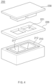
- FIG. 4 is a perspective view illustrating a battery case shaping apparatus according to another embodiment of the present invention.
- FIG. 5 is a side cross-sectional view illustrating a battery case shaping apparatus according to another embodiment of the present invention.
- Another embodiment of the present invention is different from the embodiment described above in that another embodiment provides an apparatus for shaping the battery case 100 according to the embodiment of the present invention. Therefore, the configuration of the battery case 100 may be understood as the same as the description in the above embodiment and the illustration in FIGS. 2 and 3 , and the effects thereof may also be expected in the same way.
- a battery case shaping apparatus 200 is an apparatus for shaping a battery case of a pouch-type secondary battery, which accommodates an electrode assembly therein, and may include a die plate 210, a stripper 220, and a punch 230.
- the die plate 210 has an upper surface, on which a pouch film is placed, and has a shaping portion 211, which is recessed downward from or passes through the upper surface, and a groove 212, which is formed around the shaping portion 211.
- a punch 230 described below is inserted into the shaping portion 211 to shape the cup portion 130 of the battery case 100, and a rib 222 described below is inserted into the groove 212 to shape the insulation failure-preventing portion 142 of the battery case 100.
- the stripper 220 presses and fixes the pouch film from above the die plate 210, and has a punch hole 221, which passes through an upper surface and a lower surface thereof at a position corresponding to the shaping portion 211, and a rib 222, which is formed around the punch hole 221 and faces the groove 212.
- a general stripper according to the related art is configured to serve only to fix a pouch film.
- the rib 222 is further formed along the circumference of the punch hole 221 of the stripper 220. Therefore, the stripper 220 may fix the pouch film and, at the same time, shape the insulation failure-preventing portion 142.
- the shape of the rib 222 may be formed to correspond to the shape of the groove 212 and the insulation failure-preventing portion 142 of the battery case 100.
- the punch 230 is inserted into the shaping portion 211 of the die plate 210 via the punch hole 221 of the stripper 220 to shape the cup portion 130 in the pouch film. That is, in a state in which the pouch film is fixed by the stripper 220, the punch 230 presses the pouch film. Accordingly, the pouch film is stretched, and the cup portion 130 is shaped into a shape corresponding to the punch 230 and the shaping portion 211.
- the groove 212 is formed in the die plate 210, and the rib 222 is further formed in the stripper 220. Accordingly, the insulation failure-preventing portion 142 may be formed together with the cup portion 130 of the battery case 100. A detailed configuration of the insulation failure-preventing portion 142 formed in the battery case 100 and effects thereof may be understood as the same as those described in the above embodiment.
- FIG. 6 is a flowchart illustrating a secondary battery manufacturing method according to another embodiment of the present invention.
- Another embodiment of the present invention is different from the embodiments described above in that another embodiment provides a method for shaping the battery case 100 according to the embodiment described above by using the battery case shaping apparatus 200 according to another embodiment described above. Therefore, the configurations of the battery case 100 and the battery case shaping apparatus 200 may be understood as the same as the above descriptions and the illustration in FIGS. 2 to 5 , and the effects thereof may also be expected in the same way.
- a secondary battery manufacturing method is a method for manufacturing a pouch-type secondary battery, which accommodates an electrode assembly therein, and the method includes shaping a battery case 100 that includes a cup portion 130 and an insulation failure-preventing portion 142 (S10) and accommodating an electrode assembly 10 in the cup portion 130 and sealing a sealing portion 141 of the battery case 100 (S20) .
- the insulation failure-preventing portion 142 is not formed during the operation (S20) of sealing the sealing portion 141, and the insulation failure-preventing portion 142 is formed during the operation (S10) of shaping the battery case 100 before the operation of sealing.
- the shaping of the battery case 100 includes placing a pouch film on a die plate 210 that has a shaping portion 211 and a groove 212 formed around the shaping portion 211 (S11), pressing and fixing the pouch film from above the die plate 210 by a stripper 220 that has a punch hole 221 and a rib 222 formed around the punch hole 221, wherein the rib 222 is inserted into the groove 212 to shape the insulation failure-preventing portion 142 in the pouch film (S12); and inserting the punch 230 into the shaping portion 211 of the die plate 210 via the punch hole 221 of the stripper 220 to form the cup portion 130 in the pouch film (S13) .
- the insulation failure-preventing portion 142 is formed before the operation (S20) of sealing the sealing portion 141. Therefore, even when a molten sealing material P of the battery case 100 flows out during the sealing operation (S20), the sealing material may be accommodated in the insulation failure-preventing portion 142 to thereby minimize insulation failure.
- the sealing portion 141 of a side portion 140 is heated, pressurized, and sealed using a bar-type or roller-type sealing tool. If necessary, in order to prevent mismatch between a first case 110 and a second case 120, pre-sealing is performed to seal a partial region of the sealing portion 141, and then, main-sealing may be performed to seal the entire sealing portion 141.
Landscapes
- Engineering & Computer Science (AREA)
- Chemical & Material Sciences (AREA)
- Chemical Kinetics & Catalysis (AREA)
- Electrochemistry (AREA)
- General Chemical & Material Sciences (AREA)
- Mechanical Engineering (AREA)
- Manufacturing & Machinery (AREA)
- Sealing Battery Cases Or Jackets (AREA)
- Secondary Cells (AREA)
Abstract
Description
- The present application claims the benefit of the priority of
Korean Patent Application No. 10-2022-0016539, filed on February 08, 2022 - The present invention relates to a battery case, a battery case shaping apparatus, and a secondary battery manufacturing method.
- Secondary batteries refer to chargeable and dischargeable batteries unlike primary batteries that are not chargeable, and there are several types of secondary batteries such as nickel cadmium batteries, nickel hydrogen batteries, lithium ion batteries, and lithium ion polymer batteries. The secondary batteries have been applied to and used for not only small products, such as digital cameras, laptop computers, mobile phones, PDAs, and E-bikes, but also large products requiring high power, such as electric vehicles and hybrid vehicles, and power storage devices or backup-power storage devices for storing surplus generated power and new renewable energy.
- The secondary batteries are classified into a pouch type, a can type, or the like according to a material of a battery case that accommodates an electrode assembly. In the pouch-type battery, the electrode assembly is accommodated in a pouch made of a flexible polymer material that has an irregular shape. Also, in the can-type battery, the electrode assembly is accommodated in a case made of a metal or plastic material or the like that has a predetermined shape.
-
FIG. 1 is a side cross-sectional view illustrating a battery case of a pouch-type secondary battery according to the related art. Abattery case 1 of the pouch-type secondary battery is manufactured by performing a press process on a flexible pouch film to shape a cup portion. The pouch film has a multi-layer structure in which a plurality of layers are laminated. In particular, the innermost layer includes a sealant layer and is formed on the innermost side of the pouch film to directly contact an electrode assembly, and this layer has the chemical resistance to an electrolyte and the thermal adhesion and also serves as a sealing material. The innermost layer is mainly made of a polyolefin-based resin and preferably made of polypropylene (PP). - When a cup portion of the battery case is shaped, an electrode assembly is accommodated in an accommodation space of the cup portion. Then, the secondary battery is manufactured by a heat sealing method in which the side of the battery case is pressed and heated with a sealing tool. During the sealing by the heat sealing method, it is preferable to perform the sealing for a long time at a low temperature range if possible. However, in order to increase a production rate, it is required to perform sealing for a short time at high temperature and high pressure.
- However, when the side is pressed at high temperature and pressure, a portion of the sealant layer, which is the innermost layer, is melted and pushed toward the accommodation space of the cup portion. The pushed sealant layer may be irregularly positioned in the accommodation space of the cup portion or may protrude toward the accommodation space to form a poly-ball. In this case, the pushed sealant layer may not only come into contact with the electrode assembly and contaminate the electrode assembly, but also reduce a sealing thickness of a sealing portion, causing direct insulation failure or insulation failure due to external physical impact.
- Therefore, it is required to develop a battery case and a method for manufacturing a secondary battery, which may secure the product quality while improving the productivity of a sealing process.
- The present invention has been made to solve the above limitation, and an objective of the present invention is to provide a battery case, a battery case shaping apparatus, and a secondary battery manufacturing method, which prevent insulation failure by allowing a sealing material melted in a sealing portion to be accommodated in an insulation failure-preventing portion, thereby improving both productivity and quality.
- A battery case according to an embodiment of the present invention is a battery case for a pouch-type secondary battery, which accommodates an electrode assembly therein, and includes a first case, a second case configured to cover the first case from above, a cup portion provided in at least one of the first case and the second case and having a space formed to accommodate the electrode assembly, and a side portion formed along an outer circumference of each of the first case and the second case, wherein the side portion includes a sealing portion sealed by bringing the first case and the second case into contact with each other and an insulation failure-preventing portion which is formed between the sealing portion and the cup portion and accommodates a sealing material melted in the sealing portion.
- The insulation failure-preventing portion may be recessed from the inside to the outside of the side portion with respect to a depth direction of the cup portion.
- The insulation failure-preventing portion may have a curved inner surface.
- The depth of the insulation failure-preventing portion may be less than the depth of the cup portion.
- The insulation failure-preventing portion may be formed at positions which correspond to each other in the side portion formed in the first case and the side portion formed in the second case.
- The insulation failure-preventing portion may be formed in an unsealed state so as not to be in contact with each other in the side portion formed in the first case and the side portion formed in the second case.
- The insulation failure-preventing portion may be continuously or intermittently formed along the circumference of the cup portion between the sealing portion and the cup portion.
- The side portion further may include a movement-preventing portion that connects the insulation failure-preventing portion and the cup portion to each other and prevents the sealing material accommodated in the insulation failure-preventing portion from moving to the cup portion.
- The movement-preventing portion may be formed in an unsealed state so as not to be in contact with each other in the side portion formed in the first case and the side portion formed in the second case.
- The thickness of the movement-preventing portion may be greater than the thickness of the sealing portion and less than the thickness of the insulation failure-preventing portion.
- The sealing material melted in the sealing portion may protrude toward the insulation failure-preventing portion.
- A battery case shaping apparatus according to another embodiment of the present invention is an apparatus for shaping a battery case of a pouch-type secondary battery, which accommodates an electrode assembly therein, and includes a die plate having an upper surface, on which a pouch film is placed, the die plate having a shaping portion, which is recessed downward from or passes through the upper surface, and a groove, which is formed around the shaping portion, a stripper configured to press and fix the pouch film from above the die plate, the stripper having a punch hole, which passes through an upper surface and a lower surface thereof at a position corresponding to the shaping portion, and a rib, which is formed around the punch hole and faces the groove, and a punch inserted into the shaping portion of the die plate via the punch hole of the stripper to shape a cup portion in the pouch film.
- A secondary battery manufacturing method according to another embodiment of the present invention is a method for manufacturing a pouch-type secondary battery, which accommodates an electrode assembly therein, and includes shaping a battery case that includes a cup portion and an insulation failure-preventing portion and accommodating the electrode assembly in the cup portion and sealing a sealing portion of the battery case, wherein the shaping of the battery case includes placing a pouch film on a die plate that has a shaping portion and a groove formed around the shaping portion, pressing and fixing the pouch film from above the die plate by a stripper that has a punch hole and a rib formed around the punch hole, wherein the rib is inserted into the groove to shape the insulation failure-preventing portion in the pouch film, and inserting a punch into the shaping portion of the die plate via the punch hole of the stripper to shape the cup portion in the pouch film.
- In a battery case according to the present invention, a sealing material melted in a sealing portion is accommodated in an insulation failure-preventing portion, and thus, insulation failure is minimized by preventing a discharged sealing material from being irregularly located or protruding in a cup portion. A space formed in the insulation failure-preventing portion may act as a buffer against external physical impact, thereby preventing additional insulation failure and improving the safety of a secondary battery.
- In addition, even when sealing is performed at high temperature and pressure, the sealing material is accommodated in the insulation failure-preventing portion. Accordingly, the speed of the sealing process may be increased, thereby securing both productivity and quality of the battery case.
-
-
FIG. 1 is a side cross-sectional view illustrating a battery case of a pouch-type secondary battery according to the related art. -
FIG. 2 is a perspective view illustrating a battery case and an electrode assembly accommodated in the battery case according to an embodiment of the present invention. -
FIG. 3 is a side cross-sectional view illustrating a battery case according to an embodiment of the present invention. -
FIG. 4 is a perspective view illustrating a battery case shaping apparatus according to another embodiment of the present invention. -
FIG. 5 is a side cross-sectional view illustrating a battery case shaping apparatus according to another embodiment of the present invention. -
FIG. 6 is a flowchart illustrating a secondary battery manufacturing method according to another embodiment of the present invention. - Hereinafter, embodiments of the present invention are described in detail with reference to the accompanying drawings so as to be easily carried out by a person skilled in the art to which the present invention pertains. However, the present invention may be embodied in various different forms, and is neither limited nor restricted to the following embodiments.
- In order to clearly describe the present invention, detailed descriptions of parts irrelevant to the invention or detailed descriptions of related well-known technologies that may unnecessarily obscure subject matters of the invention are omitted. In the specification, when reference numerals are given to components in each of the drawings, the same or similar components are designated by the same or similar reference numerals throughout the specification.
- Also, terms or words used in the description and claims should not be restrictively interpreted as ordinary meanings or dictionary-based meanings, but should be interpreted as meanings and concepts conforming to the technical ideas of the present invention on the basis of the principle that an inventor can properly define the concept of a term so as to describe his or her invention in the best ways.
-
FIG. 2 is a perspective view illustrating a battery case and an electrode assembly accommodated in the battery case according to an embodiment of the present invention.FIG. 3 is a side cross-sectional view illustrating a battery case according to an embodiment of the present invention. - Referring to
FIGS. 2 and3 , abattery case 100 according to an embodiment of the present invention is provided, and thebattery case 100 for a pouch-type secondary battery, which accommodates anelectrode assembly 10 therein, includes afirst case 110, asecond case 120, acup portion 130, and aside portion 140. - First, the
first case 110 and thesecond case 120 are formed by shaping a pouch film, and thesecond case 120 covers thefirst case 110 from above in a state in which thefirst case 110 is positioned at the bottom. Here, thesecond case 120 may cover thefirst case 110 in a state in which thefirst case 110 and thesecond case 120 are separated from each other, but the embodiment is not limited thereto. Thefirst case 110 and thesecond case 120 may be shaped from a single pouch film, and thesecond case 120 may be folded above thefirst case 110 by a folding device and cover the upper portion thereof. - The pouch film has a multi-layer structure in which a plurality of layers are laminated, and this multi-layer structure may be configured by laminating a metal layer on an inner layer and laminating an outer layer on the metal layer. The inner layer includes a layer positioned on the innermost side of the pouch film, serves as a sealing material having the chemical resistance to an electrolyte and the thermal adhesion, and is made of mainly a polyolefin-based resin and preferably made of polypropylene (PP). The metal layer includes a layer disposed between the inner layer and the outer layer, maintains mechanical strength of the pouch film, and serves as a moisture and oxygen barrier. The metal layer may be made of an alloy of iron (Fe), carbon (C), chromium (Cr), and manganese (Mn), an alloy of iron (Fe), carbon (C), chromium (Cr), and nickel (Ni), or the like, and preferably made of aluminum (Al). The outer layer includes a layer formed on the outermost side of the pouch film, serves to protect the battery from external impact, and is required to have insulation and thermal resistance because this layer comes into direct contact with hardware. The material of the outer layer may include a single layer of one or a composite layer of two or more selected from polyethylene (PE), polypropylene (PP), polyethylene terephthalate (PET), nylon, low density polyethylene (LDPE), and high density polyethylene (HDPE).
- The
cup portion 130 is provided in at least one of thefirst case 110 or thesecond case 120 and has a space formed to accommodate theelectrode assembly 10. Thecup portion 130 may be formed only in thefirst case 110, may be formed only in thesecond case 120, or may be formed in both thefirst case 110 and thesecond case 120. - The
side portion 140 represents regions which are formed along outer circumferences of thefirst case 110 and thesecond case 120. For example, for abattery case 100 in which afirst case 110 and asecond case 120 are shaped from a single pouch film and thesecond case 120 is folded above thefirst case 110 to cover the upper portion thereof, theside portion 140 may represent edges formed along the outer circumferences of thefirst case 110 and thesecond case 120, except for regions folded between thefirst case 110 and thesecond case 120. However, when thesecond case 120 covers thefirst case 110 in a state in which thefirst case 110 or thesecond case 120 is separated, theside portion 140 may represent edges of each of thefirst case 110 and thesecond case 120 separated from each other. - Meanwhile, the
side portion 140 of thebattery case 100 according to an embodiment of the present invention includes a sealingportion 141, which is sealed by bringing thefirst case 110 and thesecond case 120 into contact with each other, and an insulation failure-preventingportion 142, which is formed between the sealingportion 141 and thecup portion 130 and accommodates a sealing material melted in the sealingportion 141. Therefore, in thebattery case 100 according to an embodiment of the present invention, the sealing material melted in the sealingportion 141 may protrude toward the insulation failure-preventingportion 142. - In the
battery case 100 according to the present invention as described above, a sealing material P is accommodated in the insulation failure-preventingportion 142 even when melted due to heating and pressing in the sealingportion 141 and flowing out. Accordingly, it is possible to prevent insulation failure that occurs as the sealing material P is locally located at irregular positions. In addition, even when melted, the sealing material P is not directly exposed to thecup portion 130 but is accommodated in the insulation failure-preventingportion 142. Therefore, sealing may be performed at higher temperature and pressure to increase a process speed, thereby securing both productivity and quality of thebattery case 100. - Hereinafter, the insulation failure-preventing
portion 142 is described in detail with reference back toFIGS. 2 and3 . - The insulation failure-preventing
portion 142 may be recessed from the inside to the outside of theside portion 140 with respect to a depth direction of thecup portion 130. Here, when thesecond case 120 covers thefirst case 110 from above, the inside of theside portion 140 may represent one side where thefirst case 110 and thesecond case 120 face each other, and the outside thereof may represent an opposite side from the inside of thefirst case 110 and thesecond case 120. In addition, when an inner region and an outer region of thebattery case 100 are distinguished by covering thesecond case 120 from above with thefirst case 110, the side located in the inner region of thebattery case 100 may be referred to as the inside. - As described above, the insulation failure-preventing
portion 142 of thebattery case 100 according to the present invention is recessed from the inside to the outside of theside portion 140, and thus, a space is provided in theside portion 140. This space may accommodate the sealing material P that melts and flows out of the sealingportion 141, and may act as a buffer against external physical impact, thereby preventing the occurrence of additional insulation failure and improving the safety of the secondary battery after sealing. - Also, the insulation failure-preventing
portion 142 may have a curved inner surface. Here, the inner surface may represent a surface of the insulation failure-preventingportion 142 which is formed inside theside portion 140. The insulation failure-preventingportion 142 includes a recessed space as described above, and the molten sealing material P may flow out and be accommodated in the insulation failure-preventingportion 142. Also, when the sealing material P does not flow out, this space may remain empty. Here, when an external impact is applied, there is a risk that thebattery case 100 may be broken. However, in the present invention, the insulation failure-preventingportion 142 has the curved inner surface, and thus, even when the molten sealing material P is not accommodated, it is possible to minimize the risk of breakage of thebattery case 100 that may occur due to the external impact. - Next, a depth D1 of the insulation failure-preventing
portion 142 may be less than a depth D2 of thecup portion 130. When thesecond case 120 covers thefirst case 110 from above, the insulation failure-preventingportion 142 has a shape protruding to the outside of thebattery case 100. Here, when the depth D1 of the insulation failure-preventingportion 142 is greater than the depth D2 of thecup portion 130, it is not so easy to accommodate a secondary battery cell, and the risk of damage to the insulation failure-preventingportion 142 is significantly increased. In addition, the insulation failure-preventingportion 142 has a relatively small width. Therefore, when the depth thereof is greater than the depth of thecup portion 130, the shaping is remarkably deteriorated, and it is difficult to maintain the shape even when shaped. - Therefore, the depth D1 of the insulation failure-preventing
portion 142 is smaller than the depth D2 of thecup portion 130, and thus, the sealing material P melted from the sealingportion 141 may be appropriately accommodated while securing the shaping and structural stability of the insulation failure-preventingportion 142. - Also, the insulation failure-preventing
portion 142 may be formed at positions which correspond to each other in theside portion 140 formed in thefirst case 110 and theside portion 140 formed in thesecond case 120. Therefore, an area occupied by the insulation failure-preventingportion 142 is minimized, and the sealingportion 141 having a larger area is obtained. Accordingly, it is possible to strengthen the sealing force and facilitate sealing, and at the same time, it is possible to maximize the space in which the molten sealing material P may be accommodated. - The insulation failure-preventing
portion 142 may be formed in an unsealed state so as not to be in contact with each other in theside portion 140 formed in thefirst case 110 and theside portion 140 formed in thesecond case 120. According to the related art, a stepped portion or groove is provided in a battery case sealing apparatus instead of a battery case shaping apparatus. During a process of sealing a pouch-type battery case, a protrusion or raised portion is formed on the sealing portion of the battery case. However, in a sealing apparatus or sealing method according to the related art, a battery case is presented in a sealed state even at the protrusion or raised portion. Therefore, a sealing material melted in a sealing portion adjacent to a cup portion still flows into the cup portion, resulting in insulation failure. In addition, when a physical impact is applied from the outside of the battery case, it is difficult to expect a buffering effect. - However, in the
battery case 100 according to the present invention, the insulation failure-preventingportion 142 is provided while forming a space in an unsealed state. Therefore, the molten sealing material P flowing out of the sealingportion 141 is sufficiently accommodated in the space, the sealing material P is prevented from being exposed to thecup portion 130, and the region, in which the sealing material P is not accommodated, remains as an empty space and may serve as a buffer space for absorbing external impact. - Meanwhile, the insulation failure-preventing
portion 142 may be continuously or intermittently formed along the circumference of thecup portion 130 between the sealingportion 141 and thecup portion 130. - The continuous formation of the insulation failure-preventing
portion 142 may represent that a linearly connected single portion is formed along the circumference of thecup portion 130 in each of thefirst case 110 or thesecond case 120. In this case, it is possible to minimize the exposure of the sealing material P melted in the sealingportion 141 to thecup portion 130 and to maximize the insulation failure prevention and the buffering effect. - Meanwhile, the intermittent formation of the insulation failure-preventing
portion 142 may represent that a plurality of insulation failure-preventingportions 142 are formed at certain intervals along the circumference of thecup portion 130 in each of thefirst case 110 or thesecond case 120. In this case, additional sealing is performed in each of regions between the plurality of insulation failure-preventingportions 142, and thus, it is possible to simultaneously promote the insulation failure prevention and the sealing force enhancement. - The
side portion 140 of thebattery case 100 according to an embodiment of the present invention may further include a movement-preventingportion 143 that connects the insulation failure-preventingportion 142 and thecup portion 130 to each other and prevents the sealing material P accommodated in the insulation failure-preventingportion 142 from moving to thecup portion 130. That is, the movement-preventingportion 143 is formed between the recessed insulation failure-preventingportion 142 and the recessedcup portion 130, and protrudes from the outside to the inside relatively compared to the insulation failure-preventingportion 142 and thecup portion 130, thus making it possible to prevent the sealing material P accommodated in the insulation failure-preventingportion 142 from moving to thecup portion 130. - Also, a thickness T1 of the movement-preventing
portion 143 may be greater than a thickness T2 of the sealingportion 141 and less than a thickness T3 of the insulation failure-preventingportion 142. In particular, the thickness T1 of the movement-preventingportion 143 is less than the thickness T3 of the insulation failure-preventingportion 142, and thus, it is possible to prevent the sealing material P accommodated in the insulation failure-preventingportion 142 from moving to thecup portion 130. - Meanwhile, the movement-preventing
portion 143 may be formed in an unsealed state so as not to be in contact with each other in theside portion 140 formed in thefirst case 110 and theside portion 140 formed in thesecond case 120. Accordingly, the movement-preventingportion 143 together with the insulation failure-preventingportion 142 described above may be provided while forming a space in an unsealed state, and thus, it is possible to prevent the sealing material P accommodated in the insulation failure-preventingportion 142 from moving to thecup portion 130. Also, the movement-preventingportion 143 may also accommodate some of the melted sealing material P, which flows out of the sealingportion 141, remain as an empty space when not filled with the sealing material P, and also serve as a buffer space for absorbing external impact. -
FIG. 4 is a perspective view illustrating a battery case shaping apparatus according to another embodiment of the present invention.FIG. 5 is a side cross-sectional view illustrating a battery case shaping apparatus according to another embodiment of the present invention. - Another embodiment of the present invention is different from the embodiment described above in that another embodiment provides an apparatus for shaping the
battery case 100 according to the embodiment of the present invention. Therefore, the configuration of thebattery case 100 may be understood as the same as the description in the above embodiment and the illustration inFIGS. 2 and3 , and the effects thereof may also be expected in the same way. - Referring to
FIGS. 4 and5 , a batterycase shaping apparatus 200 according to another embodiment of the present invention is an apparatus for shaping a battery case of a pouch-type secondary battery, which accommodates an electrode assembly therein, and may include adie plate 210, astripper 220, and apunch 230. - Hereinafter, the apparatus is described with reference to
FIGS. 2 to 5 . First, thedie plate 210 has an upper surface, on which a pouch film is placed, and has a shapingportion 211, which is recessed downward from or passes through the upper surface, and agroove 212, which is formed around the shapingportion 211. Apunch 230 described below is inserted into the shapingportion 211 to shape thecup portion 130 of thebattery case 100, and arib 222 described below is inserted into thegroove 212 to shape the insulation failure-preventingportion 142 of thebattery case 100. - The
stripper 220 presses and fixes the pouch film from above thedie plate 210, and has apunch hole 221, which passes through an upper surface and a lower surface thereof at a position corresponding to the shapingportion 211, and arib 222, which is formed around thepunch hole 221 and faces thegroove 212. A general stripper according to the related art is configured to serve only to fix a pouch film. However, in the batterycase shaping apparatus 200 according to the present invention, therib 222 is further formed along the circumference of thepunch hole 221 of thestripper 220. Therefore, thestripper 220 may fix the pouch film and, at the same time, shape the insulation failure-preventingportion 142. Here, the shape of therib 222 may be formed to correspond to the shape of thegroove 212 and the insulation failure-preventingportion 142 of thebattery case 100. - The
punch 230 is inserted into the shapingportion 211 of thedie plate 210 via thepunch hole 221 of thestripper 220 to shape thecup portion 130 in the pouch film. That is, in a state in which the pouch film is fixed by thestripper 220, thepunch 230 presses the pouch film. Accordingly, the pouch film is stretched, and thecup portion 130 is shaped into a shape corresponding to thepunch 230 and the shapingportion 211. - In the battery
case shaping apparatus 200 according to another embodiment of the present invention described above, thegroove 212 is formed in thedie plate 210, and therib 222 is further formed in thestripper 220. Accordingly, the insulation failure-preventingportion 142 may be formed together with thecup portion 130 of thebattery case 100. A detailed configuration of the insulation failure-preventingportion 142 formed in thebattery case 100 and effects thereof may be understood as the same as those described in the above embodiment. -
FIG. 6 is a flowchart illustrating a secondary battery manufacturing method according to another embodiment of the present invention. - Another embodiment of the present invention is different from the embodiments described above in that another embodiment provides a method for shaping the
battery case 100 according to the embodiment described above by using the batterycase shaping apparatus 200 according to another embodiment described above. Therefore, the configurations of thebattery case 100 and the batterycase shaping apparatus 200 may be understood as the same as the above descriptions and the illustration inFIGS. 2 to 5 , and the effects thereof may also be expected in the same way. - Referring to
FIG. 6 together withFIGS. 2 to 5 , a secondary battery manufacturing method according to another embodiment of the present invention is a method for manufacturing a pouch-type secondary battery, which accommodates an electrode assembly therein, and the method includes shaping abattery case 100 that includes acup portion 130 and an insulation failure-preventing portion 142 (S10) and accommodating anelectrode assembly 10 in thecup portion 130 and sealing a sealingportion 141 of the battery case 100 (S20) . In the secondary battery manufacturing method according to the present invention described above, the insulation failure-preventingportion 142 is not formed during the operation (S20) of sealing the sealingportion 141, and the insulation failure-preventingportion 142 is formed during the operation (S10) of shaping thebattery case 100 before the operation of sealing. - When described in detail, the shaping of the battery case 100 (S10) includes placing a pouch film on a
die plate 210 that has a shapingportion 211 and agroove 212 formed around the shaping portion 211 (S11), pressing and fixing the pouch film from above thedie plate 210 by astripper 220 that has apunch hole 221 and arib 222 formed around thepunch hole 221, wherein therib 222 is inserted into thegroove 212 to shape the insulation failure-preventingportion 142 in the pouch film (S12); and inserting thepunch 230 into the shapingportion 211 of thedie plate 210 via thepunch hole 221 of thestripper 220 to form thecup portion 130 in the pouch film (S13) . - As describe above, in the secondary battery manufacturing method according to the present invention, the insulation failure-preventing
portion 142 is formed before the operation (S20) of sealing the sealingportion 141. Therefore, even when a molten sealing material P of thebattery case 100 flows out during the sealing operation (S20), the sealing material may be accommodated in the insulation failure-preventingportion 142 to thereby minimize insulation failure. - Meanwhile, during the operation (S20) of sealing the sealing
portion 141, the sealingportion 141 of aside portion 140 is heated, pressurized, and sealed using a bar-type or roller-type sealing tool. If necessary, in order to prevent mismatch between afirst case 110 and asecond case 120, pre-sealing is performed to seal a partial region of the sealingportion 141, and then, main-sealing may be performed to seal theentire sealing portion 141. - Although the present invention is described by specific embodiments and drawings, the present invention is not limited thereto, and various changes and modifications may be made by a person skilled in the art to which the present invention pertains within the technical idea of the present invention and equivalent scope of the appended claims.
-
- 10: Electrode assembly
- 100: Battery case
- 110: First case
- 120: Second case
- 130: Cup portion
- 140: Side portion
- 141: Sealing portion
- 142: Insulation failure-preventing portion
- 143: Movement-preventing portion
- P: Sealing material
- D1: Depth of insulation failure-preventing portion
- D2: Depth of cup portion
- T1: Thickness of movement-preventing portion
- T2: Thickness of sealing portion
- T3: Thickness of insulation failure-preventing portion
- 200: Battery case shaping apparatus
- 210: Die plate
- 211: Shaping portion
- 212: Groove
- 220: Stripper
- 221: Punch hole
- 222: Rib
- 230: Punch
Claims (13)
- A battery case for a pouch-type secondary battery, which accommodates an electrode assembly therein, the battery case comprising:a first case;a second case configured to cover the first case from above;a cup portion provided in at least one of the first case and the second case and having a space formed to accommodate the electrode assembly; anda side portion formed along an outer circumference of each of the first case and the second case,wherein the side portion comprises:a sealing portion sealed by bringing the first case and the second case into contact with each other; andan insulation failure-preventing portion which is formed between the sealing portion and the cup portion and accommodates a sealing material melted in the sealing portion.
- The battery case of claim 1, wherein the insulation failure-preventing portion is recessed from the inside to the outside of the side portion with respect to a depth direction of the cup portion.
- The battery case of claim 1, wherein the insulation failure-preventing portion has a curved inner surface.
- The battery case of claim 1, wherein the depth of the insulation failure-preventing portion is less than the depth of the cup portion.
- The battery case of claim 1, wherein the insulation failure-preventing portion is formed at positions which correspond to each other in the side portion formed in the first case and the side portion formed in the second case.
- The battery case of claim 5, wherein the insulation failure-preventing portion is formed in an unsealed state so as not to be in contact with each other in the side portion formed in the first case and the side portion formed in the second case.
- The battery case of claim 1, wherein the insulation failure-preventing portion is continuously or intermittently formed along the circumference of the cup portion between the sealing portion and the cup portion.
- The battery case of claim 1, wherein the side portion further comprises a movement-preventing portion that connects the insulation failure-preventing portion and the cup portion to each other and prevents the sealing material accommodated in the insulation failure-preventing portion from moving to the cup portion.
- The battery case of claim 8, wherein the movement-preventing portion is formed in an unsealed state so as not to be in contact with each other in the side portion formed in the first case and the side portion formed in the second case.
- The battery case of claim 9, wherein the thickness of the movement-preventing portion is greater than the thickness of the sealing portion and less than the thickness of the insulation failure-preventing portion.
- The battery case of claim 1, wherein the sealing material melted in the sealing portion protrudes toward the insulation failure-preventing portion.
- An apparatus for shaping a battery case of a pouch-type secondary battery, which accommodates an electrode assembly therein, the apparatus comprising:a die plate having an upper surface, on which a pouch film is placed, the die plate having a shaping portion, which is recessed downward from or passes through the upper surface, and a groove, which is formed around the shaping portion;a stripper configured to press and fix the pouch film from above the die plate, the stripper having a punch hole, which passes through an upper surface and a lower surface thereof at a position corresponding to the shaping portion, and a rib, which is formed around the punch hole and faces the groove; anda punch inserted into the shaping portion of the die plate via the punch hole of the stripper to shape a cup portion in the pouch film.
- A method for manufacturing a pouch-type secondary battery, which accommodates an electrode assembly therein, the method comprising:shaping a battery case that comprises a cup portion and an insulation failure-preventing portion; andaccommodating the electrode assembly in the cup portion and sealing a sealing portion of the battery case,wherein the shaping of the battery case comprises:placing a pouch film on a die plate that has a shaping portion and a groove formed around the shaping portion;pressing and fixing the pouch film from above the die plate by a stripper that has a punch hole and a rib formed around the punch hole, wherein the rib is inserted into the groove to shape the insulation failure-preventing portion in the pouch film; andinserting a punch into the shaping portion of the die plate via the punch hole of the stripper to shape the cup portion in the pouch film.
Applications Claiming Priority (2)
| Application Number | Priority Date | Filing Date | Title |
|---|---|---|---|
| KR1020220016539A KR102921535B1 (en) | 2022-02-08 | 2022-02-08 | Battery case, battery case forming apparatus and secondary battery manufacturing method |
| PCT/KR2023/001296 WO2023153688A1 (en) | 2022-02-08 | 2023-01-27 | Battery case, battery case molding device, and secondary battery manufacturing method |
Publications (2)
| Publication Number | Publication Date |
|---|---|
| EP4478492A1 true EP4478492A1 (en) | 2024-12-18 |
| EP4478492A4 EP4478492A4 (en) | 2025-08-20 |
Family
ID=87564618
Family Applications (1)
| Application Number | Title | Priority Date | Filing Date |
|---|---|---|---|
| EP23753039.9A Pending EP4478492A4 (en) | 2022-02-08 | 2023-01-27 | Battery case, battery case molding device, and secondary battery manufacturing method |
Country Status (6)
| Country | Link |
|---|---|
| US (1) | US20250149694A1 (en) |
| EP (1) | EP4478492A4 (en) |
| JP (1) | JP7831739B2 (en) |
| KR (1) | KR102921535B1 (en) |
| CN (1) | CN118648161A (en) |
| WO (1) | WO2023153688A1 (en) |
Families Citing this family (1)
| Publication number | Priority date | Publication date | Assignee | Title |
|---|---|---|---|---|
| WO2025206849A1 (en) * | 2024-03-29 | 2025-10-02 | 주식회사 엘지에너지솔루션 | Battery case molding apparatus and battery case |
Family Cites Families (9)
| Publication number | Priority date | Publication date | Assignee | Title |
|---|---|---|---|---|
| WO2012030080A2 (en) | 2010-08-30 | 2012-03-08 | 주식회사 엘지화학 | Rechargeable battery having a novel structure |
| KR101940150B1 (en) | 2015-12-11 | 2019-01-18 | 주식회사 엘지화학 | Sealing apparatus for secondary battery |
| KR102103899B1 (en) * | 2017-05-24 | 2020-04-24 | 주식회사 엘지화학 | Secondary battery and manufactury methode for the same |
| KR20190038094A (en) * | 2017-09-29 | 2019-04-08 | 에스케이이노베이션 주식회사 | Apparatus for forming a pouch for secondary battery |
| KR102143625B1 (en) * | 2017-11-14 | 2020-08-11 | 삼성에스디아이 주식회사 | Pouch type secondary battery having non-sealing portion |
| KR102501251B1 (en) * | 2018-03-16 | 2023-02-20 | 주식회사 엘지에너지솔루션 | The Apparatus For Taping The Secondary Battery |
| KR102334022B1 (en) * | 2018-11-02 | 2021-12-02 | 주식회사 엘지에너지솔루션 | Pouch-type Secondary Battery Having Groove for Replenishing an electrolyte |
| CN113597702B (en) * | 2020-03-24 | 2023-01-24 | 东莞新能安科技有限公司 | Electrochemical device and electronic device |
| KR102414216B1 (en) | 2020-08-03 | 2022-06-28 | 타이아(주) | Direct data provision system to cloud server based on connection of control device to wired/wireless communication network |
-
2022
- 2022-02-08 KR KR1020220016539A patent/KR102921535B1/en active Active
-
2023
- 2023-01-27 JP JP2024546288A patent/JP7831739B2/en active Active
- 2023-01-27 CN CN202380016822.6A patent/CN118648161A/en active Pending
- 2023-01-27 WO PCT/KR2023/001296 patent/WO2023153688A1/en not_active Ceased
- 2023-01-27 EP EP23753039.9A patent/EP4478492A4/en active Pending
- 2023-01-27 US US18/730,152 patent/US20250149694A1/en active Pending
Also Published As
| Publication number | Publication date |
|---|---|
| WO2023153688A1 (en) | 2023-08-17 |
| JP7831739B2 (en) | 2026-03-17 |
| US20250149694A1 (en) | 2025-05-08 |
| EP4478492A4 (en) | 2025-08-20 |
| CN118648161A (en) | 2024-09-13 |
| KR102921535B1 (en) | 2026-02-03 |
| JP2025504156A (en) | 2025-02-06 |
| KR20230120033A (en) | 2023-08-16 |
Similar Documents
| Publication | Publication Date | Title |
|---|---|---|
| EP3249732B1 (en) | Sealing apparatus of pouch-type rechargeable battery | |
| KR102176631B1 (en) | The Method And The Apparatus For Forming Pouch | |
| KR102256599B1 (en) | Pressing jig and method of fabricating secondary battery using the same | |
| CN100361326C (en) | Film-covered electrical device and manufacturing method thereof | |
| KR102667401B1 (en) | The Apparatus And The Method For Forming Pouch | |
| KR102334022B1 (en) | Pouch-type Secondary Battery Having Groove for Replenishing an electrolyte | |
| JP7508137B2 (en) | Secondary battery and seal block | |
| KR20160080559A (en) | A pouch type secondary battery with an enhanced sealing part and a method for manufacturing the secondary battery | |
| KR20180038765A (en) | Method of Manufacturing Battery Case Using Film Member for Forming | |
| US20250149694A1 (en) | Battery Case, Battery Case Shaping Apparatus, and Secondary Battery Manufacturing Method | |
| KR100624967B1 (en) | Pouch-type lithium secondary battery and manufacturing method thereof | |
| KR102501251B1 (en) | The Apparatus For Taping The Secondary Battery | |
| JP7658666B2 (en) | Battery case molding device, molding method, and battery case | |
| KR102168946B1 (en) | Method for Manufacturing Battery Cell Using Blow Forming | |
| US20250364641A1 (en) | Power storage device, power storage device case, and power storage device exterior material | |
| KR102964379B1 (en) | The Apparatus And The Method For Forming Pouch | |
| KR102892269B1 (en) | Pouch sealing apparatus and sealing method | |
| EP4207440B1 (en) | Secondary battery and a method of manufacturing a secondary battery | |
| US20250364640A1 (en) | Power storage device, power storage device case, and power storage device exterior material | |
| EP4207441B1 (en) | Pouch-type secondary battery comprising a pouch bag | |
| KR102836760B1 (en) | Secondary battery and sealing device for manufacturing the same | |
| EP4411943B1 (en) | Pouch-type battery case and secondary battery including the same | |
| US20250140997A1 (en) | Secondary Battery and Sealing Device for Manufacturing the Same | |
| EP4712221A1 (en) | Battery and method for manufacturing the battery | |
| EP4571953A1 (en) | Pouch-type battery case and forming device therefor |
Legal Events
| Date | Code | Title | Description |
|---|---|---|---|
| STAA | Information on the status of an ep patent application or granted ep patent |
Free format text: STATUS: THE INTERNATIONAL PUBLICATION HAS BEEN MADE |
|
| PUAI | Public reference made under article 153(3) epc to a published international application that has entered the european phase |
Free format text: ORIGINAL CODE: 0009012 |
|
| STAA | Information on the status of an ep patent application or granted ep patent |
Free format text: STATUS: REQUEST FOR EXAMINATION WAS MADE |
|
| 17P | Request for examination filed |
Effective date: 20240703 |
|
| AK | Designated contracting states |
Kind code of ref document: A1 Designated state(s): AL AT BE BG CH CY CZ DE DK EE ES FI FR GB GR HR HU IE IS IT LI LT LU LV MC ME MK MT NL NO PL PT RO RS SE SI SK SM TR |
|
| DAV | Request for validation of the european patent (deleted) | ||
| DAX | Request for extension of the european patent (deleted) | ||
| RIC1 | Information provided on ipc code assigned before grant |
Ipc: B29C 65/00 20060101ALI20250411BHEP Ipc: B29C 43/36 20060101ALI20250411BHEP Ipc: H01M 10/052 20100101ALI20250411BHEP Ipc: H01M 10/04 20060101ALI20250411BHEP Ipc: H01M 50/184 20210101ALI20250411BHEP Ipc: H01M 50/124 20210101ALI20250411BHEP Ipc: H01M 50/105 20210101AFI20250411BHEP |
|
| A4 | Supplementary search report drawn up and despatched |
Effective date: 20250717 |
|
| RIC1 | Information provided on ipc code assigned before grant |
Ipc: H01M 50/105 20210101AFI20250711BHEP Ipc: H01M 50/124 20210101ALI20250711BHEP Ipc: H01M 50/184 20210101ALI20250711BHEP Ipc: H01M 10/04 20060101ALI20250711BHEP Ipc: H01M 10/052 20100101ALI20250711BHEP Ipc: B29C 43/36 20060101ALI20250711BHEP Ipc: B29C 65/00 20060101ALI20250711BHEP |
|
| STAA | Information on the status of an ep patent application or granted ep patent |
Free format text: STATUS: EXAMINATION IS IN PROGRESS |
|
| 17Q | First examination report despatched |
Effective date: 20260218 |