EP4478471A1 - Secondary battery and method for producing secondary battery - Google Patents
Secondary battery and method for producing secondary battery Download PDFInfo
- Publication number
- EP4478471A1 EP4478471A1 EP23752911.0A EP23752911A EP4478471A1 EP 4478471 A1 EP4478471 A1 EP 4478471A1 EP 23752911 A EP23752911 A EP 23752911A EP 4478471 A1 EP4478471 A1 EP 4478471A1
- Authority
- EP
- European Patent Office
- Prior art keywords
- separator
- secondary battery
- plate
- spacer
- negative plate
- Prior art date
- Legal status (The legal status is an assumption and is not a legal conclusion. Google has not performed a legal analysis and makes no representation as to the accuracy of the status listed.)
- Pending
Links
Images




Classifications
-
- H—ELECTRICITY
- H01—ELECTRIC ELEMENTS
- H01M—PROCESSES OR MEANS, e.g. BATTERIES, FOR THE DIRECT CONVERSION OF CHEMICAL ENERGY INTO ELECTRICAL ENERGY
- H01M10/00—Secondary cells; Manufacture thereof
- H01M10/05—Accumulators with non-aqueous electrolyte
- H01M10/052—Li-accumulators
-
- H—ELECTRICITY
- H01—ELECTRIC ELEMENTS
- H01M—PROCESSES OR MEANS, e.g. BATTERIES, FOR THE DIRECT CONVERSION OF CHEMICAL ENERGY INTO ELECTRICAL ENERGY
- H01M10/00—Secondary cells; Manufacture thereof
- H01M10/05—Accumulators with non-aqueous electrolyte
- H01M10/058—Construction or manufacture
- H01M10/0587—Construction or manufacture of accumulators having only wound construction elements, i.e. wound positive electrodes, wound negative electrodes and wound separators
-
- H—ELECTRICITY
- H01—ELECTRIC ELEMENTS
- H01M—PROCESSES OR MEANS, e.g. BATTERIES, FOR THE DIRECT CONVERSION OF CHEMICAL ENERGY INTO ELECTRICAL ENERGY
- H01M10/00—Secondary cells; Manufacture thereof
- H01M10/42—Methods or arrangements for servicing or maintenance of secondary cells or secondary half-cells
- H01M10/4235—Safety or regulating additives or arrangements in electrodes, separators or electrolyte
-
- H—ELECTRICITY
- H01—ELECTRIC ELEMENTS
- H01M—PROCESSES OR MEANS, e.g. BATTERIES, FOR THE DIRECT CONVERSION OF CHEMICAL ENERGY INTO ELECTRICAL ENERGY
- H01M4/00—Electrodes
- H01M4/02—Electrodes composed of, or comprising, active material
- H01M4/04—Processes of manufacture in general
- H01M4/0438—Processes of manufacture in general by electrochemical processing
- H01M4/044—Activating, forming or electrochemical attack of the supporting material
- H01M4/0445—Forming after manufacture of the electrode, e.g. first charge, cycling
-
- H—ELECTRICITY
- H01—ELECTRIC ELEMENTS
- H01M—PROCESSES OR MEANS, e.g. BATTERIES, FOR THE DIRECT CONVERSION OF CHEMICAL ENERGY INTO ELECTRICAL ENERGY
- H01M4/00—Electrodes
- H01M4/02—Electrodes composed of, or comprising, active material
- H01M4/36—Selection of substances as active materials, active masses, active liquids
- H01M4/38—Selection of substances as active materials, active masses, active liquids of elements or alloys
- H01M4/381—Alkaline or alkaline earth metals elements
- H01M4/382—Lithium
-
- H—ELECTRICITY
- H01—ELECTRIC ELEMENTS
- H01M—PROCESSES OR MEANS, e.g. BATTERIES, FOR THE DIRECT CONVERSION OF CHEMICAL ENERGY INTO ELECTRICAL ENERGY
- H01M50/00—Constructional details or processes of manufacture of the non-active parts of electrochemical cells other than fuel cells, e.g. hybrid cells
- H01M50/40—Separators; Membranes; Diaphragms; Spacing elements inside cells
- H01M50/403—Manufacturing processes of separators, membranes or diaphragms
-
- H—ELECTRICITY
- H01—ELECTRIC ELEMENTS
- H01M—PROCESSES OR MEANS, e.g. BATTERIES, FOR THE DIRECT CONVERSION OF CHEMICAL ENERGY INTO ELECTRICAL ENERGY
- H01M50/00—Constructional details or processes of manufacture of the non-active parts of electrochemical cells other than fuel cells, e.g. hybrid cells
- H01M50/40—Separators; Membranes; Diaphragms; Spacing elements inside cells
- H01M50/409—Separators, membranes or diaphragms characterised by the material
- H01M50/449—Separators, membranes or diaphragms characterised by the material having a layered structure
-
- H—ELECTRICITY
- H01—ELECTRIC ELEMENTS
- H01M—PROCESSES OR MEANS, e.g. BATTERIES, FOR THE DIRECT CONVERSION OF CHEMICAL ENERGY INTO ELECTRICAL ENERGY
- H01M50/00—Constructional details or processes of manufacture of the non-active parts of electrochemical cells other than fuel cells, e.g. hybrid cells
- H01M50/40—Separators; Membranes; Diaphragms; Spacing elements inside cells
- H01M50/46—Separators, membranes or diaphragms characterised by their combination with electrodes
-
- H—ELECTRICITY
- H01—ELECTRIC ELEMENTS
- H01M—PROCESSES OR MEANS, e.g. BATTERIES, FOR THE DIRECT CONVERSION OF CHEMICAL ENERGY INTO ELECTRICAL ENERGY
- H01M50/00—Constructional details or processes of manufacture of the non-active parts of electrochemical cells other than fuel cells, e.g. hybrid cells
- H01M50/40—Separators; Membranes; Diaphragms; Spacing elements inside cells
- H01M50/471—Spacing elements inside cells other than separators, membranes or diaphragms; Manufacturing processes thereof
- H01M50/474—Spacing elements inside cells other than separators, membranes or diaphragms; Manufacturing processes thereof characterised by their position inside the cells
-
- H—ELECTRICITY
- H01—ELECTRIC ELEMENTS
- H01M—PROCESSES OR MEANS, e.g. BATTERIES, FOR THE DIRECT CONVERSION OF CHEMICAL ENERGY INTO ELECTRICAL ENERGY
- H01M50/00—Constructional details or processes of manufacture of the non-active parts of electrochemical cells other than fuel cells, e.g. hybrid cells
- H01M50/40—Separators; Membranes; Diaphragms; Spacing elements inside cells
- H01M50/471—Spacing elements inside cells other than separators, membranes or diaphragms; Manufacturing processes thereof
- H01M50/477—Spacing elements inside cells other than separators, membranes or diaphragms; Manufacturing processes thereof characterised by their shape
-
- H—ELECTRICITY
- H01—ELECTRIC ELEMENTS
- H01M—PROCESSES OR MEANS, e.g. BATTERIES, FOR THE DIRECT CONVERSION OF CHEMICAL ENERGY INTO ELECTRICAL ENERGY
- H01M50/00—Constructional details or processes of manufacture of the non-active parts of electrochemical cells other than fuel cells, e.g. hybrid cells
- H01M50/40—Separators; Membranes; Diaphragms; Spacing elements inside cells
- H01M50/489—Separators, membranes, diaphragms or spacing elements inside the cells, characterised by their physical properties, e.g. swelling degree, hydrophilicity or shut down properties
- H01M50/491—Porosity
-
- Y—GENERAL TAGGING OF NEW TECHNOLOGICAL DEVELOPMENTS; GENERAL TAGGING OF CROSS-SECTIONAL TECHNOLOGIES SPANNING OVER SEVERAL SECTIONS OF THE IPC; TECHNICAL SUBJECTS COVERED BY FORMER USPC CROSS-REFERENCE ART COLLECTIONS [XRACs] AND DIGESTS
- Y02—TECHNOLOGIES OR APPLICATIONS FOR MITIGATION OR ADAPTATION AGAINST CLIMATE CHANGE
- Y02E—REDUCTION OF GREENHOUSE GAS [GHG] EMISSIONS, RELATED TO ENERGY GENERATION, TRANSMISSION OR DISTRIBUTION
- Y02E60/00—Enabling technologies; Technologies with a potential or indirect contribution to GHG emissions mitigation
- Y02E60/10—Energy storage using batteries
-
- Y—GENERAL TAGGING OF NEW TECHNOLOGICAL DEVELOPMENTS; GENERAL TAGGING OF CROSS-SECTIONAL TECHNOLOGIES SPANNING OVER SEVERAL SECTIONS OF THE IPC; TECHNICAL SUBJECTS COVERED BY FORMER USPC CROSS-REFERENCE ART COLLECTIONS [XRACs] AND DIGESTS
- Y02—TECHNOLOGIES OR APPLICATIONS FOR MITIGATION OR ADAPTATION AGAINST CLIMATE CHANGE
- Y02P—CLIMATE CHANGE MITIGATION TECHNOLOGIES IN THE PRODUCTION OR PROCESSING OF GOODS
- Y02P70/00—Climate change mitigation technologies in the production process for final industrial or consumer products
- Y02P70/50—Manufacturing or production processes characterised by the final manufactured product
Definitions
- the present disclosure relates to a secondary battery and a method for producing a secondary battery.
- Lithium-ion batteries are known as high-capacity non-aqueous electrolyte secondary batteries.
- non-aqueous electrolyte secondary batteries having higher capacities than lithium-ion batteries lithium secondary batteries (lithium metal secondary batteries) are known.
- lithium metal secondary batteries lithium metal secondary batteries
- Patent Literature 1 discloses a secondary battery in which a spacer is provided between the positive electrode and the separator so that a space for accommodating lithium metal is formed between the positive electrode and the negative electrode.
- Patent Literature 1 WO2020/066254
- the inventors have found a technology for further suppressing the expansion of the electrode group caused by lithium metal deposition and improving the quality of the secondary battery, such as durability and reliability.
- the present disclosure has been made in view of such a situation, and a purpose thereof is to provide a technology for improving the quality of secondary batteries.
- One embodiment of the present disclosure is a secondary battery that includes a positive plate, a negative plate, a separator, which is porous, disposed between the positive plate and the negative plate, and a non-aqueous electrolyte.
- a secondary battery lithium metal deposits on the negative plate during charging, and lithium metal dissolves in the non-aqueous electrolyte during discharge.
- the secondary battery includes: a spacer interposed between at least one of electrode plates of the negative plate and the positive plate and the separator to form a space between the electrode plate and the separator; and a low porosity portion that has a smaller porosity than the separator and that is fitted into the separator in an area where the separator and the spacer overlap when viewed from a laminating direction of the separator and the electrode plate.
- Another embodiment of the present disclosure is a method for producing a secondary battery that includes a positive plate, a negative plate, a separator, which is porous, disposed between the positive plate and the negative plate, and a non-aqueous electrolyte.
- a secondary battery lithium metal deposits on the negative plate during charging, and lithium metal dissolves in the non-aqueous electrolyte during discharge.
- the method for producing includes: applying constituent material ink of a spacer to at least one of a surface of the separator that faces the negative plate or a surface of the separator that faces the positive plate; and infiltrating part of the constituent material ink into a pore in the separator to form a spacer that forms a space between at least one of electrode plates of the negative plate and the positive plate and the separator and also to form a low porosity portion that has a smaller porosity than the separator and that is fitted into the separator in an area where the separator and the spacer overlap when viewed from a laminating direction of the separator and the electrode plate.
- Yet another embodiment of the present disclosure is a method for producing a secondary battery that includes a positive plate, a negative plate, a separator, which is porous, disposed between the positive plate and the negative plate, and a non-aqueous electrolyte.
- a secondary battery lithium metal deposits on the negative plate during charging, and lithium metal dissolves in the non-aqueous electrolyte during discharge.
- the method for producing includes: laminating a constituent material sheet of a spacer onto at least one of a surface of the separator that faces the negative plate or a surface of the separator that faces the positive plate; and pressing the constituent material sheet against the separator to collapse a pore in the separator and cutting the constituent material sheet to form a spacer that forms a space between at least one of electrode plates of the negative plate and the positive plate and the separator and also to form a low porosity portion that has a smaller porosity than the separator and that is fitted into the separator in an area where the separator and the spacer overlap when viewed from a laminating direction of the separator and the electrode plate.
- the quality of secondary batteries can be improved.
- FIG. 1 is a sectional view of a secondary battery 1.
- the secondary battery 1 is a battery in which lithium metal deposits on the negative plate during charging, and lithium metal dissolves in a non-aqueous electrolyte during discharge. Examples of such a secondary battery 1 include lithium-ion batteries and lithium secondary batteries.
- the secondary battery 1 as an example has a structure in which an electrode group 2 is housed together with a non-aqueous electrolyte (not illustrated) in an exterior can 4.
- the electrode group 2 is cylindrical, for example, and has a wound structure in which a positive plate 6 of band shape and a negative plate 8 of band shape are laminated, with a separator 10 of band shape provided therebetween, and wound in a spiral shape.
- the positive plate 6 has a structure in which a positive electrode mixture layer is laminated onto a positive current collector.
- the positive current collector is constituted by aluminum foil or the like.
- the positive electrode mixture layer can be formed by applying a positive electrode mixture to a surface of the positive current collector using a publicly-known coating device and by drying and rolling the positive electrode mixture.
- the positive electrode mixture is obtained by kneading materials, such as a positive electrode active material, a binding agent, and a conductive material, into a dispersion medium so that the materials are dispersed uniformly.
- the positive electrode active material may be, for example, a composite oxide containing lithium and a transition metal other than lithium.
- the lithium contained in the composite oxide is released as lithium ions from the positive plate 6 during charging and deposits as lithium metal on the negative plate 8.
- the lithium metal that has deposited dissolves during discharge, and lithium ions released at the time are occluded by the composite oxide of the positive plate 6.
- the negative plate 8 has a structure in which a negative electrode mixture layer is laminated onto a negative current collector.
- the negative current collector is constituted by copper foil or the like.
- the negative electrode mixture layer can be formed by applying a negative electrode mixture to a surface of the negative current collector using a publicly-known coating device and by drying and rolling the negative electrode mixture.
- the negative electrode mixture is obtained by kneading materials, such as a negative electrode active material, a binding agent, and a conductive material, into a dispersion medium so that the materials are dispersed uniformly.
- the negative electrode active material may be graphite or the like in the case of a lithium-ion battery and may be lithium metal or the like in the case of a lithium secondary battery, for example.
- the positive plate 6 has a first unapplied portion 12 on which the positive electrode mixture is not applied, at one end of a width direction, which is a direction intersecting a longitudinal direction of the band.
- the negative plate 8 has a second unapplied portion 14 on which the negative electrode mixture is not applied, at the other end of the width direction, i.e., at the end opposite to the side where the first unapplied portion 12 protrudes.
- the separator 10 is a porous member disposed between the positive plate 6 and the negative plate 8.
- a porous sheet having ion permeability and insulation properties is used for the separator 10.
- the porous sheet may be a thin film having micropores, woven fabric, or non-woven fabric, for example.
- a constituent material of the separator 10 may be, for example, a polymer material, such as olefin resin including polyethylene, polyamide resin, or cellulose.
- the separator 10 may contain an additive, such as an inorganic filler, as necessary.
- a positive current collector plate 20 is disposed on the side where the first unapplied portion 12 protrudes in the electrode group 2.
- the positive current collector plate 20 may be made of aluminum, for example.
- the first unapplied portion 12 is joined.
- a negative current collector plate 22 is disposed on the side where the second unapplied portion 14 protrudes in the electrode group 2.
- the negative current collector plate 22 may be made of copper, nickel, nickel-plated copper, or nickel-plated iron, for example. To the negative current collector plate 22, the second unapplied portion 14 is joined.
- the electrode group 2 with the positive current collector plate 20 and the negative current collector plate 22 joined thereto is housed together with a non-aqueous electrolyte in the exterior can 4 of bottomed cylindrical shape.
- the non-aqueous electrolyte may be constituted by a publicly-known material having lithium ion conductivity.
- the non-aqueous electrolyte contains a non-aqueous solvent, such as an ester or an ether, and lithium ions dissolved in the non-aqueous solvent.
- the exterior can 4 may be made of copper, nickel, iron, or an alloy thereof, for example.
- the negative current collector plate 22 is joined to an inner bottom surface of the exterior can 4 by welding or the like.
- the positive current collector plate 20 is joined, by welding or the like, to a sealing plate 26 made of metal similar to the exterior can 4.
- the sealing plate 26 is fitted into an opening of the exterior can 4 via an insulating gasket 24. Accordingly, the electrode group 2 and the non-aqueous electrolyte are sealed inside the exterior can 4.
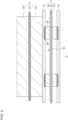
- FIG. 2 is a magnified sectional view of part of the electrode group 2 according to the first embodiment.
- FIG. 2 illustrates a cross section in a direction perpendicular to a longitudinal direction of the electrode group 2 before being wound.
- the electrode group 2 includes the positive plate 6, the negative plate 8, and the separator 10.
- the positive plate 6 has a structure in which a positive electrode mixture layer 30 is laminated onto a positive current collector 28.
- the negative plate 8 has a structure in which a negative electrode mixture layer 34 is laminated onto a negative current collector 32.
- the separator 10 is disposed between the positive plate 6 and the negative plate 8.
- the electrode group 2 also includes spacers 36 and low porosity portions 38.
- Each spacer 36 is interposed between the negative plate 8 and the separator 10 to form a space 40 between the negative plate 8 and the separator 10.
- This space 40 can accommodate lithium metal that deposits on the negative plate 8 when the secondary battery 1 is charged. In other words, lithium metal deposits within the space 40. This can suppress the expansion of the electrode group 2 due to the deposition of lithium metal.
- Each spacer 36 is a column or convex portion protruding from a surface of the negative plate 8 toward the separator 10 or from a surface of the separator 10 toward the negative plate 8.
- the spacers 36 are constituted by multiple resin blocks. Examples of the resin constituting the spacers 36 include olefin resin, acrylic resin, polyamide resin, polyimide resin, silicone resin, and epoxy resin.
- the spacers 36 suitably have a smaller porosity than the separator 10.
- the spacers 36 are structured such that multiple resin blocks are arranged at predetermined intervals in an in-plane direction of the separator 10, in other words, a direction in which the separator 10 extends.
- Each resin block may be of polygonal (e.g., hexagonal) or linear shape when viewed from a laminating direction of the negative plate 8 and the separator 10.
- the area of portions where the spacers 36 overlap with the separator 10 may suitably be 30% or less of the total area of the separator 10.
- An average height, or the dimension in the laminating direction of the negative plate 8 and the separator 10, of each spacer 36 may be in the range from 15 um to 120 um inclusive, for example.
- Each low porosity portion 38 is fitted into the separator 10 in an area where the separator 10 and a spacer 36 overlap when viewed from the laminating direction of the separator 10 and the negative plate 8. That is, at least part of each low porosity portion 38 is located inside the separator 10, with respect to the surface of the separator 10 in an area where the spacers 36 are not provided. Each low porosity portion 38 is interposed between the separator 10 and a spacer 36.
- the low porosity portions 38 have a smaller porosity than the separator 10. Examples of a constituent material of the low porosity portions 38 may be similar to those of a constituent material of the spacers 36.
- each low porosity portion 38 When viewed from an in-plane direction of the separator 10, the dimension in the in-plane direction of each low porosity portion 38 may suitably be 50% or greater of the dimension in the in-plane direction of each resin block. Also, the fitting depth of the portion of each low porosity portion 38 fitted into the separator 10 may suitably be 10% or greater of the thickness of the separator 10.
- a low porosity portion 38 is constituted by a portion where pores in the separator 10 are closed up.
- Each low porosity portion 38 in the present embodiment is constituted by a portion where pores in the separator 10 are filled with the constituent material of the spacers 36.
- the secondary battery 1 including such a low porosity portion 38 can be obtained using the following producing method, for example.
- FIG. 3A through FIG. 3D are diagrams that show a method for producing the secondary battery 1 according to the first embodiment.
- constituent material ink 36a of the spacers 36 is applied to a surface of the separator 10 that is to face the negative plate 8.
- the constituent material ink 36a is a solution in which the resin constituting the spacers 36 is dispersed in a publicly-known solvent.
- a publicly-known method may be employed, such as gravure printing, dispenser printing, and screen printing.
- part of the constituent material ink 36a is infiltrated into pores in the separator 10.
- the constituent material ink 36a is then dried.
- the spacers 36 protruding from the surface of the separator 10 are formed.
- the infiltrated constituent material ink 36a fills pores in the separator 10, so that the pores are closed up, and the low porosity portions 38 are formed.
- FIG. 4A is a scanning electron microscope (SEM) photograph of an ink-unapplied area in the separator 10.
- FIG. 4B is a SEM photograph of an ink-applied area in the separator 10.
- SEM scanning electron microscope
- FIG. 4A in an area where the constituent material ink 36a is not applied in the separator 10, a large number of pores 10a can be seen within the separator 10.
- FIG. 4B in an area where the constituent material ink 36a is applied in the separator 10, some of the pores 10a are closed up by the constituent material ink 36a, and a low porosity portion 38 is formed within the separator 10.
- a spacer 36 integrated with the low porosity portion 38 protrudes from a surface S of the separator 10.
- the positive plate 6 and the negative plate 8 are prepared.
- Each separator 10 is oriented such that the spacers 36 face the negative plate 8 side.
- a separator 10, the negative plate 8, a separator 10, and the positive plate 6 are laminated in this order.
- the electrode group 2 is obtained.
- the electrode group 2 is wound in a spiral shape and housed together with the non-aqueous electrolyte in the exterior can 4.
- the sealing plate 26 is fitted into the exterior can 4, so that the secondary battery 1 is obtained.
- the secondary battery 1 includes a separator 10 interposed between the negative plate 8 and a separator 10. Accordingly, a space 40 can be formed between the negative plate 8 and the separator 10, which sandwich spacers 36. By providing the space 40 between the negative plate 8 and the separator 10, lithium metal can be made to deposit within the space 40 when the secondary battery 1 is charged. Therefore, the expansion of the electrode group 2 due to the deposition of lithium metal can be suppressed.
- the secondary battery 1 includes the low porosity portions 38, having a smaller porosity than the separator 10, that each are fitted into the separator 10 in an area where the separator 10 and a spacer 36 overlap when viewed from the laminating direction of the separator 10 and the negative plate 8.
- the low porosity portions 38 are not provided, lithium ions in the non-aqueous electrolyte can reach the interface between the separator 10 and each spacer 36 through the pores 10a in the separator 10. Accordingly, lithium metal may deposit at the interface between the separator 10 and each spacer 36.
- the expansion of the electrode group 2 due to the deposition of lithium metal at the interface is difficult to absorb in the space 40.
- providing a low porosity portion 38 at a position in the separator 10 that overlaps a spacer 36 can inhibit the lithium ions from reaching the interface between the separator 10 and the spacer 36.
- the deposition of lithium metal at the interface can be suppressed, so that the expansion of the electrode group 2 can be further suppressed. Therefore, the quality of the secondary battery 1, such as durability, reliability, and safety, can be improved.
- lithium metal tends to deposit on the negative plate 8 more easily. Therefore, providing the low porosity portions 38 is particularly effective in lithium secondary batteries and can improve the quality while achieving higher energy density of the secondary battery 1.
- each low porosity portion 38 of the present embodiment is constituted by a portion where pores 10a in the separator 10 are closed up. This can suppress an increase in the number of parts caused by providing the low porosity portions 38 and can also prevent the complication of the manufacturing process of the secondary battery 1. Also, each low porosity portion 38 has a structure in which pores 10a in the separator 10 are filled with the constituent material of the spacers 36. Therefore, the low porosity portions 38 can be formed more easily. Also, the spacers 36 of the present embodiment have a smaller porosity than the separator 10. This can restrain lithium ions from reaching the interface between the separator 10 and a spacer 36 through the inside of the spacer 36. Therefore, the expansion of the electrode group 2 can be further suppressed.
- the method for producing the secondary battery 1 includes applying the constituent material ink 36a of the spacers 36 to a surface of a separator 10, which faces the negative plate 8, and infiltrating part of the constituent material ink 36a into pores 10a in the separator 10, thereby forming a spacer 36 and a low porosity portion 38 at the same time. Therefore, the secondary battery 1 including the spacers 36 and the low porosity portions 38 can be produced more easily.
- the secondary battery 1 according to the second embodiment includes configurations in common with the secondary battery 1 in the first embodiment, except the structure of each low porosity portion 38 and the method for forming the low porosity portions 38.
- the secondary battery 1 according to the present embodiment will be described mainly for configurations different from those in the first embodiment, and description of configurations in common will be briefly given or may be omitted.
- Each low porosity portion 38 of the present embodiment is constituted by a portion where pores 10a in the separator 10 are collapsed.
- the collapsed portion means a portion where pores 10a are reduced in volume or lost due to deformation of walls that form the pores 10a.
- the secondary battery 1 including such a low porosity portion 38 can be obtained using the following producing method, for example.
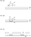
- FIG. 5A through FIG. 5C are diagrams that show a method for producing the secondary battery 1 according to the second embodiment.
- a constituent material sheet 36b of the spacers 36 is laminated onto a surface of the separator 10 that is to face the negative plate 8.
- the constituent material sheet 36b is a sheet (film) of the resin constituting the spacers 36.
- a die cutter 42 is pressed against an area of the constituent material sheet 36b where a spacer 36 is to be formed.
- the die cutter 42 includes a cutting blade 44 corresponding to the contour of a spacer 36, and a cushion member 46 disposed in a space enclosed by the cutting blade 44.
- the cushion member 46 is constituted by a flexible material, such as a silicone sheet.
- the length of a portion of the cutting blade 44 protruding from the cushion member 46 is set shorter than the thickness of the constituent material sheet 36b. Therefore, as shown in FIG. 5B , the constituent material sheet 36b is pressed against the separator 10 by the cushion member 46 and cut by the cutting blade 44. That is, when the cutting blade 44 enters a position where the constituent material sheet 36b is punched, the constituent material sheet 36b located within the cutting blade 44 is pressed by the cushion member 46. The constituent material sheet 36b pressed by the cushion member 46 then presses the separator 10.
- pores 10a are crushed and closed up, and a low porosity portion 38 is formed in a position that overlaps the spacer 36.
- the pressure applied by the die cutter 42 to the constituent material sheet 36b may be 1 MPa to 50 MPa, for example.
- an adhesive is applied to fix the constituent material sheet 36b to the separator 10. The adhesive may infiltrate into pores 10a when the constituent material sheet 36b is pressed against the separator 10 and may close up the pores 10a. Therefore, the low porosity portions 38 may be formed also by the infiltration of the adhesive.
- FIG. 6A is a SEM photograph of an unpressurized area of the separator 10.
- FIG. 6B is a SEM photograph of a pressurized area of the separator 10.
- FIG. 6A in an area where the constituent material sheet 36b is not pressed against the separator 10, a large number of pores 10a can be seen within the separator 10.
- FIG. 6B in an area where the constituent material sheet 36b is pressed against the separator 10, some of the pores 10a are crushed and closed up, and a low porosity portion 38 is formed within the separator 10.
- a separator 10 the negative plate 8, a separator 10, and the positive plate 6 are laminated and wound. Then, the electrode group 2 is sealed together with the non-aqueous electrolyte in the exterior can 4, obtaining the secondary battery 1.
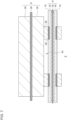
- FIG. 7 is a magnified sectional view of part of the electrode group 2 according to the first modification.
- the spacers 36 are interposed between the negative plate 8 and a separator 10 in the first and second embodiments, the spacers 36 may be interposed between the positive plate 6 and a separator 10 as shown in FIG. 7 .
- the space 40 is formed between the positive plate 6 and the separator 10.
- the separator 10 has moderate stretchability. Accordingly, when lithium metal deposits on the negative plate 8, the separator 10 is pressed by the lithium metal and expands toward the positive plate 6 side to enter the space 40. This can suppress the expansion of the electrode group 2.
- the spacers 36 may be interposed between each of the electrode plates of the negative plate 8 and the positive plate 6 and a separator 10.
- the spacer 36 When a spacer 36 is disposed between the negative plate 8 and the separator 10, the spacer 36 may be provided on the negative plate 8, a low porosity portion 38 may be provided in the separator 10, and then each electrode plate and the separator 10 may be laminated.
- the spacer 36 when a spacer 36 is disposed between the positive plate 6 and the separator 10, the spacer 36 may be provided on the positive plate 6, a low porosity portion 38 may be provided in the separator 10, and then each electrode plate and the separator 10 may be laminated.
- a low porosity portion 38 can be provided in the separator 10 by, for example, embedding a plate having a smaller porosity than the separator 10 into the separator 10.
- a low porosity portion 38 may be formed by providing a spacer 36 on an electrode plate or a separator 10, laminating the electrode plate, the spacer 36, and the separator 10, and applying pressure thereto, so that pores 10a in the separator 10 are collapsed by the spacer 36.
- the embodiments may be defined by the following Items.
- a secondary battery (1) including a positive plate (6), a negative plate (8), a separator (10), which is porous, disposed between the positive plate (6) and the negative plate (8), and a non-aqueous electrolyte, lithium metal depositing on the negative plate (8) during charging and the lithium metal dissolving in the non-aqueous electrolyte during discharge in the secondary battery (1), the secondary battery (1) including:
- the secondary battery (1) according to any one of Items 1 through 4, wherein the spacer (36) has a smaller porosity than the separator (10).
- the present disclosure is applicable to secondary batteries and methods for producing secondary batteries.
Landscapes
- Chemical & Material Sciences (AREA)
- Chemical Kinetics & Catalysis (AREA)
- Electrochemistry (AREA)
- General Chemical & Material Sciences (AREA)
- Engineering & Computer Science (AREA)
- Manufacturing & Machinery (AREA)
- Materials Engineering (AREA)
- Secondary Cells (AREA)
- Cell Separators (AREA)
Abstract
Description
- The present disclosure relates to a secondary battery and a method for producing a secondary battery.
- Lithium-ion batteries are known as high-capacity non-aqueous electrolyte secondary batteries. Also, as non-aqueous electrolyte secondary batteries having higher capacities than lithium-ion batteries, lithium secondary batteries (lithium metal secondary batteries) are known. In such a secondary battery, lithium metal deposits on the negative electrode during charging, which may cause the electrode group to expand and break. Meanwhile,
Patent Literature 1, for example, discloses a secondary battery in which a spacer is provided between the positive electrode and the separator so that a space for accommodating lithium metal is formed between the positive electrode and the negative electrode. - Patent Literature 1:
WO2020/066254 - The inventors have found a technology for further suppressing the expansion of the electrode group caused by lithium metal deposition and improving the quality of the secondary battery, such as durability and reliability.
- The present disclosure has been made in view of such a situation, and a purpose thereof is to provide a technology for improving the quality of secondary batteries.
- One embodiment of the present disclosure is a secondary battery that includes a positive plate, a negative plate, a separator, which is porous, disposed between the positive plate and the negative plate, and a non-aqueous electrolyte. In the secondary battery, lithium metal deposits on the negative plate during charging, and lithium metal dissolves in the non-aqueous electrolyte during discharge. The secondary battery includes: a spacer interposed between at least one of electrode plates of the negative plate and the positive plate and the separator to form a space between the electrode plate and the separator; and a low porosity portion that has a smaller porosity than the separator and that is fitted into the separator in an area where the separator and the spacer overlap when viewed from a laminating direction of the separator and the electrode plate.
- Another embodiment of the present disclosure is a method for producing a secondary battery that includes a positive plate, a negative plate, a separator, which is porous, disposed between the positive plate and the negative plate, and a non-aqueous electrolyte. In the secondary battery, lithium metal deposits on the negative plate during charging, and lithium metal dissolves in the non-aqueous electrolyte during discharge. The method for producing includes: applying constituent material ink of a spacer to at least one of a surface of the separator that faces the negative plate or a surface of the separator that faces the positive plate; and infiltrating part of the constituent material ink into a pore in the separator to form a spacer that forms a space between at least one of electrode plates of the negative plate and the positive plate and the separator and also to form a low porosity portion that has a smaller porosity than the separator and that is fitted into the separator in an area where the separator and the spacer overlap when viewed from a laminating direction of the separator and the electrode plate.
- Yet another embodiment of the present disclosure is a method for producing a secondary battery that includes a positive plate, a negative plate, a separator, which is porous, disposed between the positive plate and the negative plate, and a non-aqueous electrolyte. In the secondary battery, lithium metal deposits on the negative plate during charging, and lithium metal dissolves in the non-aqueous electrolyte during discharge. The method for producing includes: laminating a constituent material sheet of a spacer onto at least one of a surface of the separator that faces the negative plate or a surface of the separator that faces the positive plate; and pressing the constituent material sheet against the separator to collapse a pore in the separator and cutting the constituent material sheet to form a spacer that forms a space between at least one of electrode plates of the negative plate and the positive plate and the separator and also to form a low porosity portion that has a smaller porosity than the separator and that is fitted into the separator in an area where the separator and the spacer overlap when viewed from a laminating direction of the separator and the electrode plate.
- Optional combinations of the aforementioned constituting elements, and implementation of the present disclosure in the form of methods, apparatuses, or systems may also be practiced as additional modes of the present disclosure.
- According to the present disclosure, the quality of secondary batteries can be improved.
-
- [
FIG. 1] FIG. 1 is a sectional view of a secondary battery. - [
FIG. 2] FIG. 2 is a magnified sectional view of part of an electrode group according to a first embodiment. - [
FIGS. 3] FIG. 3A, FIG. 3B, FIG. 3C and FIG. 3D are diagrams that show a method for producing the secondary battery according to the first embodiment. - [
FIGS. 4] FIG. 4A is a SEM photograph of an ink-unapplied area of a separator.FIG. 4B is a SEM photograph of an ink-applied area of the separator. - [
FIGS. 5] FIG. 5A, FIG. 5B and FIG. 5C are diagrams that show a method for producing a secondary battery according to a second embodiment. - [
FIGS. 6] FIG. 6A is a SEM photograph of an unpressurized area of the separator.FIG. 6B is a SEM photograph of a pressurized area of the separator. - [
FIG. 7] FIG. 7 is a magnified sectional view of part of an electrode group according to a first modification. - In the following, the present disclosure will be described based on preferred embodiments with reference to the drawings. The embodiments are intended to be illustrative only and not to limit the present disclosure, so that it should be understood that not all of the features or combinations thereof described in the embodiments are necessarily essential to the present disclosure. Like reference characters denote like or corresponding constituting elements, members, and processes in each drawing, and repetitive description will be omitted as appropriate. Also, the scale or shape of each component shown in each drawing is defined for the sake of convenience to facilitate the explanation and is not to be regarded as limitative unless otherwise specified. Also, when the terms "first", "second", and the like are used in the present specification or claims, such terms do not imply any order or degree of importance and are used to distinguish one configuration from another, unless otherwise specified. Further, in each drawing, part of a member less important in describing the embodiments may be omitted.
-
FIG. 1 is a sectional view of asecondary battery 1. InFIG. 1 , illustration of aspacer 36 and alow porosity portion 38 is omitted. Thesecondary battery 1 is a battery in which lithium metal deposits on the negative plate during charging, and lithium metal dissolves in a non-aqueous electrolyte during discharge. Examples of such asecondary battery 1 include lithium-ion batteries and lithium secondary batteries. Thesecondary battery 1 as an example has a structure in which anelectrode group 2 is housed together with a non-aqueous electrolyte (not illustrated) in an exterior can 4. Theelectrode group 2 is cylindrical, for example, and has a wound structure in which apositive plate 6 of band shape and anegative plate 8 of band shape are laminated, with aseparator 10 of band shape provided therebetween, and wound in a spiral shape. - The
positive plate 6 has a structure in which a positive electrode mixture layer is laminated onto a positive current collector. The positive current collector is constituted by aluminum foil or the like. The positive electrode mixture layer can be formed by applying a positive electrode mixture to a surface of the positive current collector using a publicly-known coating device and by drying and rolling the positive electrode mixture. The positive electrode mixture is obtained by kneading materials, such as a positive electrode active material, a binding agent, and a conductive material, into a dispersion medium so that the materials are dispersed uniformly. The positive electrode active material may be, for example, a composite oxide containing lithium and a transition metal other than lithium. The lithium contained in the composite oxide is released as lithium ions from thepositive plate 6 during charging and deposits as lithium metal on thenegative plate 8. The lithium metal that has deposited dissolves during discharge, and lithium ions released at the time are occluded by the composite oxide of thepositive plate 6. - The
negative plate 8 has a structure in which a negative electrode mixture layer is laminated onto a negative current collector. The negative current collector is constituted by copper foil or the like. The negative electrode mixture layer can be formed by applying a negative electrode mixture to a surface of the negative current collector using a publicly-known coating device and by drying and rolling the negative electrode mixture. The negative electrode mixture is obtained by kneading materials, such as a negative electrode active material, a binding agent, and a conductive material, into a dispersion medium so that the materials are dispersed uniformly. The negative electrode active material may be graphite or the like in the case of a lithium-ion battery and may be lithium metal or the like in the case of a lithium secondary battery, for example. - The
positive plate 6 has a firstunapplied portion 12 on which the positive electrode mixture is not applied, at one end of a width direction, which is a direction intersecting a longitudinal direction of the band. Also, thenegative plate 8 has a secondunapplied portion 14 on which the negative electrode mixture is not applied, at the other end of the width direction, i.e., at the end opposite to the side where the firstunapplied portion 12 protrudes. - The
separator 10 is a porous member disposed between thepositive plate 6 and thenegative plate 8. As an example, a porous sheet having ion permeability and insulation properties is used for theseparator 10. The porous sheet may be a thin film having micropores, woven fabric, or non-woven fabric, for example. A constituent material of theseparator 10 may be, for example, a polymer material, such as olefin resin including polyethylene, polyamide resin, or cellulose. Theseparator 10 may contain an additive, such as an inorganic filler, as necessary. - On the side where the first
unapplied portion 12 protrudes in theelectrode group 2, a positivecurrent collector plate 20 is disposed. The positivecurrent collector plate 20 may be made of aluminum, for example. To the positivecurrent collector plate 20, the firstunapplied portion 12 is joined. On the side where the secondunapplied portion 14 protrudes in theelectrode group 2, a negativecurrent collector plate 22 is disposed. The negativecurrent collector plate 22 may be made of copper, nickel, nickel-plated copper, or nickel-plated iron, for example. To the negativecurrent collector plate 22, the secondunapplied portion 14 is joined. - The
electrode group 2 with the positivecurrent collector plate 20 and the negativecurrent collector plate 22 joined thereto is housed together with a non-aqueous electrolyte in the exterior can 4 of bottomed cylindrical shape. The non-aqueous electrolyte may be constituted by a publicly-known material having lithium ion conductivity. As an example, the non-aqueous electrolyte contains a non-aqueous solvent, such as an ester or an ether, and lithium ions dissolved in the non-aqueous solvent. The exterior can 4 may be made of copper, nickel, iron, or an alloy thereof, for example. The negativecurrent collector plate 22 is joined to an inner bottom surface of the exterior can 4 by welding or the like. The positivecurrent collector plate 20 is joined, by welding or the like, to a sealingplate 26 made of metal similar to the exterior can 4. The sealingplate 26 is fitted into an opening of the exterior can 4 via an insulatinggasket 24. Accordingly, theelectrode group 2 and the non-aqueous electrolyte are sealed inside the exterior can 4. - In the following, the structure of the
electrode group 2 will be described in detail.FIG. 2 is a magnified sectional view of part of theelectrode group 2 according to the first embodiment.FIG. 2 illustrates a cross section in a direction perpendicular to a longitudinal direction of theelectrode group 2 before being wound. As described previously, theelectrode group 2 includes thepositive plate 6, thenegative plate 8, and theseparator 10. Thepositive plate 6 has a structure in which a positiveelectrode mixture layer 30 is laminated onto a positivecurrent collector 28. Thenegative plate 8 has a structure in which a negativeelectrode mixture layer 34 is laminated onto a negativecurrent collector 32. Theseparator 10 is disposed between thepositive plate 6 and thenegative plate 8. - The
electrode group 2 also includesspacers 36 andlow porosity portions 38. Eachspacer 36 is interposed between thenegative plate 8 and theseparator 10 to form aspace 40 between thenegative plate 8 and theseparator 10. Thisspace 40 can accommodate lithium metal that deposits on thenegative plate 8 when thesecondary battery 1 is charged. In other words, lithium metal deposits within thespace 40. This can suppress the expansion of theelectrode group 2 due to the deposition of lithium metal. - Each
spacer 36 is a column or convex portion protruding from a surface of thenegative plate 8 toward theseparator 10 or from a surface of theseparator 10 toward thenegative plate 8. As an example, thespacers 36 are constituted by multiple resin blocks. Examples of the resin constituting thespacers 36 include olefin resin, acrylic resin, polyamide resin, polyimide resin, silicone resin, and epoxy resin. Thespacers 36 suitably have a smaller porosity than theseparator 10. - The
spacers 36 are structured such that multiple resin blocks are arranged at predetermined intervals in an in-plane direction of theseparator 10, in other words, a direction in which theseparator 10 extends. Each resin block may be of polygonal (e.g., hexagonal) or linear shape when viewed from a laminating direction of thenegative plate 8 and theseparator 10. When viewed from the laminating direction, the area of portions where thespacers 36 overlap with theseparator 10 may suitably be 30% or less of the total area of theseparator 10. An average height, or the dimension in the laminating direction of thenegative plate 8 and theseparator 10, of eachspacer 36 may be in the range from 15 um to 120 um inclusive, for example. - Each
low porosity portion 38 is fitted into theseparator 10 in an area where theseparator 10 and aspacer 36 overlap when viewed from the laminating direction of theseparator 10 and thenegative plate 8. That is, at least part of eachlow porosity portion 38 is located inside theseparator 10, with respect to the surface of theseparator 10 in an area where thespacers 36 are not provided. Eachlow porosity portion 38 is interposed between theseparator 10 and aspacer 36. Thelow porosity portions 38 have a smaller porosity than theseparator 10. Examples of a constituent material of thelow porosity portions 38 may be similar to those of a constituent material of thespacers 36. - When viewed from an in-plane direction of the
separator 10, the dimension in the in-plane direction of eachlow porosity portion 38 may suitably be 50% or greater of the dimension in the in-plane direction of each resin block. Also, the fitting depth of the portion of eachlow porosity portion 38 fitted into theseparator 10 may suitably be 10% or greater of the thickness of theseparator 10. - As an example, a
low porosity portion 38 is constituted by a portion where pores in theseparator 10 are closed up. Eachlow porosity portion 38 in the present embodiment is constituted by a portion where pores in theseparator 10 are filled with the constituent material of thespacers 36. Thesecondary battery 1 including such alow porosity portion 38 can be obtained using the following producing method, for example.FIG. 3A through FIG. 3D are diagrams that show a method for producing thesecondary battery 1 according to the first embodiment. - First, as shown in
FIG. 3A ,constituent material ink 36a of thespacers 36 is applied to a surface of theseparator 10 that is to face thenegative plate 8. As an example, theconstituent material ink 36a is a solution in which the resin constituting thespacers 36 is dispersed in a publicly-known solvent. For the application of theconstituent material ink 36a, a publicly-known method may be employed, such as gravure printing, dispenser printing, and screen printing. Thereafter, as shown inFIG. 3B , part of theconstituent material ink 36a is infiltrated into pores in theseparator 10. Theconstituent material ink 36a is then dried. Thus, thespacers 36 protruding from the surface of theseparator 10 are formed. Also, the infiltratedconstituent material ink 36a fills pores in theseparator 10, so that the pores are closed up, and thelow porosity portions 38 are formed. -
FIG. 4A is a scanning electron microscope (SEM) photograph of an ink-unapplied area in theseparator 10.FIG. 4B is a SEM photograph of an ink-applied area in theseparator 10. As shown inFIG. 4A , in an area where theconstituent material ink 36a is not applied in theseparator 10, a large number ofpores 10a can be seen within theseparator 10. On the other hand, as shown inFIG. 4B , in an area where theconstituent material ink 36a is applied in theseparator 10, some of thepores 10a are closed up by theconstituent material ink 36a, and alow porosity portion 38 is formed within theseparator 10. Also, aspacer 36 integrated with thelow porosity portion 38 protrudes from a surface S of theseparator 10. - Subsequently, as shown in
FIG. 3C , thepositive plate 6 and thenegative plate 8 are prepared. Eachseparator 10 is oriented such that thespacers 36 face thenegative plate 8 side. Then, aseparator 10, thenegative plate 8, aseparator 10, and thepositive plate 6 are laminated in this order. Accordingly, as shown inFIG. 3D , theelectrode group 2 is obtained. Theelectrode group 2 is wound in a spiral shape and housed together with the non-aqueous electrolyte in the exterior can 4. Then, the sealingplate 26 is fitted into the exterior can 4, so that thesecondary battery 1 is obtained. - As described above, the
secondary battery 1 according to the present embodiment includes aseparator 10 interposed between thenegative plate 8 and aseparator 10. Accordingly, aspace 40 can be formed between thenegative plate 8 and theseparator 10, whichsandwich spacers 36. By providing thespace 40 between thenegative plate 8 and theseparator 10, lithium metal can be made to deposit within thespace 40 when thesecondary battery 1 is charged. Therefore, the expansion of theelectrode group 2 due to the deposition of lithium metal can be suppressed. - Also, the
secondary battery 1 includes thelow porosity portions 38, having a smaller porosity than theseparator 10, that each are fitted into theseparator 10 in an area where theseparator 10 and aspacer 36 overlap when viewed from the laminating direction of theseparator 10 and thenegative plate 8. When thelow porosity portions 38 are not provided, lithium ions in the non-aqueous electrolyte can reach the interface between theseparator 10 and eachspacer 36 through thepores 10a in theseparator 10. Accordingly, lithium metal may deposit at the interface between theseparator 10 and eachspacer 36. However, the expansion of theelectrode group 2 due to the deposition of lithium metal at the interface is difficult to absorb in thespace 40. - On the other hand, providing a
low porosity portion 38 at a position in theseparator 10 that overlaps aspacer 36 can inhibit the lithium ions from reaching the interface between theseparator 10 and thespacer 36. As a result, the deposition of lithium metal at the interface can be suppressed, so that the expansion of theelectrode group 2 can be further suppressed. Therefore, the quality of thesecondary battery 1, such as durability, reliability, and safety, can be improved. In particular, in a lithium secondary battery containing lithium metal in the negativeelectrode mixture layer 34, lithium metal tends to deposit on thenegative plate 8 more easily. Therefore, providing thelow porosity portions 38 is particularly effective in lithium secondary batteries and can improve the quality while achieving higher energy density of thesecondary battery 1. - Also, each
low porosity portion 38 of the present embodiment is constituted by a portion wherepores 10a in theseparator 10 are closed up. This can suppress an increase in the number of parts caused by providing thelow porosity portions 38 and can also prevent the complication of the manufacturing process of thesecondary battery 1. Also, eachlow porosity portion 38 has a structure in which pores 10a in theseparator 10 are filled with the constituent material of thespacers 36. Therefore, thelow porosity portions 38 can be formed more easily. Also, thespacers 36 of the present embodiment have a smaller porosity than theseparator 10. This can restrain lithium ions from reaching the interface between theseparator 10 and aspacer 36 through the inside of thespacer 36. Therefore, the expansion of theelectrode group 2 can be further suppressed. - Also, the method for producing the
secondary battery 1 according to the present embodiment includes applying theconstituent material ink 36a of thespacers 36 to a surface of aseparator 10, which faces thenegative plate 8, and infiltrating part of theconstituent material ink 36a intopores 10a in theseparator 10, thereby forming aspacer 36 and alow porosity portion 38 at the same time. Therefore, thesecondary battery 1 including thespacers 36 and thelow porosity portions 38 can be produced more easily. - The
secondary battery 1 according to the second embodiment includes configurations in common with thesecondary battery 1 in the first embodiment, except the structure of eachlow porosity portion 38 and the method for forming thelow porosity portions 38. In the following, thesecondary battery 1 according to the present embodiment will be described mainly for configurations different from those in the first embodiment, and description of configurations in common will be briefly given or may be omitted. - Each
low porosity portion 38 of the present embodiment is constituted by a portion wherepores 10a in theseparator 10 are collapsed. The collapsed portion means a portion wherepores 10a are reduced in volume or lost due to deformation of walls that form thepores 10a. Thesecondary battery 1 including such alow porosity portion 38 can be obtained using the following producing method, for example.FIG. 5A through FIG. 5C are diagrams that show a method for producing thesecondary battery 1 according to the second embodiment. - First, as shown in
FIG. 5A , aconstituent material sheet 36b of thespacers 36 is laminated onto a surface of theseparator 10 that is to face thenegative plate 8. As an example, theconstituent material sheet 36b is a sheet (film) of the resin constituting thespacers 36. Then, adie cutter 42 is pressed against an area of theconstituent material sheet 36b where aspacer 36 is to be formed. Thedie cutter 42 includes acutting blade 44 corresponding to the contour of aspacer 36, and acushion member 46 disposed in a space enclosed by thecutting blade 44. As an example, thecushion member 46 is constituted by a flexible material, such as a silicone sheet. - The length of a portion of the
cutting blade 44 protruding from thecushion member 46 is set shorter than the thickness of theconstituent material sheet 36b. Therefore, as shown inFIG. 5B , theconstituent material sheet 36b is pressed against theseparator 10 by thecushion member 46 and cut by thecutting blade 44. That is, when thecutting blade 44 enters a position where theconstituent material sheet 36b is punched, theconstituent material sheet 36b located within thecutting blade 44 is pressed by thecushion member 46. Theconstituent material sheet 36b pressed by thecushion member 46 then presses theseparator 10. - As a result, pores 10a are crushed and closed up, and a
low porosity portion 38 is formed in a position that overlaps thespacer 36. In the portion of theconstituent material sheet 36b pressed by thecushion member 46, deformation in an in-plane direction of theconstituent material sheet 36b is restricted by thecutting blade 44. This enables the pressure applied by thecushion member 46 to theconstituent material sheet 36b to be transmitted to theseparator 10 more easily. Therefore, pores 10a can be collapsed more certainly. The pressure applied by thedie cutter 42 to theconstituent material sheet 36b may be 1 MPa to 50 MPa, for example. Also, to the surface of theconstituent material sheet 36b, an adhesive is applied to fix theconstituent material sheet 36b to theseparator 10. The adhesive may infiltrate intopores 10a when theconstituent material sheet 36b is pressed against theseparator 10 and may close up thepores 10a. Therefore, thelow porosity portions 38 may be formed also by the infiltration of the adhesive. - Thereafter, as shown in
FIG. 5C , unnecessary portions of theconstituent material sheet 36b other than thespacers 36 are peeled off from theseparator 10. Through the process described above, thespacers 36 protruding from a surface of theseparator 10 and thelow porosity portions 38 structured to includecollapsed pores 10a can be formed on theseparator 10. -
FIG. 6A is a SEM photograph of an unpressurized area of theseparator 10.FIG. 6B is a SEM photograph of a pressurized area of theseparator 10. As shown inFIG. 6A , in an area where theconstituent material sheet 36b is not pressed against theseparator 10, a large number ofpores 10a can be seen within theseparator 10. On the other hand, as shown inFIG. 6B , in an area where theconstituent material sheet 36b is pressed against theseparator 10, some of thepores 10a are crushed and closed up, and alow porosity portion 38 is formed within theseparator 10. - Thereafter, as in the first embodiment, a
separator 10, thenegative plate 8, aseparator 10, and thepositive plate 6 are laminated and wound. Then, theelectrode group 2 is sealed together with the non-aqueous electrolyte in the exterior can 4, obtaining thesecondary battery 1. - Embodiments of the present disclosure have been described in detail. The abovementioned embodiments merely describe specific examples for carrying out the present disclosure. The embodiments are not intended to limit the technical scope of the invention, and various design modifications, including changes, addition, and deletion of constituting elements, may be made to the embodiments without departing from the spirit of the present disclosure defined in the claims. Such an additional embodiment with a design modification added has the effect of each of the combined embodiments and modifications. In the aforementioned embodiments, matters to which design modifications may be made are emphasized with the expression of "of the present embodiment", "in the present embodiment", or the like. However, design modifications may also be made to matters without such expression. Also, optional combinations of the constituting elements included in each embodiment may also be employed as additional modes of the present disclosure. Further, the hatching provided on the cross sections in the drawings does not limit the materials of the objects with the hatching.
-
FIG. 7 is a magnified sectional view of part of theelectrode group 2 according to the first modification. Although thespacers 36 are interposed between thenegative plate 8 and aseparator 10 in the first and second embodiments, thespacers 36 may be interposed between thepositive plate 6 and aseparator 10 as shown inFIG. 7 . In this case, thespace 40 is formed between thepositive plate 6 and theseparator 10. Theseparator 10 has moderate stretchability. Accordingly, when lithium metal deposits on thenegative plate 8, theseparator 10 is pressed by the lithium metal and expands toward thepositive plate 6 side to enter thespace 40. This can suppress the expansion of theelectrode group 2. Also in the case where thespacers 36 are arranged between thepositive plate 6 and theseparator 10, forming thelow porosity portions 38 by infiltrating theconstituent material ink 36a as described in the first embodiment or forming thelow porosity portions 38 by pressing theconstituent material sheet 36b as described in the second embodiment can be employed. - The
spacers 36 may be interposed between each of the electrode plates of thenegative plate 8 and thepositive plate 6 and aseparator 10. When aspacer 36 is disposed between thenegative plate 8 and theseparator 10, thespacer 36 may be provided on thenegative plate 8, alow porosity portion 38 may be provided in theseparator 10, and then each electrode plate and theseparator 10 may be laminated. Similarly, when aspacer 36 is disposed between thepositive plate 6 and theseparator 10, thespacer 36 may be provided on thepositive plate 6, alow porosity portion 38 may be provided in theseparator 10, and then each electrode plate and theseparator 10 may be laminated. In these cases, alow porosity portion 38 can be provided in theseparator 10 by, for example, embedding a plate having a smaller porosity than theseparator 10 into theseparator 10. Alternatively, alow porosity portion 38 may be formed by providing aspacer 36 on an electrode plate or aseparator 10, laminating the electrode plate, thespacer 36, and theseparator 10, and applying pressure thereto, so thatpores 10a in theseparator 10 are collapsed by thespacer 36. - The embodiments may be defined by the following Items.
- A secondary battery (1) including a positive plate (6), a negative plate (8), a separator (10), which is porous, disposed between the positive plate (6) and the negative plate (8), and a non-aqueous electrolyte, lithium metal depositing on the negative plate (8) during charging and the lithium metal dissolving in the non-aqueous electrolyte during discharge in the secondary battery (1), the secondary battery (1) including:
- a spacer (36) interposed between at least one of electrode plates of the negative plate (8) and the positive plate (6) and the separator (10) to form a space (40) between the electrode plate and the separator (10); and
- a low porosity portion (38) that has a smaller porosity than the separator (10) and that is fitted into the separator (10) in an area where the separator (10) and the spacer (36) overlap when viewed from a laminating direction of the separator (10) and the electrode plate.
- The secondary battery (1) according to
Item 1, wherein the low porosity portion (38) is constituted by a portion where a pore (10a) in the separator (10) is closed up. - The secondary battery (1) according to
Item 2, wherein the low porosity portion (38) is constituted by a portion where a pore (10a) in the separator (10) is filled with a constituent material of the spacer (36). - The secondary battery (1) according to
Item 2, wherein the low porosity portion (38) is constituted by a portion where a pore (10a) in the separator (10) is collapsed. - The secondary battery (1) according to any one of
Items 1 through 4, wherein the spacer (36) has a smaller porosity than the separator (10). - A method for producing a secondary battery (1) including a positive plate (6), a negative plate (8), a separator (10), which is porous, disposed between the positive plate (6) and the negative plate (8), and a non-aqueous electrolyte, lithium metal depositing on the negative plate (8) during charging and the lithium metal dissolving in the non-aqueous electrolyte during discharge in the secondary battery (1), the method including:
- applying constituent material ink (36a) of a spacer (36) to at least one of a surface of the separator (10) that faces the negative plate (8) or a surface of the separator (10) that faces the positive plate (6); and
- infiltrating part of the constituent material ink (36a) into a pore (10a) in the separator (10) to form a spacer (36) that forms a space (40) between at least one of electrode plates of the negative plate (8) and the positive plate (6) and the separator (10) and also to form a low porosity portion (38) that has a smaller porosity than the separator (10) and that is fitted into the separator (10) in an area where the separator (10) and the spacer (36) overlap when viewed from a laminating direction of the separator (10) and the electrode plate.
- A method for producing a secondary battery (1) including a positive plate (6), a negative plate (8), a separator (10), which is porous, disposed between the positive plate (6) and the negative plate (8), and a non-aqueous electrolyte, lithium metal depositing on the negative plate (8) during charging and the lithium metal dissolving in the non-aqueous electrolyte during discharge in the secondary battery (1), the method including:
- laminating a constituent material sheet (36b) of a spacer (36) onto at least one of a surface of the separator (10) that faces the negative plate (8) or a surface of the separator (10) that faces the positive plate (6); and
- pressing the constituent material sheet (36b) against the separator (10) to collapse a pore (10a) in the separator (10) and cutting the constituent material sheet (36b) to form a spacer (36) that forms a space (40) between at least one of electrode plates of the negative plate (8) and the positive plate (6) and the separator (10) and also to form a low porosity portion (38) that has a smaller porosity than the separator (10) and that is fitted into the separator (10) in an area where the separator (10) and the spacer (36) overlap when viewed from a laminating direction of the separator (10) and the electrode plate.
- The present disclosure is applicable to secondary batteries and methods for producing secondary batteries.
- 1 secondary battery, 6 positive plate, 8 negative plate, 10 separator, 10a pore, 36 spacer, 36a constituent material ink, 36b constituent material sheet, 38 low porosity portion, 40 space
Claims (7)
- A secondary battery comprising a positive plate, a negative plate, a separator, which is porous, disposed between the positive plate and the negative plate, and a non-aqueous electrolyte, lithium metal depositing on the negative plate during charging and the lithium metal dissolving in the non-aqueous electrolyte during discharge in the secondary battery, the secondary battery comprising:a spacer interposed between at least one of electrode plates of the negative plate and the positive plate and the separator to form a space between the electrode plate and the separator; anda low porosity portion that has a smaller porosity than the separator and that is fitted into the separator in an area where the separator and the spacer overlap when viewed from a laminating direction of the separator and the electrode plate.
- The secondary battery according to Claim 1, wherein the low porosity portion is constituted by a portion where a pore in the separator is closed up.
- The secondary battery according to Claim 2, wherein the low porosity portion is constituted by a portion where a pore in the separator is filled with a constituent material of the spacer.
- The secondary battery according to Claim 2, wherein the low porosity portion is constituted by a portion where a pore in the separator is collapsed.
- The secondary battery according to any one of Claims 1 through 4, wherein the spacer has a smaller porosity than the separator.
- A method for producing a secondary battery comprising a positive plate, a negative plate, a separator, which is porous, disposed between the positive plate and the negative plate, and a non-aqueous electrolyte, lithium metal depositing on the negative plate during charging and the lithium metal dissolving in the non-aqueous electrolyte during discharge in the secondary battery, the method comprising:applying constituent material ink of a spacer to at least one of a surface of the separator that faces the negative plate or a surface of the separator that faces the positive plate; andinfiltrating part of the constituent material ink into a pore in the separator to form a spacer that forms a space between at least one of electrode plates of the negative plate and the positive plate and the separator and also to form a low porosity portion that has a smaller porosity than the separator and that is fitted into the separator in an area where the separator and the spacer overlap when viewed from a laminating direction of the separator and the electrode plate.
- A method for producing a secondary battery comprising a positive plate, a negative plate, a separator, which is porous, disposed between the positive plate and the negative plate, and a non-aqueous electrolyte, lithium metal depositing on the negative plate during charging and the lithium metal dissolving in the non-aqueous electrolyte during discharge in the secondary battery, the method comprising:laminating a constituent material sheet of a spacer onto at least one of a surface of the separator that faces the negative plate or a surface of the separator that faces the positive plate; andpressing the constituent material sheet against the separator to collapse a pore in the separator and cutting the constituent material sheet to form a spacer that forms a space between at least one of electrode plates of the negative plate and the positive plate and the separator and also to form a low porosity portion that has a smaller porosity than the separator and that is fitted into the separator in an area where the separator and the spacer overlap when viewed from a laminating direction of the separator and the electrode plate.
Applications Claiming Priority (2)
| Application Number | Priority Date | Filing Date | Title |
|---|---|---|---|
| JP2022018549 | 2022-02-09 | ||
| PCT/JP2023/004221 WO2023153447A1 (en) | 2022-02-09 | 2023-02-08 | Secondary battery and method for producing secondary battery |
Publications (2)
| Publication Number | Publication Date |
|---|---|
| EP4478471A1 true EP4478471A1 (en) | 2024-12-18 |
| EP4478471A4 EP4478471A4 (en) | 2025-09-03 |
Family
ID=87564463
Family Applications (1)
| Application Number | Title | Priority Date | Filing Date |
|---|---|---|---|
| EP23752911.0A Pending EP4478471A4 (en) | 2022-02-09 | 2023-02-08 | Secondary battery and method for producing a secondary battery |
Country Status (5)
| Country | Link |
|---|---|
| US (1) | US20250141051A1 (en) |
| EP (1) | EP4478471A4 (en) |
| JP (1) | JPWO2023153447A1 (en) |
| CN (1) | CN118661308A (en) |
| WO (1) | WO2023153447A1 (en) |
Families Citing this family (1)
| Publication number | Priority date | Publication date | Assignee | Title |
|---|---|---|---|---|
| WO2025070578A1 (en) * | 2023-09-28 | 2025-04-03 | パナソニックIpマネジメント株式会社 | Secondary battery |
Family Cites Families (4)
| Publication number | Priority date | Publication date | Assignee | Title |
|---|---|---|---|---|
| JPH1012279A (en) * | 1996-04-26 | 1998-01-16 | Denso Corp | Metal lithium secondary battery |
| EP3576186B1 (en) * | 2018-05-31 | 2023-05-31 | Panasonic Intellectual Property Management Co., Ltd. | Lithium secondary battery |
| CN112673504B (en) | 2018-09-28 | 2024-03-01 | 松下知识产权经营株式会社 | Lithium secondary battery |
| JP7813987B2 (en) * | 2020-08-31 | 2026-02-16 | パナソニックIpマネジメント株式会社 | Lithium secondary battery |
-
2023
- 2023-02-08 JP JP2023580302A patent/JPWO2023153447A1/ja active Pending
- 2023-02-08 US US18/835,506 patent/US20250141051A1/en active Pending
- 2023-02-08 EP EP23752911.0A patent/EP4478471A4/en active Pending
- 2023-02-08 CN CN202380015743.3A patent/CN118661308A/en active Pending
- 2023-02-08 WO PCT/JP2023/004221 patent/WO2023153447A1/en not_active Ceased
Also Published As
| Publication number | Publication date |
|---|---|
| US20250141051A1 (en) | 2025-05-01 |
| WO2023153447A1 (en) | 2023-08-17 |
| EP4478471A4 (en) | 2025-09-03 |
| JPWO2023153447A1 (en) | 2023-08-17 |
| CN118661308A (en) | 2024-09-17 |
Similar Documents
| Publication | Publication Date | Title |
|---|---|---|
| US20200212450A1 (en) | Electrode for solid state battery and solid state battery | |
| US9818996B2 (en) | Solid battery and method for manufacturing solid battery | |
| US9853274B2 (en) | Solid battery | |
| KR102440683B1 (en) | All-solid battery and method for manufacturing the same | |
| JP5187733B2 (en) | Manufacturing method of multilayer secondary battery | |
| JP5730442B2 (en) | Secondary battery with an insulating member | |
| US20120288736A1 (en) | Energy storage apparatus and method for manufacturing the same | |
| US10665889B2 (en) | Electrode stack and battery manufacturing method | |
| JP2015204247A (en) | Power storage device | |
| JPWO2015156276A1 (en) | Power storage device | |
| JP2000268813A (en) | Electrode structure of battery and capacitor, and method of manufacturing electrode | |
| EP4478471A1 (en) | Secondary battery and method for producing secondary battery | |
| JP2018088379A (en) | Bipolar electrode, method for manufacturing the same, and power storage divice | |
| US20240380061A1 (en) | Electrochemical cells with vents, and methods of manufacturing the same | |
| CN114843429B (en) | Electrodes and power storage devices | |
| CN113169315A (en) | Positive electrode structure for secondary battery | |
| EP3151304B1 (en) | Button cell on a lithium ion basis | |
| KR20230081657A (en) | Manufacturing method of secondary battery | |
| US20220158198A1 (en) | Solid-state battery | |
| KR102136599B1 (en) | Electrochemical device | |
| KR20180022706A (en) | Silicon monolithic graphite anode for lithium cell | |
| JP7755992B2 (en) | Secondary battery and method of manufacturing the same | |
| JP2018078041A (en) | Electrode plate of alkaline secondary battery, and alkaline secondary battery | |
| JP2021082754A (en) | Electrochemical device | |
| US20260088364A1 (en) | Laminated body, battery, and method of manufacturing laminate |
Legal Events
| Date | Code | Title | Description |
|---|---|---|---|
| STAA | Information on the status of an ep patent application or granted ep patent |
Free format text: STATUS: THE INTERNATIONAL PUBLICATION HAS BEEN MADE |
|
| PUAI | Public reference made under article 153(3) epc to a published international application that has entered the european phase |
Free format text: ORIGINAL CODE: 0009012 |
|
| STAA | Information on the status of an ep patent application or granted ep patent |
Free format text: STATUS: REQUEST FOR EXAMINATION WAS MADE |
|
| 17P | Request for examination filed |
Effective date: 20240621 |
|
| AK | Designated contracting states |
Kind code of ref document: A1 Designated state(s): AL AT BE BG CH CY CZ DE DK EE ES FI FR GB GR HR HU IE IS IT LI LT LU LV MC ME MK MT NL NO PL PT RO RS SE SI SK SM TR |
|
| DAV | Request for validation of the european patent (deleted) | ||
| DAX | Request for extension of the european patent (deleted) | ||
| REG | Reference to a national code |
Ref country code: DE Ref legal event code: R079 Free format text: PREVIOUS MAIN CLASS: H01M0010058000 Ipc: H01M0050491000 |
|
| A4 | Supplementary search report drawn up and despatched |
Effective date: 20250804 |
|
| RIC1 | Information provided on ipc code assigned before grant |
Ipc: H01M 50/491 20210101AFI20250729BHEP Ipc: H01M 4/04 20060101ALI20250729BHEP Ipc: H01M 4/38 20060101ALI20250729BHEP Ipc: H01M 10/0587 20100101ALI20250729BHEP Ipc: H01M 10/42 20060101ALI20250729BHEP Ipc: H01M 50/403 20210101ALI20250729BHEP Ipc: H01M 50/474 20210101ALI20250729BHEP Ipc: H01M 50/477 20210101ALI20250729BHEP Ipc: H01M 10/052 20100101ALI20250729BHEP |