EP4478465A2 - Isolierender referenzeinsatz - Google Patents
Isolierender referenzeinsatz Download PDFInfo
- Publication number
- EP4478465A2 EP4478465A2 EP24181123.1A EP24181123A EP4478465A2 EP 4478465 A2 EP4478465 A2 EP 4478465A2 EP 24181123 A EP24181123 A EP 24181123A EP 4478465 A2 EP4478465 A2 EP 4478465A2
- Authority
- EP
- European Patent Office
- Prior art keywords
- fuel cell
- cell plate
- insert
- flange
- passage
- Prior art date
- Legal status (The legal status is an assumption and is not a legal conclusion. Google has not performed a legal analysis and makes no representation as to the accuracy of the status listed.)
- Pending
Links
Images


Classifications
-
- H—ELECTRICITY
- H01—ELECTRIC ELEMENTS
- H01M—PROCESSES OR MEANS, e.g. BATTERIES, FOR THE DIRECT CONVERSION OF CHEMICAL ENERGY INTO ELECTRICAL ENERGY
- H01M8/00—Fuel cells; Manufacture thereof
- H01M8/24—Grouping of fuel cells, e.g. stacking of fuel cells
- H01M8/2465—Details of groupings of fuel cells
-
- H—ELECTRICITY
- H01—ELECTRIC ELEMENTS
- H01M—PROCESSES OR MEANS, e.g. BATTERIES, FOR THE DIRECT CONVERSION OF CHEMICAL ENERGY INTO ELECTRICAL ENERGY
- H01M8/00—Fuel cells; Manufacture thereof
- H01M8/10—Fuel cells with solid electrolytes
- H01M8/1016—Fuel cells with solid electrolytes characterised by the electrolyte material
- H01M8/1018—Polymeric electrolyte materials
- H01M8/1069—Polymeric electrolyte materials characterised by the manufacturing processes
-
- H—ELECTRICITY
- H01—ELECTRIC ELEMENTS
- H01M—PROCESSES OR MEANS, e.g. BATTERIES, FOR THE DIRECT CONVERSION OF CHEMICAL ENERGY INTO ELECTRICAL ENERGY
- H01M8/00—Fuel cells; Manufacture thereof
- H01M8/02—Details
- H01M8/0202—Collectors; Separators, e.g. bipolar separators; Interconnectors
-
- H—ELECTRICITY
- H01—ELECTRIC ELEMENTS
- H01M—PROCESSES OR MEANS, e.g. BATTERIES, FOR THE DIRECT CONVERSION OF CHEMICAL ENERGY INTO ELECTRICAL ENERGY
- H01M8/00—Fuel cells; Manufacture thereof
- H01M8/02—Details
- H01M8/0202—Collectors; Separators, e.g. bipolar separators; Interconnectors
- H01M8/0204—Non-porous and characterised by the material
- H01M8/0206—Metals or alloys
-
- H—ELECTRICITY
- H01—ELECTRIC ELEMENTS
- H01M—PROCESSES OR MEANS, e.g. BATTERIES, FOR THE DIRECT CONVERSION OF CHEMICAL ENERGY INTO ELECTRICAL ENERGY
- H01M8/00—Fuel cells; Manufacture thereof
- H01M8/10—Fuel cells with solid electrolytes
- H01M8/1004—Fuel cells with solid electrolytes characterised by membrane-electrode assemblies [MEA]
-
- H—ELECTRICITY
- H01—ELECTRIC ELEMENTS
- H01M—PROCESSES OR MEANS, e.g. BATTERIES, FOR THE DIRECT CONVERSION OF CHEMICAL ENERGY INTO ELECTRICAL ENERGY
- H01M8/00—Fuel cells; Manufacture thereof
- H01M8/24—Grouping of fuel cells, e.g. stacking of fuel cells
- H01M8/2455—Grouping of fuel cells, e.g. stacking of fuel cells with liquid, solid or electrolyte-charged reactants
-
- H—ELECTRICITY
- H01—ELECTRIC ELEMENTS
- H01M—PROCESSES OR MEANS, e.g. BATTERIES, FOR THE DIRECT CONVERSION OF CHEMICAL ENERGY INTO ELECTRICAL ENERGY
- H01M8/00—Fuel cells; Manufacture thereof
- H01M8/24—Grouping of fuel cells, e.g. stacking of fuel cells
- H01M8/2465—Details of groupings of fuel cells
- H01M8/247—Arrangements for tightening a stack, for accommodation of a stack in a tank or for assembling different tanks
- H01M8/2475—Enclosures, casings or containers of fuel cell stacks
-
- H—ELECTRICITY
- H01—ELECTRIC ELEMENTS
- H01M—PROCESSES OR MEANS, e.g. BATTERIES, FOR THE DIRECT CONVERSION OF CHEMICAL ENERGY INTO ELECTRICAL ENERGY
- H01M8/00—Fuel cells; Manufacture thereof
- H01M8/10—Fuel cells with solid electrolytes
- H01M2008/1095—Fuel cells with polymeric electrolytes
-
- Y—GENERAL TAGGING OF NEW TECHNOLOGICAL DEVELOPMENTS; GENERAL TAGGING OF CROSS-SECTIONAL TECHNOLOGIES SPANNING OVER SEVERAL SECTIONS OF THE IPC; TECHNICAL SUBJECTS COVERED BY FORMER USPC CROSS-REFERENCE ART COLLECTIONS [XRACs] AND DIGESTS
- Y02—TECHNOLOGIES OR APPLICATIONS FOR MITIGATION OR ADAPTATION AGAINST CLIMATE CHANGE
- Y02E—REDUCTION OF GREENHOUSE GAS [GHG] EMISSIONS, RELATED TO ENERGY GENERATION, TRANSMISSION OR DISTRIBUTION
- Y02E60/00—Enabling technologies; Technologies with a potential or indirect contribution to GHG emissions mitigation
- Y02E60/30—Hydrogen technology
- Y02E60/50—Fuel cells
Definitions
- the present invention relates, generally, to methods and systems for supporting a fuel cell stack, and more particularly, to systems and methods for supporting a fuel cell stack to minimize damage due to shocks, vibration, and short circuiting of a fuel cell stack system.
- Fuel cells electrochemically convert fuels and oxidants to electricity and heat and can be categorized according to the type of electrolyte (e.g., solid oxide, molten carbonate, alkaline, phosphoric acid, or solid polymer) used to accommodate ion transfer during operation. Moreover, fuel cell assemblies can be employed in many (e.g., automotive to aerospace to industrial to residential) environments, for multiple applications.
- electrolyte e.g., solid oxide, molten carbonate, alkaline, phosphoric acid, or solid polymer
- fuel cell assemblies can be employed in many (e.g., automotive to aerospace to industrial to residential) environments, for multiple applications.
- a Proton Exchange Membrane (hereinafter "PEM”) fuel cell converts the chemical energy of fuels such as hydrogen and oxidants such as air directly into electrical energy.
- the PEM is a sold polymer electrolyte that permits the passage of protons (i.e., H+ ions) from the "anode” side of the fuel cell to the "cathode” side of the fuel cell while preventing passage therethrough of reactant fluids (e.g., hydrogen and air gases).
- the Membrane Electrode Assembly (hereinafter “MEA”) is placed between two electrically conductive plates, each of which has a flow passage to direct the fuel to the anode side and oxidant to the cathode side of the PEM.
- Two or more fuel cells can be connected together to increase the overall power output of the assembly.
- the cells are connected in series, wherein one side of a plate serves as an anode plate for one cell and the other side of the plate is the cathode plate for the adjacent cell.
- BPP bipolar plates
- the anode plate of one cell is electrically connected to the separate cathode plate of an adjacent cell.
- these two plates are connected back-to-back and are often bonded together (e.g., bonded by adhesive, weld, or polymer). This bonded pair becomes as one, also commonly called a bipolar plate, since anode and cathode plates represent the positive and negative poles, electrically.
- the stack typically includes means for directing the fuel and the oxidant to the anode and cathode flow field channels, respectively.
- the stack usually includes a means for directing a coolant fluid to interior channels within the stack to absorb heat generated by the exothermic reaction of hydrogen and oxygen within the fuel cells.
- the stack generally includes means for exhausting the excess fuel and oxidant gases, as well as product water.
- the stack also includes an endplate, insulators, membrane electrode assemblies, gaskets, separator plates, electrical connectors, and collector plates, among other components, that are integrated together to form the working stack designed to produce electricity.
- the different plates may be abutted against each other and connected to each other to facilitate the performance of particular functions.
- a fuel cell plate may be utilized in a fuel cell stack to provide power in a variety of circumstances, such as in vehicles (e.g., commercial vehicles such as forklifts and passenger vehicles such as automobiles), buildings (e.g., as backup power for industrial, commercial, and residential structures), and in power storage (e.g., as long-term energy storage for a power grid).
- the fuel cell plate may be subject to physical forces (e.g., vibrations, blunt forces, and/or compressive forces) or electrical current/impulse which could damage the fuel cell plate and/or the fuel cell stack. Seismic activity could further cause such physical forces.
- the present invention provides, in a first aspect, a fuel cell plate which includes a first surface, a second surface opposite the first surface, a peripheral edge, an alignment hole spaced from the peripheral edge, and an insert received therein.
- the insert includes an annular portion which bounds a passage for receiving an aligning member and flanges extending radially from axial ends of the annular portion on the first surface and the second surface of the fuel cell plate.
- the present invention provides, in a second aspect, an insert which includes an annular body formed of an electrically insulating material.
- the annular body includes a radially exterior surface, a radially interior surface bounding a passage for receiving an aligning member, axial ends, and flanges located at the axial ends which bound a cavity for receiving a fuel cell plate.
- the flanges include a first flange and a second flange, the first flange including a beveled edge and a stopping edge extending radially from the radially exterior surface to form a catch.
- the catch and the annular body form an elastically deformable cantilever portion of an annular cantilever snap joint permitting insertion of the annular body into an alignment hole of the fuel cell plate.
- the present invention provides, in a third aspect, a method for use in assembling a fuel cell stack including inserting an insert into an alignment hole of a first fuel cell plate such that flanges of the insert extend radially from a body of the insert along opposite outside surfaces of a fuel cell plate.
- the alignment hole is spaced away from a periphery of the firs fuel cell plate and extends therethrough, and the insert is electrically insulating and bounds a first passage for receiving an aligning member therein.
- the fuel cell stack 20 may have an open cathode architecture of a PEM fuel cell, and combined oxidant and coolant, for example, air, may enter through an inlet air filter 10 couples to an inlet 5 of the fuel cell stack 20. Excess coolant/oxidant and heat may be exhausted from a fuel cell cathode of the fuel cell stack 20 through outlet 11 to the fan 40 which may exhaust the coolant/oxidant and/or excess fuel 18 to a waste exhaust 41, such as the ambient atmosphere.
- the fuel 13 and coolant/oxidant may be supplied by a fuel supply 7 and an oxidant source 9 (e.g., air), respectively, and other components of a balance of plant, which may include compressors, pumps, valves, fans, electrical connections, and sensors.
- FIG. 2 depicts an internal subassembly 100 of the fuel cell stack 20 of FIG. 1 including a cathodic end fluid flow plate 110 at an outer end 115 and a flow plate seal 120 on an inner side thereof.
- a membrane electrode assembly (MEA) 130 is located between the flow plate seal 120 and a second flow plate seal 150.
- An anode flow plate 160 is on a second end 165 of subassembly 100.
- the MEA 130 includes a membrane 140 between a cathode side catalyst layer 125 and an anode side catalyst layer 135.
- a cathode side gas diffusion layer (GDL) 122 is located between the cathode side catalyst layer 125 and the cathodic end fluid flow plate 110.
- An anode side gas diffusion layer 145 is located between the anode side catalyst layer 135 and the anode flow plate 160.
- the flow plate seal 120 and the second flow plate seal 150 may be received in a channel of an inner side of the cathodic end flow plate 110 and anode flow plate 160, respectively.
- FIG. 3 depicts a bipolar fuel cell plate 200, which could be a cathode plate (e.g., the cathodic end fluid flow plate 110) or an anode fluid flow plate (e.g., the anode flow plate 160).
- Fuel cell plate 200 has a body 202 comprising a first surface 204, a second surface 208 (visible in FIG. 5A ) opposite the first surface 204, and a peripheral edge 210 (visible in FIG. 9 ).
- the body 202 may have one or a plurality of alignment holes 214 located at various locations on the first surface 204 and the second surface 208 of the body 202 (e.g., near each of four opposite corners thereof) which are spaced away from the peripheral edge 210.
- the alignment holes 214 may extend through the body 202 to be in fluid communication with both the first surface 204 and the second surface 208.
- Each of the alignment holes 214 may be configured (e.g., shaped and dimensioned) to receive an insert 216.
- a first alignment hole 215 of the plurality of alignment holes 214 is identical to a second alignment hole 217 of the plurality of alignment holes 214.
- the first alignment hole 215 and the second alignment hole 217 may be of different shapes and/or sizes.
- a body (e.g., the body 202) of a fuel cell plate (e.g., the fuel cell plate 200) may include a plurality of alignment holes (e.g., the plurality of alignment holes 214) and a plurality of recessed portions 219 which may circumferentially surround one, some, or all openings 222 of the alignment holes 214 present on surfaces of the body (e.g., the first surface 204 and the second surface 208).
- a plurality of alignment holes e.g., the plurality of alignment holes 214
- a plurality of recessed portions 219 which may circumferentially surround one, some, or all openings 222 of the alignment holes 214 present on surfaces of the body (e.g., the first surface 204 and the second surface 208).
- a first recessed portion 218 of the plurality of recessed portions 219 located on the first surface 204 may be recessed relative to a first remaining portion 220 of the first surface 204 and may circumferentially surround and/or bound at least a first opening 223 of the first alignment hole 215.
- a second recessed portion 224 of the plurality of recessed portions 219 located on the second surface 208 may also be recessed relative to a second remaining portion 226 of the second surface 208 and may similarly circumferentially surround at least a second opening 225 of the first alignment hole 215.
- the insert 216 may be monolithically formed as depicted in FIGS. 4A and 4B .
- the insert 216 is injection molded.
- the insert 216 may also be configured for use with modern fuel cell plate designs (e.g., the fuel cell plate 200).
- the insert 216 may include an annular body 300 having a first axial end 302 and a second axial end 304.
- the annular body 300 of the insert 216 may be substantially annular or cylindrical to permit insertion of the insert 216 into one of the alignment holes 214 (e.g., the first alignment hole 215 or the second alignment hole 217).
- the insert 216 may be configured (e.g., shaped and dimensioned) in another shape where necessary to correspond with the shape of a reciprocal alignment hole (e.g., the second alignment hole 217).
- the annular body 300 may be tubular or hollow, including a radially exterior surface 306 and a radially interior surface 308.
- the radially interior surface 308 of the insert 216 may bound a passage 310 for receiving an aligning member 700 when the insert 216 is received in one of the alignment holes 214 (e.g., the first alignment hole 215) during assembly of the fuel cell stack 20 (partially depicted in FIG. 7 ).
- the passage 310 may also receive the aligning member 700 to hold the fuel cell plate 200 in place in various locations during various manufacturing processes.
- the first axial end 302 and the second axial end 304 are located at opposite axial ends of the annular body 300 as depicted in FIGS. 4A and 4B .
- the first axial end 302 bounds a first opening 328 of the passage 310
- the second axial end 304 bounds a second opening 330 of the passage 310.
- the first opening 328 and the second opening 330 have the same radius r value.
- the first opening 328 may have a larger radius r than the second opening 330.
- the radius r of the openings of the passage 310 may vary in different examples, at least one of the first opening 328 or the second opening 330 always has a radius r which is larger than a second radius r2 ( FIG. 7 ) of the aligning member 700 to permit insertion of the aligning member 700 therein.
- the aligning member 700 may be a bar or rod received in the passage 310 of the insert 216 by inserting the aligning member 700 into either the first opening 328 or second opening 330 of the passage 310. When fully inserted, the aligning member 700 may exit the opening opposite of that in which it was inserted, as partially depicted in FIGS. 7-9 .
- the aligning member 700 may be configured (e.g. shaped and dimensioned) to be received in the passage 310 and may be formed of a material (e.g.
- the aligning member 700 may be inserted into the first opening 328 or second opening 330 from an exterior of the body 202 and may be movable within the passage 310 in an axial direction (e.g., towards or away from the first opening 328 or second opening 330).
- Multiple instances of the insert 216 received in one or more alignment holes (e.g., the alignment holes 214) of one or more fuel cell plates (e.g., the fuel cell plate 200 and/or the second fuel cell plate 800) may allow multiple instances of the aligning member 700 to move axially within multiple instances of the passage 310.
- multiple instances of the insert 216 are identical.
- multiple instances of the aligning member 700 may be used to align and stack multiple instances of fuel cell plate 200 (or, similarly, to align and stack the fuel cell plate 200 and the second fuel cell plate 800) during assembly of the fuel cell stack 20.
- multiple instances of aligning member 700 may be received in openings (e.g., multiple instances of the first opening 328 and/or the second opening 330) of multiple instances of the passage 310 of multiple instances of the insert 216. In this way, multiple instances of fuel cell plate 200 may be stacked to form a fuel cell stack 20 using multiple instances of aligning member 700.
- the multiple instances of the aligning member 700 may be left in place to hold the multiple instances of the fuel cell plate 200 in position relative to each other in a stacking direction.
- such aligning member e.g., the aligning member 700
- a different aligning member may be inserted into the passage 310 of the insert 216.
- Such different aligning member may have different rigidity or different conductivity relative to the removed aligning member.
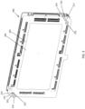
- the multiple instances of the fuel cell plate 200 may be aligned (e.g., vertically or in a stacking direction) along the peripheral edge 210 of the fuel cell plate 200 as depicted in FIG. 9 .
- the insert 216 may be formed of an electrically non-conductive material, for example, a plastic such as liquid crystal polymer E130i, such that a contact of insert 216 with aligning member 700 would not result in any electrical connection between the fuel cell plate 200 and the aligning member or any other fuel cell plate (e.g., multiple instances of the fuel cell plate 200 and/or the second fuel cell plate 800) which may be present in the fuel cell stack 20.
- a non-conductive material insulates the body 202 from electricity which may pass through the aligning member 700 during assembly of the fuel cell stack 20 and operation of the fuel cell system 101.
- the material used to form the insert 216 may also protect from mechanical damage that may occur due to contact of the aligning member 700 with the fuel cell plate 200, such as during assembly of the fuel cell stack 20 and operation of the fuel cell system 101.
- insert 216 may prevents or mitigate damage to the fuel cell plate 200, such as deformation of the body 202 and electrical shorting, which may otherwise result from interactions between the body 202 and the aligning member 700.
- insert 216 may be an electrical insulator to inhibit an any such shorting.
- Further insert 216 may have sufficient structure and rigidity to inhibit any damage that may be caused to body 202 by contact aligning member 700 with insert 216 and thus any pressure through insert 212 to body 202 via such contact.
- the insert 216 may be inserted into a previously bent or deformed alignment hole (not shown) to prevent further damage to a body of such a fuel cell plate with such deformation.
- insert 216 may inhibit any electrical shorts that may otherwise result through the use of such a deformed alignment hole with an alignment rod (e.g., alignment rod 700) .
- the receiving of the insert 216 into an already deformed alignment hole may thereby extend the lifespan of fuel cell plates (e.g., the fuel cell plate 200) by slowing or preventing continued deformation which can lead to a hard failure (e.g., such that the corresponding plate or fuel cell stack portion is not functional).
- Flanges 312 may extend from the first axial end 302 and the second axial end 304 of the annular body 300 as depicted in FIGS. 4A and 4B . Specifically, the flanges 312 may extend radially outwardly from the radially exterior surface 306 of the annular body 300. In some embodiments, the flanges 312 may be monolithically formed with the annular body 300. A first flange 314 of the flanges 312 may contact the first axial end 302 of the annular body 300 and extend radially therefrom. A second flange 316 of the flanges 312 may contact the second axial end 304 of the annular body 300 and may extend radially therefrom.
- the first flange may have a first outer side 320 and a first inner side 324
- the second flange 316 may have a second outer side 322 and a second inner side 326.
- the first flange 314 and second flange 316 may extend the same distance in a radial direction.
- the first flange 314 may extend further in a radial direction relative to the second flange 316.
- the first flange 314 and the second flange 316 may be of different shapes altogether.
- the insert 216 may include a cavity 318 for receiving the body 202 of the fuel cell plate 200 when the insert 216 is present in the first alignment hole 215, as shown in FIG. 5A .
- the cavity 318 may be bounded by the first inner side 324 of the first flange 314, the second inner side 326 of the second flange 316, and the radially exterior surface 306 of the annular body, such that the body 202 of the fuel cell plate 200 is located between (e.g., sandwiched by) the flanges 312 when the body 202 is in the cavity 318.
- Cavity 318 may be configured (e.g., shaped and dimensioned) such that a "snap fit" connection (described further below) may exist which may inhibit a disconnection between the insert 216 and the fuel cell plate 200 when the body 202 is received in the cavity 318.
- a "snap fit" connection (described further below) may exist which may inhibit a disconnection between the insert 216 and the fuel cell plate 200 when the body 202 is received in the cavity 318.
- the first inner side 324, the second inner side 326, and the radially exterior surface 306 may all be in contact with the body 202 when the body 202 is received in the cavity 318. However, in other embodiments, only the first inner side 324 and the second inner side 326 may be in contact with the body 202 when the body 202 is received in the cavity 318. In further embodiments, only one of the first inner side 324, the second inner side 326, or the radially exterior surface 306 may be in contact with the body 202 when the body 202 is received in the cavity 318. In even further embodiments, only the radially exterior surface and one of the first inner side 324 and second inner side 326 is in contact with the body 202 when the body 202 is received in the cavity 318.
- the first inner side 324 and/or second inner side 326 may be configured (e.g., shaped and dimensioned) to inhibit removal of the body 202 from the cavity 318 once the body 202 has been received in the cavity 318, similarly inhibiting removal of the insert 216 from the first alignment hole 215.
- the insert 216 may be configured to form a snap fit with the body 202 of the fuel cell plate 200, as explained in more detail below.
- at least one of the flanges 312 may be post-processed for a permanent fit against the fuel cell plate 200 to prevent removal of the body 202 from the cavity 318.
- Post-processing for a permanent fit may include the insert 216 being heat staked 602 to the body 202 on at least one of the flanges 312 as depicted in FIGS. 6 , which shows the insert heat staked through the fuel cell plate 200 to secure one of the flanges 312 (not visible) on the opposite side.
- first flange 314 may extend axially in the first recessed portion 218 such that the first outer side 320 of the first flange 314 is below the level of the first remaining portion 220 of the first surface 204.
- the first flange 314 may extend radially along the first recessed portion 218 such that the first flange 314 contacts the first remaining portion 220 of the first surface 204.
- the second flange 316 may similarly extend axially in the second recessed portion 224 such that the second outer side 322 of the second flange 316 is level (e.g., flush or aligned) with the second remaining portion 226 of the second surface 208.
- the second flange 316 may also extend axially in the second recessed portion 224 such that the second outer side 322 of the second flange 316 is below the level of the second remaining portion 226 of the second surface 208.
- a level transition between the first outer side 320 and the first remaining portion 220 and/or the second outer side 322 and the second remaining portion 226 allows for even distribution between the fuel cell plate 200 and the insert 216 of pressure, compression or other forces which may be applied to the fuel cell plate 200 during manufacturing and/or assembly of the fuel cell plate 200 into the fuel cell stack 20, and/or during operation of the fuel cell system 101, thus preventing and/or mitigating physical or mechanical damage and/or trauma thereto.
- the presence of the insert 216 in the alignment hole does not create additional or unwanted points of contact which may cause interference when compressive forces are applied during the process of stacking fuel cell plates (e.g., the fuel cell plate 200) during assembly of a fuel cell stack (e.g., the fuel cell stack 20).
- an insert may have opposite outer sides (e.g., the first outer side 320, the second outer side 322) that avoid extending axially outwardly past adjacent remaining portions (e.g., the first remaining portion 220, the second remaining portion 226) such that the insert avoids contacting an adjacent fuel cell plate (e.g., an instance of plate 200) when a fuel cell stack (e.g., the fuel cell stack 20) formed of such plates is assembled.
- Such insert e.g., insert 216) may thus avoid interfering with or contacting such plates when the plates are compressed or placed under load by securing members, such as bolts.
- the cavity 318 of insert 216 may further be configured (e.g., shaped and dimensioned) to connect the MEA 130 to the fuel cell plate 200 to allow a manipulation of a subassembly 900 of the fuel cell plate 200 and the MEA 130 during assembly of the fuel cell stack 20.
- Such a connection may be performed mechanically, such as MEA 130 being received in the cavity 318 of the insert 216, along with the body 202 of the fuel cell plate 200, to make a unitized fuel cell plate.
- Use of the insert 216 to create a unitized fuel cell plate may be facilitated by a snap fit connection as described below. The ability to unitize a fuel cell plate may reduce manufacturing times.
- non-constrained fuel cell assemblies in the prior art may not only take longer to manufacture, but may also make the MEA (e.g., the MEA 130) and fuel cell plate (e.g., the fuel cell plate 200) prone to damage caused by moving components.
- MEA e.g., the MEA 130
- fuel cell plate e.g., the fuel cell plate 200
- the second flange 316 may include a catch 350, as depicted in FIG. 5B , for example.
- the catch 350 may extend radially outwardly from the annular body 300 and includes a first beveled edge 352 and the second inner side 326 of the second flange 316.
- the first beveled edge 352 connects to the second inner side 326 at an angle y which may be any acute angle (e.g., a 45-degree angle).
- the catch 350 together with the annular body 300, form an annular cantilever which, together with one of the alignment holes 214 (e.g., the first alignment hole 215) of the body 202 forms an annular cantilever snap joint permitting the insertion of the insert 216 into one of the alignment holes 214 (e.g., the first alignment hole 215) and forming a snap fit inhibiting removal of the insert 216 therefrom.
- the first beveled edge 352 may be in contact with the first alignment hole 215 and may cause the force to be directed radially inwardly on the annular body 300 towards the passage 310.
- the annular body 300 may temporarily elastically deform (e.g., bend) radially inwards from a resting position into an elastically deformed position.
- the elastically deformed position may temporarily reduce the radius of the annular body 300 to allow at least the second flange 316 and the annular body 300 to fit through the first alignment hole 215.
- the radially inward force may be released, and the annular body 300 may elastically reform (e.g., elastically return or snap back) from the elastically deformed position into the resting position (i.e., the originally non-deformed position).
- the second inner side 326 of the second flange 316 may slide over the body 202 of the fuel cell plate 200 and act as a stopper, inhibiting axial movement of the insert 216 in a direction opposite of the direction in which it was inserted into one of the alignment holes 214 (e.g., the first alignment hole 215).
- the insert 216 may form a snap fit connection with the body 202 of the fuel cell plate 200 when the insert 216 is inserted into one of the alignment holes 214 (e.g., the first alignment hole 215).
- the first inner side 324 of the first flange 314 may inhibit removal or further movement of the insert 216 in the direction in which it was inserted into the first alignment hole 215.
- the insert 216 may also be formed of an elastically deformable material, for example, a plastic such as liquid crystal polymer E130i.
- an elastically deformable material may be necessary to permit the insert 216 to be inserted (via elastically deforming the insert 216) into one of the alignment holes 214 (e.g., the first alignment hole 215).
- the material used to form the insert 216 may only need to be as elastically deformable as is necessary to permit the insert 216 to be inserted into one of the alignment holes 214 and may otherwise have rigid qualities.
- the insert 216 may be formed of a sufficiently rigid material to permit the snap fit to be maintained between the insert 216 and the body 202 of the fuel cell plate 200.
- the insert 216 is formed of a material rigid enough to allow for the insert 216 to provide protection to the body 202 of the fuel cell plate 200 from damage which may result from blunt forces, compressive forces, vibrations, or other physical trauma which may be incurred by the fuel cell plate 200 during manufacture or during assembly into the fuel cell stack 20.
- Blunt forces may be applied to the fuel cell plate 200, for example, when the aligning member 700 is inserted into the passage 310.
- Compressive forces may be applied to the fuel cell plate 200, for example, during stacking of the fuel cell plate 200 with other fuel cell plates (which may or may not be identical to the fuel cell plate 200) during assembly of the fuel cell stack 20.
- the radially interior surface 308 of the annular body of the insert 216 may be configured (e.g., shaped and dimensioned) to guide the aligning member 700 through the passage 310.
- the radially interior surface 308 may comprise a flat annular middle portion 354, a second beveled edge 356, and a third beveled edge 358 as shown in FIG. 5A .
- the second beveled edge 356 and third beveled edge 358 may extend radially and outwardly on opposite sides of the flat annular middle portion 354, such that a radius (e.g., radius r) of the radially interior surface 308 is narrowest at the flat annular middle portion 354 and widens as it extends away from the flat annular middle portion 354.
- a radius e.g., radius r
- Such an embodiment may be employed where, for example, it is known that the aligning member 700 will only be inserted and/or removed from a single direction, in which case the second beveled edge 356 may be sufficient to obtain the full benefit of the insert 216.
- the aligning member 700 may contact either the second beveled edge 356 or the third beveled edge 358, and such contact with such edge may guide the aligning member 700 towards a center of the passage 310 and away from the body 202 of the fuel cell plate 200, thereby reducing the potential for the aligning member 700 to make contact with the body 202 of the fuel cell plate 200 and cause damage thereto.
- the radially interior surface 308 of the annular body 300 reduces the risk of damage which may result if the alignment member 700 were to contact the body 202 during manufacture of the fuel cell plate 200 or assembly of the fuel cell plate 200 into the fuel cell stack 20.
- the protection afforded to the fuel cell plate 200 by the presence of the insert 216 thereby addresses a problem in the prior art in which the nature of current designs make aligning members (e.g., the aligning member 700) prone to catching on fuel cell plates (e.g., the fuel cell plate 200) during manufacture and/or assembly into a fuel cell stack (e.g., the fuel cell stack 20), resulting in damage.
- aligning members e.g., the aligning member 700
- the insert 216 may be configured to enable tighter tolerances to aligning members (e.g., the aligning member 700) for better throughput in plate welding, gasketing, and stack assembly.
- aligning members e.g., the aligning member 700
- the radially interior surface 308 may contact the aligning member 700, holding the aligning member 700 and the body 202 of the fuel cell plate 200 in position relative to each other.
- the insert 216 acts as a buffer between the fuel cell plate 200 and the aligning member 700 which reduces the range of movement of the aligning member 700 within the passage 310, mitigating the risk of damage which may be caused by such movement.
- only the flat annular middle portion 354 of the radially interior surface 308 may abut the aligning member 700.
- insert 216 may be formed of a plastic or other non-conductive or non-metallic material. As can be seen in FIG. 7 , a connection of the insert 216 to the fuel cell plate 200 such that the body 202 of the fuel cell plate 200 is received in the cavity 318 of the insert 216 may allow contact of the aligning member 700 with the non-conductive material of the insert 216 during assembly of the fuel cell stack 20, and may similarly prevent contact between the aligning member 700 and the body 202 of the fuel cell plate 200.
- the non-conductive material may have properties such that a contact of such a non-conductive material with the aligning member 700 may have less of a frictional resistance therebetween than in a prior art situation where the fuel cell plate (e.g., the fuel cell plate 200) and the aligning member (e.g., the aligning member 700) are both formed of metal and are in direct contact with each other.
- the plates may be thin metal plates subject to being deformed by contact with the aligning member.
- a sliding of the insert 216 formed of non-conductive material or having a contacting portion formed of non-conductive material relative to the aligning member 700 may have less of a frictional resistance, and thus may be less likely to be damaged due to a catching or bending of the aligning member 700 relative to the insert 216, than in the case of where the contacting parts are made of metal.
Landscapes
- Engineering & Computer Science (AREA)
- Manufacturing & Machinery (AREA)
- Life Sciences & Earth Sciences (AREA)
- Sustainable Development (AREA)
- Sustainable Energy (AREA)
- Chemical & Material Sciences (AREA)
- Chemical Kinetics & Catalysis (AREA)
- Electrochemistry (AREA)
- General Chemical & Material Sciences (AREA)
- Fuel Cell (AREA)
Applications Claiming Priority (1)
| Application Number | Priority Date | Filing Date | Title |
|---|---|---|---|
| US18/335,516 US20240421333A1 (en) | 2023-06-15 | 2023-06-15 | Insulating datum insert |
Publications (2)
| Publication Number | Publication Date |
|---|---|
| EP4478465A2 true EP4478465A2 (de) | 2024-12-18 |
| EP4478465A3 EP4478465A3 (de) | 2025-04-16 |
Family
ID=91469909
Family Applications (1)
| Application Number | Title | Priority Date | Filing Date |
|---|---|---|---|
| EP24181123.1A Pending EP4478465A3 (de) | 2023-06-15 | 2024-06-10 | Isolierender referenzeinsatz |
Country Status (6)
| Country | Link |
|---|---|
| US (1) | US20240421333A1 (de) |
| EP (1) | EP4478465A3 (de) |
| JP (1) | JP2024180356A (de) |
| KR (1) | KR20240176453A (de) |
| AU (1) | AU2024203838A1 (de) |
| CA (1) | CA3241272A1 (de) |
Family Cites Families (5)
| Publication number | Priority date | Publication date | Assignee | Title |
|---|---|---|---|---|
| US6358641B1 (en) * | 1999-08-20 | 2002-03-19 | Plug Power Inc. | Technique and arrangement to align fuel cell plates |
| JP4422458B2 (ja) * | 2002-11-07 | 2010-02-24 | 本田技研工業株式会社 | 燃料電池 |
| ITMI20111263A1 (it) * | 2011-07-07 | 2013-01-08 | Menfi Ind S P A | Utensile di cottura |
| DE102014015219A1 (de) * | 2013-10-19 | 2015-04-23 | Daimler Ag | Ausrichtungsbestandteil und Verfahren zum Ausrichten in Brennstoffzellenstapeln |
| JP6800257B2 (ja) * | 2019-02-04 | 2020-12-16 | 本田技研工業株式会社 | 燃料電池スタック及び燃料電池スタックの組立方法 |
-
2023
- 2023-06-15 US US18/335,516 patent/US20240421333A1/en active Pending
-
2024
- 2024-06-06 AU AU2024203838A patent/AU2024203838A1/en active Pending
- 2024-06-10 EP EP24181123.1A patent/EP4478465A3/de active Pending
- 2024-06-10 CA CA3241272A patent/CA3241272A1/en active Pending
- 2024-06-13 KR KR1020240077222A patent/KR20240176453A/ko active Pending
- 2024-06-14 JP JP2024096470A patent/JP2024180356A/ja active Pending
Also Published As
| Publication number | Publication date |
|---|---|
| CA3241272A1 (en) | 2025-06-10 |
| US20240421333A1 (en) | 2024-12-19 |
| KR20240176453A (ko) | 2024-12-24 |
| EP4478465A3 (de) | 2025-04-16 |
| AU2024203838A1 (en) | 2025-01-09 |
| JP2024180356A (ja) | 2024-12-26 |
Similar Documents
| Publication | Publication Date | Title |
|---|---|---|
| CA2545132C (en) | Fuel cell stack | |
| US10665883B2 (en) | Separator for fuel cell and unit cell of fuel cell | |
| CA2522702C (en) | Fuel cell | |
| US11177491B2 (en) | Cell-monitoring connector and fuel cell having structure for detachably mounting the cell-monitoring connector thereon | |
| EP4478465A2 (de) | Isolierender referenzeinsatz | |
| CN114597465B (zh) | 燃料电池堆 | |
| US10547061B2 (en) | Fuel cell stack | |
| KR101856330B1 (ko) | 연료전지 셀 구조 | |
| KR101423614B1 (ko) | 연료전지용 막전극접합체 | |
| US20240072268A1 (en) | Fuel cell system | |
| US20240072270A1 (en) | System for supporting a fuel cell stack | |
| CA2953835C (en) | Fuel cell stack | |
| KR101655151B1 (ko) | 연료전지용 분리판 및 이를 포함하는 연료전지 스택 | |
| CN114171770B (zh) | 燃料电池 | |
| US12009559B2 (en) | Fuel cell stack | |
| US20240356047A1 (en) | Electrical connector systems and methods for connecting to a fuel cell stack | |
| US20250385280A1 (en) | Separator assembly to prevent corrosion of separator edge and fuel cell stack including the same | |
| JP2008108485A (ja) | 燃料電池 | |
| EP4523273A1 (de) | Integrierte schaltung für diagnosezwecke |
Legal Events
| Date | Code | Title | Description |
|---|---|---|---|
| PUAI | Public reference made under article 153(3) epc to a published international application that has entered the european phase |
Free format text: ORIGINAL CODE: 0009012 |
|
| STAA | Information on the status of an ep patent application or granted ep patent |
Free format text: STATUS: THE APPLICATION HAS BEEN PUBLISHED |
|
| AK | Designated contracting states |
Kind code of ref document: A2 Designated state(s): AL AT BE BG CH CY CZ DE DK EE ES FI FR GB GR HR HU IE IS IT LI LT LU LV MC ME MK MT NL NO PL PT RO RS SE SI SK SM TR |
|
| RIC1 | Information provided on ipc code assigned before grant |
Ipc: H01M 8/10 20160101ALN20241216BHEP Ipc: H01M 8/2465 20160101AFI20241216BHEP |
|
| PUAL | Search report despatched |
Free format text: ORIGINAL CODE: 0009013 |
|
| AK | Designated contracting states |
Kind code of ref document: A3 Designated state(s): AL AT BE BG CH CY CZ DE DK EE ES FI FR GB GR HR HU IE IS IT LI LT LU LV MC ME MK MT NL NO PL PT RO RS SE SI SK SM TR |
|
| RIC1 | Information provided on ipc code assigned before grant |
Ipc: H01M 8/10 20160101ALN20250312BHEP Ipc: H01M 8/2465 20160101AFI20250312BHEP |
|
| STAA | Information on the status of an ep patent application or granted ep patent |
Free format text: STATUS: REQUEST FOR EXAMINATION WAS MADE |
|
| 17P | Request for examination filed |
Effective date: 20251016 |