EP4478079A1 - Signalübertragungsverfahren und -vorrichtung - Google Patents
Signalübertragungsverfahren und -vorrichtung Download PDFInfo
- Publication number
- EP4478079A1 EP4478079A1 EP23765862.0A EP23765862A EP4478079A1 EP 4478079 A1 EP4478079 A1 EP 4478079A1 EP 23765862 A EP23765862 A EP 23765862A EP 4478079 A1 EP4478079 A1 EP 4478079A1
- Authority
- EP
- European Patent Office
- Prior art keywords
- sequence
- communication apparatus
- sending
- sequences
- sending mode
- Prior art date
- Legal status (The legal status is an assumption and is not a legal conclusion. Google has not performed a legal analysis and makes no representation as to the accuracy of the status listed.)
- Pending
Links
Images


Classifications
-
- G—PHYSICS
- G01—MEASURING; TESTING
- G01S—RADIO DIRECTION-FINDING; RADIO NAVIGATION; DETERMINING DISTANCE OR VELOCITY BY USE OF RADIO WAVES; LOCATING OR PRESENCE-DETECTING BY USE OF THE REFLECTION OR RERADIATION OF RADIO WAVES; ANALOGOUS ARRANGEMENTS USING OTHER WAVES
- G01S7/00—Details of systems according to groups G01S13/00, G01S15/00, G01S17/00
- G01S7/02—Details of systems according to groups G01S13/00, G01S15/00, G01S17/00 of systems according to group G01S13/00
- G01S7/28—Details of pulse systems
- G01S7/282—Transmitters
-
- H—ELECTRICITY
- H04—ELECTRIC COMMUNICATION TECHNIQUE
- H04L—TRANSMISSION OF DIGITAL INFORMATION, e.g. TELEGRAPHIC COMMUNICATION
- H04L1/00—Arrangements for detecting or preventing errors in the information received
- H04L1/12—Arrangements for detecting or preventing errors in the information received by using return channel
- H04L1/16—Arrangements for detecting or preventing errors in the information received by using return channel in which the return channel carries supervisory signals, e.g. repetition request signals
- H04L1/1607—Details of the supervisory signal
- H04L1/1642—Formats specially adapted for sequence numbers
-
- G—PHYSICS
- G01—MEASURING; TESTING
- G01S—RADIO DIRECTION-FINDING; RADIO NAVIGATION; DETERMINING DISTANCE OR VELOCITY BY USE OF RADIO WAVES; LOCATING OR PRESENCE-DETECTING BY USE OF THE REFLECTION OR RERADIATION OF RADIO WAVES; ANALOGOUS ARRANGEMENTS USING OTHER WAVES
- G01S13/00—Systems using the reflection or reradiation of radio waves, e.g. radar systems; Analogous systems using reflection or reradiation of waves whose nature or wavelength is irrelevant or unspecified
- G01S13/003—Bistatic radar systems; Multistatic radar systems
-
- G—PHYSICS
- G01—MEASURING; TESTING
- G01S—RADIO DIRECTION-FINDING; RADIO NAVIGATION; DETERMINING DISTANCE OR VELOCITY BY USE OF RADIO WAVES; LOCATING OR PRESENCE-DETECTING BY USE OF THE REFLECTION OR RERADIATION OF RADIO WAVES; ANALOGOUS ARRANGEMENTS USING OTHER WAVES
- G01S13/00—Systems using the reflection or reradiation of radio waves, e.g. radar systems; Analogous systems using reflection or reradiation of waves whose nature or wavelength is irrelevant or unspecified
- G01S13/02—Systems using reflection of radio waves, e.g. primary radar systems; Analogous systems
- G01S13/06—Systems determining position data of a target
- G01S13/08—Systems for measuring distance only
- G01S13/10—Systems for measuring distance only using transmission of interrupted, pulse modulated waves
- G01S13/22—Systems for measuring distance only using transmission of interrupted, pulse modulated waves using irregular pulse repetition frequency
-
- G—PHYSICS
- G01—MEASURING; TESTING
- G01S—RADIO DIRECTION-FINDING; RADIO NAVIGATION; DETERMINING DISTANCE OR VELOCITY BY USE OF RADIO WAVES; LOCATING OR PRESENCE-DETECTING BY USE OF THE REFLECTION OR RERADIATION OF RADIO WAVES; ANALOGOUS ARRANGEMENTS USING OTHER WAVES
- G01S13/00—Systems using the reflection or reradiation of radio waves, e.g. radar systems; Analogous systems using reflection or reradiation of waves whose nature or wavelength is irrelevant or unspecified
- G01S13/02—Systems using reflection of radio waves, e.g. primary radar systems; Analogous systems
- G01S13/06—Systems determining position data of a target
- G01S13/08—Systems for measuring distance only
- G01S13/10—Systems for measuring distance only using transmission of interrupted, pulse modulated waves
- G01S13/30—Systems for measuring distance only using transmission of interrupted, pulse modulated waves using more than one pulse per radar period
-
- G—PHYSICS
- G01—MEASURING; TESTING
- G01S—RADIO DIRECTION-FINDING; RADIO NAVIGATION; DETERMINING DISTANCE OR VELOCITY BY USE OF RADIO WAVES; LOCATING OR PRESENCE-DETECTING BY USE OF THE REFLECTION OR RERADIATION OF RADIO WAVES; ANALOGOUS ARRANGEMENTS USING OTHER WAVES
- G01S7/00—Details of systems according to groups G01S13/00, G01S15/00, G01S17/00
- G01S7/003—Transmission of data between radar, sonar or lidar systems and remote stations
- G01S7/006—Transmission of data between radar, sonar or lidar systems and remote stations using shared front-end circuitry, e.g. antennas
-
- G—PHYSICS
- G01—MEASURING; TESTING
- G01S—RADIO DIRECTION-FINDING; RADIO NAVIGATION; DETERMINING DISTANCE OR VELOCITY BY USE OF RADIO WAVES; LOCATING OR PRESENCE-DETECTING BY USE OF THE REFLECTION OR RERADIATION OF RADIO WAVES; ANALOGOUS ARRANGEMENTS USING OTHER WAVES
- G01S7/00—Details of systems according to groups G01S13/00, G01S15/00, G01S17/00
- G01S7/02—Details of systems according to groups G01S13/00, G01S15/00, G01S17/00 of systems according to group G01S13/00
- G01S7/023—Interference mitigation, e.g. reducing or avoiding non-intentional interference with other HF-transmitters, base station transmitters for mobile communication or other radar systems, e.g. using electro-magnetic interference [EMI] reduction techniques
- G01S7/0233—Avoidance by phase multiplex
-
- G—PHYSICS
- G01—MEASURING; TESTING
- G01S—RADIO DIRECTION-FINDING; RADIO NAVIGATION; DETERMINING DISTANCE OR VELOCITY BY USE OF RADIO WAVES; LOCATING OR PRESENCE-DETECTING BY USE OF THE REFLECTION OR RERADIATION OF RADIO WAVES; ANALOGOUS ARRANGEMENTS USING OTHER WAVES
- G01S7/00—Details of systems according to groups G01S13/00, G01S15/00, G01S17/00
- G01S7/02—Details of systems according to groups G01S13/00, G01S15/00, G01S17/00 of systems according to group G01S13/00
- G01S7/023—Interference mitigation, e.g. reducing or avoiding non-intentional interference with other HF-transmitters, base station transmitters for mobile communication or other radar systems, e.g. using electro-magnetic interference [EMI] reduction techniques
- G01S7/0234—Avoidance by code multiplex
-
- H—ELECTRICITY
- H04—ELECTRIC COMMUNICATION TECHNIQUE
- H04L—TRANSMISSION OF DIGITAL INFORMATION, e.g. TELEGRAPHIC COMMUNICATION
- H04L25/00—Baseband systems
- H04L25/02—Details ; arrangements for supplying electrical power along data transmission lines
-
- H—ELECTRICITY
- H04—ELECTRIC COMMUNICATION TECHNIQUE
- H04L—TRANSMISSION OF DIGITAL INFORMATION, e.g. TELEGRAPHIC COMMUNICATION
- H04L27/00—Modulated-carrier systems
- H04L27/26—Systems using multi-frequency codes
- H04L27/2601—Multicarrier modulation systems
- H04L27/2602—Signal structure
- H04L27/261—Details of reference signals
- H04L27/2613—Structure of the reference signals
-
- G—PHYSICS
- G01—MEASURING; TESTING
- G01S—RADIO DIRECTION-FINDING; RADIO NAVIGATION; DETERMINING DISTANCE OR VELOCITY BY USE OF RADIO WAVES; LOCATING OR PRESENCE-DETECTING BY USE OF THE REFLECTION OR RERADIATION OF RADIO WAVES; ANALOGOUS ARRANGEMENTS USING OTHER WAVES
- G01S13/00—Systems using the reflection or reradiation of radio waves, e.g. radar systems; Analogous systems using reflection or reradiation of waves whose nature or wavelength is irrelevant or unspecified
- G01S13/87—Combinations of radar systems, e.g. primary radar and secondary radar
Definitions
- Embodiments of this application relate to the communication field, and in particular, to a signal sending method and an apparatus.
- a radio detection and ranging (radio detection and ranging, Radar) (Radar for short) technology is one of the most frequently used radio sensing technologies currently. A principle thereof is described as follows: A radar transmits a sensing signal to specific space, the sensing signal is reflected to form an echo signal after reaching a target, and the radar receives the echo signal, and performs a correlation operation on the echo signal and the sensing signal to obtain spatial information of the target.
- a single-carrier waveform is a frequently used radar sensing waveform.
- the radar When the single-carrier waveform is used to perform sensing, the radar generates a single-carrier sensing signal based on a sequence.
- a correlation property of the single-carrier sensing signal is determined by using a correlation property of the sequence.
- the radar is usually required to generate a single-carrier sensing signal by using a sequence having a good auto correlation property.
- This application provides a signal sending method and an apparatus, so that a communication apparatus can send different sequences in different periodicities. In this way, sensing performance is improved.
- a signal sending method may be performed by a first communication apparatus, may be performed by a part of a first communication apparatus, for example, a processor, a chip, a chip system, or the like of the first communication apparatus, or may be implemented by a logic module or software that can implement all or a part of functions of a first communication apparatus.
- the method includes: determining N sequence sending modes, and sending a first signal based on a first sequence sending mode.
- the N sequence sending modes include the first sequence sending mode.
- the sequence sending modes indicate sending orders of N sequences, the N sequences are sent by the first communication apparatus in N periodicities, and N is a positive integer greater than 1.
- a cyclic shift value between sending orders indicated by any two adjacent sequence sending modes is 1.
- the first sequence sending mode is determined based on K second sequence sending modes and the N sequence sending modes, the N sequence sending modes include the K second sequence sending modes, the second sequence sending mode is a sequence sending mode corresponding to a second communication apparatus, and K is a positive integer.
- the first communication apparatus sends the first signal based on the first sequence sending mode in the N sequence sending modes. Because the sequence sending modes may indicate the sending orders of the N sequences, the sending of the first signal based on the first sequence sending mode may enable the first signal to carry (or include) N different sequences.
- the first signal is used for sensing, and the N sequences are not perfect auto correlation sequences, a ratio of an auto correlation side lobe to an auto correlation peak may be reduced. In this way, sensing accuracy is improved.
- the N sequences have poor cross-correlation, a ratio of a cross-correlation result to the auto correlation peak can be reduced. In this way, interference between different communication apparatuses is reduced.
- the first sequence sending mode may be determined based on at least one second sequence sending mode corresponding to the second communication apparatus, so that different communication apparatuses may use different sequences in a same periodicity. In this way, the interference between the different communication apparatuses is further reduced. In other words, according to the solution provided in this application, sensing performance can be improved by improving the sensing accuracy or reducing the interference between the different communication apparatuses.
- a cyclic shift value between the first sequence sending mode and the one second sequence sending mode is the largest. Based on the possible design, the first sequence sending mode having the largest cyclic shift value with the second sequence sending mode is selected, so that interference between the first communication apparatus and the second communication apparatus may be reduced as much as possible.
- a cyclic shift value between the first sequence sending mode and a target second sequence sending mode is the largest, where the target second sequence sending mode is a sequence sending mode whose corresponding interference power is the strongest in the K second sequence sending modes.
- the sequence sending mode whose corresponding interference power is the strongest causes greatest interference to the first communication apparatus. Therefore, the first sequence sending mode having the largest cyclic shift value with the target second sequence sending mode is selected, so that an interference degree may be reduced as much as possible. In this way, the sensing performance is improved.
- the N sequences are first-type sequences
- the n th sequence includes P repeated first-type sequences
- P is a positive integer greater than 1.
- a correlation operation performed on the first signal and an echo signal of the first signal may be a periodic auto correlation operation, so that a perfect or good periodic auto correlation property of the first-type sequence is properly used. This improves the sensing performance.
- the N sequences are second-type sequences
- the n th sequence includes P repeated second-type sequences
- a sending interval between the P repeated second-type sequences is greater than or equal to duration occupied for sending the second-type sequence
- P is a positive integer greater than 1.
- a correlation operation performed on the first signal and an echo signal of the first signal may be an aperiodic auto correlation operation, so that a perfect or good aperiodic auto correlation property of the first-type sequence is properly used. This improves the sensing performance.
- the method before the sending a first signal based on a first sequence sending mode, the method further includes: receiving a first sequence sent by the second communication apparatus, and determining the second sequence sending mode based on the first sequence.
- the first sequence is one of the N sequences.
- a 1 st sequence indicated by the second sequence sending mode is the first sequence.
- the receiving a first sequence sent by the second communication apparatus includes: monitoring, based on a first periodicity, a sequence sent by the second communication apparatus.
- the first sequence is a sequence detected in the first periodicity.
- the first periodicity is greater than or equal to sending duration of the first signal.
- the first periodicity is an interval between two adjacent times of monitoring.
- that the second sequence sending mode is a sequence sending mode corresponding to a second communication apparatus includes: the second sequence sending mode is a sequence sending mode used by the second communication apparatus; or the second sequence sending mode is a sequence sending mode obtained by performing cyclic shift on a sequence sending mode used by the second communication apparatus.
- the method further includes: receiving an echo signal of the first signal; performing an auto correlation operation based on the echo signal and the first signal; and determining a distance between the first communication apparatus and a target object based on an auto correlation operation result.
- the first communication apparatus is a radar, or the first communication apparatus is a terminal device or a network device having a radar function.
- the first signal is a signal used for radar ranging.
- the N sequences include one of an M sequence, a Gold sequence, a golay complementary pair GCP sequence, or an Ipatov sequence.
- a communication apparatus to implement various methods in the foregoing.
- the communication apparatus may be a first communication apparatus, or an apparatus included in a first communication apparatus, for example, a chip.
- the communication apparatus includes a corresponding module, unit, or means (means) for implementing the foregoing method.
- the module, unit, or means may be implemented by hardware, software, or hardware executing corresponding software.
- the hardware or the software includes one or more modules or units corresponding to the foregoing functions.
- the communication apparatus may include a processing module and a transceiver module.
- the transceiver module may also be referred to as a transceiver unit, and is configured to implement a sending function and/or a receiving function in any one of the foregoing aspects and any possible implementation of the foregoing aspects.
- the transceiver module may include a transceiver circuit, a transceiver machine, a transceiver, or a communication interface.
- the processing module may be configured to implement a processing function in any one of the foregoing aspects and any possible implementation of the foregoing aspects.
- the transceiver module includes a sending module and a receiving module, respectively configured to implement the sending function and the receiving function in any one of the foregoing aspects and any possible implementation of the foregoing aspects.
- a communication apparatus includes a processor and a memory.
- the memory is configured to store computer instructions.
- the processor executes the instructions, the communication apparatus is enabled to perform the method in any one of the foregoing aspects.
- the communication apparatus may be a first communication apparatus, or an apparatus included in a first communication apparatus, for example, a chip.
- a communication apparatus including a processor and a communication interface.
- the communication interface is configured to communicate with a module other than the communication apparatus.
- the processor is configured to execute a computer program or instructions, so that the communication apparatus performs the method in any one of the foregoing aspects.
- the communication apparatus may be a first communication apparatus, or an apparatus included in a first communication apparatus, for example, a chip.
- a communication apparatus including an interface circuit and a processor.
- the interface circuit is a code/data read/write interface circuit, and the interface circuit is configured to receive computer-executable instructions (where the computer-executable instructions are stored in a memory, and may be directly read from the memory, or may be read via another component) and transmit the computer-executable instructions to the processor.
- the processor is configured to execute the computer-executable instructions, so that the communication apparatus performs the method in any one of the foregoing aspects.
- the communication apparatus may be a first communication apparatus, or an apparatus included in a first communication apparatus, for example, a chip.
- a communication apparatus including at least one processor.
- the processor is configured to execute a computer program or instructions, so that the communication apparatus performs the method in any one of the foregoing aspects.
- the communication apparatus may be a first communication apparatus, or an apparatus included in a first communication apparatus, for example, a chip.
- the communication apparatus includes a memory, and the memory is configured to store necessary program instructions and data.
- the memory may be coupled to the processor, or may be independent of the processor.
- the communication apparatus may be a chip or a chip system.
- the apparatus may include a chip, or may include a chip and another discrete component.
- a computer-readable storage medium stores instructions. When the instructions are run on a communication apparatus, the communication apparatus is enabled to perform the method in any one of the foregoing aspects.
- a computer program product including instructions is provided.
- the communication apparatus is enabled to perform the method in any one of the foregoing aspects.
- the foregoing sending action/function may be understood as output information
- the foregoing receiving action/function may be understood as input information
- a character "/" indicates that associated objects are in an "or” relationship.
- A/B may represent A or B.
- a term “and/or” in this application merely describes an association relationship between associated objects and indicates that three relationships may exist.
- a and/or B may represent three cases: Only A exists, both A and B exist, or only B exists, where A and B may be singular or plural.
- a plurality of means two or more than two.
- At least one of the following items (pieces)" or a similar expression thereof refers to any combination of these items, including any combination of singular items (pieces) or plural items (pieces).
- at least one of a, b, or c may represent: a, b, c, a and b, a and c, b and c, and a and b and c, where a, b, and c may be singular or plural.
- words such as “first”, “second”, and the like are used in embodiments of this application to distinguish between same items or similar items that have basically same functions and purposes.
- a person skilled in the art may understand that the words such as “first”, “second”, and the like do not limit a quantity and an execution sequence, and the words such as “first”, “second”, and the like do not indicate a definite difference.
- the word “example”, “for example”, or the like is used to represent giving an example, an illustration, or a description. Any embodiment or design solution described as an “example” or “for example” in embodiments of this application should not be explained as being more preferred or having more advantages than another embodiment or design solution. Exactly, use of the word such as “example”, “for example”, or the like is intended to present a related concept in a specific manner for ease of understanding.
- an "embodiment” used throughout this specification means that particular features, structures, or characteristics related to this embodiment are included in at least one embodiment of this application. Therefore, embodiments in the entire specification are not necessarily a same embodiment. In addition, these particular features, structures, or characteristics may be combined in one or more embodiments in any proper manner. It may be understood that sequence numbers of the processes do not mean execution sequences in various embodiments of this application. The execution sequences of the processes should be determined based on functions and internal logic of the processes, and should not be construed as any limitation on implementation processes of embodiments of this application.
- some optional features in embodiments of this application may be independently implemented without depending on another feature, for example, a solution on which the optional features are currently based, to resolve a corresponding technical problem and achieve corresponding effects.
- the optional features may be combined with other features based on a requirement.
- an apparatus provided in embodiments of this application may also correspondingly implement these features or functions. Details are not described herein.
- a relative cyclic shift between the two sequences includes five possibilities in total: -2, -1, 0, 1, and 2.
- a periodic correlation result is: a 2 ⁇ b 1 + a 3 ⁇ b 2 + a 1 ⁇ b 3 .
- a periodic correlation result is: a 3 ⁇ b 1 + a 1 ⁇ b 2 + a 2 ⁇ b 3 .
- a periodic correlation result is: a 1 ⁇ b 1 + a 2 ⁇ b 2 + a 3 ⁇ b 3 .
- a periodic correlation result is: a 2 ⁇ b 1 + a 3 ⁇ b 2 + a 1 ⁇ b 3 .
- a periodic correlation result is: a 3 ⁇ b 1 + a 1 ⁇ b 2 + a 2 ⁇ b 3 .
- Aperiodic correlation operation When a correlation operation is performed on sequences, a correlation value of an overlapping element in two sequences is calculated based on a relative shift between the sequences. If lengths of the sequences are L , the relative shift between the sequences may include 2 L -1 cases in total: -L+ 1 , -L+2, ..., -1, 0, 1, ..., L -2, and L -1. Therefore, there are a total of 2 L -1 values for an aperiodic correlation operation of the sequences.
- a relative cyclic shift between the two sequences includes five possibilities in total: -2, -1, 0, 1, and 2.
- an aperiodic correlation result is: a 1 ⁇ b 3 .
- an aperiodic correlation result is: a 1 ⁇ b 2 + a 2 ⁇ b 3 .
- an aperiodic correlation result is: a 1 ⁇ b 1 + a 2 ⁇ b 2 + a 3 ⁇ b 3 .
- an aperiodic correlation result is: a 2 ⁇ b 1 + a 3 ⁇ b 2 .
- an aperiodic correlation result is: a 3 ⁇ b 1 .
- a correlation operation of the two sequences is a periodic correlation operation. If cyclic shift is not performed during relative shift, in other words, a quantity of overlapping elements of two sequences decreases as the relative shift increases, a correlation operation of the two sequences is an aperiodic correlation operation.
- Periodic auto correlation If two sequences are the same, a periodic correlation operation between the two sequences is referred to as periodic auto correlation.
- Periodic cross-correlation If two sequences are different, a periodic correlation operation between the two sequences is referred to as periodic cross-correlation.
- Aperiodic auto correlation If two sequences are the same, an aperiodic correlation operation between the two sequences is referred to as aperiodic auto correlation.
- Aperiodic cross-correlation If two sequences are different, the aperiodic correlation operation between the two sequences is referred to as aperiodic cross-correlation.
- Periodic cross-correlation peak For two sequences whose lengths are Z, a maximum value in absolute values of 2 L -1 periodic cross-correlation results of the two sequences is referred to as a periodic cross-correlation peak.
- Aperiodic cross-correlation peak For two sequences whose lengths are Z, a maximum value in absolute values of 2 L -1 aperiodic cross-correlation results of the two sequences is referred to as an aperiodic cross-correlation peak.
- an auto correlation result obtained when a shift is not 0 is referred to as an auto correlation side lobe in this application.
- a radar may generate a single-carrier sensing signal in a phase modulation manner. For example, as shown in FIG. 1 , a radar may send a pulse signal with a corresponding phase based on an element in a sequence. For example, when the element in the sequence is 1, a positive pulse is sent. When the element in the sequence is -1, a negative pulse is sent. Pulses corresponding to all elements in the sequence are superposed to obtain a broad pulse. The pulse may be a rectangular pulse, a Gaussian pulse, a root raised cosine pulse, or the like. This is not limited. In this generation manner, because shapes of pulses corresponding to different sequence elements are the same, a correlation property of the single-carrier sensing signal is determined by the sequence.
- the radar may send a sensing signal and receive an echo signal of the sensing signal, perform auto correlation calculation on the sensing signal and the echo signal, and determine information such as a distance of a target or the like by searching for a location at which a maximum auto correlation peak appears. If an auto correlation property of the sequence used when the sensing signal is generated is poor, an auto correlation side lobe may be large. This causes reduction of sensing accuracy. Therefore, to improve the sensing accuracy, a sequence is required to have a good auto correlation property.
- a sensing signal 1 sent by a radar 1 causes interference to a radar 2, and an echo that is in a direction of the radar 2 and that is obtained by reflecting the sensing signal 1 by a target also causes interference to the radar 2.
- a sensing signal 2 sent by the radar 2 causes interference to the radar 1, and an echo that is in a direction of the radar 1 and that is obtained by reflecting the sensing signal 2 by the target also causes interference to the radar 1.
- different radars usually use different sequences to generate sensing signals.
- a cross-correlation property between the different sequences determines a level of an interference signal. Therefore, to further reduce interference between radars, it is required that there be a good cross-correlation property between different sequences used by different radars.
- the M sequence, the Ipatov sequence, and the GCP sequence have good auto correlation properties, but poor cross-correlation properties.
- the Gold sequence has a good cross-correlation property, but a poor auto correlation property. Therefore, when an existing sequence is used to generate a single-carrier sensing signal, a sequence sending manner needs to be designed, to improve sensing performance.
- the GCP is a dual-channel sequence, has a perfect aperiodic auto correlation property, and is defined as follows. For a pair of sequences x and y whose code lengths are L, if a sum of aperiodic auto correlation functions (aperiodic auto correlation functions, AACFs) of the sequences is 0 at another shift location other than a 0 shift location, the sequences x and y are a piece of (pair of) GCP.
- AACFs aperiodic auto correlation functions
- a sensing signal usually includes a signal repeatedly sent in a plurality of periodicities, in other words, a sequence repeatedly sent by a transmitting end in a plurality of periodicities.
- a radar sends, in each periodicity of N periodicities, a signal generated based on a sequence S.
- the radar may send a pulse signal with a corresponding phase based on an element in the sequence S.
- the radar separately performs an auto correlation operation on a received signal (including an echo signal and noise) and a sensing signal for the N periodicities, to obtain N auto correlation results, and accumulates the N auto correlation results. Because total duration of the N periodicities is very small, and is generally in a nanosecond or microsecond level, it may be considered that a location of a sensed target in the N periodicities is not changed. Therefore, when the auto correlation operation is separately performed for the N periodicities, a location at which a maximum auto correlation peak appears in each periodicity is the same. After the N auto correlation results are accumulated, a maximum correlation peak may be increased by N times. In addition, noise is randomly distributed, and the noise does not increase after the accumulation. Therefore, an SNR of the receiving end can be increased in this sending manner.
- performing a correlation operation on a signal may also be understood as performing a correlation operation on a sequence used to generate the signal, or performing a correlation operation on a sequence carried in the signal.
- Sending a signal generated based on a sequence may also be understood as sending a sequence.
- a conventional solution that is, a signal generated based on a same Gold sequence is sent in N periodicities, and auto correlation results of the N periodicities are accumulated at a receiving end, because auto correlation results in all periodicities are the same, both an auto correlation peak and an auto correlation side lobe are increased by N times after the accumulation.
- a ratio of an auto correlation side lobe to an auto correlation peak is not changed.
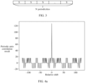
- FIG. 4a to FIG. 4c respectively show diagrams of simulation of periodic auto correlation results of a Gold sequence 1, a Gold sequence 2, and a Gold sequence 3. It can be learned from FIG. 4a to FIG. 4c that locations (at a 0 shift location) of auto correlation peaks of the Gold sequence 1, the Gold sequence 2, and the Gold sequence 3 are the same and values of the auto correlation peaks are equal, and auto correlation side lobes at another shift location have irregular values and are irregularly positive or negative. Therefore, if periodic auto correlation results of the three Gold sequences are accumulated, an auto correlation peak is increased by three times, and the auto correlation side lobes at the another shift location may increase or decrease.
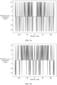
- FIG. 5a to FIG. 5c respectively show a periodic cross-correlation result of a Gold sequence 1 and a Gold sequence 2, a periodic cross-correlation result of the Gold sequence 1 and a Gold sequence 3, and a periodic cross-correlation result of the Gold sequence 2 and the Gold sequence 3. It can be learned from FIG. 5a to FIG. 5c that periodic cross-correlation results of the three pairs of sequences are different.
- a periodic cross-correlation value at each shift location may increase or decrease.
- a quantity of Gold sequences increases, it may be considered according to the law of large numbers that a periodic cross-correlation result after accumulation is not changed compared with that before the accumulation.
- each radar when a plurality of radars perform sensing, each radar sends, in N periodicities, signals generated based on different Gold sequences, and accumulates cross-correlation results in the N periodicities, and therefore a periodic cross-correlation result is not changed.
- a ratio of a periodic cross-correlation value to the auto correlation peak may be reduced. In other words, interference between radars is reduced.
- a radar 1 sends, in N periodicities, a signal generated based on a Gold sequence 1
- a radar 2 sends, in the N periodicities, a signal generated based on a Gold sequence 2.
- sequences which are the Gold sequence 1 and the Gold sequence 2 on which a cross-correlation operation is performed in each periodicity are the same
- a cross-correlation result is increased by N times after cross-correlation results in the N periodicities are accumulated.
- the auto correlation peak is also increased by N times. Therefore, compared with a case of sending a signal generated based on a Gold sequence once in one periodicity, the ratio of the cross-correlation result to the auto correlation peak is not changed, and the interference between radars is not reduced.
- signals generated based on different Gold sequences are sent in N periodicities. This can reduce a ratio of an auto correlation side lobe to an auto correlation peak, so that sensing accuracy is improved. This can also reduce a ratio of a cross-correlation result to an auto correlation peak, so that interference between different radars is reduced.
- Gold sequence 1 the Gold sequence 2, and the Gold sequence 3 are respectively as follows.
- the Gold sequence 1 is 1, 1, 1, 1, 1, 1, 1, 1, 1, 1, 1, 1, -1, 1, 1, 1, 1, -1, 1, 1, -1, 1, -1, 1, 1, 1, -1, -1, 1, 1, 1, 1, -1, -1, 1, -1, 1, -1, 1, -1, 1, -1, 1, -1, 1, -1, 1, -1, 1, -1, 1, -1, 1, -1, 1, -1, 1, -1, 1, -1, 1, -1, 1, -1, 1, 1,1,-1,1,-1, -1, -1, 1, -1, 1, -1, 1, -1, -1, 1, 1, 1, -1, -1, -1, 1, 1, 1, -1, -1, -1, 1, 1, 1, -1, -1, -1, 1, 1, 1, 1, -1, -1, -1, 1, 1, 1, 1, -1, 1, -1, -1, -1, -1, 1, 1, 1, 1, -1, 1, -1, -1, -1, -1, 1, 1, 1, 1, -1, 1, -1, 1, -1, -1, -1,
- the Gold sequence 2 is -1, 1, 1, 1, 1, 1, 1, -1, -1, 1, 1, -1, 1, -1, 1, -1, 1, -1, 1, -1, 1, -1, -1, 1, -1, -1, 1, 1, 1, 1, 1, -1, 1, 1, -1, -1, -1, 1, -1, 1, 1, 1, 1, 1, -1, 1, -1, -1, 1, -1, 1, 1, 1, 1, 1, -1, 1, -1, 1, -1, 1, 1, 1, 1, -1, 1, -1, 1, -1, 1, -1, 1, -1, 1, -1, 1, -1, 1, -1, 1, -1, 1, -1, 1, -1, 1, -1, 1, -1, 1, -1, 1, -1, 1, -1, 1, -1, 1, -1, 1, -1, 1, -1, 1, -1, 1, -1, 1, 1, -1, 1, 1, -1, 1, -1, 1, -1, 1, -1, 1, -1, 1, 1, -1, 1, -1, 1, -1, 1, -1, 1, -1, 1, -1
- the Gold sequence 3 is -1, 1, 1, 1, 1, 1, -1, 1, -1, 1, 1, -1, -1, -1, 1, -1, -1, 1, 1, -1, -1, -1, 1, 1, 1, 1, 1, 1, -1, 1, -1, 1, -1, 1, -1, 1, -1, 1, -1, 1, -1, 1, -1, 1, -1, 1, -1, 1, -1, 1, -1, 1, -1, 1, -1, 1, -1, 1, 1, 1, 1, 1, -1, 1, -1, 1, - 1, 1, 1, 1, -1, -1, 1, -1, -1, 1, 1, 1, 1, 1, -1, 1, 1, 1, 1, 1, -1, 1, 1, 1, 1, 1, 1, -1, 1, 1, 1, 1, 1, 1, -1, 1, 1, 1, 1, 1, -1, 1, 1, 1, 1, 1, -1, 1, 1, 1, 1, 1, -1, 1, 1, 1, 1, 1, -1, 1, 1, 1, 1, 1, -1, 1, 1, 1, 1, 1, -1, 1, 1, 1, 1, 1, -1, 1, 1, 1, 1, 1, -1, 1, 1, 1, 1, -1, 1, 1, 1,
- a sequence with a fixed auto correlation side lobe (for example, an absolute value is fixed to 0 or 1) like an M sequence, an Ipatov sequence, or a GCP sequence
- signals generated based on different sequences are sent in N periodicities, so that a ratio of a cross-correlation result to an auto correlation peak may be reduced.
- signals generated based on different sequences are sent in different periodicities, or different sequences are sent in different periodicities, so that sensing performance can be improved.
- different sequences may not be sent in different periodicities.
- group hopping and sequence hopping (Sequence hopping) solutions are defined in an existing 5th generation (5th generation, 5G) new radio (new radio, NR) protocol, to facilitate user equipment (user equipment, UE) to use different sequences in different slots.
- 5th generation, 5G new radio
- UE user equipment
- SRS sounding reference signal
- c init is determined by a number of the UE, and c init may be set to be equal to the number of the UE in actual application.
- n s represents a slot in the NR protocol, and represents an n s th periodicity in the sensing scenario.
- c init is determined by the number of the UE in the NR protocol, and may be determined by a number of a radar in the sensing scenario, or the like.
- the radar determines, based on the pseudo-random sequence, a sequence used in each periodicity. Therefore, the sequence sending manner is essentially a random sequence selection method. Therefore, in this solution, there is a probability that a same radar uses a same sequence in different periodicities, and there is also a probability that different radars use a same sequence in a same periodicity.
- this application provides a signal sending method, so that a same device sends different sequences in different periodicities, and different devices use different sequences in a same periodicity. This reduces a ratio of an auto correlation side lobe to an auto correlation peak, so that sensing accuracy is improved. Alternatively, this reduces a ratio of a cross-correlation result to an auto correlation peak, so that interference between different radars is reduced.
- the technical solution in embodiments of this application may be applied to various communication systems.
- the communication system may be a 3rd generation partnership project (3rd generation partnership project, 3GPP) communication system, for example, a 5G or 6th generation (sixth generation, 6G) mobile communication system or a sidelink (sidelink, SL) system, an ultra-wideband (ultra-wideband, UWB) system, a vehicle to everything (vehicle to everything, V2X) system, or a device-to-device (device-to-device, D2D) communication system, a machine-to-machine (machine-to-machine, M2M) communication system, an internet of things (internet of things, IoT), or another next generation communication system.
- the communication system may alternatively be a non-3GPP communication system, for example, a wireless local area network (wireless local area network, WLAN) system like Wi-Fi. This is not limited.
- the technical solution in embodiments of this application may be applied to various communication scenarios, for example, may be applied to one or more of the following communication scenarios: smart home, D2D, V2X, IoT communication scenarios, and the like.
- the communication system and the communication scenarios applicable to this application are merely examples for description.
- the communication system and the communication scenarios applicable to this application are not limited thereto. This is uniformly described herein. Details are not described below again.
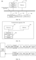
- FIG. 6 shows a communication system according to an embodiment of this application.
- the communication system includes at least two communication apparatuses.
- FIG. 6 an example in which a first communication apparatus and a second communication apparatus are included is used for description.
- the communication apparatus may send a signal based on a sequence.
- the communication apparatus may be a radar, or a terminal device or a network device having a radar function.
- the communication system may further include at least two target objects.
- FIG. 6 an example in which a target object 1 and a target object 2 are included is used for description.
- the signal sent by the communication apparatus may be used to sense the target object.
- the first communication apparatus may send a sensing signal 1 to sense the target object 1, and the second communication apparatus may send a sensing signal 2 to sense the target object 2.
- the first communication apparatus and the second communication apparatus may interfere with each other.
- Interference of one communication apparatus to another communication apparatus mainly includes two parts: one part is interference caused by a direct signal of the communication apparatus, and the other part is interference caused by reflecting a sensing signal by a target object. Therefore, a signal actually received by a communication apparatus is a superposition of an echo signal of the communication apparatus and an interference signal caused by another communication apparatus. In the solution of this application, interference between the two communication apparatuses is low.
- one of the first communication apparatus and the second communication apparatus may be a terminal device having a radar function, and the other may be a network device having a radar function; or both of the first communication apparatus and the second communication apparatus may be terminal devices having radar functions.
- the terminal device may be a device having a wireless transceiver function.
- the network device is a device that connects a terminal device to a wireless network.
- the network device may be a next generation NodeB (next generation NodeB, gNodeB or gNB) in a 5G system or a 6G system, may be a transmission reception point (transmission reception point, TRP), may be a base station in a future evolved public land mobile network (public land mobile network, PLMN). This is not specifically limited in this embodiment of this application.
- next generation NodeB next generation NodeB, gNodeB or gNB
- TRP transmission reception point
- PLMN public land mobile network
- the terminal device may also be referred to as UE, a terminal, an access terminal, a subscriber unit, a subscriber station, a mobile station (mobile station, MS), a remote station, a remote terminal, a mobile terminal (mobile terminal, MT), a user terminal, a wireless communication device, a user agent, a user apparatus, or the like.
- the terminal device may be, for example, an IoT, V2X, D2D, M2M, a 5G network, a 6G network, or a wireless terminal in a future evolved PLMN.
- the terminal device may be deployed on land, where the deployment includes indoor or outdoor, or handheld or vehicle-mounted deployment, may be deployed on water (for example, on a ship, or the like), or may be deployed in air (for example, on an airplane, a balloon, a satellite, or the like).
- the terminal device may be an uncrewed aerial vehicle, an IoT device (for example, a sensor, an electricity meter, a water meter, or the like), a V2X device, a station (station, ST) in a wireless local area network (wireless local area network, WLAN), a cellular phone, a cordless phone, a session initiation protocol (session initiation protocol, SIP) phone, a wireless local loop (wireless local loop, WLL) station, a personal digital processing (personal digital assistant, PDA) device, a hand-held device having a wireless communication function, a computing device or another processing device connected to a wireless modem, a vehicle-mounted device, a wearable device (which may also be referred to as a wearable intelligent device), a tablet computer or a computer having a wireless transceiver function, a virtual reality (virtual reality, VR) terminal, a terminal in industrial control (industrial control), a terminal in self-driving (self-driving), a terminal in remote
- first communication apparatus or the second communication apparatus in this application may be implemented by one device, may be jointly implemented by a plurality of devices, may be implemented by one or more function modules in one device, may be implemented by one or more chips, or may be implemented by a system on chip (system on chip, SoC) or a chip system.
- SoC system on chip
- the chip system may include a chip, or may include a chip and another discrete component. This is not specifically limited in this embodiment of this application.
- the foregoing function may be a network element in a hardware device, may be a software function running on dedicated hardware, a combination of hardware and software, or a virtualized function instantiated on a platform (for example, a cloud platform).
- FIG. 7a is a diagram of a structure of a communication apparatus 700 according to an embodiment of this application.
- the communication apparatus 700 includes one or more processors 701 and at least one communication interface (in FIG. 7a , only an example in which the communication interface 704 and one processor 701 are included is used for description), and optionally, may further include a communication line 702 and a memory 703.
- the processor 701 may be a general-purpose central processing unit (central processing unit, CPU), a microprocessor, an application-specific integrated circuit (application-specific integrated circuit, ASIC), or one or more integrated circuits configured to control program execution in the solution of this application.
- CPU central processing unit
- ASIC application-specific integrated circuit
- the processor 701 may include one or more CPUs, for example, a CPU 0 and a CPU 1 in FIG. 7a .
- the communication apparatus 700 may include a plurality of processors.
- processors may be a single-core (single-core) processor, or may be a multi-core (multi-core) processor.
- the processor herein may include but is not limited to at least one of the following: various computing devices that run software, such as a central processing unit (central processing unit, CPU), a microprocessor, a digital signal processor (DSP), a microcontroller unit (microcontroller unit, MCU), an artificial intelligence processor, or the like.
- CPU central processing unit
- DSP digital signal processor
- microcontroller unit microcontroller unit
- MCU microcontroller unit
- an artificial intelligence processor or the like.
- Each type of computing device may include one or more cores for executing software instructions to perform an operation or processing.
- the communication line 702 may be used for communication between different components included in the communication apparatus 700.
- the communication interface 704 may be configured to communicate with another device or communication network, for example, an Ethernet, a radio access network (wireless access network, RAN), a WLAN, or the like.
- the communication interface 704 may be an apparatus like a transceiver or a transceiver machine, or may be an input/output interface.
- the communication interface 704 may be a transceiver circuit located inside the processor 701, and is configured to implement signal input and signal output of the processor.
- the memory 703 may be an apparatus having a storage function.
- the memory may be a read-only memory (read-only memory, ROM) or another type of static storage device that can store static information and instructions, a random access memory (random access memory, RAM) or another type of dynamic storage device that can store information and instructions.
- ROM read-only memory
- RAM random access memory
- the memory may alternatively be an electrically erasable programmable read-only memory (electrically erasable programmable read-only memory, EEPROM), a compact disc read-only memory (compact disc read-only memory, CD-ROM) or another compact disk storage, an optical disk storage (including a compressed optical disc, a laser disc, an optical disc, a digital versatile disc, a Blu-ray disc, or the like), a magnetic disk storage medium or another magnetic storage device, or any other medium that can be configured to carry or store expected program code in a form of an instruction or a data structure and that can be accessed by a computer.
- the memory is not limited thereto.
- the memory may independently exist and is connected to the processor through the communication line 702.
- the memory may alternatively be integrated with the processor.
- the memory 703 may be configured to store computer-executable instructions for executing the solution of this application, and the execution is controlled by the processor 701, to implement the method provided in embodiments of this application.
- the processor 701 may perform a processing-related function in the method provided in the following embodiment of this application, and the communication interface 704 is responsible for a function of communicating with another device or communication network in the method provided in the following embodiment of this application. This is not specifically limited in this embodiment of this application.
- the computer-executable instructions in this embodiment of this application may also be referred to as application program code. This is not specifically limited in this embodiment of this application.
- the communication apparatus 700 may further include an output device 705 and an input device 706.
- the output device 705 communicates with the processor 701, and may display information in a plurality of manners.
- the output device 705 may be a liquid crystal display (liquid crystal display, LCD), a light emitting diode (light emitting diode, LED) display device, a cathode ray tube (cathode ray tube, CRT) display device, a projector (projector), or the like.
- the input device 706 communicates with the processor 701, and may receive an input from a user in a plurality of manners.
- the input device 706 may be a mouse, a keyboard, a touchscreen device, a sensing device, or the like.
- FIG. 7b is a diagram of a structure of another communication apparatus 700 according to an embodiment of this application.
- the communication apparatus 700 includes a processor 701 and a transceiver 704.
- FIG. 7b shows only main parts of the communication apparatus 700.
- the communication apparatus may further include a memory 703 and an input/output apparatus (which is not shown in the figure).
- the processor 701 is mainly configured to: process a communication protocol and communication data, control the entire communication apparatus, execute a software program, and process data of the software program.
- the memory 703 is mainly configured to store the software program and data.
- the transceiver 704 may include a radio frequency circuit and an antenna.
- the radio frequency circuit is mainly configured to: perform conversion between a baseband signal and a radio frequency signal, and process the radio frequency signal.
- the antenna is mainly configured to receive and send a radio frequency signal in a form of an electromagnetic wave.
- the processor 701 may read the software program in the memory 703, interpret and execute instructions of the software program, and process the data of the software program.
- the processor 701 When needing to send data wirelessly, after performing baseband processing on the to-be-sent data, the processor 701 outputs a baseband signal to the radio frequency circuit; and the radio frequency circuit performs radio frequency processing on the baseband signal and then sends a radio frequency signal to the outside in a form of an electromagnetic wave through the antenna.
- the radio frequency circuit receives a radio frequency signal through the antenna, converts the radio frequency signal into a baseband signal, and outputs the baseband signal to the processor 701.
- the processor 701 converts the baseband signal into data, and processes the data.
- the radio frequency circuit and the antenna may be disposed independent of the processor that performs baseband processing.
- the radio frequency circuit and the antenna may be remotely disposed independent of the communication apparatus.
- the processor 701 in FIG. 7b may include a digital signal processor, a signal generator, and an analog-to-digital converter.
- a radio frequency circuit configured to send a signal may include an up-converter and a power amplifier, and a radio frequency circuit configured to receive a signal may include a down-converter and a power amplifier.
- the antenna may include a transmit antenna and a receive antenna.
- the signal generator may be configured to generate a signal.
- the up-converter and the down-converter are respectively configured to modulate a signal to a high-frequency carrier and demodulate a signal from the high-frequency carrier.
- the power amplifier is configured to amplify power of a signal.
- the analog-to-digital converter is configured to convert a digital signal and an analog signal.
- the digital signal processor is configured to generate a sensing sequence and perform an auto correlation operation and/or a cross-correlation operation.
- composition structure shown in FIG. 7a, FIG. 7b, or FIG. 7c does not constitute any limitation on the communication apparatus.
- the communication apparatus may include more or fewer parts than those shown in the figure, a combination of some parts, or a different arrangement of the parts.
- the parts shown in the figure may be implemented by hardware, software, or a combination of software and hardware.
- an execution body may perform a part or all of the steps in embodiments of this application.
- the steps or operations are merely examples. Other operations or variations of various operations may alternatively be performed in embodiments of this application.
- the steps may be performed in a sequence different from a sequence presented in embodiments of this application, and not all the operations in embodiments of this application may be performed.
- FIG. 8 shows a signal sending method according to this application. Refer to FIG. 8 .
- the signal sending method includes the following steps.
- a first communication apparatus determines N sequence sending modes, where N is a positive integer greater than 1.
- the sequence sending modes indicate sending orders of N sequences. In other words, each sequence sending mode indicates one sending order of the N sequences. Different sequence sending modes indicate different sending orders of the N sequences.
- a sending order of the N sequences indicated by a sequence sending mode may also be understood as an arrangement order of the N sequences.
- the sending order and the arrangement order may be replaced with each other.
- the N sequences are sent by the first communication apparatus in N periodicities.
- a cyclic shift value between sending orders indicated by any two adjacent sequence sending modes is 1.
- a sending order indicated by one sequence sending mode is cyclically shifted by one bit to obtain a sending order indicated by the other sequence sending mode.
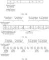
- numbers of the N sequences are respectively 1,2,3 ,...,N.
- a sending order indicated by a 1 st sequence sending mode in the N sequence sending modes may be: 1,2,3,..., N .
- the sequence 1, the sequence 2, the sequence 3, ..., and the sequence N are sequentially sent in the N periodicities.
- a sending order indicated by a 2 nd sequence sending mode in the N sequence sending modes may be 2,3,..., N, 1.
- the sequence 2, the sequence 3, ..., the sequence N, and the sequence 1 are sequentially sent in the N periodicities.
- a sending order indicated by a 3 rd sequence sending mode in the N sequence sending modes may be 3,..., N ,1, 2.
- the sequence 3, the sequence 4, ..., the sequence N, the sequence 1, and the sequence 2 are sequentially sent in the N periodicities.
- the sending orders indicated by the N sequence sending modes are respectively as follows:
- the sending order indicated by the sequence sending mode 1 is cyclically shifted leftward by one bit to obtain the sending order indicated by the sequence sending mode 2
- the sending order indicated by the sequence sending mode 2 is cyclically shifted rightward by one bit to obtain the sending order indicated by the sequence sending mode 1.
- the sending order indicated by the sequence sending mode 2 is cyclically shifted leftward by one bit to obtain the sending order indicated by the sequence sending mode 3
- the sending order indicated by the sequence sending mode 1 is cyclically shifted leftward by two bits to obtain the sending order indicated by the sequence sending mode 3.
- a cyclic shift value between any two sequence sending modes may also be understood as a distance between the any two sequence sending modes, that is, the distance between the any two sequence sending modes is defined as a cyclic shift value between sending orders indicated by the any two sequence sending modes. Therefore, the cyclic shift value and the distance in this application may be replaced with each other.
- a cyclic shift value between the sequence sending mode 1 and the sequence sending mode 2 is 1, and therefore a distance between the sequence sending mode 1 and the sequence sending mode 2 is 1; and a cyclic shift value between the sequence sending mode 1 and the sequence sending mode 3 is 2, and therefore a distance between the sequence sending mode 1 and the sequence sending mode 3 is 2.
- the sending order indicated by the sequence sending mode 1 is cyclically shifted rightward by one bit to obtain the sending order indicated by the sequence sending mode N, and is cyclically shifted rightward by two bits to obtain the sending order indicated by the sequence sending mode N-1. Therefore, when N is an even number, a largest cyclic shift value (or a largest distance) between sequence sending modes is equal to N /2 .
- N is equal to 10.
- cyclic shift values (or distances) between the sequence sending modes may be shown in Table 1.
- Table 1 Sequence sending mode 1 2 3 4 5 6 7 8 9 10 1 0 1 2 3 4 5 4 3 2 1 2 1 0 1 2 3 4 5 4 3 2 3 2 1 0 1 2 3 4 5 4 3 4 3 2 1 0 1 2 3 4 5 4 3 4 3 2 1 0 1 2 3 4 5 4 5 4 3 2 1 0 1 2 3 4 5 6 5 4 3 2 1 0 1 2 3 4 7 4 5 4 3 2 1 0 1 2 3 8 3 4 5 4 3 2 1 0 1 2 9 2 3 4 5 4 3 2 1 0 1 10 1 2 3 4 5 4 3 2 1 0
- the N sequences may include one of an M sequence, a Gold sequence, a GCP sequence, or an Ipatov sequence.
- the N sequences may alternatively be sequences of another type.
- a type of the N sequences is not specifically limited in this application.
- N sequences are of a same type.
- the N sequences may be N M sequences, N Gold sequences, N (pairs of) GCP sequences, or N Ipatov sequences.
- one sequence in this application may mean one sequence.
- one sequence may mean one M sequence, or may mean one Gold sequence.
- one sequence in this application may mean a plurality of sequences used as a whole.
- one sequence may mean two sequences included in a GCP sequence, or may mean another sequence that includes a plurality of sequences used as a whole.
- the N sequences may be all sequences of a type defined in a protocol.
- 10 M sequences are defined in a standard, and therefore the N sequences are the 10 M sequences defined in the standard.
- the N sequences may be some of sequences of a type defined in a protocol.
- 10 M sequences are defined in a standard, and therefore the N sequences may be some M sequences in the 10 M sequences defined in the standard, and the some M sequences are M sequences supported by the first communication apparatus.
- the N sequence sending modes may be defined in a protocol.
- the N sequence sending modes may be pre-stored in the first communication apparatus. That a first communication apparatus determines N sequence sending modes may be understood as that the first communication apparatus reads the N sequence sending modes stored in the first communication apparatus.
- the N sequence sending modes may be determined by the first communication apparatus.
- the first communication apparatus stores the N sequences.
- the first communication apparatus may determine the N sequence sending modes based on the N sequences.
- the first communication apparatus sends a first signal based on a first sequence sending mode.
- the N sequence sending modes include the first sequence sending mode.
- the first sequence sending mode may be any sequence sending mode in the N sequence sending modes.
- the first sequence sending mode may be determined based on K second sequence sending modes and the N sequence sending modes. K is a positive integer.
- the second sequence sending mode is a sequence sending mode corresponding to a second communication apparatus.
- the second communication apparatus may be any communication apparatus other than the first communication apparatus.
- the first communication apparatus may receive a sequence sent by the second communication apparatus.
- the first communication apparatus may monitor, based on a first periodicity in sending duration of one sequence, a sequence sent by the second communication apparatus.
- the sending duration of one sequence may be understood as duration of monitoring once.
- the first periodicity may be understood as an interval between two adjacent times of monitoring.
- the first periodicity is greater than or equal to sending duration of the first signal.
- the first periodicity is greater than or equal to sending duration (or a sending periodicity) of the N sequences.
- sending duration of each sequence in the N sequences is T 1
- the first periodicity is T 2 . In this case, T 2 ⁇ NT 1 .
- the first communication apparatus performs monitoring in T 1 duration, and then may send the foregoing N sequences. Then, monitoring may continue to be performed in the T 1 duration. After the monitoring ends, the N sequences continue to be sent, and the rest may be deduced by analogy until the first communication apparatus does not need to send a sequence.
- the first communication apparatus performs monitoring may include: The first communication apparatus receives an interference signal in one T 1 , and uses the interference signal to separately perform an auto correlation operation on the foregoing N sequences. If no auto correlation peak appears, it indicates that a sequence sent by the second communication apparatus is not detected, in other words, it indicates that the second communication apparatus does not send a sequence. If an auto correlation peak appears, it indicates that a sequence sent by the second communication apparatus is detected, in other words, it indicates that the second communication apparatus sends a sequence. The first communication apparatus may determine, based on the auto correlation peak, the sequence sent by the second communication apparatus. In this application, an example in which the sequence sent by the second communication apparatus is a first sequence, that is, the first communication apparatus detects the first sequence in the first periodicity is used for description. The first sequence is one of the N sequences.
- the first communication apparatus may select, from the N sequence sending modes, any sequence sending mode as the first sequence sending mode. For example, as shown in FIG. 9 , it is assumed that the first communication apparatus does not detect, in 1 st T 1 , a sequence sent by the second communication apparatus. In this case, the first communication apparatus may send the N sequences in an order indicated by any sequence sending mode.
- the first communication apparatus may determine K second sequence sending modes based on the monitored K first sequences, and determine the first sequence sending mode based on the K second sequence sending modes and the foregoing N sequence sending modes. For example, the first communication apparatus may determine a sequence sending mode indicating that a 1 st sequence is the first sequence as a second sequence sending mode. In other words, a 1 st sequence indicated by the second sequence sending mode is the first sequence. For example, K is equal to 1. It is assumed that the first sequence detected by the first communication apparatus is the sequence 2. In this case, a corresponding second sequence sending mode may be the foregoing sequence sending mode 2.
- sending duration T 1 of one sequence includes duration occupied by the sequence and the sending interval.
- sending duration T 1 of one sequence is equal to duration occupied by the sequence.
- the second sequence sending mode may be a sequence sending mode used by the second communication apparatus.
- the second sequence sending mode may be a sequence sending mode obtained by performing cyclic shift on a sequence sending mode used by the second communication apparatus.
- the second sequence sending mode is the sequence sending mode used by the second communication apparatus; or when the first sequence is not a 1 st sequence indicated by the sequence sending mode used by the second communication apparatus, the second sequence sending mode is the sequence sending mode obtained by performing cyclic shift on the sequence sending mode used by the second communication apparatus.
- a transmission delay exists between the second communication apparatus and the first communication apparatus, and a sequence causing interference to the first communication apparatus is a sequence that is sent by the second communication apparatus and that is detected by the first communication apparatus after the delay.
- a delay exists between sending the first sequence by the second communication apparatus and detecting the first sequence by the first communication apparatus, and the sequence after the delay is the sequence causing the interference to the first communication apparatus. Therefore, the sequence that is sent by the second communication apparatus and that causes the interference to the first communication apparatus complies with the second sequence sending mode. In this way, the first communication apparatus determines the first sequence sending mode based on the second sequence sending mode, so that interference caused by the second communication apparatus to the first communication apparatus can be reduced.
- the first sequence sending mode may be a sequence sending mode having a largest cyclic shift value (or distance) with the one second sequence sending mode in the N sequence sending modes.
- N is equal to 10, and cyclic shift values between 10 sequence sending modes are shown in Table 1. It is assumed that the second sequence sending mode is the sequence sending mode 2. In this case, a sequence sending mode having a largest cyclic shift value with the sequence sending mode 2 is the sequence sending mode 7. Therefore, the first sequence sending mode is the sequence sending mode 7.
- the first sequence sending mode may be a sequence sending mode in the N sequence sending modes, where a sum of cyclic shift values (or distances) between the sequence sending mode and the K second sequence sending modes is the largest.
- N is equal to 10
- cyclic shift values between 10 sequence sending modes are shown in Table 1
- K is equal to 2. It is assumed that the K second sequence sending modes are the sequence sending mode 2 and the sequence sending mode 3.
- a cyclic shift value between the sequence sending mode 1 and the sequence sending mode 2 is 1, and a cyclic shift value between the sequence sending mode 1 and the sequence sending mode 3 is 2. Therefore, a sum of the cyclic shift values is 3.
- a cyclic shift value between the sequence sending mode 4 and the sequence sending mode 2 is 1, and a cyclic shift value between the sequence sending mode 4 and the sequence sending mode 3 is 1. Therefore, a sum of cyclic shift values is 3.
- a cyclic shift value between the sequence sending mode 5 and the sequence sending mode 2 is 3, and a cyclic shift value between the sequence sending mode 5 and the sequence sending mode 3 is 2. Therefore, a sum of cyclic shift values is 5.
- a cyclic shift value between the sequence sending mode 6 and the sequence sending mode 2 is 4, and a cyclic shift value between the sequence sending mode 6 and the sequence sending mode 3 is 3. Therefore, a sum of cyclic shift values is 7.
- a cyclic shift value between the sequence sending mode 7 and the sequence sending mode 2 is 5, and a cyclic shift value between the sequence sending mode 7 and the sequence sending mode 3 is 4. Therefore, a sum of cyclic shift values is 9.
- a cyclic shift value between the sequence sending mode 8 and the sequence sending mode 2 is 4, and a cyclic shift value between the sequence sending mode 8 and the sequence sending mode 3 is 5. Therefore, a sum of cyclic shift values is 9.
- a cyclic shift value between the sequence sending mode 9 and the sequence sending mode 2 is 3, and a cyclic shift value between the sequence sending mode 9 and the sequence sending mode 3 is 4. Therefore, a sum of cyclic shift values is 7.
- a cyclic shift value between the sequence sending mode 10 and the sequence sending mode 2 is 2
- a cyclic shift value between the sequence sending mode 10 and the sequence sending mode 3 is 3. Therefore, a sum of cyclic shift values is 5.
- the cyclic shift values between the sequence sending mode 7 and the two second sequence sending modes are the largest, and the cyclic shift values between the sequence sending mode 8 and the two second sequence sending modes are the largest. Therefore, the first sequence sending mode may be one of the sequence sending mode 7 and the sequence sending mode 8.
- the first sequence sending mode is a sequence sending mode having a largest cyclic shift value between the sequence sending mode and a target second sequence sending mode in the N sequence sending modes.
- the target second sequence sending mode is a sequence sending mode whose corresponding interference power is the strongest in the K second sequence sending modes.
- interference power corresponding to the second sequence sending mode may be received signal strength or received signal power of the first sequence.
- N is equal to 10
- cyclic shift values between 10 sequence sending modes are shown in Table 1
- K is equal to 2.
- K second sequence sending modes are the sequence sending mode 2 and the sequence sending mode 3
- interference power corresponding to the sequence sending mode 3 is greater than interference power corresponding to the sequence sending mode 2.
- the target second sequence sending mode is the sequence sending mode 3.
- the first sequence sending mode is a sequence sending mode having a largest cyclic shift value between the sequence sending mode and the sequence sending mode 3 in the N sequence sending modes.
- the first sequence sending mode is the sequence sending mode 8.
- the first signal may be used for sensing.
- the first signal may be a signal used for radar ranging, or the first signal may be a signal used for sensing a distance.
- the first signal may be one of a synchronization signal (synchronization signal, SS), an SRS, a random access (random access, RA) signal, a channel state information reference signal (channel state information reference signal, CSI-RS), a demodulation reference signal (demodulation reference signal, DMRS), or a positioning reference signal (positioning reference signal, PRS); or the first signal may be a reference signal dedicated to sensing.
- a synchronization signal synchronization signal
- SRS random access
- RA random access
- RA random access
- channel state information reference signal channel state information reference signal
- CSI-RS channel state information reference signal
- demodulation reference signal demodulation reference signal
- PRS positioning reference signal
- the first signal may be a reference signal dedicated to sensing.
- the first signal may be a preamble signal.
- the first signal may include sub-signals in the N periodicities.
- the first sequence sending mode is the sequence sending mode 3.
- a 0 th sequence indicated by the sequence sending mode 3 is a sequence 3
- a 1 st sequence indicated by the sequence sending mode 3 is a sequence 4
- a 2 nd sequence indicated by the sequence sending mode 3 is a sequence 5
- an (N-3) th sequence indicated by the sequence sending mode 3 is a sequence N
- an (N-2) th sequence indicated by the sequence sending mode 3 is a sequence 1
- an (N-1) th sequence indicated by the sequence sending mode 3 is a sequence 2.
- a sub-signal in a 0 th periodicity included in the first signal is generated by using the sequence 3
- a sub-signal in a 1 st periodicity included in the first signal is generated by the sequence 4
- a sub-signal in a 2 nd periodicity included in the first signal is generated by using the sequence 5
- a sub-signal in an (N-3) th periodicity included in the first signal is generated by using the sequence N
- a sub-signal in an (N-2) th periodicity included in the first signal is generated by using the sequence 1
- a sub-signal in an (N-1) th periodicity included in the first signal is generated by using the sequence 2.
- the N sequences may be first-type sequences.
- the first-type sequence may be a sequence having a perfect periodic auto correlation property, or may be a sequence having a good periodic auto correlation property.
- the n th sequence indicated by the first sequence sending mode may include P repeated first-type sequences, in other words, the sub-signal in the n th periodicity is generated by repeating the n th sequence (which is a first-type sequence) indicated by the first sequence sending mode for P times. Further, there may be no sending interval between the P repeated first-type sequences. In other words, the n th sequence indicated by the first sequence sending mode may be repeatedly sent without an interval.
- P is a positive integer greater than 1.
- the first sequence sending mode is the sequence sending mode 3, and the N sequences are first-type sequences. It is assumed that the sequence 1 is represented as S 1 , the sequence 2 is represented as S 2 , ..., and the sequence N is represented as S N . In this case, a sequence carried by the first signal may be shown in FIG. 11a .
- the correlation operation performed on the first signal and the echo signal of the first signal may be a periodic auto correlation operation, so that the perfect or good periodic auto correlation property of the first-type sequence is properly used. This improves sensing performance.
- last repeated sending of the sequence n may be used as a guard interval, and does not participate in the periodic auto correlation operation, to reduce interference.
- a last S 3 , a last S 4 , a last S 1 , and a last S 2 are used as guard intervals.
- the N sequences may be second-type sequences.
- the second-type sequence may be a sequence having a perfect aperiodic auto correlation property, or may be a sequence having a good aperiodic auto correlation property.
- the n th sequence indicated by the first sequence sending mode may include P repeated second-type sequences, in other words, the sub-signal in the n th periodicity is generated by repeating the n th sequence (which is a second-type sequence) indicated by the first sequence sending mode for P times. Further, there is a sending interval between the P repeated second-type sequences, and the sending interval is greater than or equal to duration occupied for sending the second-type sequence.
- P is a positive integer greater than 1.
- the first sequence sending mode is the sequence sending mode 3
- the N sequences are second-type sequences
- P is equal to 3. It is assumed that the sequence 1 is represented as S 1 , the sequence 2 is represented as S 2 , ..., and the sequence N is represented as S N .
- a sequence carried by the first signal may be shown in FIG. 11b .
- a sending interval between different sequences may be used as a guard interval, to reduce interference between sequences.
- the correlation operation performed on the first signal and the echo signal of the first signal may be an aperiodic auto correlation operation, so that the perfect or good aperiodic auto correlation property of the first-type sequence is properly used. This improves sensing performance.
- the sending duration of the first signal may be NT 1 P, and the first periodicity T 2 may meet T 2 ⁇ NT 1 P.
- T 1 represents sending duration of one sequence.
- FIG. 10a and FIG. 10b may be understood as examples in a case in which the n th sequence is not repeated (that is, P is equal to 1).
- the first signal may be a single-carrier signal, and the first communication apparatus may generate the first signal based on the first sequence sending mode in a phase modulation manner.
- the first signal may alternatively be a multi-carrier signal. This is not specifically limited in this application.
- the first communication apparatus sends the first signal based on the first sequence sending mode in the N sequence sending modes. Because the sequence sending modes may indicate the sending orders of the N sequences, the sending of the first signal based on the first sequence sending mode may enable the first signal to carry (or include) N different sequences.
- the N sequences are not perfect auto correlation sequences, a ratio of an auto correlation side lobe to an auto correlation peak may be reduced. In this way, sensing accuracy is improved.
- the N sequences have poor cross-correlation, a ratio of a cross-correlation result to the auto correlation peak can be reduced. In this way, interference between different communication apparatuses is reduced.
- the first sequence sending mode may be determined based on at least one second sequence sending mode corresponding to the second communication apparatus, so that different communication apparatuses may use different sequences in a same periodicity. In this way, the interference between the different communication apparatuses is further reduced.
- sensing performance can be improved by improving the sensing accuracy or reducing the interference between the different communication apparatuses.
- the signal sending method further includes the following steps S803 to S805.
- S803 The first communication apparatus receives the echo signal of the first signal.
- a receive antenna starts to receive the echo signal of the first signal in an omnidirectional or directional manner.
- an antenna used by the first communication apparatus to send the first signal and an antenna used by the first communication apparatus to receive the echo signal of the first signal may be the same or different.
- the antenna used by the first communication apparatus to send the first signal and the antenna used by the first communication apparatus to receive the echo signal of the first signal are the same, it may be considered that the first communication apparatus works in a full-duplex manner.
- the first communication apparatus performs an auto correlation operation based on the echo signal and the first signal.
- the first communication apparatus may separately perform a sub-correlation operation on the echo signal and the first signal for the N periodicities, to obtain N auto correlation results, and accumulate the N auto correlation results to obtain a final auto correlation operation result.
- an auto correlation operation result obtained by performing step S804 is a result obtained by accumulating the N periodic auto correlation results.
- the first communication apparatus determines a distance between the first communication apparatus and a target object based on the auto correlation operation result.
- the first communication apparatus may determine a signal propagation delay between the first communication apparatus and the target object based on a shift corresponding to a maximum auto correlation peak of the auto correlation operation result obtained by performing step S804. Then, the distance between the first communication apparatus and the target object is determined based on the signal transmission delay.
- the first signal is a single-carrier signal. It is assumed that the shift corresponding to the maximum auto correlation peak is l. In this case, the delay is lT C , and the distance between the target object and the first communication apparatus is clT C /2 . c is a speed of light. T C indicates pulse duration.
- the echo signal may be accompanied by a noise signal.
- signals received by the first communication apparatus in step S803 may include the noise signal and the echo signal of the first signal.
- the first communication apparatus may perform the foregoing step S804 by using the signals received in step S803 as a whole.
- the solution of this application may be applied to an M sequence.
- the N sequences may be M sequences.
- An M sequence whose length is 127 is used as an example.
- N is equal to 18.
- the 18 sequence sending modes may be defined as follows:
- a periodic cross-correlation result between every two sequence sending modes may be calculated, to indicate interference between different communication apparatuses.
- the periodic cross-correlation result between the sequence sending mode 1 and the sequence sending mode 2 is an accumulated value of the following 18 periodic cross-correlation results: a periodic cross-correlation result of an M sequence 1 and an M sequence 2, a periodic cross-correlation result of the M sequence 2 and an M sequence 3, a periodic cross-correlation result of the M sequence 3 and an M sequence 4, ..., a periodic cross-correlation result of an M sequence 16 and an M sequence 17, a periodic cross-correlation result of the M sequence 17 and an M sequence 18, and a periodic cross-correlation result of the M sequence 18 and the M sequence 1.
- the periodic cross-correlation result may be a relative value in a unit of a decibel (decibel, dB).
- a periodic cross-correlation result between two sequences may be equal to: 20 ⁇ log 10 periodic cross ⁇ correlation peak periodic auto correlation peak
- the periodic cross-correlation result of the M sequence 1 and the M sequence 2 is equal to: 20 ⁇ log 10 periodic cross ⁇ correlation peak of the M sequence 1 and the M sequence 2 periodic auto correlation peak of the M sequence
- the communication apparatus may repeatedly send one of the 18 M sequences in different periodicities.
- interference between different communication apparatuses is determined based on periodic cross-correlation results of M sequences sent by the different communication apparatuses. Therefore, for the 18 M sequences whose lengths are 127, a periodic cross-correlation result between every two M sequences may be calculated, to indicate interference between different communication apparatuses.
- a periodic cross-correlation result between every two M sequences may be calculated, to indicate interference between different communication apparatuses.
- 18 M sequences whose lengths are 127 are applied to a sequence sending solution based on an NR protocol in a sensing scenario.
- a periodic cross-correlation result between every two sequence sending modes may alternatively be calculated, to indicate interference between different communication apparatuses.
- the following shows three of the 18 sequence sending modes obtained based on the NR protocol, and the other sequence sending modes are not shown.
- a sequence sending mode 1 is 10, 16, 0, 4, 2, 7, 12, 16, 0, 4, 6, 17, 1, 0, 2, 10, 6, 3.
- a sequence sending mode 2 is 11, 17, 1, 5, 3, 8, 13, 17, 1, 5, 7, 0, 13, 1, 3, 11, 7, 4.
- a sequence sending mode 3 is 10, 10, 11, 10, 5, 13, 8, 2, 11, 10, 5, 4, 17, 2, 7, 15, 12, 6.
- Table 2 shows a maximum value, a minimum value, and an average value of a periodic cross-correlation result in a case in which the M sequence whose length is 127 is separately applied to the solution of this application, the conventional solution, and the sequence sending solution based on the NR protocol.
- Conventional solution -9.82 dB -17.47 dB -14.66 dB
- the M sequence carried by the first signal or a manner of sending the M sequence may be shown in FIG. 11a .
- the solution of this application may be applied to an Ipatov sequence.
- the N sequences may be Ipatov sequences.
- 9 Ipatov sequences whose lengths are 127 are used as an example. Based on the solution of this application, the 9 sequence sending modes may be defined as follows:
- a periodic cross-correlation result between every two sequence sending modes may be calculated, to indicate interference between different communication apparatuses.
- the communication apparatus may repeatedly send one of the 9 Ipatov sequences in different periodicities.
- interference between different communication apparatuses is determined based on periodic cross-correlation results of Ipatov sequences sent by the different communication apparatuses. Therefore, for the 9 Ipatov sequences whose lengths are 127, a periodic cross-correlation result between every two Ipatov sequences may be calculated, to indicate interference between different communication apparatuses.
- a periodic cross-correlation result between two sequences refer to the foregoing related descriptions. Details are not described herein again.
- a sequence sending mode 1 is 1, 7, 0, 4, 2, 7, 3, 7, 0.
- a sequence sending mode 2 is 2, 8, 1, 5, 3, 8, 4, 8, 1.
- a sequence sending mode 3 is 1, 1, 2, 1, 5, 4, 8, 2, 2.
- Table 3 shows a maximum value, a minimum value, and an average value of a periodic cross-correlation result in a case in which the Ipatov sequence whose length is 127 is separately applied to the solution of this application, the conventional solution, and the sequence sending solution based on the NR protocol.
- the foregoing 9 Ipatov sequences whose lengths are 127 may be any 9 random Ipatov sequences whose lengths are 127.
- the maximum value, the minimum value, and the average value of the periodic cross-correlation result corresponding to the solution of this application are smaller than those in the sequence sending solution based on the NR protocol and those in the conventional solution.
- the Ipatov sequence carried by the first signal or a manner of sending the Ipatov sequence may be shown in FIG. 11a .
- the solution of this application may be applied to a GCP sequence.
- the N sequences may be GCP sequences.
- 40 GCP sequences whose lengths are 128 are used as an example. Based on the solution of this application, the 40 sequence sending modes may be defined as follows:
- a periodic cross-correlation result between every two sequence sending modes may be calculated, to indicate interference between different communication apparatuses.
- a manner of calculating the periodic cross-correlation result between two sequence sending modes is similar to a manner of calculating a periodic cross-correlation result between sequence sending modes in a case in which sequences are M sequences.
- a difference lies in that a periodic cross-correlation peak between two GCP sequences is a sum of a periodic cross-correlation peak of two x sequences included in the two GCP sequences and a periodic cross-correlation peak of two y sequences included in the two GCP sequences.
- the communication apparatus may repeatedly send one of the 40 GCP sequences in different periodicities.
- interference between different communication apparatuses is determined based on periodic cross-correlation results of GCP sequences sent by the different communication apparatuses. Therefore, for the 40 GCP sequences whose lengths are 128, a periodic cross-correlation result between every two GCP sequences may be calculated, to indicate interference between different communication apparatuses.
- a periodic cross-correlation result between every two GCP sequences may be calculated, to indicate interference between different communication apparatuses.
- a periodic cross-correlation result between every two sequence sending modes may alternatively be calculated, to indicate interference between different communication apparatuses. For example, the following shows three of the 40 sequence sending modes obtained based on the NR protocol, and the other sequence sending modes are not shown.
- a sequence sending mode 1 is 24, 8, 32, 14, 4, 9, 32, 26, 32, 14, 4, 19, 32, 34, 18, 2, 4, 19, 24, 36, 10, 16, 28, 16, 0, 38, 12, 25, 38, 12, 25, 30, 12, 25, 38, 6, 25, 38, 6, 11.
- a sequence sending mode 2 is 25, 9, 33, 15, 5, 10, 33, 27, 33, 15, 5, 20, 33, 35, 19, 3, 5, 20, 25, 37, 11, 17, 29, 17, 1, 39, 13, 26, 39, 13, 26, 31, 13, 26, 39, 7, 26, 39, 7, 12.
- a sequence sending mode 3 is 4, 26, 13, 12, 23, 13, 4, 16, 35, 10, 7, 20, 37, 2, 21, 13, 14, 12, 28, 14, 26, 26, 6, 12, 12, 26, 2, 10, 21, 12, 10, 19, 12, 8, 25, 20, 16, 31, 34, 15.
- Table 4 shows a maximum value, a minimum value, and an average value of a periodic cross-correlation result in a case in which the GCP sequence whose length is 128 is separately applied to the solution of this application, the conventional solution, and the sequence sending solution based on the NR protocol.
- Table 4 Solution Maximum value of the periodic cross-correlation result Minimum value of the periodic cross-correlation result Average value of the periodic cross-correlation result Solution of this application -22.50 dB -35.70 dB -29.41 dB Sequence sending solution based on the NR protocol -17.64 dB -34.12 dB -28.08 dB Conventional solution -12.04 dB -19.22 dB -13.94 dB
- the foregoing 40 GCP sequences whose lengths are 128 may be any 40 random GCP sequences whose lengths are 128.
- the maximum value, the minimum value, and the average value of the periodic cross-correlation result corresponding to the solution of this application are smaller than those in the sequence sending solution based on the NR protocol and those in the conventional solution.
- the GCP sequence when the first signal is generated by using the GCP sequence, because the GCP sequence has a perfect aperiodic auto correlation property, that is, the GCP sequence is the second-type sequence, there may be a sending interval for repeatedly sending a GCP sequence by the first communication apparatus.
- repetition when a GCP sequence is repeatedly sent, as shown in FIG. 13a , repetition may be performed in a manner of an x sequence, a y sequence, an x sequence, ay sequence, ..., an x sequence, a y sequence, an x sequence, and a y sequence.
- there may also be a sending interval between an x sequence and a y sequence.
- a sending interval between two GCP sequences may be used as a guard interval.
- repetition when a GCP sequence is repeatedly sent, as shown in FIG. 13b , repetition may be performed in a manner of an x sequence, an x sequence, ..., an x sequence, a y sequence, a y sequence, ..., and a y sequence.
- there may alternatively be a sending interval between an x sequence and an x sequence, between a y sequence and a y sequence, and between an x sequence and a y sequence.
- the GCP sequence may alternatively be repeatedly sent in another manner. For example, repetition is performed in a manner of an x sequence, an x sequence, a y sequence, a y sequence, ..., an x sequence, an x sequence, a y sequence, and a y sequence. This is not specifically limited in this application.
- the solution of this application may be applied to a Gold sequence.
- the N sequences may be Gold sequences.
- 40 Gold sequences whose lengths are 127 are used as an example. Based on the solution of this application, the 40 sequence sending modes may be defined as follows:
- a periodic cross-correlation result between every two sequence sending modes may be calculated, to indicate interference between different communication apparatuses.
- a periodic auto correlation result corresponding to each sequence sending mode may be calculated.
- the periodic auto correlation result corresponding to the sequence sending mode 1 is an accumulated value of the following 40 periodic auto correlation results: a periodic auto correlation result of a Gold sequence 1, a periodic auto correlation result of a Gold sequence 2, ..., a periodic auto correlation result of a Gold sequence 39, and a periodic auto correlation result of a Gold sequence 40.
- the periodic auto correlation result may be a relative value in a unit of dB.
- a periodic auto correlation result of a sequence may be equal to: 20 ⁇ log 10 maximum periodic auto correlation side lobe periodic auto correlation peak
- the periodic auto correlation result of the Gold sequence 1 is equal to: 20 ⁇ log 10 maximum periodic auto correlation side lobe of the Gold sequence 1 periodic auto correlation peak of the Gold sequence
- Gold sequences whose lengths are the same different Gold sequences have a same periodic auto correlation peak. For example, in the 40 Gold sequences whose lengths are 127, periodic auto correlation peaks of the Gold sequences are the same.
- the communication apparatus may repeatedly send one of the 40 Gold sequences in different periodicities.
- interference between different communication apparatuses is determined based on periodic cross-correlation results of Gold sequences sent by the different communication apparatuses. Therefore, for the 40 Gold sequences whose lengths are 127, a periodic cross-correlation result between every two Gold sequences may be calculated, to indicate interference between different communication apparatuses.
- a periodic cross-correlation result between every two Gold sequences may be calculated, to indicate interference between different communication apparatuses.
- an auto correlation result of each Gold sequence may be further calculated. For a calculation manner, refer to the foregoing related descriptions. Details are not described herein again.
- a sequence sending mode 1 is 24, 8, 32, 14, 4, 9, 32, 26, 32, 14, 4, 19, 32, 34, 18, 2, 4, 19, 24, 36, 10, 16, 28, 16, 0, 38, 12, 25, 38, 12, 25, 30, 12, 25, 38, 6, 25, 38, 6, 11.
- a sequence sending mode 2 is 25, 9, 33, 15, 5, 10, 33, 27, 33, 15, 5, 20, 33, 35, 19, 3, 5, 20, 25, 37, 11, 17, 29, 17, 1, 39, 13, 26, 39, 13, 26, 31, 13, 26, 39, 7, 26, 39, 7, 12.
- a sequence sending mode 3 is 4, 26, 13, 12, 23, 13, 4, 16, 35, 10, 7, 20, 37, 2, 21, 13, 14, 12, 28, 14, 26, 26, 6, 12, 12, 26, 2, 10, 21, 12, 10, 19, 12, 8, 25, 20, 16, 31, 34, 15.
- a periodic cross-correlation result between every two sequence sending modes may alternatively be calculated, to indicate interference between different communication apparatuses.
- a periodic auto correlation result corresponding to each sequence sending mode may be further calculated.
- Table 5 shows a maximum value, a minimum value, and an average value of a periodic cross-correlation result in a case in which the Gold sequence whose length is 127 is separately applied to the solution of this application, the conventional solution, and the sequence sending solution based on the NR protocol.
- Table 6 shows a maximum value, a minimum value, and an average value of a periodic auto correlation result in a case in which the Gold sequence whose length is 127 is separately applied to the solution of this application, the conventional solution, and the sequence sending solution based on the NR protocol.
- the foregoing 40 Gold sequences whose lengths are 127 may be any 40 random Gold sequences whose lengths are 127.
- the maximum value, the minimum value, and the average value of the periodic cross-correlation result and the maximum value, the minimum value, and the average value of the periodic auto correlation result corresponding to the solution of this application are smaller than those in the sequence sending solution based on the NR protocol and those in the conventional solution.
- the Gold sequence carried in the first signal when the first signal is generated by using the Gold sequence, the Gold sequence carried in the first signal, or a manner of sending the Gold sequence may be shown in FIG. 11a .
- methods and/or steps implemented by the first communication apparatus may alternatively be implemented by a part (for example, a processor, a chip, a chip system, a circuit, a logic module, or software like a chip or a circuit) that may be used in the first communication apparatus.
- a part for example, a processor, a chip, a chip system, a circuit, a logic module, or software like a chip or a circuit
- this application further provides a communication apparatus, and the communication apparatus is configured to implement various methods in the foregoing.
- the communication apparatus may be the first communication apparatus in the foregoing method embodiments, or an apparatus including the foregoing first communication apparatus, or a part that can be used in the first communication apparatus.
- the communication apparatus includes a hardware structure and/or a software module for performing a corresponding function.
- a person skilled in the art should easily be aware that, in combination with units and algorithm steps of the examples described in embodiments disclosed in this specification, this application may be implemented by hardware or a combination of hardware and computer software. Whether a function is performed by the hardware or the hardware driven by the computer software depends on particular applications and design constraints of the technical solutions. A person skilled in the art may use different methods to implement the described functions for each particular application, but it should not be considered that this implementation goes beyond the scope of this application.
- the communication apparatus may be divided into function modules based on the foregoing method embodiments.
- each function module may be obtained through division based on each corresponding function, or two or more functions may be integrated into one processing module.
- the foregoing integrated module may be implemented in a form of hardware, or may be implemented in a form of a software function module. It should be noted that division into the modules in embodiments of this application is an example, is merely division into logical functions, and may be another division during actual implementation.
- FIG. 14 is a diagram of a structure of a communication apparatus 140.
- the communication apparatus 140 includes a processing module 1401 and a transceiver module 1402.
- the communication apparatus 140 may further include a storage module (which is not shown in FIG. 14 ), configured to store program instructions and data.
- the transceiver module 1402 may also be referred to as a transceiver unit, configured to implement a sending function and/or a receiving function.
- the transceiver module 1402 may include a transceiver circuit, a transceiver machine, a transceiver, or a communication interface.
- the transceiver module 1402 may include a receiving module and a sending module, respectively configured to perform receiving and sending steps performed by the first communication apparatus in the foregoing method embodiments, and/or configured to support another process of the technology described in this specification.
- the processing module 1401 may be configured to perform processing (for example, determining, obtaining, generation, or the like) steps performed by the first communication apparatus in the foregoing method embodiments, and/or configured to support another process of the technology described in this specification.
- the processing module 1401 is configured to determine N sequence sending modes.
- the sequence sending modes indicate sending orders of N sequences, the N sequences are sent by the first communication apparatus in N periodicities, N is a positive integer greater than 1, and a cyclic shift value between sending orders indicated by any two adjacent sequence sending modes is 1.
- the transceiver module 1402 is configured to send a first signal based on a first sequence sending mode.
- the first sequence sending mode is determined based on K second sequence sending modes and the N sequence sending modes
- the second sequence sending mode is a sequence sending mode corresponding to a second communication apparatus
- the N sequence sending modes include the first sequence sending mode and the K second sequence sending modes
- K is a positive integer.
- a cyclic shift value between the first sequence sending mode and the one second sequence sending mode is the largest.
- K is greater than 1
- a sum of cyclic shift values between the first sequence sending mode and all second sequence sending modes is the largest.
- a cyclic shift value between the first sequence sending mode and a target second sequence sending mode is the largest, where the target second sequence sending mode is a sequence sending mode whose corresponding interference power is strongest in the K second sequence sending modes.
- the N sequences are first-type sequences
- the n th sequence includes P repeated first-type sequences
- P is a positive integer greater than 1.
- the N sequences are second-type sequences
- the n th sequence includes P repeated second-type sequences
- a sending interval between the P repeated second-type sequences is greater than or equal to duration occupied for sending the second-type sequence
- P is a positive integer greater than 1.
- the transceiver module 1402 is further configured to receive a first sequence sent by the second communication apparatus.
- the first sequence is one of the N sequences.
- the processing module 1401 is further configured to determine a second sequence sending mode based on the first sequence.
- a 1 st sequence indicated by the second sequence sending mode is the first sequence.
- the first periodicity is an interval between two adjacent times of monitoring.
- the first sequence is a sequence detected in the first periodicity.
- the first periodicity is greater than or equal to sending duration of the first signal.
- the transceiver module 1402 is further configured to receive an echo signal of the first signal.
- the processing module 1401 is further configured to perform an auto correlation operation based on the echo signal and the first signal.
- the processing module 1401 is further configured to determine a distance between the first communication apparatus and a target object based on an auto correlation operation result.
- the first communication apparatus is a radar, or the first communication apparatus is a terminal device or a network device having a radar function.
- the first signal is a signal used for radar ranging.
- the N sequences include one of an M sequence, a Gold sequence, a golay complementary pair GCP sequence, or an Ipatov sequence.
- the communication apparatus 140 is presented in a form of function modules obtained through division in an integrated manner.
- the "module” herein may be an application-specific integrated circuit (application-specific integrated circuit, ASIC), a circuit, a processor and a memory that execute one or more software or firmware programs, an integrated logic circuit, and/or another component that can provide the foregoing functions.
- ASIC application-specific integrated circuit
- the communication apparatus 140 may use a form of the communication apparatus 700 shown in FIG. 7a .
- a function/implementation process of the processing module 1401 in FIG. 14 may be implemented by using the processor 701 in the communication apparatus 700 shown in FIG. 7a by invoking computer-executable instructions stored in the memory 703, and a function/implementation process of the transceiver module 1402 in FIG. 14 may be implemented by using the communication interface 704 in the communication apparatus 700 shown in FIG. 7a .
- the communication apparatus in this embodiment of this application may alternatively be implemented by using the following: one or more field programmable gate arrays (field programmable gate array, FPGA), a programmable logic device (programmable logic device, PLD), a controller, a state machine, gate logic, and a discrete hardware part, any other proper circuit, or any combination of circuits that can perform various functions described throughout this application.
- field programmable gate array FPGA
- programmable logic device programmable logic device
- PLD programmable logic device
- controller a state machine
- gate logic gate logic
- discrete hardware part any other proper circuit, or any combination of circuits that can perform various functions described throughout this application.
- a function/implementation process of the transceiver module 1402 may be implemented by using an input/output interface (or a communication interface) of the chip or the chip system, and a function/implementation process of the processing module 1401 may be implemented by using a processor (or a processing circuit) of the chip or the chip system.
- the communication apparatus 140 provided in this embodiment may perform the foregoing methods, for technical effects that can be achieved by the communication apparatus 140, refer to the foregoing method embodiments. Details are not described herein again.
- an embodiment of this application further provides a communication apparatus.
- the communication apparatus includes a processor.
- the processor is configured to implement the method in any one of the foregoing method embodiments.
- the communication apparatus further includes a memory.
- the memory is configured to store necessary program instructions and data.
- the processor may invoke program code stored in the memory, to indicate the communication apparatus to perform the method in any one of the foregoing method embodiments.
- the communication apparatus may not include a memory.
- the communication apparatus further includes an interface circuit.
- the interface circuit is a code/data read/write interface circuit, and the interface circuit is configured to receive computer-executable instructions (where the computer-executable instructions are stored in the memory, and may be directly read from the memory, or may be read via another component) and transmit the computer-executable instructions to the processor.
- the communication apparatus further includes a communication interface, and the communication interface is configured to communicate with a module other than the communication apparatus.
- the communication apparatus may be a chip or a chip system.
- the communication apparatus may include a chip, or may include a chip and another discrete component. This is not specifically limited in this embodiment of this application.
- This application further provides a computer-readable storage medium.
- the computer-readable storage medium stores a computer program or instructions. When the computer program is executed or the instructions are executed by a computer, functions in any one of the foregoing method embodiments are implemented.
- This application further provides a computer program product.
- the computer program product is executed by a computer, functions in any one of the foregoing method embodiments are implemented.
- the system, apparatuses, and methods described in this application may alternatively be implemented in another manner.
- the described apparatus embodiments are merely examples.
- division into the units is merely logical function division and may be another division during actual implementation.
- a plurality of units or components may be combined or integrated into another system, or some features may be ignored or not performed.
- the displayed or discussed mutual couplings or direct couplings or communication connections may be implemented by using some interfaces.
- the indirect couplings or communication connections between the apparatuses or units may be implemented in electronic, mechanical, or other forms.
- the units described as separate parts may be physically separated or not, in other words, may be located together in the same place or distributed on a plurality of network units. Parts displayed as units may be or may be not physical units. Some or all of the units may be selected based on actual requirements to achieve the objectives of the solution of embodiments.
- function units in embodiments of this application may be integrated into one processing unit, each of the units may exist alone physically, or two or more units may be integrated into one unit.
- embodiments may be implemented completely or partially by using software, hardware, firmware, or any combination thereof.
- a software program is used to implement embodiments, embodiments may be implemented completely or partially in a form of a computer program product.
- the computer program product includes one or more computer instructions. When the computer program instructions are loaded and executed on a computer, all or some of the procedures or functions in embodiments of this application are generated.
- the computer may be a general-purpose computer, a dedicated computer, a computer network, or another programmable apparatus.
- the computer instructions may be stored in a computer-readable storage medium or may be transmitted from a computer-readable storage medium to another computer-readable storage medium.
- the computer instructions may be transmitted from a website, computer, server, or data center to another website, computer, server, or data center in a wired (for example, a coaxial cable, an optical fiber, or a digital subscriber line (digital subscriber line, DSL)) or wireless (for example, infrared, radio, microwave, or the like) manner.
- the computer-readable storage medium may be any usable medium accessible by a computer, or a data storage device, like a server or a data center integrating one or more usable media.
- the usable medium may be a magnetic medium (for example, a floppy disk, a hard disk, or a magnetic tape), an optical medium (for example, a DVD), a semiconductor medium (for example, a solid-state drive (solid-state drive, SSD)), or the like.
- the computer may include the foregoing apparatuses.
Landscapes
- Engineering & Computer Science (AREA)
- Radar, Positioning & Navigation (AREA)
- Remote Sensing (AREA)
- Computer Networks & Wireless Communication (AREA)
- Physics & Mathematics (AREA)
- General Physics & Mathematics (AREA)
- Signal Processing (AREA)
- Power Engineering (AREA)
- Radar Systems Or Details Thereof (AREA)
Applications Claiming Priority (3)
| Application Number | Priority Date | Filing Date | Title |
|---|---|---|---|
| CN202210235295 | 2022-03-11 | ||
| CN202210541739.8A CN116774151B (zh) | 2022-03-11 | 2022-05-17 | 信号发送方法及装置 |
| PCT/CN2023/079124 WO2023169284A1 (zh) | 2022-03-11 | 2023-03-01 | 信号发送方法及装置 |
Publications (2)
| Publication Number | Publication Date |
|---|---|
| EP4478079A1 true EP4478079A1 (de) | 2024-12-18 |
| EP4478079A4 EP4478079A4 (de) | 2025-05-28 |
Family
ID=87937233
Family Applications (1)
| Application Number | Title | Priority Date | Filing Date |
|---|---|---|---|
| EP23765862.0A Pending EP4478079A4 (de) | 2022-03-11 | 2023-03-01 | Signalübertragungsverfahren und -vorrichtung |
Country Status (4)
| Country | Link |
|---|---|
| US (1) | US12574155B2 (de) |
| EP (1) | EP4478079A4 (de) |
| JP (1) | JP7732621B2 (de) |
| WO (1) | WO2023169284A1 (de) |
Families Citing this family (2)
| Publication number | Priority date | Publication date | Assignee | Title |
|---|---|---|---|---|
| CN117254892A (zh) * | 2022-06-10 | 2023-12-19 | 华为技术有限公司 | 信息交互方法及相关装置 |
| US20240377503A1 (en) * | 2023-04-27 | 2024-11-14 | Mediatek Inc. | Applying port diversity of virtual array for improving sensing capability with joint communication links |
Family Cites Families (16)
| Publication number | Priority date | Publication date | Assignee | Title |
|---|---|---|---|---|
| KR101294781B1 (ko) * | 2006-08-08 | 2013-08-09 | 엘지전자 주식회사 | 랜덤 액세스 프리앰블 전송 방법 |
| US9008066B2 (en) * | 2007-10-31 | 2015-04-14 | Qualcomm, Incorporated | Method and apparatus for signaling transmission characteristics in a wireless communication network |
| US8175119B2 (en) * | 2008-05-15 | 2012-05-08 | Marvell World Trade Ltd. | Efficient physical layer preamble format |
| JP5535024B2 (ja) * | 2010-10-07 | 2014-07-02 | パナソニック株式会社 | レーダ装置 |
| US10728865B1 (en) * | 2015-12-09 | 2020-07-28 | Nxp Usa, Inc. | Multi-antenna coherent combining for carrier sensing and symbol timing |
| WO2017178993A1 (en) * | 2016-04-12 | 2017-10-19 | Telefonaktiebolaget Lm Ericsson (Publ) | Method and an apparatus for reference signal mapping for sidelink communications |
| US20180095163A1 (en) * | 2016-10-03 | 2018-04-05 | John Lovberg | Phase-modulated continuous wave radar system (with prbs codes) |
| LU100172B1 (en) * | 2017-04-12 | 2018-10-15 | Iee Sa | Interference mitigation in automotive Radar systems by artificial Doppler modulation |
| US10298335B1 (en) * | 2017-10-31 | 2019-05-21 | Huawei Technologies Co., Ltd. | Co-channel interference reduction in mmWave networks |
| KR102397095B1 (ko) | 2017-11-17 | 2022-05-12 | 삼성전자주식회사 | 차량의 레이더를 이용한 오브젝트 검출 방법 및 장치 |
| WO2019223857A1 (en) | 2018-05-23 | 2019-11-28 | Huawei Technologies Co., Ltd. | A network access node and a client device for generating and using randoms access sequences |
| EP3839561A1 (de) | 2019-12-18 | 2021-06-23 | Imec VZW | Radarentfernungsmessung |
| KR102576386B1 (ko) * | 2019-12-26 | 2023-09-11 | 한국전자통신연구원 | 자기간섭 신호 제거 장치 및 방법 |
| US11677540B1 (en) * | 2020-01-28 | 2023-06-13 | Cable Television Laboratories, Inc. | Systems and methods for data frame and data symbol synchronization in a communication network |
| CN113466867B (zh) * | 2020-03-30 | 2024-04-12 | 华为技术有限公司 | 抑制干扰的方法和探测装置 |
| CN112578416B (zh) * | 2020-12-03 | 2023-10-17 | 中国人民解放军61081部队 | 一种跳时直接序列码分多址导航信号测距码优选方法 |
-
2023
- 2023-03-01 EP EP23765862.0A patent/EP4478079A4/de active Pending
- 2023-03-01 JP JP2024553523A patent/JP7732621B2/ja active Active
- 2023-03-01 WO PCT/CN2023/079124 patent/WO2023169284A1/zh not_active Ceased
-
2024
- 2024-09-10 US US18/829,481 patent/US12574155B2/en active Active
Also Published As
| Publication number | Publication date |
|---|---|
| EP4478079A4 (de) | 2025-05-28 |
| JP2025509323A (ja) | 2025-04-11 |
| US12574155B2 (en) | 2026-03-10 |
| JP7732621B2 (ja) | 2025-09-02 |
| WO2023169284A1 (zh) | 2023-09-14 |
| US20240430039A1 (en) | 2024-12-26 |
Similar Documents
| Publication | Publication Date | Title |
|---|---|---|
| US12574155B2 (en) | Signal sending method and apparatus | |
| US20240272269A1 (en) | Sensing signal detection method, sensing signal detection processing method, and related device | |
| EP4436082A1 (de) | Erfassungssignalübertragungsverarbeitungsverfahren und -vorrichtung sowie zugehörige vorrichtung | |
| RU2683258C1 (ru) | Способ и устройство для выполнения обучения при формировании диаграммы направленности для ассоциирования в беспроводной сети | |
| US20240365398A1 (en) | Information transmission method and apparatus, terminal, and network side device | |
| US12262321B2 (en) | WUS signal design | |
| US20250044406A1 (en) | Device sensing method and apparatus | |
| US20240080157A1 (en) | Apparatuses and methods for facilitating qcl source reference signal reception in beam based unlicenced operation | |
| CN116774151B (zh) | 信号发送方法及装置 | |
| WO2024032562A1 (zh) | 一种通信方法及装置 | |
| WO2023130940A1 (zh) | 信号设计方法及装置 | |
| KR20250088806A (ko) | 감지 기반 통신 방법 및 장치 | |
| CN116449319A (zh) | 信号设计方法及装置 | |
| TW202347980A (zh) | 通信方法及相關裝置 | |
| CN117595958A (zh) | 一种通信方法及装置 | |
| CN102377720B (zh) | 一种高速模式的zc序列检测方法和装置 | |
| US20250112809A1 (en) | Sensing method, communication apparatus, and communication system | |
| EP4462933B1 (de) | Präambelübertragungsverfahren, -vorrichtung und -system | |
| EP4564693A1 (de) | Informationsanzeigeverfahren und -vorrichtung sowie kommunikationsvorrichtung | |
| EP4340285A1 (de) | Referenzsignalsendeverfahren und -vorrichtung | |
| CN117278368A (zh) | 感知方法、通信装置及通信系统 | |
| CN111431558A (zh) | 一种基于长扩频码单帧通信方法、装置及存储介质 | |
| EP4622200A1 (de) | Sequenzübertragungsverfahren und -vorrichtung | |
| US20250310938A1 (en) | Sequence transmission method and apparatus | |
| US20260121709A1 (en) | Information indication method and apparatus, and communication device |
Legal Events
| Date | Code | Title | Description |
|---|---|---|---|
| STAA | Information on the status of an ep patent application or granted ep patent |
Free format text: STATUS: THE INTERNATIONAL PUBLICATION HAS BEEN MADE |
|
| PUAI | Public reference made under article 153(3) epc to a published international application that has entered the european phase |
Free format text: ORIGINAL CODE: 0009012 |
|
| STAA | Information on the status of an ep patent application or granted ep patent |
Free format text: STATUS: REQUEST FOR EXAMINATION WAS MADE |
|
| 17P | Request for examination filed |
Effective date: 20240913 |
|
| AK | Designated contracting states |
Kind code of ref document: A1 Designated state(s): AL AT BE BG CH CY CZ DE DK EE ES FI FR GB GR HR HU IE IS IT LI LT LU LV MC ME MK MT NL NO PL PT RO RS SE SI SK SM TR |
|
| A4 | Supplementary search report drawn up and despatched |
Effective date: 20250428 |
|
| RIC1 | Information provided on ipc code assigned before grant |
Ipc: G01S 7/00 20060101ALN20250422BHEP Ipc: G01S 13/87 20060101ALI20250422BHEP Ipc: G01S 13/30 20060101ALI20250422BHEP Ipc: G01S 13/22 20060101ALI20250422BHEP Ipc: G01S 13/10 20060101ALI20250422BHEP Ipc: G01S 13/00 20060101ALI20250422BHEP Ipc: G01S 7/02 20060101ALI20250422BHEP Ipc: G01S 7/282 20060101AFI20250422BHEP |
|
| DAV | Request for validation of the european patent (deleted) | ||
| DAX | Request for extension of the european patent (deleted) |