EP4477993A2 - Retrographische sensoren - Google Patents
Retrographische sensoren Download PDFInfo
- Publication number
- EP4477993A2 EP4477993A2 EP24210345.5A EP24210345A EP4477993A2 EP 4477993 A2 EP4477993 A2 EP 4477993A2 EP 24210345 A EP24210345 A EP 24210345A EP 4477993 A2 EP4477993 A2 EP 4477993A2
- Authority
- EP
- European Patent Office
- Prior art keywords
- particles
- substrate
- deformable layer
- retrographic sensor
- retrographic
- Prior art date
- Legal status (The legal status is an assumption and is not a legal conclusion. Google has not performed a legal analysis and makes no representation as to the accuracy of the status listed.)
- Granted
Links
Images


Classifications
-
- G—PHYSICS
- G01—MEASURING; TESTING
- G01B—MEASURING LENGTH, THICKNESS OR SIMILAR LINEAR DIMENSIONS; MEASURING ANGLES; MEASURING AREAS; MEASURING IRREGULARITIES OF SURFACES OR CONTOURS
- G01B1/00—Measuring instruments characterised by the selection of material therefor
-
- G—PHYSICS
- G01—MEASURING; TESTING
- G01B—MEASURING LENGTH, THICKNESS OR SIMILAR LINEAR DIMENSIONS; MEASURING ANGLES; MEASURING AREAS; MEASURING IRREGULARITIES OF SURFACES OR CONTOURS
- G01B11/00—Measuring arrangements characterised by the use of optical techniques
- G01B11/24—Measuring arrangements characterised by the use of optical techniques for measuring contours or curvatures
-
- G—PHYSICS
- G01—MEASURING; TESTING
- G01B—MEASURING LENGTH, THICKNESS OR SIMILAR LINEAR DIMENSIONS; MEASURING ANGLES; MEASURING AREAS; MEASURING IRREGULARITIES OF SURFACES OR CONTOURS
- G01B11/00—Measuring arrangements characterised by the use of optical techniques
- G01B11/30—Measuring arrangements characterised by the use of optical techniques for measuring roughness or irregularity of surfaces
- G01B11/303—Measuring arrangements characterised by the use of optical techniques for measuring roughness or irregularity of surfaces using photoelectric detection means
-
- G—PHYSICS
- G01—MEASURING; TESTING
- G01B—MEASURING LENGTH, THICKNESS OR SIMILAR LINEAR DIMENSIONS; MEASURING ANGLES; MEASURING AREAS; MEASURING IRREGULARITIES OF SURFACES OR CONTOURS
- G01B5/00—Measuring arrangements characterised by the use of mechanical techniques
- G01B5/20—Measuring arrangements characterised by the use of mechanical techniques for measuring contours or curvatures
-
- C—CHEMISTRY; METALLURGY
- C08—ORGANIC MACROMOLECULAR COMPOUNDS; THEIR PREPARATION OR CHEMICAL WORKING-UP; COMPOSITIONS BASED THEREON
- C08L—COMPOSITIONS OF MACROMOLECULAR COMPOUNDS
- C08L2201/00—Properties
- C08L2201/10—Transparent films; Clear coatings; Transparent materials
-
- C—CHEMISTRY; METALLURGY
- C08—ORGANIC MACROMOLECULAR COMPOUNDS; THEIR PREPARATION OR CHEMICAL WORKING-UP; COMPOSITIONS BASED THEREON
- C08L—COMPOSITIONS OF MACROMOLECULAR COMPOUNDS
- C08L83/00—Compositions of macromolecular compounds obtained by reactions forming in the main chain of the macromolecule a linkage containing silicon with or without sulfur, nitrogen, oxygen or carbon only; Compositions of derivatives of such polymers
- C08L83/04—Polysiloxanes
Definitions
- the present disclosure generally relates to retrographic sensors, and more specifically to contact sensors with engineered surfaces that facilitate use with various target surfaces.
- the retrographic sensor 100 may include a substrate 102 with a first surface 104 facing toward a target surface (not shown) and a second surface 106 facing toward the imaging system 150.
- the second surface 106 may, for example, be adjacent to a backing 108 for the substrate 102, with the backing 108 formed of a rigid, optically clear material such as glass, polycarbonate, or acrylic.
- the backing 108 generally transmits light to and receives light from the substrate 102 for imaging while permitting an application of force to engage the retrographic sensor 100 with the target surface in a manner that permits imaging of the target surface topography through the retrographic sensor 100.
- the substrate 102 may be formed of any optically clear, deformable material suitable for transmitting light therethrough to facilitate imaging while also conforming to a target surface when the retrographic sensor 100 is placed against the target surface for use.
- the substrate 102 may be formed of an elastomer capable of transmitting an image, and having a hardness suitable for conforming to contact surfaces.
- the hardness of the elastomer may be a Shore A hardness less than 40, or any other hardness suitable for conforming to target materials of interest.
- the elastomer of the substrate 102 may, for example, be an optically clear elastomer such as silicone rubber, polyurethane, plastisol, natural rubber, polyisoprene, and polyvinyl chloride, or any other thermoplastic elastomer or the like.
- the elastomer includes a styrenic block copolymer, e.g., with about 20% by weight of a styrene block copolymer and up to 80% by weight of a plasticizer or a ratio of 1:4 of styrenic block copolymer to plasticizer. More generally, polymer-to-plasticizer ratios of about 1:2 to about 1:9 may be usefully employed in this context.
- the plasticizer may include an oil and a tackifier, or any other suitable additives or other constituents.
- first surface 104 is illustrated as substantially flat, it will be understood that other shapes may also or instead be used.
- first surface 104 may be convex (away from the imaging system 150), e.g., to provide greater freedom of orientation for a handheld sensor or the like.
- the retrographic sensor 100 may also include a deformable layer 110, which may be disposed on the first surface 104 of the substrate 102.
- the deformable layer 110 may include or be formed of a material that reflects light passing through the substrate 102 and incident on the first surface 104, as illustrated by a first arrow 112, in order to facilitate capture of images of the reflected light from the first surface 104 for use in image processing such as two-dimensional or three-dimensional imaging, as illustrated by a second arrow 114.
- the deformable layer 110 may be formed of any of a variety of deformable materials such as any of the elastomers described herein. However, as distinguished from the substrate 102, the deformable layer 110 need not be optically clear, and preferably reflects on the surface facing the first surface 104 of the substrate 102 in order to facilitate imaging of the deformed surface of the retrographic sensor 100 during use.
- the deformable layer 110 may, for example, include reflective particles such as metallic particles disposed in a second elastomer.
- the deformable layer 110 may also or instead include non-metallic particles that impart suitable surface properties to the deformable layer 110 where it meets the first surface 104 of the substrate 102.
- the deformable layer 110 may reflect light non-directionally, or substantially uniformly in all directions in order to mitigate biases that might otherwise occur when estimating surface normals or gradients based on the intensity of reflected light.
- the deformable layer 110 may include titanium dioxide.
- the deformable layer 110 may also include carbon black, e.g., in an amount sufficient to impart a neutral gray to the titanium dioxide in the deformable layer 110.
- the deformable layer 110 may include red iron oxide.
- the material of the deformable layer 110 may include flakes that exhibit at least one of surface roughness, irregular shape, and random alignment relative to each other that causes the material to reflect light moderately directionally, or the material of the deformable layer 110 may include flakes that are substantially flat, have a mirror-like surface, and are substantially well aligned relative to each other, thereby causing the material to reflect light highly directionally. In this latter embodiment, the flakes may usefully include aluminum flake, bronze flake, or any other suitable metallic or other flake.
- the retrographic sensor 100 may also include a contact surface 120 for placement in contact with an imaging target.
- the contact surface 120 may include particles 122 disposed in a pattern on the deformable layer 110, and separated from the substrate 102 by the deformable layer 110.
- the particles 122 preferably have a hardness greater than the hardness of the first elastomer in the substrate 102 so that the particles 122 retain their shape when the retrographic sensor 100 is applied to a target surface with sufficient force to deform the substrate 102.
- the array of particles 122 can create air channels for redistribution and egress of air or other trapped gasses when the retrographic sensor 100 is applied to a target surface.
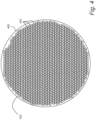
- the pattern may usefully form a single layer of the particles on the deformable layer 110, e.g., as illustrated in Fig. 1 .
- the particles may have a Shore A hardness greater than 40, or more generally, greater than a corresponding hardness of the elastomer of the substrate 102.
- the elastomer of the substrate 102 may have a Shore A hardness at least 10 less than the Shore A hardness of the particles.
- the Shore A hardness of the deformable layer 110 may be less than the Shore A hardness of the particles 122, and may be greater than or equal to the Shore A hardness of the substrate 102.
- the elastic modulus or similar measures describe a bulk property of materials, and may be useful in some instances for distinguishing relatively pliable materials used for the substrate 102 or the deformable layer 110 from relatively rigid materials of the particles 122 disposed on the deformable layer 110.
- hardness as measured may vary according to location within an object.
- the Shore A hardness of the substrate 102 may be usefully measured at a surface of the substrate 102 without the deformable layer 110 applied thereto, and may be measured at a center of the first surface 104 of the substrate 102 or at any other suitable location.
- the Shore A hardness of the various materials or components of the retrographic sensor 100 may be measured in any manner that provides a useful signal for ensuring that the relative hardness of the substrate 102, the deformable layer 110, and the particles 122 cooperate to permit deformation of the retrographic sensor 100 to a target surface while retaining the advantageous properties of the contact surface 120 described herein.
- the imaging system 150 may be coupled to the second surface 106 of the substrate 102, e.g., through the backing 108 and any other hardware for securing the imaging system 150 in a position to capture images reflected from the deformable layer 110 through the substrate 102.
- the imaging system 150 may include one or more cameras 152 using, e.g., optical sensors such as charge-coupled devices, complementary metal-oxide semiconductor image sensors, N-type metal-oxide semiconductor image sensors, or the like, along with any suitable lenses and other optical elements to focus incident light toward these sensors to facilitated image capture.
- the one or more cameras 152 may be configured to capture a plurality of images of the deformable layer 110 through the first elastomer of the substrate 102 in order to obtain images of incident light.
- a camera 152 may use pixel-by-pixel color filters, or other controllable filters or the like to selectively image incident light of a particular wavelength or band of wavelengths.
- An illumination system 160 including one or more light sources 162 such as light-emitting diodes may also be included.
- the illumination system 160 may, for example, be configured to illuminate the deformable layer 110 through the elastomer of the substrate 102, e.g., with a grazing illumination or any other directional illumination that facilitates detection of changes in a surface normal of the deformable layer 110.
- the illumination system may provide illumination with two or more light sources 162, each of the light sources 162 illuminating with a different wavelength band from a different direction.
- this type of illumination may be used to illuminate the deformable layer 110 from different directions at different wavelengths, and capture separate images each illuminated from a different directions simultaneously.
- three light sources 162 in red, green, and blue wavelength bands may be used with a color camera having similarly filtered imaging channels to simultaneously image a surface with illumination from three different directions.
- a controller 170 such as a microprocessor, microcontroller, or other programmable or dedicated circuitry (or combination of the foregoing) may be used to coordinate operation of the imaging system 150 and the illumination system 160 to capture images of the illuminated deformable layer 110, and to process the resulting images to reconstruct the topography of the underlying target surface, for example by evaluating surface normals based on the intensity of illumination received at the cameras 152, and using surface normals to reconstruct surface topography.
- Fig. 2 shows a retrographic sensor positioned for use.
- the retrographic sensor 200 which may be any of the retrographic sensors described herein, may be positioned for use above a target surface 202 from which a topographical image or other quantitative or qualitative image is desired.
- Fig. 3 shows a retrographic sensor applied to a target surface.
- the retrographic sensor 300 which may be any of the retrographic sensors described herein, is positioned for imaging by lowering onto a target surface 302, as illustrated generally by an arrow 304, a contact surface 320 of the retrographic sensor 300, such as any of the contact surfaces described herein, may deform and conform to the target surface 302.
- the contact surface 320 may be configured, e.g., through material selections or the introduction of particles as described herein, to present a relatively low coefficient of friction so that the contact surface 320 can slide over the target surface 302 and more readily conform to the target surface 302 without artifacts introduced by gripping and elastic strain where the contact surface 320 meets the target surface 302.
- the contact surface 320 may be configured as described herein to provide air channels for the egress of air or other gasses or fluids as the contact surface 320 surrounds and moves into topographically varied regions of the target surface 302 such as a recess 322 that might otherwise trap gas in a manner that interferes with accurate surface measurements using the retrographic sensor 300.
- the contract surface 320 of the retrographic sensor 300 is geometrically altered in response to contact with the target surface 302, the geometric alterations cause localized changes in the surface normal and associated localized changes in the amount of light reflected from the deformable layer (not shown) toward imaging devices such as the cameras 152 described above with reference to Fig. 1 .
- This image data may be analyzed to reconstruct the three-dimensional shape of the target surface 302 contacting the deformable layer 110, or the image data may otherwise be processed to extract and/or present two-dimensional or three-dimensional data.
- a variety of suitable configurations and imaging techniques are possible using the retrographic sensors and associated hardware described herein. For example, referring to Fig.
- any other pattern of closely spaced particles 402, e.g., irregular patterns, may also or instead be used, provided that the particles 402 are sufficiently close to one another to rigidly maintain physical channels therebetween for egress of gas when the contact surface 420 is pressed against a target surface. That is, the pattern of particles 402 may advantageously form interstitial channels that permit a flow of air between the particles 402 on a side opposing the deformable layer of the retrographic sensor 400, e.g., on the contact surface 420, in order to avoid trapped pockets of air or other gas that might otherwise interfere with accurate imaging of a target surface.
- a low coefficient of variation (e.g., 0% for perfectly monodisperse particles) serves as a figure of merit that relates particles size distributions to the performance of retrographic sensors.
- a coefficient of variation that is near 0% is preferable.
- coefficients of variation between 15-25% also yield acceptable results, with differentiable imaging performance within that (15-25%) range.
- the particles 402 may be formed of a variety of materials including polymers, natural polymers, and minerals.
- the particles 402 may usefully be formed of, or include, polymethylsilsesquioxane.
- Polymethylsilsesquioxane (PMSQ) provides certain advantages when used as particles 402 in the contact surface 420.
- PMSQ has a relatively low coefficient of friction, it is rigid (relative to an elastomer substrate), and microspheres of PMSQ are readily commercially available in narrow size distributions.
- non-spherical particles may also or instead be used, and the particles 402 may usefully be formed of other types of materials.
- the particles 402 may be formed of a silica, a glass, a melamine, a polystyrene, a polymethylmethacrylate, a polybutylmethacrylate, a styrene/acrylate copolymer, a cellulose, and a polylactic acid.
- the particles 402 may also or instead be formed of a nylon or a polytetrafluoroethylene. More generally, any rigid material that is available in suitable sizes and shapes may be used as particles 402 in a contact surface 420 as contemplated herein.
- microparticles include but are not limited to microspheres formed of methyl methacrylate crosspolymer, polybutyl acrylate and silica, lauryl methacrylate/glycol dimethacrylate crosspolymer and acrylates/ethylhexyl acrylate/dimethicone methacrylate copolymer, HDI/trimethylol hexyllactone crosspolymer and silica, HDI/trimethylol hexyllactone crosspolymer and silica, ethylene/ acrylic acid copolymer, polyethylene, nylon-6, nylon-12, calcium silicate, vinyl dimethicone / methicone silsesquioxane crosspolymer, and combinations of the foregoing.
- Fig. 5 shows a side view of a retrographic sensor.
- the retrographic sensor 500 may be any of the retrographic sensors described herein, except as otherwise noted. While the particles 522 of the retrographic sensor 500 may be at least partially embedded in a deformable layer 510, e.g., as described above, the particles 522 may also or instead be secured to the deformable layer 510 by an adhesive 580 such as a polyurethane, or otherwise indirectly coupled to the deformable layer 510 through one or more intermediate layers.
- an adhesive 580 such as a polyurethane
- the particles 522 may extend out of the adhesive 580 in order to benefit from any associated, low coefficient of friction, as well as the resulting interstitial channels, although the amount of the particles 522 extending beyond the adhesive 580 may depend on a number of factors such as the strength of the adhesive 580 and the shape of the particles 522.
- the particles 522 may be spherical particles, and may extend by at least one half of their diameter above the layer of adhesive 580 joining the particles 522 to the deformable layer 510.
- Fig. 6 shows a side view of a retrographic sensor.
- the retrographic sensor 600 may be any of the retrographic sensors described herein, except as otherwise noted. While the particles described herein can provide one possible contact surface, the retrographic sensor 600 may more generally include a contact surface 620 disposed on a deformable layer 610 having non-planar features 622 forming interstitial channels 690 that permit a flow of air between the non-planar features 622.
- non-planar features 622 may usefully have a hardness greater than the substrate 602 in order to consistently transfer the topography of a target surface into the deformable layer 610 and substrate 602 upon contact, as well as a coefficient of friction less than the deformable layer 610 in order to facilitate movement of the contact surface 620 along a target surface when the retrographic sensor 600 is positioned for use on the target surface.
- the non-planar features 622 may include particles disposed on the deformable layer 610 as described herein.
- the non-planar features 622 may also or instead include pillars extending from the deformable layer 610.
- the hardness of the non-planar features 622 may be greater than the deformable layer 610.
- the non-planar features 622 may generally extend normal to the surface of the substrate 602, e.g., with vertical walls, or the non-planar features 622 may be curved, angled, or otherwise variably shaped along an axis parallel to the substrate normal.
- the non-planar features 622 may also or instead be formed in the deformable layer 610.
- an array of protrusions can be molded directly into the deformable layer 610, e.g., by constructing a mold of an array of small depressions and filling the depressions with a material that cures to provide a relatively hard surface with a relatively low coefficient of friction. These filled depressions can then be transferred and attached to a sensor surface, at which point they form an array of non-planar features 622 providing similar advantages to the particles described herein.
- Fig. 7 shows a side view of a retrographic sensor.
- the retrographic sensor 700 may be any of the retrographic sensors described herein, except as otherwise noted.
- the retrographic sensor 700 may include a number of non-planar features 722 for improved imaging as described herein.
- the non-planar features 722 may include tapered structures extending from the deformable layer.
- the tapered structures may, for example, include pyramids, cones, truncated cones, or any other tapered structures or the like.
- High aspect structures may impose artifacts based on the shear forces on the contact surface 720 of the retrographic sensor 700, and are preferably avoided unless the detection of such forces is intended or helpful for a particular imaging application.
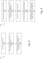
- Fig. 8 shows a flowchart of a method for fabricating a retrographic sensor.
- the method 800 may include forming a contact surface such as any of the contact surfaces described herein on the deformable layer.
- the contact surface may be configured to contact a target surface for imaging with a retrographic sensor.
- the contact surface may include particles harder than the substrate and disposed in a pattern on the deformable layer and separated from the substrate by deformable layer.
- this may include applying a powder of six micron, monodisperse microspheres of polymethylsilsesquioxane to the deformable layer in a manner that distributes the powder into a closely packed monolayer.
- Forming the contact surface may also or instead include applying an aqueous polyurethane suspension or other adhesive to the surface, and allowing the adhesive to spread and wet the deformable layer and the microspheres.
- spin coating may be used to apply the aqueous polyurethane to the deformable layer, subject to suitable coordination of spin coater rotational velocity and viscosity of the suspension (or concentration of microspheres in the concentration, or any other proxy for viscosity or flow).
- forming the contact surface may include applying the particles onto the deformable layer in an aqueous solution of polyurethane. In another aspect, this may include spin coating a mixture of an adhesive and particles such as monodisperse particles of polymethylsilsesquioxane onto the deformable layer. In any case, forming the contact surface may also include drying the adhesive to provide an array of particles with exposed top surfaces and bottom portions adhered to the thermoplastic elastomer material of the deformable layer.
- the method 900 may include illuminating the material of the deformable layer with a light source such as a light emitting diode or array of light emitting diodes from a side facing the substrate.
- a light source such as a light emitting diode or array of light emitting diodes
- the method 900 may include contacting the contact surface of the retrographic sensor to a target surface to geometrically alter the deformable layer.
- the method 900 may include capturing an image of the deformable layer from the side facing the substrate while illuminating the material and contacting the contact surface to the target surface. This may also or instead include capturing a number of images to provide side illumination for different angles, which may increase accuracy, provide additional information about occluded surface, and otherwise improve the quantitative accuracy of reconstructed three-dimensional images resulting therefrom.
- the method 900 may include processing images to recover target surface information such as surface topography or other two-dimensional or three-dimensional information.
- this includes analyzing an image (or a plurality of images) to determine a three-dimensional geometry of the target surface, for example by inferring surface normals from the intensity of reflected light, and integrating surface normals to determine a height of the target surface at locations within the image.
- This may also or instead include analyzing a plurality of images obtained, e.g., with different angles or directions of grazing illumination.
- the method 900 may include illuminating the deformable layer from two or more different directions, capturing the image of the deformable layer while illuminated from each of the two or more different directions, and analyzing a resulting plurality of images to determine the three-dimensional geometry of the target surface.
- the imaging system may be channelized using color, e.g., to support simultaneous imaging of illumination from different directions.
- the method 900 may include illuminating the deformable layer simultaneously with a first light source of a first color and a second light source of a second color different from the first color.
- the method 900 may further include capturing a multi-color image of the deformable layer, distinguishing between a pattern of illumination from the first light source and the second light source, and analyzing the multi-color image to determine the three-dimensional geometry of the target surface based on the pattern of illumination from the first light source and the second light source.
- three different colors such as red, green, and blue may be readily discriminated by commercially available optical systems such as color cameras or color image sensors, and may be used to channelize the imaging system to support simultaneous imaging of illumination from three different directions at the same time, e.g., in a single color image.
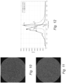
- Fig. 10 shows an optical microscope image of an array of 6 micron microspheres of a first type
- Fig. 11 shows an optical microscope image of an array of 6 micron microspheres of a second type.
- the microspheres of Fig. 11 (Type A) are known to be more monodisperse, e.g., with a more consistent diameter, than those of Fig. 10 (Type B) and are thus expected to create a more regular pattern when packing into a two-dimensional array, e.g., when applied as a monolayer to a contact surface of a retrographic sensor.
- Fig 12 shows an average radial power spectrum for the microsphere arrays of Figs. 10 and 11 . While a number of techniques may be used to measure regularity of geometric structures, the power spectrum of the imaged surfaces presents a useful metric for evaluating the suitability of a particle pattern for high-resolution, error-free imaging. In order to derive this quantity, optical microscope images of the contact surface may be bandpassed and thresholded to enhance contrast, yielding images such as those depicted in Figs. 10-11 . The bandpassed, thresholded images (such as those in Figs.
- the frequency domain representation 10-11 may then be multiplied by a Gaussian window to minimize edge artifacts (from the black border of the images), resulting in a convolution of the frequency domain representation of the images with a Gaussian window.
- the magnitudes of the frequency domain representation may then be squared to obtain a two-dimensional power spectrum.
- the power spectrum of a less regular pattern of particles is expected to have a lower frequency and a wider band of strong frequencies than the more regular pattern.
- the two-dimensional power spectrum will have radial symmetry, so the signals can be radially averaged, and the DC and other very low frequency components can be discarded.
- the resulting power spectra for the patterns in Fig. 10 (Type A) and Fig. 11 (Type B) are illustrated in Fig. 12 .
- a peak power v p may be located at a peak frequency f p .
- the half power frequencies f a and f b are then defined as the frequencies above and below the peak frequency f p where the power is 50% of the peak power v p .
- These values are labelled in Fig. 12 for the particles of Type B.
- This Q score serves as a figure of merit for regularity, with a higher score indicating a more regular array of particles on the contact surface.
- the particles of Type B have a Q score of about 4.7, and are very good for imaging.
- the particles of Type A have a Q score of about 3.9 and are also suitable for imaging.
- a Q score above 2 for microspheres of 1-20 microns indicates a pattern that is sufficiently regular for use in a retrographic sensor without introducing significant imaging artifacts that impede accuracy or resolution.
- the contact surface of a retrographic sensor may usefully have a pattern of microspheres with a radially averaged two-dimensional power spectrum having a Q score of at least 2, where the Q score is equal to the peak frequency divided by the difference of the half power frequencies (of the radially averaged two-dimensional power spectrum).
- a Q score above 3 generally yields noticeably improved performance, and a Q score above 4.5 appears to yield the best possible imaging through a monolayer of particles.
- the Q score of 4.5 further suggests highly regular packing consistent with microspheres of relatively uniform size and shape (e.g., monodisperse).
- highly monodisperse particles may also yield a poor Q score under certain circumstances, such as where the particles are unevenly distributed, or where the particles only partially cover a surface leaving relatively large, open areas. In such cases, the contact surface may produce a low Q score (possibly an unusably low Q score) despite a high geometric regularity of the individual particles.
- the above systems, devices, methods, processes, and the like may be realized in hardware, software, or any combination of these suitable for a particular application.
- the hardware may include a general-purpose computer and/or dedicated computing device. This includes realization in one or more microprocessors, microcontrollers, embedded microcontrollers, programmable digital signal processors or other programmable devices or processing circuitry, along with internal and/or external memory. This may also, or instead, include one or more application specific integrated circuits, programmable gate arrays, programmable array logic components, or any other device or devices that may be configured to process electronic signals.
- a realization of the processes or devices described above may include computer-executable code created using a structured programming language such as C, an object oriented programming language such as C++, or any other high-level or low-level programming language (including assembly languages, hardware description languages, and database programming languages and technologies) that may be stored, compiled or interpreted to run on one of the above devices, as well as heterogeneous combinations of processors, processor architectures, or combinations of different hardware and software.
- the methods may be embodied in systems that perform the steps thereof, and may be distributed across devices in a number of ways. At the same time, processing may be distributed across devices such as the various systems described above, or all of the functionality may be integrated into a dedicated, standalone device or other hardware.
- means for performing the steps associated with the processes described above may include any of the hardware and/or software described above. All such permutations and combinations are intended to fall within the scope of the present disclosure.
- Embodiments disclosed herein may include computer program products comprising computer-executable code or computer-usable code that, when executing on one or more computing devices, performs any and/or all of the steps thereof.
- the code may be stored in a non-transitory fashion in a computer memory, which may be a memory from which the program executes (such as random-access memory associated with a processor), or a storage device such as a disk drive, flash memory or any other optical, electromagnetic, magnetic, infrared or other device or combination of devices.
- any of the systems and methods described above may be embodied in any suitable transmission or propagation medium carrying computer-executable code and/or any inputs or outputs from same.
- performing the step of X includes any suitable method for causing another party such as a remote user, a remote processing resource (e.g., a server or cloud computer) or a machine to perform the step of X.
- performing steps X, Y and Z may include any method of directing or controlling any combination of such other individuals or resources to perform steps X, Y and Z to obtain the benefit of such steps.
Landscapes
- Physics & Mathematics (AREA)
- General Physics & Mathematics (AREA)
- Length Measuring Devices By Optical Means (AREA)
- Investigating Or Analysing Materials By Optical Means (AREA)
- Optical Elements Other Than Lenses (AREA)
Applications Claiming Priority (3)
| Application Number | Priority Date | Filing Date | Title |
|---|---|---|---|
| US201862727816P | 2018-09-06 | 2018-09-06 | |
| EP19857644.9A EP3847438B1 (de) | 2018-09-06 | 2019-09-06 | Retrografische sensoren |
| PCT/US2019/049962 WO2020051458A1 (en) | 2018-09-06 | 2019-09-06 | Retrographic sensors |
Related Parent Applications (1)
| Application Number | Title | Priority Date | Filing Date |
|---|---|---|---|
| EP19857644.9A Division EP3847438B1 (de) | 2018-09-06 | 2019-09-06 | Retrografische sensoren |
Publications (3)
| Publication Number | Publication Date |
|---|---|
| EP4477993A2 true EP4477993A2 (de) | 2024-12-18 |
| EP4477993A3 EP4477993A3 (de) | 2025-02-26 |
| EP4477993B1 EP4477993B1 (de) | 2026-08-12 |
Family
ID=69723279
Family Applications (2)
| Application Number | Title | Priority Date | Filing Date |
|---|---|---|---|
| EP24210345.5A Active EP4477993B1 (de) | 2018-09-06 | 2019-09-06 | Retrographische sensoren |
| EP19857644.9A Active EP3847438B1 (de) | 2018-09-06 | 2019-09-06 | Retrografische sensoren |
Family Applications After (1)
| Application Number | Title | Priority Date | Filing Date |
|---|---|---|---|
| EP19857644.9A Active EP3847438B1 (de) | 2018-09-06 | 2019-09-06 | Retrografische sensoren |
Country Status (7)
| Country | Link |
|---|---|
| US (2) | US11846499B2 (de) |
| EP (2) | EP4477993B1 (de) |
| JP (1) | JP7502274B2 (de) |
| CN (1) | CN113227762A (de) |
| CA (1) | CA3111989A1 (de) |
| SG (1) | SG11202102280SA (de) |
| WO (1) | WO2020051458A1 (de) |
Families Citing this family (10)
| Publication number | Priority date | Publication date | Assignee | Title |
|---|---|---|---|---|
| EP4477993B1 (de) | 2018-09-06 | 2026-08-12 | Gelsight, Inc. | Retrographische sensoren |
| WO2021076697A1 (en) * | 2019-10-15 | 2021-04-22 | Massachusetts Institute Of Technology | Retrographic sensors with compact illumination |
| WO2022132300A2 (en) * | 2020-12-15 | 2022-06-23 | Massachusetts Institute Of Technology | Retrographic sensors with fluorescent illumination |
| WO2022191910A1 (en) * | 2021-03-08 | 2022-09-15 | Massachusetts Institute Of Technology | Enhanced depth estimation using deep learning |
| USD989637S1 (en) * | 2021-06-16 | 2023-06-20 | Gelsight, Inc. | Retrographic sensor cartridge |
| US11709113B2 (en) * | 2021-07-08 | 2023-07-25 | Textron Innovations Inc. | Elastomeric bearing monitoring system |
| EP4359208A1 (de) * | 2021-08-02 | 2024-05-01 | Gelsight, Inc. | Abriebfester verbundstoff |
| JP2026505287A (ja) * | 2023-01-30 | 2026-02-13 | ジェルサイト, インコーポレイテッド | 触覚知能のためのシステムおよび方法 |
| US20240318954A1 (en) * | 2023-03-24 | 2024-09-26 | Gelsight, Inc. | Systems and methods for tactile intelligence |
| CN121488281A (zh) * | 2023-04-24 | 2026-02-06 | 胶视公司 | 使用照射叠加的运动补偿 |
Family Cites Families (21)
| Publication number | Priority date | Publication date | Assignee | Title |
|---|---|---|---|---|
| ATE35794T1 (de) * | 1983-04-04 | 1988-08-15 | Siemens Ag | Druckabbildungssystem. |
| WO1989002722A1 (en) * | 1987-09-24 | 1989-04-06 | Siemens Aktiengesellschaft | Fingerprint sensing device |
| US5459329A (en) * | 1994-09-14 | 1995-10-17 | Georgia Tech Research Corporation | Video based 3D tactile reconstruction input device having a deformable membrane |
| US5798181A (en) * | 1994-10-04 | 1998-08-25 | W. L. Gore & Associates, Inc. | Fluoropolymer coated elastomeric rollers and structures |
| CN1264003C (zh) * | 2000-08-31 | 2006-07-12 | 株式会社东京大学Tlo | 光学式触觉传感器 |
| US20020102389A1 (en) * | 2000-12-01 | 2002-08-01 | Nielsen Steven M. | Retroreflective laminate comprising a tear resistant film |
| JP4475186B2 (ja) * | 2005-06-30 | 2010-06-09 | 富士ゼロックス株式会社 | 情報記録媒体の製造方法 |
| EP2294375B8 (de) * | 2008-06-19 | 2024-02-14 | Massachusetts Institute of Technology | Tastsensor, der elastomerische bildgebung verwendet |
| JP5504430B2 (ja) | 2008-09-17 | 2014-05-28 | アルケア株式会社 | サポート用被服 |
| CN102096315B (zh) * | 2010-12-22 | 2012-04-04 | 青岛理工大学 | 整片晶圆纳米压印的装置和方法 |
| US8823639B2 (en) * | 2011-05-27 | 2014-09-02 | Disney Enterprises, Inc. | Elastomeric input device |
| US9127938B2 (en) * | 2011-07-28 | 2015-09-08 | Massachusetts Institute Of Technology | High-resolution surface measurement systems and methods |
| US8971593B2 (en) * | 2011-10-12 | 2015-03-03 | Lumidigm, Inc. | Methods and systems for performing biometric functions |
| EP2910009A4 (de) * | 2012-10-17 | 2016-07-27 | Gelsight Inc | Dreidimensionale digitale bedruckung und visualisierung von objekten |
| CN105392722B (zh) * | 2013-03-08 | 2017-06-09 | 胶视公司 | 基于接触的连续三维测量 |
| US10094960B2 (en) * | 2013-08-19 | 2018-10-09 | 3M Innovative Properties Company | Retroreflective sheeting including a low elastic modulus layer |
| US9998729B2 (en) * | 2014-12-12 | 2018-06-12 | Ryan Lilien | Method and system for three dimensional imaging and analysis |
| EP3593529B1 (de) * | 2017-03-06 | 2022-07-06 | Gelsight, Inc. | Oberflächentopographiemesssysteme |
| EP4477993B1 (de) | 2018-09-06 | 2026-08-12 | Gelsight, Inc. | Retrographische sensoren |
| WO2022191910A1 (en) * | 2021-03-08 | 2022-09-15 | Massachusetts Institute Of Technology | Enhanced depth estimation using deep learning |
| US12280495B2 (en) * | 2021-09-07 | 2025-04-22 | Khalifa University of Science and Technology | Robotic manipulator with camera and tactile sensing |
-
2019
- 2019-09-06 EP EP24210345.5A patent/EP4477993B1/de active Active
- 2019-09-06 CN CN201980072883.8A patent/CN113227762A/zh active Pending
- 2019-09-06 SG SG11202102280SA patent/SG11202102280SA/en unknown
- 2019-09-06 EP EP19857644.9A patent/EP3847438B1/de active Active
- 2019-09-06 WO PCT/US2019/049962 patent/WO2020051458A1/en not_active Ceased
- 2019-09-06 CA CA3111989A patent/CA3111989A1/en active Pending
- 2019-09-06 JP JP2021512669A patent/JP7502274B2/ja active Active
-
2021
- 2021-03-05 US US17/193,175 patent/US11846499B2/en active Active
-
2023
- 2023-12-18 US US18/542,988 patent/US20240384983A1/en active Pending
Also Published As
| Publication number | Publication date |
|---|---|
| US20210215474A1 (en) | 2021-07-15 |
| US11846499B2 (en) | 2023-12-19 |
| EP3847438A1 (de) | 2021-07-14 |
| JP7502274B2 (ja) | 2024-06-18 |
| JP2021536579A (ja) | 2021-12-27 |
| WO2020051458A1 (en) | 2020-03-12 |
| SG11202102280SA (en) | 2021-04-29 |
| EP3847438A4 (de) | 2022-05-18 |
| CN113227762A (zh) | 2021-08-06 |
| EP4477993B1 (de) | 2026-08-12 |
| EP3847438B1 (de) | 2024-11-06 |
| US20240384983A1 (en) | 2024-11-21 |
| CA3111989A1 (en) | 2020-03-12 |
| EP4477993A3 (de) | 2025-02-26 |
Similar Documents
| Publication | Publication Date | Title |
|---|---|---|
| US11846499B2 (en) | Retrographic sensors | |
| US20220299422A1 (en) | Image-Based Assay Performance Improvement | |
| CN1571920A (zh) | 光学式触觉传感器 | |
| JP2021535395A (ja) | アッセイ精度向上 | |
| KR20140041890A (ko) | 고해상도 표면 측정 시스템 및 방법 | |
| JP5736453B2 (ja) | 粒子撮像デバイスにおける測定精度を上げるための装置、システムおよび方法 | |
| CN101040184A (zh) | 用于尺寸、外形和棱角性分析以及用于矿石和岩石颗粒的成分分析的设备和方法 | |
| WO2020055543A1 (en) | Image-based assay using intelligent monitoring structures | |
| HK40119406A (en) | Retrographic sensors | |
| JP5873183B2 (ja) | 画像データ処理方法及びシステム | |
| HK40058399A (en) | Retrographic sensors | |
| JP2004245695A (ja) | 画像処理方法と異物検出装置 | |
| US20260051071A1 (en) | Motion compensation using illumination superposition | |
| RU2782368C2 (ru) | Ретрографические датчики | |
| Sharp et al. | Optical measurement of contact forces using frustrated total internal reflection | |
| NL2038735B1 (en) | Tactile sensor | |
| CN118298471A (zh) | 感测膜及其制造方法、传感器及其测量方法、机器人 | |
| CA3234459A1 (en) | Retrographic sensing | |
| JP2010257434A (ja) | マウスパッドの製造方法 | |
| WO2005075961A1 (ja) | 光輝感評価方法および光輝感評価装置 | |
| Moghaddam | Estimation of stripping by static immersion test using image processing and machine learning | |
| Kilcik et al. | A New Approximation for Central and Peripheral Umbral Dots Separation | |
| Davis et al. | Benchmarking Resilience and Sensitivity of Polyurethane-Based Vision-Based Tactile Sensors | |
| WO2023228527A1 (ja) | 光学式触覚センサ及びセンサシステム | |
| Bautista et al. | Preliminary Evaluation of Mechanoluminescent Lattice-Patterned Sensing Skin for Visuotactile Contact Differentiation |
Legal Events
| Date | Code | Title | Description |
|---|---|---|---|
| PUAI | Public reference made under article 153(3) epc to a published international application that has entered the european phase |
Free format text: ORIGINAL CODE: 0009012 |
|
| STAA | Information on the status of an ep patent application or granted ep patent |
Free format text: STATUS: THE APPLICATION HAS BEEN PUBLISHED |
|
| AC | Divisional application: reference to earlier application |
Ref document number: 3847438 Country of ref document: EP Kind code of ref document: P |
|
| AK | Designated contracting states |
Kind code of ref document: A2 Designated state(s): AL AT BE BG CH CY CZ DE DK EE ES FI FR GB GR HR HU IE IS IT LI LT LU LV MC MK MT NL NO PL PT RO RS SE SI SK SM TR |
|
| REG | Reference to a national code |
Ref country code: DE Ref legal event code: R079 Ref country code: DE Ref legal event code: R079 Ref document number: 602019087501 Country of ref document: DE Free format text: PREVIOUS MAIN CLASS: G01B0011240000 Ipc: G01B0001000000 |
|
| PUAL | Search report despatched |
Free format text: ORIGINAL CODE: 0009013 |
|
| AK | Designated contracting states |
Kind code of ref document: A3 Designated state(s): AL AT BE BG CH CY CZ DE DK EE ES FI FR GB GR HR HU IE IS IT LI LT LU LV MC MK MT NL NO PL PT RO RS SE SI SK SM TR |
|
| RIC1 | Information provided on ipc code assigned before grant |
Ipc: G01B 11/24 20060101ALI20250117BHEP Ipc: G01B 11/30 20060101ALI20250117BHEP Ipc: G01B 1/00 20060101AFI20250117BHEP |
|
| REG | Reference to a national code |
Ref country code: HK Ref legal event code: DE Ref document number: 40119406 Country of ref document: HK |
|
| STAA | Information on the status of an ep patent application or granted ep patent |
Free format text: STATUS: REQUEST FOR EXAMINATION WAS MADE |
|
| 17P | Request for examination filed |
Effective date: 20250826 |
|
| RIN1 | Information on inventor provided before grant (corrected) |
Inventor name: ADELSON, EDWARD, H. Inventor name: COTTRELL, F. RICHARD |
|
| GRAP | Despatch of communication of intention to grant a patent |
Free format text: ORIGINAL CODE: EPIDOSNIGR1 |
|
| STAA | Information on the status of an ep patent application or granted ep patent |
Free format text: STATUS: GRANT OF PATENT IS INTENDED |
|
| INTG | Intention to grant announced |
Effective date: 20260304 |
|
| GRAS | Grant fee paid |
Free format text: ORIGINAL CODE: EPIDOSNIGR3 |
|
| GRAA | (expected) grant |
Free format text: ORIGINAL CODE: 0009210 |
|
| STAA | Information on the status of an ep patent application or granted ep patent |
Free format text: STATUS: THE PATENT HAS BEEN GRANTED |
|
| AC | Divisional application: reference to earlier application |
Ref document number: 3847438 Country of ref document: EP Kind code of ref document: P |
|
| AK | Designated contracting states |
Kind code of ref document: B1 Designated state(s): AL AT BE BG CH CY CZ DE DK EE ES FI FR GB GR HR HU IE IS IT LI LT LU LV MC MK MT NL NO PL PT RO RS SE SI SK SM TR |
|
| REG | Reference to a national code |
Ref country code: CH Ref legal event code: F10 Free format text: ST27 STATUS EVENT CODE: U-0-0-F10-F00 (AS PROVIDED BY THE NATIONAL OFFICE) Effective date: 20260812 Ref country code: GB Ref legal event code: FG4D |