EP4477973A1 - Wärmepumpensystem und steuerungsverfahren dafür - Google Patents
Wärmepumpensystem und steuerungsverfahren dafür Download PDFInfo
- Publication number
- EP4477973A1 EP4477973A1 EP23770972.0A EP23770972A EP4477973A1 EP 4477973 A1 EP4477973 A1 EP 4477973A1 EP 23770972 A EP23770972 A EP 23770972A EP 4477973 A1 EP4477973 A1 EP 4477973A1
- Authority
- EP
- European Patent Office
- Prior art keywords
- temperature
- refrigerant
- pressure
- water
- expansion valve
- Prior art date
- Legal status (The legal status is an assumption and is not a legal conclusion. Google has not performed a legal analysis and makes no representation as to the accuracy of the status listed.)
- Pending
Links
Images


Classifications
-
- F—MECHANICAL ENGINEERING; LIGHTING; HEATING; WEAPONS; BLASTING
- F24—HEATING; RANGES; VENTILATING
- F24H—FLUID HEATERS, e.g. WATER OR AIR HEATERS, HAVING HEAT-GENERATING MEANS, e.g. HEAT PUMPS, IN GENERAL
- F24H15/00—Control of fluid heaters
- F24H15/10—Control of fluid heaters characterised by the purpose of the control
- F24H15/174—Supplying heated water with desired temperature or desired range of temperature
-
- F—MECHANICAL ENGINEERING; LIGHTING; HEATING; WEAPONS; BLASTING
- F25—REFRIGERATION OR COOLING; COMBINED HEATING AND REFRIGERATION SYSTEMS; HEAT PUMP SYSTEMS; MANUFACTURE OR STORAGE OF ICE; LIQUEFACTION SOLIDIFICATION OF GASES
- F25B—REFRIGERATION MACHINES, PLANTS OR SYSTEMS; COMBINED HEATING AND REFRIGERATION SYSTEMS; HEAT PUMP SYSTEMS
- F25B41/00—Fluid-circulation arrangements
- F25B41/30—Expansion means; Dispositions thereof
- F25B41/31—Expansion valves
-
- F—MECHANICAL ENGINEERING; LIGHTING; HEATING; WEAPONS; BLASTING
- F24—HEATING; RANGES; VENTILATING
- F24H—FLUID HEATERS, e.g. WATER OR AIR HEATERS, HAVING HEAT-GENERATING MEANS, e.g. HEAT PUMPS, IN GENERAL
- F24H15/00—Control of fluid heaters
- F24H15/20—Control of fluid heaters characterised by control inputs
- F24H15/212—Temperature of the water
- F24H15/215—Temperature of the water before heating
-
- F—MECHANICAL ENGINEERING; LIGHTING; HEATING; WEAPONS; BLASTING
- F24—HEATING; RANGES; VENTILATING
- F24H—FLUID HEATERS, e.g. WATER OR AIR HEATERS, HAVING HEAT-GENERATING MEANS, e.g. HEAT PUMPS, IN GENERAL
- F24H15/00—Control of fluid heaters
- F24H15/20—Control of fluid heaters characterised by control inputs
- F24H15/212—Temperature of the water
- F24H15/219—Temperature of the water after heating
-
- F—MECHANICAL ENGINEERING; LIGHTING; HEATING; WEAPONS; BLASTING
- F24—HEATING; RANGES; VENTILATING
- F24H—FLUID HEATERS, e.g. WATER OR AIR HEATERS, HAVING HEAT-GENERATING MEANS, e.g. HEAT PUMPS, IN GENERAL
- F24H15/00—Control of fluid heaters
- F24H15/20—Control of fluid heaters characterised by control inputs
- F24H15/227—Temperature of the refrigerant in heat pump cycles
- F24H15/231—Temperature of the refrigerant in heat pump cycles at the evaporator
-
- F—MECHANICAL ENGINEERING; LIGHTING; HEATING; WEAPONS; BLASTING
- F24—HEATING; RANGES; VENTILATING
- F24H—FLUID HEATERS, e.g. WATER OR AIR HEATERS, HAVING HEAT-GENERATING MEANS, e.g. HEAT PUMPS, IN GENERAL
- F24H15/00—Control of fluid heaters
- F24H15/20—Control of fluid heaters characterised by control inputs
- F24H15/227—Temperature of the refrigerant in heat pump cycles
- F24H15/232—Temperature of the refrigerant in heat pump cycles at the condenser
-
- F—MECHANICAL ENGINEERING; LIGHTING; HEATING; WEAPONS; BLASTING
- F24—HEATING; RANGES; VENTILATING
- F24H—FLUID HEATERS, e.g. WATER OR AIR HEATERS, HAVING HEAT-GENERATING MEANS, e.g. HEAT PUMPS, IN GENERAL
- F24H15/00—Control of fluid heaters
- F24H15/20—Control of fluid heaters characterised by control inputs
- F24H15/242—Pressure
-
- F—MECHANICAL ENGINEERING; LIGHTING; HEATING; WEAPONS; BLASTING
- F24—HEATING; RANGES; VENTILATING
- F24H—FLUID HEATERS, e.g. WATER OR AIR HEATERS, HAVING HEAT-GENERATING MEANS, e.g. HEAT PUMPS, IN GENERAL
- F24H15/00—Control of fluid heaters
- F24H15/20—Control of fluid heaters characterised by control inputs
- F24H15/258—Outdoor temperature
-
- F—MECHANICAL ENGINEERING; LIGHTING; HEATING; WEAPONS; BLASTING
- F24—HEATING; RANGES; VENTILATING
- F24H—FLUID HEATERS, e.g. WATER OR AIR HEATERS, HAVING HEAT-GENERATING MEANS, e.g. HEAT PUMPS, IN GENERAL
- F24H15/00—Control of fluid heaters
- F24H15/30—Control of fluid heaters characterised by control outputs; characterised by the components to be controlled
- F24H15/375—Control of heat pumps
- F24H15/385—Control of expansion valves of heat pumps
-
- F—MECHANICAL ENGINEERING; LIGHTING; HEATING; WEAPONS; BLASTING
- F24—HEATING; RANGES; VENTILATING
- F24H—FLUID HEATERS, e.g. WATER OR AIR HEATERS, HAVING HEAT-GENERATING MEANS, e.g. HEAT PUMPS, IN GENERAL
- F24H15/00—Control of fluid heaters
- F24H15/40—Control of fluid heaters characterised by the type of controllers
- F24H15/414—Control of fluid heaters characterised by the type of controllers using electronic processing, e.g. computer-based
- F24H15/421—Control of fluid heaters characterised by the type of controllers using electronic processing, e.g. computer-based using pre-stored data
-
- F—MECHANICAL ENGINEERING; LIGHTING; HEATING; WEAPONS; BLASTING
- F24—HEATING; RANGES; VENTILATING
- F24H—FLUID HEATERS, e.g. WATER OR AIR HEATERS, HAVING HEAT-GENERATING MEANS, e.g. HEAT PUMPS, IN GENERAL
- F24H4/00—Fluid heaters characterised by the use of heat pumps
- F24H4/02—Water heaters
-
- F—MECHANICAL ENGINEERING; LIGHTING; HEATING; WEAPONS; BLASTING
- F25—REFRIGERATION OR COOLING; COMBINED HEATING AND REFRIGERATION SYSTEMS; HEAT PUMP SYSTEMS; MANUFACTURE OR STORAGE OF ICE; LIQUEFACTION SOLIDIFICATION OF GASES
- F25B—REFRIGERATION MACHINES, PLANTS OR SYSTEMS; COMBINED HEATING AND REFRIGERATION SYSTEMS; HEAT PUMP SYSTEMS
- F25B13/00—Compression machines, plants or systems, with reversible cycle
-
- F—MECHANICAL ENGINEERING; LIGHTING; HEATING; WEAPONS; BLASTING
- F25—REFRIGERATION OR COOLING; COMBINED HEATING AND REFRIGERATION SYSTEMS; HEAT PUMP SYSTEMS; MANUFACTURE OR STORAGE OF ICE; LIQUEFACTION SOLIDIFICATION OF GASES
- F25B—REFRIGERATION MACHINES, PLANTS OR SYSTEMS; COMBINED HEATING AND REFRIGERATION SYSTEMS; HEAT PUMP SYSTEMS
- F25B30/00—Heat pumps
- F25B30/02—Heat pumps of the compression type
-
- F—MECHANICAL ENGINEERING; LIGHTING; HEATING; WEAPONS; BLASTING
- F25—REFRIGERATION OR COOLING; COMBINED HEATING AND REFRIGERATION SYSTEMS; HEAT PUMP SYSTEMS; MANUFACTURE OR STORAGE OF ICE; LIQUEFACTION SOLIDIFICATION OF GASES
- F25B—REFRIGERATION MACHINES, PLANTS OR SYSTEMS; COMBINED HEATING AND REFRIGERATION SYSTEMS; HEAT PUMP SYSTEMS
- F25B43/00—Arrangements for separating or purifying gases or liquids; Arrangements for vaporising the residuum of liquid refrigerant, e.g. by heat
- F25B43/006—Accumulators
-
- F—MECHANICAL ENGINEERING; LIGHTING; HEATING; WEAPONS; BLASTING
- F25—REFRIGERATION OR COOLING; COMBINED HEATING AND REFRIGERATION SYSTEMS; HEAT PUMP SYSTEMS; MANUFACTURE OR STORAGE OF ICE; LIQUEFACTION SOLIDIFICATION OF GASES
- F25B—REFRIGERATION MACHINES, PLANTS OR SYSTEMS; COMBINED HEATING AND REFRIGERATION SYSTEMS; HEAT PUMP SYSTEMS
- F25B49/00—Arrangement or mounting of control or safety devices
- F25B49/02—Arrangement or mounting of control or safety devices for compression type machines, plants or systems
-
- F—MECHANICAL ENGINEERING; LIGHTING; HEATING; WEAPONS; BLASTING
- F24—HEATING; RANGES; VENTILATING
- F24D—DOMESTIC- OR SPACE-HEATING SYSTEMS, e.g. CENTRAL HEATING SYSTEMS; DOMESTIC HOT-WATER SUPPLY SYSTEMS; ELEMENTS OR COMPONENTS THEREFOR
- F24D17/00—Domestic hot-water supply systems
- F24D17/02—Domestic hot-water supply systems using heat pumps
-
- F—MECHANICAL ENGINEERING; LIGHTING; HEATING; WEAPONS; BLASTING
- F25—REFRIGERATION OR COOLING; COMBINED HEATING AND REFRIGERATION SYSTEMS; HEAT PUMP SYSTEMS; MANUFACTURE OR STORAGE OF ICE; LIQUEFACTION SOLIDIFICATION OF GASES
- F25B—REFRIGERATION MACHINES, PLANTS OR SYSTEMS; COMBINED HEATING AND REFRIGERATION SYSTEMS; HEAT PUMP SYSTEMS
- F25B1/00—Compression machines, plants or systems with non-reversible cycle
- F25B1/10—Compression machines, plants or systems with non-reversible cycle with multi-stage compression
-
- F—MECHANICAL ENGINEERING; LIGHTING; HEATING; WEAPONS; BLASTING
- F25—REFRIGERATION OR COOLING; COMBINED HEATING AND REFRIGERATION SYSTEMS; HEAT PUMP SYSTEMS; MANUFACTURE OR STORAGE OF ICE; LIQUEFACTION SOLIDIFICATION OF GASES
- F25B—REFRIGERATION MACHINES, PLANTS OR SYSTEMS; COMBINED HEATING AND REFRIGERATION SYSTEMS; HEAT PUMP SYSTEMS
- F25B2313/00—Compression machines, plants or systems with reversible cycle not otherwise provided for
- F25B2313/003—Indoor unit with water as a heat sink or heat source
-
- F—MECHANICAL ENGINEERING; LIGHTING; HEATING; WEAPONS; BLASTING
- F25—REFRIGERATION OR COOLING; COMBINED HEATING AND REFRIGERATION SYSTEMS; HEAT PUMP SYSTEMS; MANUFACTURE OR STORAGE OF ICE; LIQUEFACTION SOLIDIFICATION OF GASES
- F25B—REFRIGERATION MACHINES, PLANTS OR SYSTEMS; COMBINED HEATING AND REFRIGERATION SYSTEMS; HEAT PUMP SYSTEMS
- F25B2400/00—General features or devices for refrigeration machines, plants or systems, combined heating and refrigeration systems or heat-pump systems, i.e. not limited to a particular subgroup of F25B
- F25B2400/13—Economisers
-
- F—MECHANICAL ENGINEERING; LIGHTING; HEATING; WEAPONS; BLASTING
- F25—REFRIGERATION OR COOLING; COMBINED HEATING AND REFRIGERATION SYSTEMS; HEAT PUMP SYSTEMS; MANUFACTURE OR STORAGE OF ICE; LIQUEFACTION SOLIDIFICATION OF GASES
- F25B—REFRIGERATION MACHINES, PLANTS OR SYSTEMS; COMBINED HEATING AND REFRIGERATION SYSTEMS; HEAT PUMP SYSTEMS
- F25B2500/00—Problems to be solved
- F25B2500/19—Calculation of parameters
-
- F—MECHANICAL ENGINEERING; LIGHTING; HEATING; WEAPONS; BLASTING
- F25—REFRIGERATION OR COOLING; COMBINED HEATING AND REFRIGERATION SYSTEMS; HEAT PUMP SYSTEMS; MANUFACTURE OR STORAGE OF ICE; LIQUEFACTION SOLIDIFICATION OF GASES
- F25B—REFRIGERATION MACHINES, PLANTS OR SYSTEMS; COMBINED HEATING AND REFRIGERATION SYSTEMS; HEAT PUMP SYSTEMS
- F25B2600/00—Control issues
- F25B2600/25—Control of valves
- F25B2600/2513—Expansion valves
-
- F—MECHANICAL ENGINEERING; LIGHTING; HEATING; WEAPONS; BLASTING
- F25—REFRIGERATION OR COOLING; COMBINED HEATING AND REFRIGERATION SYSTEMS; HEAT PUMP SYSTEMS; MANUFACTURE OR STORAGE OF ICE; LIQUEFACTION SOLIDIFICATION OF GASES
- F25B—REFRIGERATION MACHINES, PLANTS OR SYSTEMS; COMBINED HEATING AND REFRIGERATION SYSTEMS; HEAT PUMP SYSTEMS
- F25B2700/00—Sensing or detecting of parameters; Sensors therefor
- F25B2700/19—Pressures
- F25B2700/195—Pressures of the condenser
-
- F—MECHANICAL ENGINEERING; LIGHTING; HEATING; WEAPONS; BLASTING
- F25—REFRIGERATION OR COOLING; COMBINED HEATING AND REFRIGERATION SYSTEMS; HEAT PUMP SYSTEMS; MANUFACTURE OR STORAGE OF ICE; LIQUEFACTION SOLIDIFICATION OF GASES
- F25B—REFRIGERATION MACHINES, PLANTS OR SYSTEMS; COMBINED HEATING AND REFRIGERATION SYSTEMS; HEAT PUMP SYSTEMS
- F25B2700/00—Sensing or detecting of parameters; Sensors therefor
- F25B2700/21—Temperatures
- F25B2700/2106—Temperatures of fresh outdoor air
-
- F—MECHANICAL ENGINEERING; LIGHTING; HEATING; WEAPONS; BLASTING
- F25—REFRIGERATION OR COOLING; COMBINED HEATING AND REFRIGERATION SYSTEMS; HEAT PUMP SYSTEMS; MANUFACTURE OR STORAGE OF ICE; LIQUEFACTION SOLIDIFICATION OF GASES
- F25B—REFRIGERATION MACHINES, PLANTS OR SYSTEMS; COMBINED HEATING AND REFRIGERATION SYSTEMS; HEAT PUMP SYSTEMS
- F25B2700/00—Sensing or detecting of parameters; Sensors therefor
- F25B2700/21—Temperatures
- F25B2700/2116—Temperatures of a condenser
- F25B2700/21161—Temperatures of a condenser of the fluid heated by the condenser
Definitions
- the disclosure relates to a heat pump system and method of controlling the same, and more particularly to a heat pump type system and method of controlling the same, capable of supplying hot water through heat exchange.
- heat pump performs cooling, heating (air to air) and water supply (air to water) by using the heat produced and recovered in a circulation process of compression, condensation and evaporation of a refrigerant.
- a multi-type cooling and heating device (hereinafter, referred to as an air conditioning system) that uses the heat pump method is comprised of an outdoor unit, an indoor unit, a hydro unit and a water tank unit, and uses the heat of the heat pump for indoor floor heating, hot water supply, indoor air cooling or heating, etc.
- a heat pump system of the traditional air conditioner exchanges heat with air through an evaporator of the outdoor unit and controls the temperature of indoor air to meet the demand of the user through a condenser of the indoor unit.
- An eco heating/cooling solution (EHS) system also exchanges heat with air through the outdoor unit, but supplies water of a temperature that meets a user demand by performing heat exchange between a refrigerant and water through a heat exchanger in the indoor unit or the outdoor unit.
- EHS eco heating/cooling solution
- the EHS system is classified into a mono system with both an evaporator and a condenser arranged in the outdoor unit and a split system with an evaporator arranged in the outdoor unit and a condenser arranged inside, and the supplied water is used for floor heating, radiator, hot water supply, a fan coil unit, etc.
- An expansion valve which changes high-pressure refrigerant to low-pressure refrigerant through phase change of the refrigerant, is controlled with an electric expansion valve (EEV), and when there is no pressure sensor in the system, expansion valve control is performed based on the compressor discharge temperature through a temperature sensor, or when there are both the pressure sensor and the temperature sensor, low pressure is measured, temperature at an inlet of a low-pressure compressor is measured, and then low-pressure superheat degree is also controlled.
- EEV electric expansion valve
- an injection compressor is applied through a supercooling heat exchanger in addition to the main components, the evaporator, condenser, compressor and expansion valve, in which case, EEV control is performed to secure a low-pressure superheat degree through a pressure sensor and a temperature sensor.
- the disclosure provides a heat pump system and method of controlling the same, by which expansion valve control is performed based on a target condensation temperature to attain hot water output, increase operation reliability under low/high temperature outdoor conditions and perform a heating operation at an optimal efficiency.
- a heat pump system includes a compressor configured to compress a refrigerant; a high-pressure pressure sensor configured to detect pressure of the compressed refrigerant; a water heat exchanger in which the compressed refrigerant exchanges heat with input water; an expansion valve configured to expand the refrigerant condensed in the water heat exchanger; an outdoor heat exchanger in which the refrigerant expanded in the expansion valve exchanges heat with outdoor air; a supercooling temperature sensor configured to detect a temperature of the refrigerant having passed the water heat exchanger; a water output temperature sensor configured to detect a temperature of water having undergone heat exchange in the water heat exchanger; and a controller configured to determine a target condensation temperature of the refrigerant based on a detection result of the water output temperature sensor, compare the target condensation temperature with a current condensation temperature, which is a value obtained by converting the pressure detected by the high-pressure pressure sensor into a saturation temperature, and control an opening degree of the expansion valve based on a result of the comparing.
- An outdoor temperature sensor configured to detect outdoor temperature may be further included, and the controller may be configured to set an upper limit of the target condensation temperature based on a maximum water output temperature depending on the outdoor temperature detected by the outdoor temperature sensor and a target water output temperature.
- An input water temperature sensor configured to detect input water temperature may be further included, and the controller may be configured to set a lower limit of the target condensation temperature based on the input water temperature detected by the input water temperature sensor and a minimum compression ratio.
- the controller may be configured to control the expansion valve to increase an opening degree of the expansion valve in response to a current condensation temperature based on a detection result of the condensation temperature, which is a value obtained by converting the pressure detected by the high-pressure pressure sensor into a saturation temperature, being higher than the determined target condensation temperature.
- the controller may be configured to control the expansion valve to decrease an opening degree of the expansion valve in response to a current condensation temperature based on a detection result of the condensation temperature, which is a value obtained by converting the pressure detected by the high-pressure pressure sensor into a saturation temperature, being lower than the determined target condensation temperature.
- the controller may be configured to set a value obtained by adding a first constant to a current water output temperature detected by the water output temperature sensor to the target condensation temperature.
- the controller may be configured to set a lower one of a value obtained by adding a second constant to a maximum water output temperature based on the outdoor temperature detected by the outdoor temperature sensor and a value obtained by adding a third constant to the target water output temperature to an upper limit of the target condensation temperature.
- the controller may be configured to set a higher one of a value obtained by adding a fourth constant to the input water temperature detected by the input water temperature sensor and a value obtained by multiplying a value obtained by adding a fifth constant to the minimum compression ratio by a low absolute pressure to a lower limit of the target condensation temperature.
- An accumulator configured to temporarily store the refrigerant and separate a refrigerant in a liquid state not yet evaporated, and the controller may be configured to control the expansion valve not to reduce an opening degree of the expansion valve in response to determining that there is no refrigerant in the accumulator.
- a low-pressure temperature sensor and a low-pressure pressure sensor configured to detect low-pressure temperature and low-pressure pressure of the refrigerant before flowing into the accumulator may be further included, and the controller may be configured to control an opening degree of the expansion valve based on a difference between the low-pressure temperature detected by the low-pressure temperature sensor and a low-pressure saturation temperature based on pressure detected by the low-pressure pressure sensor.
- the controller may be configured to control the expansion valve not to reduce an opening degree of the expansion valve and also control a low-pressure superheat degree in response to the low-pressure temperature determined to be higher than the low-pressure saturation temperature.
- the compressor may include a first compressor with the refrigerant having passed the water heat exchanger flowing thereto and being compressed therein, and a second compressor with both the refrigerant having passed the first compressor and a refrigerant branched and injected from a supercooling heat exchanger located between the water heat exchanger and the expansion valve flowing thereto and being compressed therein.
- the first to fifth constants may be determined based on a deviation between an actual temperature and a detected temperature and an optimal condensation temperature.
- a method of controlling a heat pump system includes detecting pressure of a refrigerant compressed by a compressor and setting a value obtained by converting the pressure into a saturation temperature to a condensation temperature; detecting temperature of water having undergone heat exchange in the water heat exchanger; determining a target condensation temperature of the refrigerant based on the detected temperature of the water having undergone heat exchange; comparing the target condensation temperature with the detected current condensation temperature of a high-pressure pressure sensor; and controlling an opening degree of an expansion valve based on a result of the comparing.
- Detecting outdoor temperature may be further included, and the determining of the target condensation temperature may include setting an upper limit of the target condensation temperature based on a maximum water output temperature based on the detected outdoor temperature and a target water output temperature.
- Detecting input water temperature may be further included, and the determining of the target condensation temperature may include setting a lower limit of the target condensation temperature based on the detected input water temperature and a minimum compression ratio.
- the controlling of the opening degree of the expansion valve may include controlling the expansion valve to increase the opening degree of the expansion valve in response to the detected current condensation temperature of a high-pressure pressure sensor being higher than the determined target condensation temperature.
- the controlling of the opening degree of the expansion valve may include controlling the expansion valve to decrease the opening degree of the expansion valve in response to the detected current condensation temperature of a high-pressure pressure sensor being lower than the determined target condensation temperature.
- the determining of the target condensation temperature may include setting a value obtained by adding a first constant to the detected current water output temperature to the target condensation temperature.
- the setting of the upper limit of the target condensation temperature may include setting a lower one of a value obtained by adding a second constant to a maximum water output temperature based on the detected outdoor temperature and a value obtained by adding a third constant to the target water output temperature to an upper limit of the target condensation temperature.
- the setting of the lower limit of the target condensation temperature may include setting a higher one of a value obtained by adding a fourth constant to the detected input water temperature and a value obtained by multiplying a value obtained by adding a fifth constant to the minimum compression ratio by a low absolute pressure to a lower limit of the target condensation temperature.
- Controlling the expansion valve not to decrease an opening degree of the expansion valve in response to determining that there is no refrigerant in the accumulator may be further included.
- Detecting low-pressure temperature and low-pressure pressure of the refrigerant before flowing into the accumulator may be further included, and the controlling of the expansion valve may include controlling the opening degree of the expansion valve based on a difference between the detected low-pressure temperature and a low-pressure saturation temperature based on the detected pressure.
- the controlling of the opening of the expansion valve may include controlling the expansion valve not to reduce the opening degree of the expansion valve and also controlling a low-pressure superheat degree in response to the low-pressure temperature determined to be higher than the low-pressure saturation temperature.
- Compressing the refrigerant may be further included, and the compressing of the refrigerant may include a first compression process in which the refrigerant having passed the water heat exchanger flows in and is compressed, and a second compression process in which both the refrigerant having passed the first compression process and a refrigerant branched and injected from a supercooling heat exchanger located between the water heat exchanger and the expansion valve flow in and are compressed.
- the first to fifth constants may be determined based on a deviation between an actual temperature and a detected temperature and an optimal condensation temperature.
- expansion valve control is performed based on a target condensation temperature to attain hot water output, increase operation reliability under low/high temperature outdoor conditions, and perform a heating operation at an optimal efficiency.
- a component when a component is "connected” or “coupled” to another component, it includes not only a case that the component is directly connected or coupled to the other component but also a case that they are indirectly connected or coupled to each other.
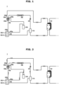
- FIG. 1 is a configuration diagram of a heat pump system, according to an embodiment.
- a heat pump system 1 may include a compressor 102, a water heat exchanger 112, an expansion valve 110, an outdoor heat exchanger 108, a flow path switching valve 106 and an accumulator 104.
- the compressor 102 compresses a low-temperature and low-pressure refrigerant drawn in through an inlet 102a to form a high-temperature and high-pressure refrigerant, and discharges the high-temperature and high-pressure refrigerant through an outlet 102b.
- the compressor 102 may be configured as an inverter compressor with the compression capacity varying by input frequency, or may be configured as a combination of a plurality of constant-speed compressors having constant compression capacity.
- the inlet 102a of the compressor 102 is connected to the accumulator 104, and the outlet 102b of the compressor 102 is connected to the flow path switching valve 106.
- the flow path switching valve 106 is also connected to the accumulator 104.
- the accumulator 104 may be installed between the inlet 102a of the compressor 102 and the flow path switching valve 106.
- the accumulator 104 may temporarily store a mixture of oil and refrigerant when a condensed liquid refrigerant flows in through the flow path switching valve 106, and prevent the liquid refrigerant from being drawn into the compressor 102 by separating the liquid refrigerant not yet evaporated, thereby preventing the compressor 102 from being damaged.
- a gas refrigerant separated in the accumulator 104 is drawn into the inlet 102a of the compressor 102.
- the flow path switching valve 106 may be configured with a four-way valve, which may form a refrigerant flow path required for operation in the corresponding mode by switching flows of the refrigerant discharged from the compressor 102 depending on the operation mode (cooling or heating).
- the flow path switching valve 106 may include a first port 106a connected to the outlet 102b of the compressor 100, a second port 106b connected to the outdoor heat exchanger 108, a third port 106c connected to the water heat exchanger 112, and a fourth port 106d connected to the accumulator 104 on a side of the inlet 102a of the compressor 100.
- the outdoor heat exchanger 108 operates as a condenser in the cooling mode and operates as an evaporator in the heating mode.
- An end of the outdoor heat exchanger 108 is connected to the first expansion valve 110.
- An outdoor fan 109 may be installed in the outdoor heat exchanger 108 to increase heat exchange efficiency between the refrigerant and outdoor air.
- the expansion valve 110 may be configured as an electronic expansion valve, which may expand the refrigerant, control the flow rate of the refrigerant, and when needed, block the flow of the refrigerant.
- the expansion valve 110 may be replaced by an expansion device having a different structure but performing the same function.
- the water heat exchanger 112 may receive the refrigerant compressed in the compressor 102.
- the cold water/hot water produced in the water heat exchanger 112 is supplied to a water supply tank, a fan coil unit, a floor cooling/heating device, etc., and used for cold water/hot water supply and cooling/heating.
- FIG. 2 is a diagram illustrating flows of a refrigerant in a heat pump system, according to an embodiment.
- a main object of the disclosure is to supply hot water by heat exchange between refrigerant and water, so a refrigerant cycle for operation in the heating mode will be focused in the following description.
- the controller 140 may operate the flow path switching valve 106 so that a refrigerant flow path having the first port 106a connected to the third port 106c and the second port 106b connected to the fourth port 106 may be formed.
- the refrigerant discharged from the compressor 102 may flow into the water heat exchanger 112 through the flow path switching valve 106.
- the refrigerant flowing into the water heat exchanger 112 flows into the outdoor heat exchanger 108 via the water heat exchanger 112.
- the refrigerant having passed the outdoor heat exchanger 108 may go through the flow path switching valve 106 again and may be drawn into the compressor 102.
- the heat pump system 1 may form a refrigerant cycle that goes through a sequence of the compressor 102 --> the flow path switching valve 106 --> the water heat exchanger 112 --> the expansion valve 110 --> the outdoor heat exchanger 108 --> the flow path switching valve 106 --> the accumulator 104 --> the compressor 102 to perform heating operation.
- the heat pump system 1 of the disclosure may further include a supercooling heat exchanger 114.
- the supercooling heat exchanger 114 may be located between the water heat exchanger 112 and the expansion valve 110 to make the refrigerant flow into the compressor 102.
- the compressor 102 may perform two-stage refrigerant compression.
- the compressor 102 may include a first compressor 102-1 having the refrigerant that has passed the water heat exchanger 112 flow thereto and compressed therein, and a second compressor 102-2 having both the refrigerant that has passed the first compressor 102-1 and the refrigerant branched and injected from the supercooling heat exchanger 114 located between the water heat exchanger 112 and the expansion valve 110 flow thereto and compressed therein.
- Refrigerant injection into the compressor 102 by the supercooling heat exchanger 114 may be performed by singling out the refrigerant that has passed the water heat exchanger 112 and injecting (only) a steamed or two-phase refrigerant into an injection port of the compressor 102.
- the compressor 102 may compress not only the refrigerant that has passed the water heat exchanger 112 as in the existing cycle but also an extra refrigerant branched and injected from the supercooling heat exchanger 114.
- the efficiency of the compressor 102 may increase by supplying the steamed refrigerant into the injection port of the compressor 102, and the capacity of the condenser may increase by increasing the flow rate of the refrigerant on the side of the condenser. Furthermore, efficient operation may be performed by further securing the degree of subcooling of the refrigerant on the discharge side in the water heat exchanger 112 (or internal heat exchanger). In addition, the discharge temperature of the compressor 102 may be reduced, thereby increasing the operation range.
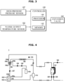
- FIG. 3 is a control block diagram of a heat pump system, according to an embodiment.
- the heat pump system 1 may further include a supercooling temperature sensor 120, a high-pressure pressure sensor 127, a water output temperature sensor 122 and the controller 140, and the controller 140 may include a processor 141 and a memory 142.
- the high-pressure pressure sensor 127 may detect the pressure of the refrigerant discharged by the compressor 102, and figure out a condensation temperature by calculation of saturation temperature from the pressure.
- the supercooling temperature sensor 120 may detect a temperature of the refrigerant supercooled while exchanging heat with water in the process of passing through the water heat exchanger 112.
- the water output temperature sensor 122 may detect a temperature of the water with which heat is exchanged in the process of passing through the water heat exchanger 112.
- the expansion valve 110 may expand the refrigerant condensed after having passed the water heat exchanger 112, as described above.
- the controller 140 may include the memory 142 for storing a control program and control data to control the expansion valve 110 and the processor 141 for generating control signals according to the control program and control data stored in the memory 142.
- the memory 142 and the processor 141 may be implemented integrally or separately.
- the memory 142 may store temperature and pressure detected by various sensors, and first to fifth constants, as will be described later, in addition to the program and data for controlling the expansion valve 110.
- the memory 142 may include a volatile memory 142 for temporarily storing data, such as a static random access memory (SRAM), a dynamic random access memory (DRAM), or the like.
- the memory 142 may also include a non-volatile memory 142 for storing data for a long time, such as a read-only memory (ROM), an erasable programmable ROM (EPROM), an electrically erasable programmable ROM (EEPROM), etc.
- ROM read-only memory
- EPROM erasable programmable ROM
- EEPROM electrically erasable programmable ROM
- the processor 141 may include many different logic circuits and operation circuits, process data according to the program provided in the memory 142, and generate control signals according to the processing results.
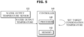
- the controller 140 may receive information about a water output temperature detected from the water output temperature sensor 122 that detects the temperature of the water having gone through heat exchange in the water heat exchanger 112.
- the controller 140 may determine a target condensation temperature of the refrigerant based on the information about the water output temperature.
- the controller 140 may set a value obtained by adding the first constant to the current water output temperature to the target condensation temperature.
- the first constant will be described later.
- the controller 140 may compare the determined target condensation temperature with a current condensation temperature of the refrigerant detected by the high pressure sensor 127, and control the pressure of the refrigerant by controlling the opening degree of the expansion valve 110 based on a result of the comparing.
- the controller 140 uses information detected by various sensors in setting the target condensation temperature, and in this regard, the plurality of sensors included in the heat pump system 1 will be described first before a procedure for controlling the expansion valve 110 is described.
- FIG. 4 illustrates a plurality of sensors included in a heat pump system, according to an embodiment.
- the heat pump system 1 may further include an outdoor temperature sensor 124, an input water temperature sensor 126, a low-pressure temperature sensor 128, a low-pressure pressure sensor 130, a supercooling temperature sensor 120 in addition to the aforementioned high-pressure pressure sensor 127 and the water output temperature sensor 122.
- the outdoor temperature sensor 124 may detect the temperature of outdoor air, and the input water temperature sensor 126 may detect the temperature of water flowing into the water heat exchanger 112 before the water exchanges heat with the refrigerant in the water heat exchanger 112.
- the low-pressure temperature sensor 128 and the low-pressure pressure sensor 130 may detect temperature and pressure of the refrigerant in a low-pressure state before the refrigerant having passed the outdoor heat exchanger 108 is compressed in the compressor 102.
- Various information detected by the plurality of sensors may be used in the control procedure of the controller 140, which will be described below in detail.
- FIG. 5 illustrates a controller setting a target condensation temperature, according to an embodiment
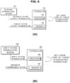
- FIG. 6 illustrates a controller setting an upper limit and a lower limit of a target condensation temperature, according to an embodiment.
- FIG. 7 illustrates a target condensation temperature, according to an embodiment.
- the controller 140 may receive information about a water output temperature detected from the water output temperature sensor 122, and based on this, determine a target condensation temperature.
- the target condensation temperature may be set to be a value obtained by adding the first constant to a current water output temperature detected by the water output temperature sensor 122.
- the target condensation temperature may be limited depending on the input/output water temperature, the minimum compression ratio and an operating section of the compressor 102, and taking these into account, the controller 140 may set an upper limit and a lower limit of the target condensation temperature.
- the controller 140 may receive information about the outdoor temperature detected by the outdoor temperature sensor 124, and determine a maximum water output temperature, which is a highest temperature of the water having gone through heat exchange in the water heat exchanger 112 based on the outdoor temperature.
- the controller 140 may set an upper limit of the target condensation temperature based on the determined maximum water output temperature and the target water output temperature.
- the controller 140 may set a lower one of a value obtained by adding the second constant to the maximum water output temperature based on the outdoor temperature detected by the outdoor temperature sensor 124 and a value obtained by adding the third constant to the target water output temperature to an upper limit of the target condensation temperature.
- the controller 140 may receive information about an input water temperature detected by the input water temperature sensor 126. Based on the input water temperature and the minimum compression ratio of the compressor 102, a lower limit of the target condensation temperature may be set.
- the controller 140 may set a higher one of a value obtained by adding the fourth constant to the input water temperature detected by the input water temperature sensor 126 and a value obtained by multiplying a value obtained by adding the fifth constant to the minimum compression ratio by a low absolute pressure to a lower limit of the target condensation temperature.
- the aforementioned first to fifth constants are denoted as A1 to A5 in FIG. 7 , which may be constant values determined based on a deviation between actual temperature and detected temperature and an optimal condensation temperature. Furthermore, the values may range between -5 and +5.
- the controller 140 may determine the target condensation temperature of the refrigerant to be condensed through heat exchange in the water heat exchanger 112 based on the information detected by each of the plurality of sensors, and may set an upper limit and a lower limit of the target condensation temperature.
- FIG. 8 illustrates how to control the opening degree of an expansion valve depending on condensation temperature, according to an embodiment.
- the expansion valve 110 may expand the refrigerant having passed the water heat exchanger 112, control the flow rate of the refrigerant, and when needed, block the flow of the refrigerant.
- the controller 140 may control the pressure of the refrigerant by controlling the opening degree of the expansion valve 110 to control the expansion degree of the refrigerant.
- the opening degree of the expansion valve 110 decreases, the pressure of the refrigerant increases, and accordingly, the condensation temperature of the refrigerant increases as well.
- the target condensation temperature may be compared with the current condensation temperature and the opening degree of the expansion valve 110 may be increased or reduced depending on the result of the comparing.
- the controller 140 may compare the target condensation temperature with the current condensation temperature of the high-pressure pressure sensor 127, and control the expansion valve 110 to increase the opening degree of the expansion valve 110 when the current condensation temperature based on the detection result of the high-pressure pressure sensor 127 is higher than the target condensation temperature. That is, increasing the opening degree of the expansion valve 110 may further expand the refrigerant and thus, reduce the condensation temperature of the refrigerant.
- the controller 140 may compare the target condensation temperature with the current condensation temperature, and control the expansion valve 110 to reduce the opening degree of the expansion valve 110 when the current condensation temperature based on the detection result of the condensation temperature of the high-pressure pressure sensor 127 is lower than the target condensation temperature. That is, decreasing the opening degree of the expansion valve 110 may less expand the refrigerant and thus, increase the condensation temperature of the refrigerant.
- controller 140 may compare the target condensation temperature with the current condensation temperature, and control the expansion valve 110 to maintain the current opening degree when the current condensation temperature based on the detection result of the condensation temperature of the high-pressure pressure sensor 127 is equal to the target condensation temperature.
- FIG. 9 is a control block diagram of a heat pump system, according to another embodiment.
- the heat pump system 1 may further include the accumulator 104 for temporarily storing the refrigerant and separating the refrigerant in the liquid state not yet evaporated.
- the controller 140 may control the expansion valve 110 not to reduce the opening degree of the expansion valve 110 when it is determined that there is no refrigerant in the accumulator 104.
- the high pressure of the refrigerant that has passed the compressor 102 may increase, causing the refrigerant to be overheated, so the opening degree of the expansion valve 110 may be controlled not to be reduced so as to increase the flow rate of the refrigerant.
- the aforementioned low-pressure temperature sensor 128 and the low-pressure pressure sensor 130 may detect the temperature and the pressure of the refrigerant before the refrigerant passes the compressor 102, and the controller 140 may receive the detected information.
- the controller 140 may control the opening degree of the expansion valve 110 based on a difference between the low-pressure temperature detected by the low-pressure temperature sensor 128 and a low-pressure saturation temperature based on the pressure detected by the low-pressure pressure sensor 130.
- the controller 140 may determine that the refrigerant is overheated when the low-pressure temperature is determined to be higher than the low-pressure saturation temperature, and to correct this, control the expansion valve 110 to prevent the opening degree of the expansion valve 110 from being further reduced and also control a low-pressure superheat degree. This may prevent the refrigerant from being superheated.
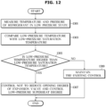
- FIG. 10 is flowchart illustrating a method of controlling a heat pump system, according to an embodiment.
- the high-pressure pressure sensor 127 may detect temperature of the refrigerant to be condensed in the water heat exchanger 112 in 1101, and the water output temperature sensor 122 may detect the temperature of water that has gone through heat exchange in the water heat exchanger 112 in 1103.
- the controller 140 may determine a target condensation temperature of the refrigerant based on the temperature of the water that has gone through heat exchange, which is detected by the water output temperature sensor 122, in 1105.
- the controller 140 may compare the determined target condensation temperature with the temperature of the condensed refrigerant detected by the high-pressure sensor 127 in 1107, and control the opening degree of the expansion valve 110 based on a result of the comparing in 1109.
- the target condensation temperature may be set to be a value obtained by adding the first constant to a current water output temperature detected by the water output temperature sensor 122.
- controller 140 may set an upper limit of the target condensation temperature based on the determined maximum water output temperature and the target water output temperature.
- the controller 140 may set a lower one of a value obtained by adding the second constant to the maximum water output temperature based on the outdoor temperature detected by the outdoor temperature sensor 124 and a value obtained by adding the third constant to the target water output temperature to an upper limit of the target condensation temperature.
- the controller 140 may receive information about an input water temperature detected by the input water temperature sensor 126. Based on the input water temperature and a minimum compression ratio of the compressor 102, a lower limit of the target condensation temperature may be set.
- the controller 140 may set a higher one of a value obtained by adding the fourth constant to the input water temperature detected by the input water temperature sensor 126 and a value obtained by multiplying a value obtained by adding the fifth constant to the minimum compression ratio by a low absolute pressure to a lower limit of the target condensation temperature.
- the aforementioned first to fifth constants are indicated as A1 to A5 in FIG. 7 , which may be constant values determined based on a deviation between actual temperature and detected temperature and an optimal condensation temperature. Furthermore, the values may range between -5 and +5.
- the controller 140 may determine the target condensation temperature of the refrigerant to be condensed through heat exchange in the water heat exchanger 112 based on the information detected by each of the plurality of sensors, and may set an upper limit and a lower limit of the target condensation temperature, and control the opening degree of the expansion valve 110 by comparing the target condensation temperature with the current condensation temperature.
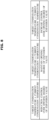
- FIG. 11 is flowchart illustrating a method of controlling a heat pump system, according to an embodiment.
- the controller 140 may control the opening degree of the expansion valve 110 by comparing the target condensation temperature with the current condensation temperature.
- the opening degree of the expansion valve 110 decreases, the pressure of the refrigerant increases, and accordingly, the condensation temperature of the refrigerant increases as well.
- the target condensation temperature may be compared with the current condensation temperature and the opening degree of the expansion valve 110 may be increased or reduced depending on the result of the comparing.
- the controller 140 may compare the target condensation temperature with the current condensation temperature in 1201, and control the expansion valve 110 to increase the opening degree of the expansion valve 110 when the current condensation temperature based on the detection result of the high-pressure pressure sensor 127 is higher than the target condensation temperature in 1203. That is, increasing the opening degree of the expansion valve 110 may further expand the refrigerant and thus, reduce the condensation temperature of the refrigerant.
- the controller 140 may compare the target condensation temperature with the current condensation temperature in 1201, and control the expansion valve 110 to reduce the opening degree of the expansion valve 110 when the current condensation temperature is not higher than the target condensation temperature in 1203 and the current condensation temperature based on the detection result of the high-pressure pressure sensor 127 is lower than the target condensation temperature in 1205. That is, decreasing the opening degree of the expansion valve 110 may less expand the refrigerant and thus, increase the condensation temperature of the refrigerant.
- the controller 140 may control the expansion valve 110 to maintain the current opening degree of the expansion valve 110.
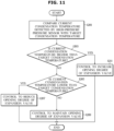
- FIG. 12 is a flowchart illustrating a method of controlling a heat pump system, according to another embodiment.
- the controller 140 may control the expansion valve 110 not to reduce the opening degree of the expansion valve 110 so as to increase the flow rate of the refrigerant.
- the low-pressure temperature sensor 128 and the low-pressure pressure sensor 130 may detect temperature and pressure of the refrigerant in a low pressure state before passing through the compressor 102, in 1301.
- the controller 140 may compare the low-pressure temperature detected by the low-pressure temperature sensor 128 and a low-pressure saturation temperature based on the pressure detected by the low-pressure pressure sensor 130, in 1303.
- the expansion valve 110 may be controlled not to reduce the opening degree of the expansion valve 110 and a low-pressure superheat degree may also be controlled in 1307.
- the controller 140 may maintain the existing control in 1309.
- expansion valve control is performed based on a target condensation temperature to attain hot water output, increase operation reliability under low/high temperature outdoor conditions, and perform a heating operation at an optimal efficiency.
- the embodiments of the disclosure may be implemented in the form of a recording medium for storing instructions to be carried out by a computer.
- the instructions may be stored in the form of program codes, and when executed by a processor, may generate program modules to perform operations in the embodiments of the disclosure.
- the recording media may correspond to computer-readable recording media.
- the computer-readable recording medium includes any type of recording medium having data stored thereon that may be thereafter read by a computer.
- a computer may be a read only memory (ROM), a random access memory (RAM), a magnetic tape, a magnetic disk, a flash memory, an optical data storage device, etc.
Landscapes
- Engineering & Computer Science (AREA)
- Physics & Mathematics (AREA)
- Mechanical Engineering (AREA)
- Thermal Sciences (AREA)
- General Engineering & Computer Science (AREA)
- Chemical & Material Sciences (AREA)
- Combustion & Propulsion (AREA)
- Analytical Chemistry (AREA)
- Power Engineering (AREA)
- Computer Hardware Design (AREA)
- Heat-Pump Type And Storage Water Heaters (AREA)
- Air Conditioning Control Device (AREA)
Applications Claiming Priority (2)
| Application Number | Priority Date | Filing Date | Title |
|---|---|---|---|
| KR1020220031863A KR20230134730A (ko) | 2022-03-15 | 2022-03-15 | 히트 펌프 시스템 및 그 제어 방법 |
| PCT/KR2023/002123 WO2023177092A1 (ko) | 2022-03-15 | 2023-02-14 | 히트 펌프 시스템 및 그 제어 방법 |
Publications (2)
| Publication Number | Publication Date |
|---|---|
| EP4477973A1 true EP4477973A1 (de) | 2024-12-18 |
| EP4477973A4 EP4477973A4 (de) | 2025-06-25 |
Family
ID=88023600
Family Applications (1)
| Application Number | Title | Priority Date | Filing Date |
|---|---|---|---|
| EP23770972.0A Pending EP4477973A4 (de) | 2022-03-15 | 2023-02-14 | Wärmepumpensystem und steuerungsverfahren dafür |
Country Status (5)
| Country | Link |
|---|---|
| US (1) | US20240401855A1 (de) |
| EP (1) | EP4477973A4 (de) |
| KR (1) | KR20230134730A (de) |
| CN (1) | CN118829836A (de) |
| WO (1) | WO2023177092A1 (de) |
Cited By (1)
| Publication number | Priority date | Publication date | Assignee | Title |
|---|---|---|---|---|
| CN119594542A (zh) * | 2024-12-23 | 2025-03-11 | 珠海格力电器股份有限公司 | 多模块空调机组的控制方法、装置和多模块空调机组 |
Families Citing this family (1)
| Publication number | Priority date | Publication date | Assignee | Title |
|---|---|---|---|---|
| KR20250052664A (ko) * | 2023-10-12 | 2025-04-21 | 삼성전자주식회사 | 히트 펌프 시스템 및 히트 펌프 시스템의 제어 방법 |
Family Cites Families (7)
| Publication number | Priority date | Publication date | Assignee | Title |
|---|---|---|---|---|
| KR100205235B1 (ko) * | 1996-11-12 | 1999-07-01 | 김덕중 | 자동차 자동온도 제어 시스템 및 방법 |
| JP4436356B2 (ja) * | 2006-12-25 | 2010-03-24 | 三星電子株式会社 | 空気調和機 |
| JP2008232508A (ja) * | 2007-03-19 | 2008-10-02 | Mitsubishi Electric Corp | 給湯器 |
| EP2653805B1 (de) * | 2010-12-15 | 2018-11-14 | Mitsubishi Electric Corporation | Kombination aus klimaanlage und heisswasserversorgungssystem |
| KR101591191B1 (ko) * | 2014-08-14 | 2016-02-02 | 엘지전자 주식회사 | 공기 조화기 및 그 제어방법 |
| KR102353913B1 (ko) * | 2017-04-25 | 2022-01-21 | 삼성전자주식회사 | 공기 조화 시스템 및 그 제어 방법 |
| KR102662870B1 (ko) * | 2019-08-30 | 2024-05-07 | 삼성전자주식회사 | 공기 조화기 및 그 제어 방법 |
-
2022
- 2022-03-15 KR KR1020220031863A patent/KR20230134730A/ko active Pending
-
2023
- 2023-02-14 CN CN202380025524.3A patent/CN118829836A/zh active Pending
- 2023-02-14 EP EP23770972.0A patent/EP4477973A4/de active Pending
- 2023-02-14 WO PCT/KR2023/002123 patent/WO2023177092A1/ko not_active Ceased
-
2024
- 2024-08-13 US US18/802,836 patent/US20240401855A1/en active Pending
Cited By (1)
| Publication number | Priority date | Publication date | Assignee | Title |
|---|---|---|---|---|
| CN119594542A (zh) * | 2024-12-23 | 2025-03-11 | 珠海格力电器股份有限公司 | 多模块空调机组的控制方法、装置和多模块空调机组 |
Also Published As
| Publication number | Publication date |
|---|---|
| US20240401855A1 (en) | 2024-12-05 |
| CN118829836A (zh) | 2024-10-22 |
| EP4477973A4 (de) | 2025-06-25 |
| KR20230134730A (ko) | 2023-09-22 |
| WO2023177092A1 (ko) | 2023-09-21 |
Similar Documents
| Publication | Publication Date | Title |
|---|---|---|
| US20240401855A1 (en) | Heat pump system and control method thereof | |
| CN101469915B (zh) | 空调系统 | |
| KR101585943B1 (ko) | 공기조화기 및 그 제어방법 | |
| EP2587193A2 (de) | Klimaanlage | |
| CN107421176B (zh) | 电子膨胀阀的控制方法及热泵系统 | |
| KR20070065417A (ko) | 냉동 공조장치, 냉동 공조장치의 운전 제어 방법, 냉동공조장치의 냉매량 제어 방법 | |
| US20210055024A1 (en) | Air-conditioning apparatus | |
| KR20150057624A (ko) | 공기 조화기 및 그 제어방법 | |
| US11512880B2 (en) | Refrigeration cycle device | |
| EP3260792B1 (de) | Klimatisierungssystemsteuerungsvorrichtung, klimatisierungssystem, klimatisierungsteuerungsprogramm und klimatisierungssystemsteuerungsverfahren | |
| CN111503854B (zh) | 空调系统及其防凝露控制方法和装置、存储介质 | |
| EP3594587B1 (de) | Wärmepumpenvorrichtung zur warmwasserversorgung | |
| KR102165354B1 (ko) | 공기조화기 및 그 제어방법 | |
| WO2017094172A1 (ja) | 空気調和装置 | |
| KR20210073990A (ko) | 히트펌프시스템 | |
| Shen et al. | Cold climate heat pumps using tandem compressors | |
| KR101973202B1 (ko) | 공기 조화기 | |
| JP2019095128A (ja) | ヒートポンプ装置の制御方法、及びヒートポンプ装置 | |
| EP4664039A1 (de) | Wärmepumpensystem und steuerungsverfahren dafür | |
| US20250020377A1 (en) | Heat pump system and method for controlling the same | |
| US12339026B2 (en) | Air-conditioner | |
| US20220186993A1 (en) | Air-conditioning apparatus | |
| KR20240032592A (ko) | 히트 펌프 시스템 및 그 제어 방법 | |
| KR102559522B1 (ko) | 공기 조화 장치 및 이의 제어 방법 | |
| EP4563918A1 (de) | Wärmepumpensystem und steuerungsverfahren dafür |
Legal Events
| Date | Code | Title | Description |
|---|---|---|---|
| STAA | Information on the status of an ep patent application or granted ep patent |
Free format text: STATUS: THE INTERNATIONAL PUBLICATION HAS BEEN MADE |
|
| PUAI | Public reference made under article 153(3) epc to a published international application that has entered the european phase |
Free format text: ORIGINAL CODE: 0009012 |
|
| STAA | Information on the status of an ep patent application or granted ep patent |
Free format text: STATUS: REQUEST FOR EXAMINATION WAS MADE |
|
| 17P | Request for examination filed |
Effective date: 20240910 |
|
| AK | Designated contracting states |
Kind code of ref document: A1 Designated state(s): AL AT BE BG CH CY CZ DE DK EE ES FI FR GB GR HR HU IE IS IT LI LT LU LV MC ME MK MT NL NO PL PT RO RS SE SI SK SM TR |
|
| DAV | Request for validation of the european patent (deleted) | ||
| DAX | Request for extension of the european patent (deleted) | ||
| A4 | Supplementary search report drawn up and despatched |
Effective date: 20250521 |
|
| RIC1 | Information provided on ipc code assigned before grant |
Ipc: F24D 17/02 20060101ALI20250516BHEP Ipc: F25B 43/00 20060101ALI20250516BHEP Ipc: F25B 1/10 20060101ALI20250516BHEP Ipc: F25B 13/00 20060101ALI20250516BHEP Ipc: F25B 30/02 20060101ALI20250516BHEP Ipc: F25B 49/02 20060101AFI20250516BHEP |