EP4477920A1 - Gearbox assembly and power train assembly for a vehicle axle, and related vehicle - Google Patents
Gearbox assembly and power train assembly for a vehicle axle, and related vehicle Download PDFInfo
- Publication number
- EP4477920A1 EP4477920A1 EP23179029.6A EP23179029A EP4477920A1 EP 4477920 A1 EP4477920 A1 EP 4477920A1 EP 23179029 A EP23179029 A EP 23179029A EP 4477920 A1 EP4477920 A1 EP 4477920A1
- Authority
- EP
- European Patent Office
- Prior art keywords
- gear
- countershaft
- assembly
- rotation axis
- gearbox assembly
- Prior art date
- Legal status (The legal status is an assumption and is not a legal conclusion. Google has not performed a legal analysis and makes no representation as to the accuracy of the status listed.)
- Pending
Links
Images


Classifications
-
- B—PERFORMING OPERATIONS; TRANSPORTING
- B60—VEHICLES IN GENERAL
- B60K—ARRANGEMENT OR MOUNTING OF PROPULSION UNITS OR OF TRANSMISSIONS IN VEHICLES; ARRANGEMENT OR MOUNTING OF PLURAL DIVERSE PRIME-MOVERS IN VEHICLES; AUXILIARY DRIVES FOR VEHICLES; INSTRUMENTATION OR DASHBOARDS FOR VEHICLES; ARRANGEMENTS IN CONNECTION WITH COOLING, AIR INTAKE, GAS EXHAUST OR FUEL SUPPLY OF PROPULSION UNITS IN VEHICLES
- B60K17/00—Arrangement or mounting of transmissions in vehicles
- B60K17/04—Arrangement or mounting of transmissions in vehicles characterised by arrangement, location or kind of gearing
- B60K17/06—Arrangement or mounting of transmissions in vehicles characterised by arrangement, location or kind of gearing of change-speed gearing
-
- F—MECHANICAL ENGINEERING; LIGHTING; HEATING; WEAPONS; BLASTING
- F16—ENGINEERING ELEMENTS AND UNITS; GENERAL MEASURES FOR PRODUCING AND MAINTAINING EFFECTIVE FUNCTIONING OF MACHINES OR INSTALLATIONS; THERMAL INSULATION IN GENERAL
- F16H—GEARING
- F16H1/00—Toothed gearings for conveying rotary motion
- F16H1/28—Toothed gearings for conveying rotary motion with gears having orbital motion
- F16H1/32—Toothed gearings for conveying rotary motion with gears having orbital motion in which the central axis of the gearing lies inside the periphery of an orbital gear
-
- B—PERFORMING OPERATIONS; TRANSPORTING
- B60—VEHICLES IN GENERAL
- B60B—VEHICLE WHEELS; CASTORS; AXLES FOR WHEELS OR CASTORS; INCREASING WHEEL ADHESION
- B60B35/00—Axle units; Parts thereof ; Arrangements for lubrication of axles
- B60B35/12—Torque-transmitting axles
- B60B35/121—Power-transmission from drive shaft to hub
- B60B35/122—Power-transmission from drive shaft to hub using gearings
-
- B—PERFORMING OPERATIONS; TRANSPORTING
- B60—VEHICLES IN GENERAL
- B60K—ARRANGEMENT OR MOUNTING OF PROPULSION UNITS OR OF TRANSMISSIONS IN VEHICLES; ARRANGEMENT OR MOUNTING OF PLURAL DIVERSE PRIME-MOVERS IN VEHICLES; AUXILIARY DRIVES FOR VEHICLES; INSTRUMENTATION OR DASHBOARDS FOR VEHICLES; ARRANGEMENTS IN CONNECTION WITH COOLING, AIR INTAKE, GAS EXHAUST OR FUEL SUPPLY OF PROPULSION UNITS IN VEHICLES
- B60K1/00—Arrangement or mounting of electrical propulsion units
-
- B—PERFORMING OPERATIONS; TRANSPORTING
- B60—VEHICLES IN GENERAL
- B60K—ARRANGEMENT OR MOUNTING OF PROPULSION UNITS OR OF TRANSMISSIONS IN VEHICLES; ARRANGEMENT OR MOUNTING OF PLURAL DIVERSE PRIME-MOVERS IN VEHICLES; AUXILIARY DRIVES FOR VEHICLES; INSTRUMENTATION OR DASHBOARDS FOR VEHICLES; ARRANGEMENTS IN CONNECTION WITH COOLING, AIR INTAKE, GAS EXHAUST OR FUEL SUPPLY OF PROPULSION UNITS IN VEHICLES
- B60K17/00—Arrangement or mounting of transmissions in vehicles
- B60K17/02—Arrangement or mounting of transmissions in vehicles characterised by arrangement, location, or kind of clutch
-
- B—PERFORMING OPERATIONS; TRANSPORTING
- B60—VEHICLES IN GENERAL
- B60K—ARRANGEMENT OR MOUNTING OF PROPULSION UNITS OR OF TRANSMISSIONS IN VEHICLES; ARRANGEMENT OR MOUNTING OF PLURAL DIVERSE PRIME-MOVERS IN VEHICLES; AUXILIARY DRIVES FOR VEHICLES; INSTRUMENTATION OR DASHBOARDS FOR VEHICLES; ARRANGEMENTS IN CONNECTION WITH COOLING, AIR INTAKE, GAS EXHAUST OR FUEL SUPPLY OF PROPULSION UNITS IN VEHICLES
- B60K17/00—Arrangement or mounting of transmissions in vehicles
- B60K17/04—Arrangement or mounting of transmissions in vehicles characterised by arrangement, location or kind of gearing
- B60K17/16—Arrangement or mounting of transmissions in vehicles characterised by arrangement, location or kind of gearing of differential gearing
- B60K17/165—Arrangement or mounting of transmissions in vehicles characterised by arrangement, location or kind of gearing of differential gearing provided between independent half axles
-
- F—MECHANICAL ENGINEERING; LIGHTING; HEATING; WEAPONS; BLASTING
- F16—ENGINEERING ELEMENTS AND UNITS; GENERAL MEASURES FOR PRODUCING AND MAINTAINING EFFECTIVE FUNCTIONING OF MACHINES OR INSTALLATIONS; THERMAL INSULATION IN GENERAL
- F16H—GEARING
- F16H37/00—Combinations of mechanical gearings, not provided for in groups F16H1/00 - F16H35/00
- F16H37/02—Combinations of mechanical gearings, not provided for in groups F16H1/00 - F16H35/00 comprising essentially only toothed or friction gearings
- F16H37/06—Combinations of mechanical gearings, not provided for in groups F16H1/00 - F16H35/00 comprising essentially only toothed or friction gearings with a plurality of driving or driven shafts; with arrangements for dividing torque between two or more intermediate shafts
- F16H37/08—Combinations of mechanical gearings, not provided for in groups F16H1/00 - F16H35/00 comprising essentially only toothed or friction gearings with a plurality of driving or driven shafts; with arrangements for dividing torque between two or more intermediate shafts with differential gearing
- F16H37/0806—Combinations of mechanical gearings, not provided for in groups F16H1/00 - F16H35/00 comprising essentially only toothed or friction gearings with a plurality of driving or driven shafts; with arrangements for dividing torque between two or more intermediate shafts with differential gearing with a plurality of driving or driven shafts
- F16H37/0813—Combinations of mechanical gearings, not provided for in groups F16H1/00 - F16H35/00 comprising essentially only toothed or friction gearings with a plurality of driving or driven shafts; with arrangements for dividing torque between two or more intermediate shafts with differential gearing with a plurality of driving or driven shafts with only one input shaft
- F16H37/082—Combinations of mechanical gearings, not provided for in groups F16H1/00 - F16H35/00 comprising essentially only toothed or friction gearings with a plurality of driving or driven shafts; with arrangements for dividing torque between two or more intermediate shafts with differential gearing with a plurality of driving or driven shafts with only one input shaft and additional planetary reduction gears
-
- F—MECHANICAL ENGINEERING; LIGHTING; HEATING; WEAPONS; BLASTING
- F16—ENGINEERING ELEMENTS AND UNITS; GENERAL MEASURES FOR PRODUCING AND MAINTAINING EFFECTIVE FUNCTIONING OF MACHINES OR INSTALLATIONS; THERMAL INSULATION IN GENERAL
- F16H—GEARING
- F16H57/00—General details of gearing
- F16H57/02—Gearboxes; Mounting gearing therein
-
- F—MECHANICAL ENGINEERING; LIGHTING; HEATING; WEAPONS; BLASTING
- F16—ENGINEERING ELEMENTS AND UNITS; GENERAL MEASURES FOR PRODUCING AND MAINTAINING EFFECTIVE FUNCTIONING OF MACHINES OR INSTALLATIONS; THERMAL INSULATION IN GENERAL
- F16H—GEARING
- F16H57/00—General details of gearing
- F16H57/02—Gearboxes; Mounting gearing therein
- F16H57/023—Mounting or installation of gears or shafts in the gearboxes, e.g. methods or means for assembly
-
- F—MECHANICAL ENGINEERING; LIGHTING; HEATING; WEAPONS; BLASTING
- F16—ENGINEERING ELEMENTS AND UNITS; GENERAL MEASURES FOR PRODUCING AND MAINTAINING EFFECTIVE FUNCTIONING OF MACHINES OR INSTALLATIONS; THERMAL INSULATION IN GENERAL
- F16H—GEARING
- F16H57/00—General details of gearing
- F16H57/08—General details of gearing of gearings with members having orbital motion
-
- F—MECHANICAL ENGINEERING; LIGHTING; HEATING; WEAPONS; BLASTING
- F16—ENGINEERING ELEMENTS AND UNITS; GENERAL MEASURES FOR PRODUCING AND MAINTAINING EFFECTIVE FUNCTIONING OF MACHINES OR INSTALLATIONS; THERMAL INSULATION IN GENERAL
- F16H—GEARING
- F16H57/00—General details of gearing
- F16H57/08—General details of gearing of gearings with members having orbital motion
- F16H57/082—Planet carriers
-
- B—PERFORMING OPERATIONS; TRANSPORTING
- B60—VEHICLES IN GENERAL
- B60K—ARRANGEMENT OR MOUNTING OF PROPULSION UNITS OR OF TRANSMISSIONS IN VEHICLES; ARRANGEMENT OR MOUNTING OF PLURAL DIVERSE PRIME-MOVERS IN VEHICLES; AUXILIARY DRIVES FOR VEHICLES; INSTRUMENTATION OR DASHBOARDS FOR VEHICLES; ARRANGEMENTS IN CONNECTION WITH COOLING, AIR INTAKE, GAS EXHAUST OR FUEL SUPPLY OF PROPULSION UNITS IN VEHICLES
- B60K1/00—Arrangement or mounting of electrical propulsion units
- B60K2001/001—Arrangement or mounting of electrical propulsion units one motor mounted on a propulsion axle for rotating right and left wheels of this axle
-
- B—PERFORMING OPERATIONS; TRANSPORTING
- B60—VEHICLES IN GENERAL
- B60Y—INDEXING SCHEME RELATING TO ASPECTS CROSS-CUTTING VEHICLE TECHNOLOGY
- B60Y2200/00—Type of vehicle
- B60Y2200/10—Road Vehicles
- B60Y2200/14—Trucks; Load vehicles, Busses
-
- B—PERFORMING OPERATIONS; TRANSPORTING
- B60—VEHICLES IN GENERAL
- B60Y—INDEXING SCHEME RELATING TO ASPECTS CROSS-CUTTING VEHICLE TECHNOLOGY
- B60Y2400/00—Special features of vehicle units
- B60Y2400/40—Actuators for moving a controlled member
-
- F—MECHANICAL ENGINEERING; LIGHTING; HEATING; WEAPONS; BLASTING
- F16—ENGINEERING ELEMENTS AND UNITS; GENERAL MEASURES FOR PRODUCING AND MAINTAINING EFFECTIVE FUNCTIONING OF MACHINES OR INSTALLATIONS; THERMAL INSULATION IN GENERAL
- F16H—GEARING
- F16H48/00—Differential gearings
- F16H48/20—Arrangements for suppressing or influencing the differential action, e.g. locking devices
- F16H2048/201—Arrangements for suppressing or influencing the differential action, e.g. locking devices with means directly braking the orbital gears
-
- F—MECHANICAL ENGINEERING; LIGHTING; HEATING; WEAPONS; BLASTING
- F16—ENGINEERING ELEMENTS AND UNITS; GENERAL MEASURES FOR PRODUCING AND MAINTAINING EFFECTIVE FUNCTIONING OF MACHINES OR INSTALLATIONS; THERMAL INSULATION IN GENERAL
- F16H—GEARING
- F16H57/00—General details of gearing
- F16H57/02—Gearboxes; Mounting gearing therein
- F16H2057/02039—Gearboxes for particular applications
- F16H2057/02043—Gearboxes for particular applications for vehicle transmissions
-
- F—MECHANICAL ENGINEERING; LIGHTING; HEATING; WEAPONS; BLASTING
- F16—ENGINEERING ELEMENTS AND UNITS; GENERAL MEASURES FOR PRODUCING AND MAINTAINING EFFECTIVE FUNCTIONING OF MACHINES OR INSTALLATIONS; THERMAL INSULATION IN GENERAL
- F16H—GEARING
- F16H2200/00—Transmissions for multiple ratios
- F16H2200/0021—Transmissions for multiple ratios specially adapted for electric vehicles
-
- F—MECHANICAL ENGINEERING; LIGHTING; HEATING; WEAPONS; BLASTING
- F16—ENGINEERING ELEMENTS AND UNITS; GENERAL MEASURES FOR PRODUCING AND MAINTAINING EFFECTIVE FUNCTIONING OF MACHINES OR INSTALLATIONS; THERMAL INSULATION IN GENERAL
- F16H—GEARING
- F16H2200/00—Transmissions for multiple ratios
- F16H2200/003—Transmissions for multiple ratios characterised by the number of forward speeds
- F16H2200/0034—Transmissions for multiple ratios characterised by the number of forward speeds the gear ratios comprising two forward speeds
-
- F—MECHANICAL ENGINEERING; LIGHTING; HEATING; WEAPONS; BLASTING
- F16—ENGINEERING ELEMENTS AND UNITS; GENERAL MEASURES FOR PRODUCING AND MAINTAINING EFFECTIVE FUNCTIONING OF MACHINES OR INSTALLATIONS; THERMAL INSULATION IN GENERAL
- F16H—GEARING
- F16H2200/00—Transmissions for multiple ratios
- F16H2200/20—Transmissions using gears with orbital motion
- F16H2200/2002—Transmissions using gears with orbital motion characterised by the number of sets of orbital gears
- F16H2200/2005—Transmissions using gears with orbital motion characterised by the number of sets of orbital gears with one sets of orbital gears
-
- F—MECHANICAL ENGINEERING; LIGHTING; HEATING; WEAPONS; BLASTING
- F16—ENGINEERING ELEMENTS AND UNITS; GENERAL MEASURES FOR PRODUCING AND MAINTAINING EFFECTIVE FUNCTIONING OF MACHINES OR INSTALLATIONS; THERMAL INSULATION IN GENERAL
- F16H—GEARING
- F16H2200/00—Transmissions for multiple ratios
- F16H2200/20—Transmissions using gears with orbital motion
- F16H2200/2094—Transmissions using gears with orbital motion using positive clutches, e.g. dog clutches
Definitions
- the disclosure relates generally to the field of vehicles.
- the disclosure relates to a gearbox assembly and to a powertrain assembly for a vehicle axle, and to a related vehicle.
- the present disclosure is particularly suitable for electrically driven vehicle axles or E-axles, and can be applied to heavy-duty or medium-duty vehicles, e.g. trucks, and will be described herein by making more specific reference to such applications, without intending in any way to restrict its possible applications.
- E-axles are used to drive the wheels of a vehicle, such as of trucks used for example for heavy-duty or medium-duty applications.
- Modem E-axles can be functionally quite effective. However, they are challenging to package within the available space of the vehicle to allow routing of many components needed to support the truck propulsion, such as for instance high voltage cables, brake lines, pneumatics, cooling hoses, harnesses, etc., and actually there is need, desire and room for further improvements in the way they are realized.
- the plurality of countershaft assemblies comprises:
- said first and second countershafts are positioned around the rotation axis along a virtual circumference having, as its center, the rotation axis, with their respective first and second rotation axes that are located diametrically opposite to each other with respect to the rotation axis itself.
- the plurality of countershaft assemblies comprises:
- said first, second and third countershafts are positioned around the rotation axis with their respective rotation axes positioned at the vertices of a substantially equilateral triangle.
- the clutch is positioned between the planet carrier and the differential and is configured to be operated to shift, along the rotation axis, between said first and second positions.
- the clutch comprises or is constituted by a dog clutch.
- the free wheeling gear comprises one or more teeth configured to engage with the clutch in said first position and to be disengaged from the clutch in said second position.
- the gearbox assembly further comprises a coupling gear which is mounted along the vehicle axle concentrically to the rotation axis and is adapted to be operatively connected to said motor.
- the coupling gear is mechanically connected to the sun gear via a coupling member.
- a powertrain assembly for rotating a vehicle axle around a rotation axis, the powertrain assembly comprising
- the motor is an electric motor having a stator and a rotor, wherein the motor is mounted with its rotor rotating about an axis substantially parallel to the rotation axis of the vehicle axle.
- the powertrain assembly further comprises a gear set configured for mechanically coupling an output shaft of the motor with the gearbox assembly.
- the gear set comprises a first gear suitable to be mounted on the output shaft of the motor and a second gear suitable to be positioned between and to engage with both said first gear and said coupling gear of the gearbox assembly.
- the gear set comprises only a first gear suitable to be mounted on the output shaft of the motor and to engage with said coupling gear of the gearbox assembly.
- said motor is an electric motor having a stator and a rotor, wherein the motor is mounted along the vehicle axle with its rotor rotating positioned concentrically to the rotation axis.
- the rotor of said motor is coupled directly with the sun gear.
- a vehicle comprising at least a gearbox assembly or a powertrain assembly as above defined, and in particular as hereinafter described and claimed in the accompanying claims.
- the vehicle is a heavy-duty or medium-duty vehicle.
- the vehicle is a heavy-duty or medium-duty truck.
- a technical benefit may include the possibility of obtaining a flexible and scalable configuration, according to a design that can be properly selected depending on the specific applications, and that in any case is extremely robust, compact and allows for maximum modularity of applications, such as for heavy duty/medium duty applications.
- Another technical benefit may include obtaining a very simple bearing layouts, eliminating or at least reducing the need for bearings supporting the planet carrier, thus leading to simplification and improved float/load share.
- Another technical benefit may include obtaining a simplification of the differential bearings due to the radial force elimination that occurs with a multi-countershaft design. This leads to use of simple bearings not requiring shimming or adjustment.
- Another technical benefit may include the possibility of obtaining multiple speed ratios in an effective and efficient way.
- Another technical benefit may include using simple and already clutch system, with full floating of critical components for example of the planetary system.
- Another technical benefit may include the possibility of obtaining an improved ground clearance and lightweight.
- vehicle axles and in particular electric or E-axle of vehicles, may be somehow difficult and cumbersome to be installed and their structure and configuration may not be flexible enough to be applied to different vehicles.
- a gearbox assembly for a vehicle axle, as well as a powertrain assembly comprising such gearbox assembly, comprising: a planetary gear system suitable to receive power from a motor, in particular an electric motor, associated to and configured for driving the wheels attached at the ends of the vehicle axle, a differential positioned adjacent to the planet carrier of the planetary gear system; a free wheeling gear located concentrically to an output shaft of the planet carrier; a plurality of countershaft assemblies configured for coupling with the free wheeling gear and an output gear of the differential; and a clutch which is configured to be shifted between a first position where it couples the planet carrier with the free wheeling gear, and a second position where it couples the planet carrier with the differential.
- the gearbox assembly and the powertrain assembly according to the disclosure may thus result in obtaining a multi-speed output of the differential, may have a robust and compact structure, and may also have a simplified and modular configuration that may be applied to different vehicles.
- the gearbox assembly 1 is suitable to be installed along a vehicle axle, in particular an E-axle, an example of which is shown in FIG. 7 and (partly) in Fig. 8 , and therein indicated by the overall reference 100.
- the gearbox assembly 1 is shown in the figures coupled to a motor 200 which is suitable to provide the gearbox assembly 1 with the power/torque needed for rotating the wheels.
- the gearbox assembly 1 comprises at least:
- the differential 30 is positioned along the rotation axis X and comprises a shaft member 31 which is positioned along the axle 100, rotating around the rotation axis X, and has a first end which is adjacent to and faces the output member 20 of the planet carrier 18, and an output gear 32 which is positioned, on the shaft member 31, concentrically to the rotation axis X, for instance at a second end of the shaft member 31 opposite to said first end.
- the free wheeling gear 40 is located around and concentrically to the output member 20 of the planet carrier 18.
- the clutch 80 is shown in FIG. 4 in a neutral position and is configured to be operated between a first position, schematically illustrated in figure 6 , where it couples the planet carrier 18, and in particular its output member 20, with the free wheeling gear 40, and a second position, schematically illustrated in figure 5 , where it couples the planet carrier 18, and in particular its output member 20, directly with the differential 30, and in particular with the shaft member 31.
- the clutch 80 is positioned, along the axis X, between the planet carrier 18, and in particular its output member 20, and the differential 30, in particular the first end portion of the shaft member 31, and is configured to be operated to shift, along the rotation axis X, between said first and second positions.
- the clutch 80 comprises or is constituted by a dog clutch.
- the free wheeling gear 40 comprises one or more teeth configured to engage with the clutch 80 in said first position and to be disengaged from the clutch 80 in said second position.
- the plurality of countershaft assemblies comprises:
- the first countershaft 52 is positioned on one side of the rotation axis 100 rotating about the first axis X1 parallel to the rotation axis X, and the second countershaft 62 is positioned, with respect to the rotation axis X, on a side of the opposite to the one side where the first countershaft 52 is positioned, and rotates about the second axis X2.
- the plurality of countershaft assemblies comprises a third countershaft assembly, indicated by the overall reference number 70, which comprises: a third countershaft 72 that is positioned rotating about a third axis X3 parallel to the rotation axis X; a fifth countershaft gear 74 and a sixth countershaft gear 76 which are mounted on the third countershaft 72, spaced apart from each other, and are configured to engage with the free wheeling gear 40 and the output gear 32, respectively.
- the coupling gear 3 is connected mechanically to the sun gear 14 via a coupling member 5, such as a spline or any suitable mechanical coupling member.
- the whole gearbox assembly 1 forms a kind of compact module which can be coupled to any desired motor 200 according to the specific applications and needs, thereby forming a powertrain assembly for the vehicle axle 100, as for example illustrated in FIG. 8 .
- the motor 200 to be associated to the gearbox assembly 1, can be mounted inside a housing, which can be the same housing 2 accommodating the gearbox assembly 1 and suitably shaped to house also the motor 200, or inside an additional housing coupled to the housing 2.
- any housing used for accommodating the components of the gearbox assembly 1 alone, or the whole power train assembly can be realized in any suitable number of pieces.
- the motor 200 is mounted with its rotor rotating about an axis X4 substantially parallel to the longitudinal axis X of the vehicle axle 100.
- the powertrain assembly further comprises a gear set 220 configured for mechanically coupling an output shaft 210 of the motor 200 itself with the gearbox assembly 1, and in particular with the coupling gear 3.
- the gear set 220 comprises a first gear 222 suitable to be mounted on the output shaft 210 of the motor 200 and a second gear 224 suitable to be positioned between and to engage with both the first gear 222 and the coupling gear 3 of the gearbox assembly 1.
- the second gear 224 can be eliminated the first gear 222 and the coupling gear 3 engaging directly with each other.
- the motor 200 is an electric motor having a stator and a rotor, wherein the motor 200 is mounted along the vehicle axle 100 with its rotor rotating positioned concentrically to the rotation axis X.
- the presence disclosure provides a gearbox assembly 1, a powertrain assembly, and a vehicle allowing for optimized packaging, and a simplified, robust, reliable and modular structure.
- the disclosure allows full floating of critical components of the planetary and central gears of the multi-countershaft section of the gearbox.
- Example 1 A gearbox assembly 1 for a vehicle axle 100 which extends along a rotation axis X, the assembly 1 comprising at least:
- Example 2 The gearbox assembly 1 of example 1, wherein the plurality of countershaft assemblies comprises:
- Example 3 The gearbox assembly of example 2, wherein said first and second countershafts 52, 62 are positioned around the rotation axis X along a virtual circumference having, as its center, the rotation axis X, with their respective first and second rotation axes X2, X3 that are located diametrically opposite to each other with respect to the rotation axis X itself.
- Example 4 The gearbox assembly 1 of example 1, wherein the plurality of countershaft assemblies comprises:
- Example 5 The gearbox assembly 1 of Example 4, wherein said first, second and third countershafts 52, 62, 72 are positioned around the rotation axis X with their respective rotation axes X1, X2, X3 positioned at the vertices of a substantially equilateral triangle.
- Example 6 The gearbox assembly 1 according to any one of the previous Examples 1 to 5, wherein the clutch 80 is positioned between the planet carrier 18 and the differential 30 and is configured to be operated to shift, along the rotation axis X, between said first and second positions.
- Example 7 The gearbox assembly 1 according to one or more of the previous Examples 1 to 6, wherein the clutch 80 comprises or is constituted by a dog clutch.
- Example 8 The gearbox assembly 1 according to one or more of the previous Examples 1 to 7, wherein the free wheeling gear 40 comprises one or more teeth configured to engage with the clutch 80 in said first position and to be disengaged from the clutch 80 in said second position.
- Example 9 The gearbox assembly 1 according to one or more of the previous Examples 1 to 8, wherein it further comprises a coupling gear 3 which is mounted along the vehicle axle 100 concentrically to the rotation axis X and is adapted to be operatively connected to said motor 200.
- Example 10 The gearbox assembly 1 according to one or more of the previous Examples 1 to 9, wherein the coupling gear 3 is mechanically connected to the sun gear 14 via a coupling member 5.
- Example 11 A powertrain assembly for a vehicle axle 100 which extends along a rotation axis X, the powertrain assembly comprising:
- Example 12 The powertrain assembly according to Example 11, wherein the motor 200 is an electric motor having a stator and a rotor, wherein the motor 200 is mounted with its rotor rotating about an axis X4 substantially parallel to the rotation axis X of the vehicle axle 100.
- Example 13 The powertrain assembly according to any of Examples 11 and 12, further comprising a gear set 220 configured for mechanically coupling an output shaft 210 of the motor 200 with the gearbox assembly 1.
- Example 14 The powertrain assembly according to Example 13, wherein the gearbox assembly 1 is according to Example 9 or 10, and wherein the gear set 220 comprises a first gear 222 suitable to be mounted on the output shaft 210 of the motor 200 and a second gear 224 suitable to be positioned between and to engage with both said first gear 222 and said coupling gear 3 of the gearbox assembly 1.
- Example 15 The powertrain assembly according to Example 13, wherein the gearbox assembly is according to Examples 9 or 10, and wherein the gear set 220 comprises only one gear 222 suitable to be mounted on the output shaft 210 of the motor 200 and to engage with said coupling gear 3 of the gearbox assembly 1.
- Example 16 The powertrain assembly according to Example 11, wherein said motor 200 is an electric motor having a stator and a rotor, wherein the motor 200 is mounted along the vehicle axle 100 with its rotor rotating positioned concentrically to the rotation axis X.
- Example 17 The powertrain assembly according to Example 16, wherein the rotor of the motor 200 is coupled directly with the sun gear 14.
- Example 18 A vehicle comprising at least the gearbox assembly 1 according to one or more of Examples 1 to 10, or a powertrain assembly according to one or more of Examples 11 to 17.
- Example 19 The powertrain assembly according to Example 18, wherein the vehicle is a heavy-duty or medium-duty truck.
- Relative terms such as “below” or “above” or “upper” or “lower” or “horizontal” or “vertical” may be used herein to describe a relationship of one element to another element as illustrated in the Figures. It will be understood that these terms and those discussed above are intended to encompass different orientations of the device in addition to the orientation depicted in the Figures. It will be understood that when an element is referred to as being “connected” or “coupled” to another element, it can be directly connected or coupled to the other element, or intervening elements may be present. In contrast, when an element is referred to as being “directly connected” or “directly coupled” to another element, there are no intervening elements present.
Landscapes
- Engineering & Computer Science (AREA)
- General Engineering & Computer Science (AREA)
- Mechanical Engineering (AREA)
- Chemical & Material Sciences (AREA)
- Combustion & Propulsion (AREA)
- Transportation (AREA)
- Retarders (AREA)
Abstract
- a planetary gear system (10) which is positioned along the vehicle axle (100) and is suitable to receive power from a motor (200) associated to the vehicle axle (100), the planetary gear system (10) comprising a ring gear (12), a sun gear (14), a planet comprising one or more planet gears (16), and a planet carrier (18) which comprises an output member (20);
- a differential (30) comprising a differential shaft (31) which is positioned along the rotation axis (100) with a first end adjacent to the planet carrier (18) and comprises an output gear (32) positioned concentrically to the rotation axis (X) along the differential shaft (31);
- a free wheeling gear (40) located concentrically to the output member (20) of the planet carrier (18);
- a plurality of countershaft assemblies (50, 60, 70) each comprising:
- a countershaft (52, 62, 72) positioned rotating about an axis (X1, X2, X3) parallel to the rotation axis (X);
- two countershaft gears (54, 64, 74; 56, 66, 76) which are mounted on the corresponding countershaft (52, 62, 72) spaced apart from each other and are configured to engage one (54, 64, 74) with the free wheeling gear (40) and the other (56, 66, 76) with the output gear (32), respectively;
- a clutch (80) which is configured to be operated at least between a first position where it couples the planet carrier (18) with the free wheeling gear (40) and a second position where it couples the planet carrier (18) directly with the differential (30).
Description
- The disclosure relates generally to the field of vehicles. In particular aspects, the disclosure relates to a gearbox assembly and to a powertrain assembly for a vehicle axle, and to a related vehicle.
- The present disclosure is particularly suitable for electrically driven vehicle axles or E-axles, and can be applied to heavy-duty or medium-duty vehicles, e.g. trucks, and will be described herein by making more specific reference to such applications, without intending in any way to restrict its possible applications.
- As known, E-axles are used to drive the wheels of a vehicle, such as of trucks used for example for heavy-duty or medium-duty applications.
- Modem E-axles can be functionally quite effective. However, they are challenging to package within the available space of the vehicle to allow routing of many components needed to support the truck propulsion, such as for instance high voltage cables, brake lines, pneumatics, cooling hoses, harnesses, etc., and actually there is need, desire and room for further improvements in the way they are realized.
- According to a first aspect of the disclosure, there is provided a gearbox assembly for a vehicle axle which extends along a rotation axis, the assembly comprising at least:
- a planetary gear system which is positioned along the vehicle axle and is suitable to receive power from a motor associated to the vehicle axle, the planetary gear system comprising a ring gear, a sun gear, a planet comprising one or more planet gears, and a planet carrier which comprises an output member;
- a differential comprising a differential shaft which is positioned along the rotation axis with a first end adjacent to the planet carrier and comprises an output gear positioned concentrically to the rotation axis along the differential shaft;
- a free wheeling gear located concentrically to the output member of the planet carrier;
- a plurality of countershaft assemblies each comprising:
- a countershaft positioned rotating about an axis parallel to the rotation axis;
- two countershaft gears which are mounted on the corresponding countershaft spaced apart from each other and are configured to engage one with the free wheeling gear and the other with the output gear, respectively;
- a clutch which is configured to be operated at least between a first position where it couples the planet carrier with the free wheeling gear and a second position where it couples the planet carrier directly with the differential. The first aspect of the disclosure may seek to improve packaging and installation of the gearbox assembly per se. A technical benefit may include obtaining a robust and compact design package of a gearbox assembly that can be used, as a separate module, in connection with an associate motor, in particular an electrical motor properly sized, thus allowing modularity of use for instance in both heavy-duty and medium duty vehicles.
- In some examples, including in at least one preferred example, optionally the plurality of countershaft assemblies comprises:
- a first countershaft assembly comprising a first countershaft which is positioned rotating about a first axis parallel to the rotation axis, a first countershaft gear and a second countershaft gear which are mounted on the first countershaft spaced apart from each other and are configured to engage with the free wheeling gear and the output gear, respectively;
- a second countershaft assembly comprising a second countershaft which is positioned, on a side of the vehicle axis opposite to the one side where the first countershaft is positioned, rotating about a second axis parallel to the rotation axis, a third countershaft gear and a fourth countershaft gear which are mounted on the second countershaft spaced apart from each other and are configured to engage with the free wheeling gear and the output gear, respectively.
- In some examples, including in at least one preferred example, optionally said first and second countershafts are positioned around the rotation axis along a virtual circumference having, as its center, the rotation axis, with their respective first and second rotation axes that are located diametrically opposite to each other with respect to the rotation axis itself.
- In some examples, including in at least one preferred example, optionally the plurality of countershaft assemblies comprises:
- a first countershaft assembly comprising a first countershaft which is positioned rotating about a first axis parallel to the rotation axis, a first countershaft gear and a second countershaft gear which are mounted on the first countershaft spaced apart from each other and are configured to engage with the free wheeling gear and the output gear, respectively;
- a second countershaft assembly comprising a second countershaft which is positioned rotating about a second axis parallel to the rotation axis, a third countershaft gear and a fourth countershaft gear which are mounted on the second countershaft spaced apart from each other and are configured to engage with the free wheeling gear and the output gear, respectively;
- a third countershaft assembly comprising a third countershaft which is positioned rotating about a third axis parallel to the rotation axis, a fifth countershaft gear and a sixth countershaft gear which are mounted on the third countershaft spaced apart from each other and are configured to engage with the free wheeling gear and the output gear, respectively.
- In some examples, including in at least one preferred example, optionally said first, second and third countershafts are positioned around the rotation axis with their respective rotation axes positioned at the vertices of a substantially equilateral triangle.
- In some examples, including in at least one preferred example, optionally the clutch is positioned between the planet carrier and the differential and is configured to be operated to shift, along the rotation axis, between said first and second positions.
- In some examples, including in at least one preferred example, optionally the clutch comprises or is constituted by a dog clutch.
- In some examples, including in at least one preferred example, optionally the free wheeling gear comprises one or more teeth configured to engage with the clutch in said first position and to be disengaged from the clutch in said second position.
- In some examples, including in at least one preferred example, optionally the gearbox assembly further comprises a coupling gear which is mounted along the vehicle axle concentrically to the rotation axis and is adapted to be operatively connected to said motor.
- In some examples, including in at least one preferred example, optionally the coupling gear is mechanically connected to the sun gear via a coupling member.
- According to a second aspect of the disclosure, there is provided a powertrain assembly for rotating a vehicle axle around a rotation axis, the powertrain assembly comprising
- a gearbox assembly as above defined, and in particular as defined in the appended claims; and
- a motor operatively coupled to the gearbox assembly. The second aspect of the disclosure may seek to improve packaging. A technical benefit may include obtaining a robust and compact design package of a complete powertrain assembly that can be used as a whole module for use in both heavy-duty and medium duty applications.
- In some examples, including in at least one preferred example, optionally the motor is an electric motor having a stator and a rotor, wherein the motor is mounted with its rotor rotating about an axis substantially parallel to the rotation axis of the vehicle axle.
- In some examples, including in at least one preferred example, optionally the powertrain assembly further comprises a gear set configured for mechanically coupling an output shaft of the motor with the gearbox assembly.
- In some examples, including in at least one preferred example, the gear set comprises a first gear suitable to be mounted on the output shaft of the motor and a second gear suitable to be positioned between and to engage with both said first gear and said coupling gear of the gearbox assembly.
- In some examples, including in at least one preferred example, the gear set comprises only a first gear suitable to be mounted on the output shaft of the motor and to engage with said coupling gear of the gearbox assembly.
- In some examples, including in at least one preferred example, said motor is an electric motor having a stator and a rotor, wherein the motor is mounted along the vehicle axle with its rotor rotating positioned concentrically to the rotation axis.
- In some examples, including in at least one preferred example, the rotor of said motor is coupled directly with the sun gear.
- According to a further aspect of the disclosure, there is provided a vehicle comprising at least a gearbox assembly or a powertrain assembly as above defined, and in particular as hereinafter described and claimed in the accompanying claims.
- In some examples, including in at least one preferred example, optionally the vehicle is a heavy-duty or medium-duty vehicle.
- In some examples, including in at least one preferred example, optionally the vehicle is a heavy-duty or medium-duty truck.
- Thanks to one or more of the above aspects, a technical benefit may include the possibility of obtaining a flexible and scalable configuration, according to a design that can be properly selected depending on the specific applications, and that in any case is extremely robust, compact and allows for maximum modularity of applications, such as for heavy duty/medium duty applications.
- Another technical benefit may include obtaining a very simple bearing layouts, eliminating or at least reducing the need for bearings supporting the planet carrier, thus leading to simplification and improved float/load share.
- Another technical benefit may include obtaining a simplification of the differential bearings due to the radial force elimination that occurs with a multi-countershaft design. This leads to use of simple bearings not requiring shimming or adjustment.
- Another technical benefit may include the possibility of obtaining multiple speed ratios in an effective and efficient way.
- Another technical benefit may include using simple and already clutch system, with full floating of critical components for example of the planetary system.
- Another technical benefit may include the possibility of obtaining an improved ground clearance and lightweight.
- The disclosed aspects, examples (including any preferred examples), and/or accompanying claims may be suitably combined with each other as would be apparent to anyone of ordinary skill in the art. Additional features and advantages are disclosed in the following description, claims, and drawings, and in part will be readily apparent therefrom to those skilled in the art or recognized by practicing the disclosure as described herein.
- Examples are described in more detail below with reference to the appended drawings.
-
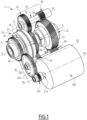
FIG. 1 is an exemplary perspective view of a gearbox assembly for a vehicle axle, according to an example, shown coupled to an electric motor. -
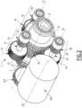
FIG. 2 is an exemplary perspective view of a gearbox assembly for a vehicle axle, according to another example, shown coupled to an electric motor and seen from a rear view. -
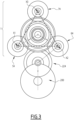
FIG. 3 is a schematic plan view of the components illustrated inFIG. 2 . -
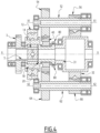
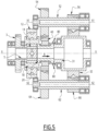
FIG. 4 ,5 and6 are side cross-sections schematically illustrating the gearbox assembly for a vehicle axle ofFIG. 1 or ofFIG 2 , in three different positions; -
FIG. 7 is an exploded perspective view schematically illustrating components of a vehicle axle including a powertrain assembly, according to an example; -
FIG. 8 . is a perspective view of a portion of a vehicle axle with a powertrain assembly assembled, according to a possible example. - The detailed description set forth below provides information and examples of the disclosed technology with sufficient detail to enable those skilled in the art to practice the disclosure.
- In general, vehicle axles, and in particular electric or E-axle of vehicles, may be somehow difficult and cumbersome to be installed and their structure and configuration may not be flexible enough to be applied to different vehicles.
- To this regard, and as it will become more evident hereinafter, the present disclosure provides a gearbox assembly for a vehicle axle, as well as a powertrain assembly comprising such gearbox assembly, comprising: a planetary gear system suitable to receive power from a motor, in particular an electric motor, associated to and configured for driving the wheels attached at the ends of the vehicle axle, a differential positioned adjacent to the planet carrier of the planetary gear system; a free wheeling gear located concentrically to an output shaft of the planet carrier; a plurality of countershaft assemblies configured for coupling with the free wheeling gear and an output gear of the differential; and a clutch which is configured to be shifted between a first position where it couples the planet carrier with the free wheeling gear, and a second position where it couples the planet carrier with the differential.
- The gearbox assembly and the powertrain assembly according to the disclosure may thus result in obtaining a multi-speed output of the differential, may have a robust and compact structure, and may also have a simplified and modular configuration that may be applied to different vehicles.
-
FIG. 1 andFIG. 2 illustrate two examples of a gearbox assembly according to the disclosure, indicated by theoverall reference number 1. - The
gearbox assembly 1 is suitable to be installed along a vehicle axle, in particular an E-axle, an example of which is shown inFIG. 7 and (partly) inFig. 8 , and therein indicated by theoverall reference 100. - The
vehicle axle 100 extends along a longitudinal axis, indicated in the figures by the capital letter X, around which the wheels (not illustrated) attached to the opposite ends 101 and 102 (seefigure 7 ) of theaxle 100, can be rotated. - The
gearbox assembly 1 is shown in the figures coupled to amotor 200 which is suitable to provide thegearbox assembly 1 with the power/torque needed for rotating the wheels. - In particular, the
gearbox assembly 1 comprises at least: - a planetary gear system, indicated in
FIG. 1 andFIG.2 by theoverall reference number 10, which is for example installed along thevehicle axle 100; - a differential 30;
- a
free wheeling gear 40; - a plurality of
countershaft assemblies - a clutch, schematically represented in
FIG. 4 to 6 by thereference number 80. - The
planetary gear system 10 comprises for example aring gear 12 which is suitable to be connected to a housing, e.g. a housing of the assembly illustrated inFIG. 8 and there indicated by thereference number 2, asun gear 14, aplanet 16 comprising one or more planet gears, aplanet carrier 18 which comprises an output member, indicated inFIG. 4 to 6 by thereference number 20, for example a shaft, and can be driven for example by thesun gear 14. - The differential 30 is positioned along the rotation axis X and comprises a
shaft member 31 which is positioned along theaxle 100, rotating around the rotation axis X, and has a first end which is adjacent to and faces theoutput member 20 of theplanet carrier 18, and anoutput gear 32 which is positioned, on theshaft member 31, concentrically to the rotation axis X, for instance at a second end of theshaft member 31 opposite to said first end. - In one possible example, the
free wheeling gear 40 is located around and concentrically to theoutput member 20 of theplanet carrier 18. - Each of the plurality of countershafts assemblies comprises a respective countershaft which is positioned rotating about an axis substantially parallel to the rotation axis X, and two respective countershaft gears which are mounted on the corresponding countershaft, spaced apart from each other, and are configured to engage one with the
free wheeling gear 40 and the other with theoutput gear 32 of the differential 30, respectively. - The clutch 80 is shown in
FIG. 4 in a neutral position and is configured to be operated between a first position, schematically illustrated infigure 6 , where it couples theplanet carrier 18, and in particular itsoutput member 20, with thefree wheeling gear 40, and a second position, schematically illustrated infigure 5 , where it couples theplanet carrier 18, and in particular itsoutput member 20, directly with the differential 30, and in particular with theshaft member 31. - In one possible example, the clutch 80 is positioned, along the axis X, between the
planet carrier 18, and in particular itsoutput member 20, and the differential 30, in particular the first end portion of theshaft member 31, and is configured to be operated to shift, along the rotation axis X, between said first and second positions. - In this way, when the clutch 80 is operated, for instance shifting in a first direction (see arrow A in
FIG.6 ) along the axis X, it connects theplanet carrier 18 to thefree wheeling gear 40, and thus a low reduction is created that transfers power from themotor 200 to the differential output gear through the multiple countershaft assemblies. - When the clutch 80 is shifted along the
axis 100 in the other direction (see arrow B inFIG. 5 ), a high gear is created since theplanet carrier 18 is coupled directly to the differential 30. - Thus, different speeds, to be transmitted to the wheels, can be usefully obtained at the output of the differential 30.
- In one possible example, the clutch 80 comprises or is constituted by a dog clutch.
- In one possible example, the
free wheeling gear 40 comprises one or more teeth configured to engage with the clutch 80 in said first position and to be disengaged from the clutch 80 in said second position. - In one possible example, as illustrated in
FIG. 1 , the plurality of countershaft assemblies comprises: - a first countershaft assembly, indicated by the
overall reference number 50, which comprises afirst countershaft 52 which is positioned rotating about a first axis X1 parallel to the rotation axis X, afirst countershaft gear 54 and asecond countershaft gear 56 which are mounted on thefirst countershaft 52 spaced apart from each other and are configured to engage with thefree wheeling gear 40 and theoutput gear 32 of the differential 30, respectively; - a second countershaft assembly, indicated by the
overall reference number 60, which comprises asecond countershaft 62 which is positioned, rotating about a second axis X2 parallel to the rotation axis X and to the first axis X1, athird countershaft gear 64 and afourth countershaft gear 66 which are mounted on thesecond countershaft 62 spaced apart from each other and are configured to engage with thefree wheeling gear 40 and theoutput gear 32 of the differential 30, respectively. - In particular, according to one aspect, the
first countershaft 52 is positioned on one side of therotation axis 100 rotating about the first axis X1 parallel to the rotation axis X, and thesecond countershaft 62 is positioned, with respect to the rotation axis X, on a side of the opposite to the one side where thefirst countershaft 52 is positioned, and rotates about the second axis X2. - In practice, the
first countershaft 52 and thesecond countershaft 62 are positioned (seen in a transversal view perpendicular to the rotation axis X) along a virtual circumference having, as its center, the rotation axis X, and where the respective axes X2 and X3 are located diametrically opposite to each other with respect to the rotation axis X, i.e. they are located at the ends of a diameter of such virtual circumference. - In another possible example, as illustrated in
FIG. 2 , in addition to the first andsecond countershaft assemblies overall reference number 70, which comprises: athird countershaft 72 that is positioned rotating about a third axis X3 parallel to the rotation axis X; afifth countershaft gear 74 and asixth countershaft gear 76 which are mounted on thethird countershaft 72, spaced apart from each other, and are configured to engage with thefree wheeling gear 40 and theoutput gear 32, respectively. - According to this example, in one possible aspect the first, second and
third countershafts vehicle axle 100 with their respective rotation axes X1, X2, X3 which are positioned, seen in a transversal plan substantially perpendicular to the rotation axis X, at the vertices of a substantially equilateral triangle, represented infigure 3 with dotted lines. - In one possible example, the
gearbox assembly 1 further comprises a coupling gear, indicated in the figures by thereference number 3, which is mounted along thevehicle axle 100 concentrically to the rotation axis X, and is adapted to be operatively coupled to a motor, such as themotor 200, providing motion/torque to thegearbox assembly 1. - In one possible example, the
coupling gear 3 is connected mechanically to thesun gear 14 via acoupling member 5, such as a spline or any suitable mechanical coupling member. - In practice, the
whole gearbox assembly 1 forms a kind of compact module which can be coupled to any desiredmotor 200 according to the specific applications and needs, thereby forming a powertrain assembly for thevehicle axle 100, as for example illustrated inFIG. 8 . - To this end, the
motor 200, to be associated to thegearbox assembly 1, can be mounted inside a housing, which can be thesame housing 2 accommodating thegearbox assembly 1 and suitably shaped to house also themotor 200, or inside an additional housing coupled to thehousing 2. - As those skilled in the art would easily appreciate, any housing used for accommodating the components of the
gearbox assembly 1 alone, or the whole power train assembly can be realized in any suitable number of pieces. - In a possible example, the
motor 200 is an electric motor having a stator and a rotor, according to solutions well known or readily available to those skilled in the art and therefore herein not described in details. - In particular, in a possible example, as illustrated for instance in the attached figures, the
motor 200 is mounted with its rotor rotating about an axis X4 substantially parallel to the longitudinal axis X of thevehicle axle 100. - In one possible example, illustrated in
FIG. 1 and2 , the powertrain assembly further comprises a gear set 220 configured for mechanically coupling anoutput shaft 210 of themotor 200 itself with thegearbox assembly 1, and in particular with thecoupling gear 3. - In one possible example, the gear set 220 comprises a
first gear 222 suitable to be mounted on theoutput shaft 210 of themotor 200 and asecond gear 224 suitable to be positioned between and to engage with both thefirst gear 222 and thecoupling gear 3 of thegearbox assembly 1. - In this way, a first reduction, which can be suitably pre-selected, can be obtained.
- In a possible example (not illustrated in the figures), the
second gear 224 can be eliminated thefirst gear 222 and thecoupling gear 3 engaging directly with each other. - In another possible example (also not illustrated in the figures) the
motor 200 is an electric motor having a stator and a rotor, wherein themotor 200 is mounted along thevehicle axle 100 with its rotor rotating positioned concentrically to the rotation axis X. - In practice it has been that, according to the various examples disclosed, the presence disclosure provides a
gearbox assembly 1, a powertrain assembly, and a vehicle allowing for optimized packaging, and a simplified, robust, reliable and modular structure. - In particular, the disclosure allows full floating of critical components of the planetary and central gears of the multi-countershaft section of the gearbox.
- The arrangement also allows for very simple bearing layouts, eliminating the need for bearings supporting the planet carrier, thus leading to simplification and improved float/load share.
- In addition to the elimination of the planet carrier support bearings, a simplification of the differential bearings occurs due to the radial force elimination that occurs with a multi-countershaft design. This leads to potentially use simple bearings not requiring shimming or adjustment.
- To sum up, the following examples are given in the present disclosure.
- Example 1: A
gearbox assembly 1 for avehicle axle 100 which extends along a rotation axis X, theassembly 1 comprising at least: - a
planetary gear system 10 which is positioned along thevehicle axle 100 and is suitable to receive power from amotor 200 associated to thevehicle axle 100, theplanetary gear system 10 comprising aring gear 12, asun gear 14, a planet comprising one or more planet gears 16, and aplanet carrier 18 which comprises anoutput member 20; - a differential 30 comprising a
differential shaft 31 which is positioned along therotation axis 100 with a first end adjacent to theplanet carrier 18 and comprises anoutput gear 32 positioned concentrically to the rotation axis X along thedifferential shaft 31; - a
free wheeling gear 40 located concentrically to theoutput member 20 of theplanet carrier 18; - a plurality of
countershaft assemblies - a
countershaft - two countershaft gears 54, 64, 74; 56, 66, 76 which are mounted on the corresponding
countershaft free wheeling gear 40 and the other 56, 66, 76 with theoutput gear 32, respectively; - a clutch 80 which is configured to be operated between a first position where it couples the
planet carrier 18 with thefree wheeling gear 40 and a second position where it couples theplanet carrier 18 directly with the differential 30. - Example 2: The
gearbox assembly 1 of example 1, wherein the plurality of countershaft assemblies comprises: - a
first countershaft assembly 50 comprising afirst countershaft 52 which is positioned rotating about a first axis X1 parallel to the rotation axis X, afirst countershaft gear 54 and asecond countershaft gear 56 which are mounted on thefirst countershaft 52 spaced apart from each other and are configured to engage with thefree wheeling gear 40 and theoutput gear 32, respectively; - a
second countershaft assembly 60 comprising asecond countershaft 62 which is positioned, on a side of thevehicle axis 100 opposite to the one side where thefirst countershaft 52 is positioned, rotating about a second axis X2 parallel to the rotation axis X, athird countershaft gear 64 and afourth countershaft gear 66 which are mounted on thesecond countershaft 62 spaced apart from each other and are configured to engage with thefree wheeling gear 40 and theoutput gear 32, respectively. - Example 3: The gearbox assembly of example 2, wherein said first and
second countershafts - Example 4: The
gearbox assembly 1 of example 1, wherein the plurality of countershaft assemblies comprises: - a
first countershaft assembly 50 comprising afirst countershaft 52 which is positioned rotating about a first axis X1 parallel to the rotation axis X, afirst countershaft gear 54 and asecond countershaft gear 56 which are mounted on thefirst countershaft 52 spaced apart from each other and are configured to engage with thefree wheeling gear 40 and theoutput gear 32, respectively; - a
second countershaft assembly 60 comprising asecond countershaft 62 which is positioned rotating about a second axis X2 parallel to the rotation axis X, athird countershaft gear 64 and afourth countershaft gear 66 which are mounted on thesecond countershaft 62 spaced apart from each other and are configured to engage with thefree wheeling gear 40 and theoutput gear 32, respectively; - a
third countershaft assembly 70 comprising athird countershaft 72 which is positioned rotating about a third axis X3 parallel to the rotation axis X, afifth countershaft gear 74 and asixth countershaft gear 76 which are mounted on thethird countershaft 72 spaced apart from each other and are configured to engage with thefree wheeling gear 40 and theoutput gear 32, respectively. - Example 5: The
gearbox assembly 1 of Example 4, wherein said first, second andthird countershafts - Example 6: The
gearbox assembly 1 according to any one of the previous Examples 1 to 5, wherein the clutch 80 is positioned between theplanet carrier 18 and the differential 30 and is configured to be operated to shift, along the rotation axis X, between said first and second positions. - Example 7: The
gearbox assembly 1 according to one or more of the previous Examples 1 to 6, wherein the clutch 80 comprises or is constituted by a dog clutch. - Example 8: The
gearbox assembly 1 according to one or more of the previous Examples 1 to 7, wherein thefree wheeling gear 40 comprises one or more teeth configured to engage with the clutch 80 in said first position and to be disengaged from the clutch 80 in said second position. - Example 9: The
gearbox assembly 1 according to one or more of the previous Examples 1 to 8, wherein it further comprises acoupling gear 3 which is mounted along thevehicle axle 100 concentrically to the rotation axis X and is adapted to be operatively connected to saidmotor 200. - Example 10: The
gearbox assembly 1 according to one or more of the previous Examples 1 to 9, wherein thecoupling gear 3 is mechanically connected to thesun gear 14 via acoupling member 5. - Example 11: A powertrain assembly for a
vehicle axle 100 which extends along a rotation axis X, the powertrain assembly comprising: - a
gearbox assembly 1 according to one or more of Examples 1 to 10; and - a
motor 200 operatively coupled to thegearbox assembly 1. - Example 12: The powertrain assembly according to Example 11, wherein the
motor 200 is an electric motor having a stator and a rotor, wherein themotor 200 is mounted with its rotor rotating about an axis X4 substantially parallel to the rotation axis X of thevehicle axle 100. - Example 13: The powertrain assembly according to any of Examples 11 and 12, further comprising a gear set 220 configured for mechanically coupling an
output shaft 210 of themotor 200 with thegearbox assembly 1. - Example 14: The powertrain assembly according to Example 13, wherein the
gearbox assembly 1 is according to Example 9 or 10, and wherein the gear set 220 comprises afirst gear 222 suitable to be mounted on theoutput shaft 210 of themotor 200 and asecond gear 224 suitable to be positioned between and to engage with both saidfirst gear 222 and saidcoupling gear 3 of thegearbox assembly 1. - Example 15: The powertrain assembly according to Example 13, wherein the gearbox assembly is according to Examples 9 or 10, and wherein the gear set 220 comprises only one
gear 222 suitable to be mounted on theoutput shaft 210 of themotor 200 and to engage with saidcoupling gear 3 of thegearbox assembly 1. - Example 16: The powertrain assembly according to Example 11, wherein said
motor 200 is an electric motor having a stator and a rotor, wherein themotor 200 is mounted along thevehicle axle 100 with its rotor rotating positioned concentrically to the rotation axis X. - Example 17: The powertrain assembly according to Example 16, wherein the rotor of the
motor 200 is coupled directly with thesun gear 14. - Example 18: A vehicle comprising at least the
gearbox assembly 1 according to one or more of Examples 1 to 10, or a powertrain assembly according to one or more of Examples 11 to 17. - Example 19: The powertrain assembly according to Example 18, wherein the vehicle is a heavy-duty or medium-duty truck.
- The terminology used herein is for the purpose of describing particular aspects only and is not intended to be limiting of the disclosure. As used herein, the singular forms "a," "an," and "the" are intended to include the plural forms as well, unless the context clearly indicates otherwise. As used herein, the term "and/or" includes any and all combinations of one or more of the associated listed items. It will be further understood that the terms "comprises," "comprising," "includes," and/or "including" when used herein specify the presence of stated features, integers, actions, steps, operations, elements, and/or components, but do not preclude the presence or addition of one or more other features, integers, actions, steps, operations, elements, components, and/or groups thereof.
- It will be understood that, although the terms first, second, etc., may be used herein to describe various elements, these elements should not be limited by these terms. These terms are only used to distinguish one element from another. For example, a first element could be termed a second element, and, similarly, a second element could be termed a first element without departing from the scope of the present disclosure.
- Relative terms such as "below" or "above" or "upper" or "lower" or "horizontal" or "vertical" may be used herein to describe a relationship of one element to another element as illustrated in the Figures. It will be understood that these terms and those discussed above are intended to encompass different orientations of the device in addition to the orientation depicted in the Figures. It will be understood that when an element is referred to as being "connected" or "coupled" to another element, it can be directly connected or coupled to the other element, or intervening elements may be present. In contrast, when an element is referred to as being "directly connected" or "directly coupled" to another element, there are no intervening elements present.
- Unless otherwise defined, all terms (including technical and scientific terms) used herein have the same meaning as commonly understood by one of ordinary skill in the art to which this disclosure belongs. It will be further understood that terms used herein should be interpreted as having a meaning consistent with their meaning in the context of this specification and the relevant art and will not be interpreted in an idealized or overly formal sense unless expressly so defined herein.
- In particular, when the term "adapted" or "arranged" or "configured" or "shaped", or "set" or any equivalent or similar term is used herein while referring to any component as a whole, or to any part of a component, or to a combination of components, it has to be understood that it means and encompasses correspondingly either the structure, and/or configuration and/or form and/or positioning of the related component or part thereof, or combinations, such term refers to.
- In addition, when the term "substantial" or "substantially" is used herein, it has to be understood as encompassing an actual variation of plus or minus 5% with respect to an indicated reference value, or axis, or position, and when the terms transversal or transversally are hereby used, they have to be understood as encompassing a direction non-parallel to the reference part(s) or direction(s)/axis they refer to, and perpendicularity has to be considered a specific case of transverse direction.
- Further, in the foregoing description and claims, the numeral ordinals first, second, et cetera..., have been used only for the sake of clarity of description and in no way they should be understood as limiting for whatsoever reason, nor that the order should be necessarily the one described in the illustrated exemplary example(s).
- Finally, it is to be understood that the present disclosure is not limited to the aspects described above and illustrated in the drawings; rather, the skilled person will recognize that many changes and modifications may be made within the scope of the present disclosure and appended claims. In the drawings and specification, there have been disclosed aspects for purposes of illustration only and not for purposes of limitation, the scope of the disclosure being set forth in the following claims.
Claims (20)
- A gearbox assembly (1) for a vehicle axle (100) which extends along a rotation axis (X), the assembly (1) comprising at least:- a planetary gear system (10) which is positioned along the vehicle axle (100) and is suitable to receive power from a motor (200) associated to the vehicle axle (100), the planetary gear system (10) comprising a ring gear (12), a sun gear (14), a planet comprising one or more planet gears (16), and a planet carrier (18) which comprises an output member (20);- a differential (30) comprising a differential shaft (31) which is positioned along the rotation axis (100) with a first end adjacent to the planet carrier (18) and comprises an output gear (32) positioned concentrically to the rotation axis (X) along the differential shaft (31);- a free wheeling gear (40) located concentrically to the output member (20) of the planet carrier (18);- a plurality of countershaft assemblies (50, 60, 70) each comprising:- a countershaft (52, 62, 72) positioned rotating about an axis (X1, X2, X3) parallel to the rotation axis (X);- two countershaft gears (54, 64, 74; 56, 66, 76) which are mounted on the corresponding countershaft (52, 62, 72) spaced apart from each other and are configured to engage one (54, 64, 74) with the free wheeling gear (40) and the other (56, 66, 76) with the output gear (32), respectively;- a clutch (80) which is configured to be operated at least between a first position where it couples the planet carrier (18) with the free wheeling gear (40) and a second position where it couples the planet carrier (18) directly with the differential (30).
- The gearbox assembly (1) according to claim 1, wherein the plurality of countershaft assemblies comprises:- a first countershaft assembly (50) comprising a first countershaft (52) which is positioned rotating about a first axis (X1) parallel to the rotation axis (X), a first countershaft gear (54) and a second countershaft gear (56) which are mounted on the first countershaft (52) spaced apart from each other and are configured to engage with the free wheeling gear (40) and the output gear (32), respectively;- a second countershaft assembly (60) comprising a second countershaft (62) which is positioned, on a side of the vehicle axis (100) opposite to the one side where the first countershaft (52) is positioned, rotating about a second axis (X2) parallel to the rotation axis (X), a third countershaft gear (64) and a fourth countershaft gear (66) which are mounted on the second countershaft (62) spaced apart from each other and are configured to engage with the free wheeling gear (40) and the output gear (32), respectively.
- The gearbox assembly (1) according to claim 2, wherein said first and second countershafts (52, 62) are positioned around the rotation axis (X) along a virtual circumference having, as its center, the rotation axis (X), with their respective first and second rotation axes (X2, X3) that are located diametrically opposite to each other with respect to the rotation axis (X) itself.
- The gearbox assembly (1) according to claim 1, wherein the plurality of countershaft assemblies comprises:- a first countershaft assembly (50) comprising a first countershaft (52) which is positioned rotating about a first axis (X1) parallel to the rotation axis (X), a first countershaft gear (54) and a second countershaft gear (56) which are mounted on the first countershaft (52) spaced apart from each other and are configured to engage with the free wheeling gear (40) and the output gear (32), respectively;- a second countershaft assembly (60) comprising a second countershaft (62) which is positioned rotating about a second axis (X2) parallel to the rotation axis (X), a third countershaft gear (64) and a fourth countershaft gear (66) which are mounted on the second countershaft (62) spaced apart from each other and are configured to engage with the free wheeling gear (40) and the output gear (32), respectively;- a third countershaft assembly (70) comprising a third countershaft (72) which is positioned rotating about a third axis (X3) parallel to the rotation axis (X), a fifth countershaft gear (74) and a sixth countershaft gear (76) which are mounted on the third countershaft (72) spaced apart from each other and are configured to engage with the free wheeling gear (40) and the output gear (32), respectively.
- The gearbox assembly (1) according to claim 4, wherein said first, second and third countershafts (52, 62, 72) are positioned around the rotation axis (X) with their respective rotation axes (X1, X2, X3) positioned at the vertices of a substantially equilateral triangle.
- The gearbox assembly (1) according to one or more of the previous claims, wherein the clutch (80) is positioned between the planet carrier (18) and the differential (30) and is configured to be operated to shift, along the rotation axis (X), between said first and second positions.
- The gearbox assembly (1) according to one or more of the previous claims, wherein the clutch (80) comprises or is constituted by a dog clutch.
- The gearbox assembly (1) according to one or more of the previous claims, wherein the free wheeling gear (40) comprises one or more teeth configured to engage with the clutch (80) in said first position and to be disengaged from the clutch (80) in said second position.
- The gearbox assembly (1) according to one or more of the previous claims, wherein it further comprises a coupling gear (3) which is mounted along the vehicle axle (100) concentrically to the rotation axis (X) and is adapted to be operatively connected to said motor (200).
- The gearbox assembly (1) according to claim 9, wherein the coupling gear (3) is mechanically connected to the sun gear (14) via a coupling member (5).
- A powertrain assembly for a vehicle axle (100) which extends along a rotation axis (X), the powertrain assembly comprising:- a gearbox assembly (1) according to one or more of the previous claims; and- a motor (200) operatively coupled to the gearbox assembly (1).
- The powertrain assembly according to claim 11, wherein the motor (200) is an electric motor having a stator and a rotor, wherein the motor (200) is mounted with its rotor rotating about an axis (X4) substantially parallel to the rotation axis (X) of the vehicle axle (100).
- The powertrain assembly according to any of claims 11 and 12, further comprising a gear set (220) configured for mechanically coupling an output shaft (210) of the motor (200) with the gearbox assembly (1).
- The powertrain assembly according to claim 13, wherein the gearbox assembly is according to claim 9 or 10, and wherein the gear set (220) comprises a first gear (222) suitable to be mounted on the output shaft (210) of the motor (200) and a second gear (224) suitable to be positioned between and to engage with both said first gear (222) and said coupling gear (3) of the gearbox assembly (1).
- The powertrain assembly according to claim 13, wherein the gearbox assembly is according to claim 9 or 10, and wherein the gear set (220) comprises only a first gear (222) suitable to be mounted on the output shaft (210) of the motor (200) and to engage with said coupling gear (3) of the gearbox assembly (1).
- The powertrain assembly according to claim 11, wherein said motor (200) is an electric motor having a stator and a rotor, wherein the motor (200) is mounted along the vehicle axle (100) with its rotor rotating positioned concentrically to the rotation axis (X).
- The powertrain assembly according to claim 16, wherein the rotor of said motor (200) is coupled directly with the sun gear (14).
- A vehicle comprising at least the gearbox assembly (1) according to one or more of claims 1 to 10 or a powertrain assembly according to one or more of claims 11 to 17.
- The vehicle according to claim 18, wherein the vehicle is a heavy-duty or medium-duty vehicle.
- The vehicle according to claim 18 or 19, wherein the vehicle is a heavy-duty or medium-duty truck.
Priority Applications (3)
| Application Number | Priority Date | Filing Date | Title |
|---|---|---|---|
| EP23179029.6A EP4477920A1 (en) | 2023-06-13 | 2023-06-13 | Gearbox assembly and power train assembly for a vehicle axle, and related vehicle |
| US18/738,291 US20240416746A1 (en) | 2023-06-13 | 2024-06-10 | Gearbox assembly and power train assembly for a vehicle axle, and related vehicle |
| CN202410744149.4A CN119123007A (en) | 2023-06-13 | 2024-06-11 | Gearbox assembly and powertrain assembly for vehicle axle and related vehicle |
Applications Claiming Priority (1)
| Application Number | Priority Date | Filing Date | Title |
|---|---|---|---|
| EP23179029.6A EP4477920A1 (en) | 2023-06-13 | 2023-06-13 | Gearbox assembly and power train assembly for a vehicle axle, and related vehicle |
Publications (1)
| Publication Number | Publication Date |
|---|---|
| EP4477920A1 true EP4477920A1 (en) | 2024-12-18 |
Family
ID=86764662
Family Applications (1)
| Application Number | Title | Priority Date | Filing Date |
|---|---|---|---|
| EP23179029.6A Pending EP4477920A1 (en) | 2023-06-13 | 2023-06-13 | Gearbox assembly and power train assembly for a vehicle axle, and related vehicle |
Country Status (3)
| Country | Link |
|---|---|
| US (1) | US20240416746A1 (en) |
| EP (1) | EP4477920A1 (en) |
| CN (1) | CN119123007A (en) |
Citations (9)
| Publication number | Priority date | Publication date | Assignee | Title |
|---|---|---|---|---|
| US2152771A (en) * | 1936-03-16 | 1939-04-04 | Clark Equipment Co | Two-speed rear axle |
| DE102009030978A1 (en) * | 2008-07-21 | 2010-01-28 | Luk Lamellen Und Kupplungsbau Beteiligungs Kg | Rotation direction reversal mechanism for crank-continuously variable transmission gearbox of drive device, has input shaft, which is connected with output shaft of crank-continuously variable transmission gearbox |
| DE102013204227A1 (en) * | 2013-03-12 | 2014-09-18 | Zf Friedrichshafen Ag | Drive train for a vehicle and method for performing a load change |
| CN205260777U (en) * | 2015-10-27 | 2016-05-25 | 同济大学 | Dead axle formula derailleur for hybrid vehicle |
| CN106382349A (en) * | 2016-12-07 | 2017-02-08 | 天津天海同步集团有限公司 | Double-motor compact transmission without power failure |
| DE102019214512A1 (en) * | 2019-09-24 | 2021-03-25 | Zf Friedrichshafen Ag | Drive train for a motor vehicle |
| EP3798466A1 (en) * | 2019-09-26 | 2021-03-31 | ArvinMeritor Technology, LLC | Axle assembly having gear mechanisms |
| US20220045574A1 (en) * | 2020-08-06 | 2022-02-10 | Jtekt Corporation | Driving device |
| EP4190609A1 (en) * | 2021-12-02 | 2023-06-07 | Nio Technology (Anhui) Co., Ltd | Electric drive assembly for electric vehicle, and electric vehicle |
Family Cites Families (7)
| Publication number | Priority date | Publication date | Assignee | Title |
|---|---|---|---|---|
| DE102017201894A1 (en) * | 2017-02-07 | 2018-08-09 | Zf Friedrichshafen Ag | Construction of a transmission for a hybrid vehicle |
| DE102018203458B4 (en) * | 2018-03-07 | 2019-10-17 | Audi Ag | Drive device for an electrically operated vehicle |
| GB2590843B (en) * | 2018-08-16 | 2022-12-07 | Allison Transm Inc | Electric axle assembly |
| DE102018221612A1 (en) * | 2018-12-13 | 2020-06-18 | Zf Friedrichshafen Ag | Rigid axle driven by an electric motor for vehicles, in particular commercial vehicles, with electric motors near the wheel and offset gears |
| US11015689B2 (en) * | 2019-02-18 | 2021-05-25 | Ford Global Technologies, Llc | Multi-speed electric machine gearbox with low drive ratio |
| DE102021005711A1 (en) * | 2021-11-18 | 2023-05-25 | Daimler Truck AG | Electric drive system for a motor vehicle, in particular for a motor vehicle |
| US11828353B1 (en) * | 2022-09-14 | 2023-11-28 | Arvinmeritor Technology, Llc | Axle assembly having a planetary gear set |
-
2023
- 2023-06-13 EP EP23179029.6A patent/EP4477920A1/en active Pending
-
2024
- 2024-06-10 US US18/738,291 patent/US20240416746A1/en active Pending
- 2024-06-11 CN CN202410744149.4A patent/CN119123007A/en active Pending
Patent Citations (9)
| Publication number | Priority date | Publication date | Assignee | Title |
|---|---|---|---|---|
| US2152771A (en) * | 1936-03-16 | 1939-04-04 | Clark Equipment Co | Two-speed rear axle |
| DE102009030978A1 (en) * | 2008-07-21 | 2010-01-28 | Luk Lamellen Und Kupplungsbau Beteiligungs Kg | Rotation direction reversal mechanism for crank-continuously variable transmission gearbox of drive device, has input shaft, which is connected with output shaft of crank-continuously variable transmission gearbox |
| DE102013204227A1 (en) * | 2013-03-12 | 2014-09-18 | Zf Friedrichshafen Ag | Drive train for a vehicle and method for performing a load change |
| CN205260777U (en) * | 2015-10-27 | 2016-05-25 | 同济大学 | Dead axle formula derailleur for hybrid vehicle |
| CN106382349A (en) * | 2016-12-07 | 2017-02-08 | 天津天海同步集团有限公司 | Double-motor compact transmission without power failure |
| DE102019214512A1 (en) * | 2019-09-24 | 2021-03-25 | Zf Friedrichshafen Ag | Drive train for a motor vehicle |
| EP3798466A1 (en) * | 2019-09-26 | 2021-03-31 | ArvinMeritor Technology, LLC | Axle assembly having gear mechanisms |
| US20220045574A1 (en) * | 2020-08-06 | 2022-02-10 | Jtekt Corporation | Driving device |
| EP4190609A1 (en) * | 2021-12-02 | 2023-06-07 | Nio Technology (Anhui) Co., Ltd | Electric drive assembly for electric vehicle, and electric vehicle |
Also Published As
| Publication number | Publication date |
|---|---|
| CN119123007A (en) | 2024-12-13 |
| US20240416746A1 (en) | 2024-12-19 |
Similar Documents
| Publication | Publication Date | Title |
|---|---|---|
| US11975606B2 (en) | Drive axle system having multiple electric motors | |
| EP4198343A1 (en) | Axle assembly having a gear reduction module with countershaft gear sets | |
| EP3805604A1 (en) | Axle assembly having a multi-speed countershaft transmission | |
| CN112696475B (en) | Axle assembly having a multi-speed transmission and a reduction gear set | |
| US12157335B2 (en) | Axle assembly | |
| US6080077A (en) | Planetary gear drive train | |
| JP2006521517A (en) | 4-branch differential transmission system | |
| US20240270067A1 (en) | Vehicle driving assembly and vehicle | |
| CN113059960A (en) | Axle assembly with rotor bearing assembly | |
| CN104421380B (en) | Method of making a bevel gear system | |
| US20240017602A1 (en) | Compact e-axle assembly | |
| US11841066B2 (en) | Axle assembly having a gear reduction module with multiple gear sets | |
| EP4338994A1 (en) | Axle assembly having a planetary gear set | |
| US20240416746A1 (en) | Gearbox assembly and power train assembly for a vehicle axle, and related vehicle | |
| EP4238802A1 (en) | Improved torque distributor system among axles of a heavy vehicle | |
| US12071004B2 (en) | Transmission assembly | |
| CN221075114U (en) | Electric drive axle | |
| EP4729805A1 (en) | Torque distribution gearing for a vehicle | |
| EP4700256A1 (en) | A transmissison for a vehicle | |
| WO2024046659A1 (en) | Gearbox for vehicle electric axle and integrated electric axle | |
| CN121941863A (en) | Rotary gear transmission devices and related systems, components and methods |
Legal Events
| Date | Code | Title | Description |
|---|---|---|---|
| PUAI | Public reference made under article 153(3) epc to a published international application that has entered the european phase |
Free format text: ORIGINAL CODE: 0009012 |
|
| STAA | Information on the status of an ep patent application or granted ep patent |
Free format text: STATUS: THE APPLICATION HAS BEEN PUBLISHED |
|
| AK | Designated contracting states |
Kind code of ref document: A1 Designated state(s): AL AT BE BG CH CY CZ DE DK EE ES FI FR GB GR HR HU IE IS IT LI LT LU LV MC ME MK MT NL NO PL PT RO RS SE SI SK SM TR |
|
| STAA | Information on the status of an ep patent application or granted ep patent |
Free format text: STATUS: REQUEST FOR EXAMINATION WAS MADE |
|
| 17P | Request for examination filed |
Effective date: 20250520 |
|
| GRAP | Despatch of communication of intention to grant a patent |
Free format text: ORIGINAL CODE: EPIDOSNIGR1 |
|
| STAA | Information on the status of an ep patent application or granted ep patent |
Free format text: STATUS: GRANT OF PATENT IS INTENDED |
|
| INTG | Intention to grant announced |
Effective date: 20260129 |
|
| GRAS | Grant fee paid |
Free format text: ORIGINAL CODE: EPIDOSNIGR3 |
|
| GRAA | (expected) grant |
Free format text: ORIGINAL CODE: 0009210 |
|
| STAA | Information on the status of an ep patent application or granted ep patent |
Free format text: STATUS: THE PATENT HAS BEEN GRANTED |