EP4477890A1 - Fan speed control method and device - Google Patents
Fan speed control method and device Download PDFInfo
- Publication number
- EP4477890A1 EP4477890A1 EP23206709.0A EP23206709A EP4477890A1 EP 4477890 A1 EP4477890 A1 EP 4477890A1 EP 23206709 A EP23206709 A EP 23206709A EP 4477890 A1 EP4477890 A1 EP 4477890A1
- Authority
- EP
- European Patent Office
- Prior art keywords
- parameter
- fan
- operating parameter
- operating
- load
- Prior art date
- Legal status (The legal status is an assumption and is not a legal conclusion. Google has not performed a legal analysis and makes no representation as to the accuracy of the status listed.)
- Pending
Links
Images




Classifications
-
- F—MECHANICAL ENGINEERING; LIGHTING; HEATING; WEAPONS; BLASTING
- F04—POSITIVE - DISPLACEMENT MACHINES FOR LIQUIDS; PUMPS FOR LIQUIDS OR ELASTIC FLUIDS
- F04D—NON-POSITIVE-DISPLACEMENT PUMPS
- F04D27/00—Control, e.g. regulation, of pumps, pumping installations or pumping systems specially adapted for elastic fluids
- F04D27/004—Control, e.g. regulation, of pumps, pumping installations or pumping systems specially adapted for elastic fluids by varying driving speed
-
- F—MECHANICAL ENGINEERING; LIGHTING; HEATING; WEAPONS; BLASTING
- F04—POSITIVE - DISPLACEMENT MACHINES FOR LIQUIDS; PUMPS FOR LIQUIDS OR ELASTIC FLUIDS
- F04D—NON-POSITIVE-DISPLACEMENT PUMPS
- F04D29/00—Details, component parts, or accessories
- F04D29/66—Combating cavitation, whirls, noise, vibration or the like; Balancing
- F04D29/661—Combating cavitation, whirls, noise, vibration or the like; Balancing especially adapted for elastic fluid pumps
- F04D29/663—Sound attenuation
-
- G—PHYSICS
- G06—COMPUTING OR CALCULATING; COUNTING
- G06F—ELECTRIC DIGITAL DATA PROCESSING
- G06F1/00—Details not covered by groups G06F3/00 - G06F13/00 and G06F21/00
- G06F1/16—Constructional details or arrangements
- G06F1/20—Cooling means
-
- G—PHYSICS
- G06—COMPUTING OR CALCULATING; COUNTING
- G06F—ELECTRIC DIGITAL DATA PROCESSING
- G06F1/00—Details not covered by groups G06F3/00 - G06F13/00 and G06F21/00
- G06F1/16—Constructional details or arrangements
- G06F1/20—Cooling means
- G06F1/206—Cooling means comprising thermal management
Definitions
- This disclosure relates to a fan speed control method and device.
- prior art includes acquiring current tachometers of multiple heat sources of the electronic device, determining the corresponding rotational speed of the fan according to the selected current tachometers, and setting the fan corresponding to the heat sources as the rotational speed.
- this disclosure provides a fan speed control method and device.
- a fan speed control method performed by a controller, includes: obtaining a first load parameter associated with a main board; obtaining a second load parameter associated with an expansion board; determining a greater one of the first load parameter and the second load parameter; and controlling a fan according to the greater one.
- a fan speed control device includes: a main board, an expansion slot, a fan and a controller.
- the expansion slot is disposed on the main board and configured to electrically connect an expansion board.
- the fan is disposed on the expansion board.
- the controller is disposed on the main board, electrically connected to the expansion slot, and configured to perform: obtaining a first load parameter associated with the main board; obtaining a second load parameter associated with the expansion board; determining a greater one of the first load parameter and the second load parameter; and controlling a fan according to the greater one.
- the fan speed control method and device may allow the speed of the fan to not fluctuates rapidly by the operation condition of the expansion board when cooling is performed using the fan. Accordingly, the fan speed may be steadily controlled, thereby easing the noise caused by the operating fan.
- the following description of the fan speed control method of one or more embodiments may be performed by a controller, and may be performed periodically or non-periodically after a fan speed control device is activated. Further, after the fan speed control device is activated, the controller may also wait for a preset period of time to perform the fan speed control method, wherein said preset period of time is, for example, 30 seconds, 40 seconds or 1 minute, the present disclosure is not limited thereto.
- the "speed" described in the present disclosure means the rotation speed of the fan.
- FIG. 1 is a block diagram illustrating a fan speed control device and an expansion board according to an embodiment of the present disclosure.
- the fan speed control device 1 includes a main board 10, a controller 11, a system fan 12 and an expansion slot 13.
- the fan speed control device 1 may be disposed on a computer host, that is, the fan speed control device 1 may be a part of a computer host.
- the controller 11, the system fan 12 and the expansion slot 13 are disposed on the main board 10.
- the controller 11 is electrically connected to the system fan 12 and the expansion slot 13.
- the main board 10 may also be referred to as a motherboard with one or more processors disposed thereon.
- the controller 11 may include one or more controllers, said controller is, for example, an embedded controller (EC), a microcontroller, a programmable logic controller or any other controller with signal processing function.
- the system fan 12 may be configured to dissipate heat from one or more elements on the main board 10, and is controlled by the controller 11.
- the system fan 12 is disposed on the main board 10 and corresponds to the expansion slot 13. In other words, in addition to cooling elements on the main board 10, the system fan 12 may further be used for cooling element(s) (for example, an the expansion board A1) connected to the expansion slot 13.
- the main board 10, the controller 11, the system fan 12 and the expansion slot 13 may be disposed on the same computer.
- the expansion slot 13 may include one or more of a peripheral component interconnect express (PCIE), a universal serial bus (USB) and a high definition multimedia interface (HDMI), the present disclosure is not limited thereto.
- PCIE peripheral component interconnect express
- USB universal serial bus
- HDMI high definition multimedia interface
- the expansion slot 13 is disposed on the main board 10 and configured to electrically connect the expansion board A1, wherein another processor and another fan (for example, the expansion fan described below) may be disposed on the expansion board A1.
- the expansion board A1 may be a board for carrying (or mounting) and connecting external processor.
- FIG. 2 is a flowchart illustrating a fan speed control method according to an embodiment of the present disclosure.
- the fan speed control method is performed by the controller 11, and as shown in FIG. 2 , includes: step S101: obtaining a first load parameter associated with a main board; step S103: obtaining a second load parameter associated with an expansion board; step S105: determining a greater one of the first load parameter and the second load parameter; and step S107: controlling a fan according to the greater one.
- step S101 may be performed before or after step S103, step S101 may also be performed with step S103 at the same time.
- the controller 11 obtains the first load parameter associated with operation condition of the main board 10.
- the first load parameter may be a parameter reflecting the operation condition corresponding to the main board 10, and may include a temperature of the main board 10, a temperature of a processor disposed on the main board 10, fan speed or duty cycle of the system fan 12, a processor usage of the processor disposed on the main board 10 or wattage consumption of the main board 10 etc.
- the controller 11 obtains the second load parameter associated with the operation condition of the expansion board A1.
- the controller 11 obtains the second load parameter of the expansion board A1 through the expansion slot 13.
- the second load parameter may be a parameter reflecting the operation condition corresponding to the expansion slot 13, and may include a temperature of a processor disposed on the expansion board A1, fan speed or duty cycle corresponding to the temperature of the processor, fan speed or duty cycle of another fan on the expansion board A1, a processor usage of the processor or wattage consumption of the expansion board A1 etc.
- step S105 the controller 11 determines a greater one of the first load parameter and the second load parameter.
- the first load parameter and the second load parameter used for comparison in step S105 are the same type of parameters. For example, in step S105, if the first load parameter is the temperature of the main board 10, the second load parameter is the temperature of the processor on the expansion board A1; if the first load parameter is the processor usage of the processor disposed on the main board 10, the second load parameter is the processor usage of the processor disposed on the expansion board A1.
- step S107 the controller 11 controls the speed of the system fan 12 according to greater one of the two load parameters, or controls the speed of said another fan on the expansion board A1 according to the greater one of the two load parameters.
- the controller 11 controls said another fan on the expansion board A1 or the system fan 12 according to the fan speed or duty cycle corresponding to the greater load parameter.
- the controller 11 may control said another fan on the expansion board A1 or the system fan 12 based on the fan speed corresponding to the temperature of the processor disposed on the expansion board A1.
- the controller 11 may control said another fan on the expansion board A1 or the system fan 12 based on the fan speed corresponding to the temperature of the processor disposed on the expansion board A1.
- the controller 11 may control said another fan on the expansion board A1 or the system fan 12 according to an operating parameter-fan parameter corresponding function (referred to as "the corresponding function" hereinafter) corresponding to said greater one.
- the first load parameter and the second load parameter may be fan speeds
- the operating parameter may be temperatures.
- the controller 11 may select the corresponding function corresponding to the main board 10 according to the first load parameter, read the selected corresponding function according to the temperature of the main board 10 to determine a corresponding fan parameter, and control said another fan on the expansion board A1 or the system fan 12 according to the fan parameter.
- the operating parameter corresponding to the first load parameter may be the temperature of the main board 10, the processor usage of the processor disposed on the main board 10 or the wattage consumption of the main board 10.
- the operating parameter corresponding to the second load parameter may be the temperature of the processor disposed on the expansion board A1, the processor usage of the processor disposed on the expansion board A1 or the wattage consumption of the expansion board A1.
- the main board 10 and the expansion board A1 may each has a corresponding function, which records corresponding relationship between a plurality of operating parameters and a plurality of fan parameters.
- the corresponding function is, for example, table 1 and table 2 as shown below, and may be stored in the controller 11, wherein the numbers of pieces of data of the operating parameter in the fan parameter table 1 and table 2 are only examples.
- Table 1 Corresponding function of the main board first operating parameter first fan parameter second operating parameter second fan parameter Table 2
- the controller 11 may refer to table 1 or table 2, to select the corresponding function according to the greater load parameter, determine the fan parameter according to the greater load parameter and the selected corresponding function, and control said another fan on the expansion board A1 or the system fan 12 according to the fan parameter.
- table 1 and table 2 for example, assuming that the operating parameter that the main board 10 corresponds to is the temperature of the main board 10, the operating parameter that the expansion board A1 corresponds to is the temperature of the processor disposed on the expansion board A1, and the second load parameter is greater than the first load parameter, then in step S107, the controller 11 may refer to table 2 to determine that the operating parameter (temperature) that the expansion board A1 corresponds to belongs to the third operating parameter or the fourth operating parameter.
- the controller 11 controls said another fan on the expansion board A1 or the system fan 12 according to the third fan parameter; if the operating parameter (temperature) that the expansion board A1 corresponds to belongs to the fourth operating parameter, the controller 11 controls said another fan on the expansion board A1 or the system fan 12 according to the fourth fan parameter.
- the first operating parameter to the fourth operating parameter shown in table 1 and table 2 may each be a value or a range.
- the operating parameter that the expansion board A1 corresponds to belonging to the third operating parameter may mean that the operating parameter that the expansion board A1 corresponds to equals to the third operating parameter, or the operating parameter falls within the numerical range of the third operating parameter.
- the first operating parameter to the fourth operating parameter each is a numerical range
- an upper limit of the first operating parameter of the corresponding function of the main board 10 may be a lower limit of the second operating parameter
- the third operating parameter of the corresponding function of the expansion board A1 may be a lower limit of the fourth operating parameter.
- the first operating parameter may not overlap, partially overlap or completely overlap the third operating parameter
- the second operating parameter may not overlap, partially overlap or completely overlap the fourth operating parameter.
- rapid increase and decrease of the fan speed caused by the operation condition of the expansion board may be avoided when cooling is performed using the fan. Accordingly, the fan speed may be steadily controlled, thereby reducing the noise generated when controlling the fan.
- FIG. 3 is a block diagram illustrating a fan speed control device and an expansion board according to another embodiment of the present disclosure.
- the fan speed control device 2 according to another embodiment of the present disclosure includes a main board 20, a controller 21, a system fan 22, an expansion slot 23 and a first processor 24, wherein the expansion slot 23 is electrically connected to the expansion board A1.
- the fan speed control device 2 may be disposed on a computer host, that is, the fan speed control device 2 may be a part of a computer host.
- the implementation of the main board 20, the controller 21, the system fan 22 and the expansion slot 23 may be the same as the main board 10, the controller 11, the system fan 12 and the expansion slot 13 of FIG. 1 , their details are not repeated herein.
- the expansion board A1 includes a second processor A11.
- the first processor 24 may be a central processing unit (CPU)
- the second processor A11 may be a graphic processing unit (GPU).
- FIG. 4 is a flowchart illustrating a method of controlling a fan according to an embodiment of the present disclosure.
- the fan speed control method shown in FIG. 4 is performed by the controller 21, and as shown in FIG. 4 , in addition to step S101 and step S103 shown in FIG.
- the method further includes: step S201: determining a relationship between the first load parameter and the second load parameter; if the second load parameter is lower than the first load parameter, performing step S203: controlling the fan according to a first operating parameter-fan parameter corresponding function and an operating parameter of the first processor; if the second load parameter equals to the first load parameter, performing step S205: controlling the fan according to the first operating parameter-fan parameter corresponding function and the operating parameter of the first processor or controlling the fan according to a second operating parameter-fan parameter corresponding function and an operating parameter of the second processor; and if the second load parameter is greater than the first load parameter, performing step S207: controlling the fan according to the second operating parameter-fan parameter corresponding function and the operating parameter of the second processor.
- Step S201 shown in FIG. 4 may be regarded as a detail flowchart of an embodiment of step S105 of FIG. 2
- steps S203, S205 and S207 shown in FIG. 4 may be regarded as a detail flowchart of an embodiment of step S107 of FIG. 2 .
- the first load parameter is the load parameter of the first processor 24 disposed on the main board 20
- the second load parameter is the load parameter of the second processor A11 disposed on the expansion board A1.
- examples of the first operating parameter-fan parameter corresponding function (referred to as “the first corresponding function” hereinafter) and the second operating parameter-fan parameter corresponding function (referred to as “the second corresponding function” hereinafter) are respectively shown in table 3 and table 4 below, and the first corresponding function and the second corresponding function may be stored in the controller 21.
- the first candidate operating parameter to the fourth candidate operating parameter shown in table 3 and table 4 may each be a numerical range, and an upper limit of the first candidate operating parameter of the first corresponding function may be a lower limit the second candidate operating parameter, and an upper limit of the third candidate operating parameter of the second corresponding function may be a lower limit of the fourth candidate operating parameter.
- Table 3 the first corresponding function first candidate operating parameter first candidate fan parameter second candidate operating parameter second candidate fan parameter
- Table 4 the second corresponding function third candidate operating parameter third candidate fan parameter fourth candidate operating parameter fourth candidate fan parameter
- the first candidate operating parameter and the second candidate operating parameter may be the same as the operating parameter corresponding to the first load parameter as described above.
- each of the first candidate operating parameter and the second candidate operating parameter may be temperature of the main board 20, processor usage of the first processor 24 or wattage consumption of the main board 20.
- the third candidate operating parameter and the fourth candidate operating parameter may be the same as the operating parameter corresponding to the second load parameter as described above.
- each of the third candidate operating parameter and the fourth candidate operating parameter may be temperature of the second processor A11, processor usage of the second processor A11 or wattage consumption of the expansion board A1.
- step S201 the controller 21 determines the numerical relationship between the first load parameter and the second load parameter for the controller 21 to perform subsequent steps according to the determination result.
- step S203 the controller 21 looks up the first corresponding function for the candidate operating parameter that the main board 20 corresponds to according to the operating parameter of the first processor 24, and controls said another fan on the expansion board A1 or the system fan 22 according to the candidate fan parameter that the candidate operating parameter corresponds to.
- step S205 the controller 21 looks up the first corresponding function for the candidate operating parameter that the main board 20 corresponds to according to the operating parameter of the first processor 24, and controls said another fan on the expansion board A1 or the system fan 22 according to the candidate fan parameter that the candidate operating parameter corresponds to; or, the controller 21 looks up the second corresponding function for the candidate operating parameter t according to the operating parameter of the second processor A11, and controls said another fan on the expansion board A1 or the system fan 22 according to the candidate fan parameter that the candidate operating parameter corresponds to.
- the controller 21 may control said another fan on the expansion board A1 or the system fan 22 according to the operating parameter of the first processor 24 and the first corresponding function, so that the speed of said another fan on the expansion board A1 or the system fan 22 may be more steady.
- step S207 the controller 21 looks up the second corresponding function for the candidate operating parameter corresponding to the expansion board A1 according to the operating parameter of the second processor A11, and controls said another fan on the expansion board A1 or the system fan 22 according to the candidate fan parameter that the candidate operating parameter corresponds to.
- the method of looking up the first corresponding function for the candidate operating parameter , and controlling said another fan on the expansion board A1 or the system fan 22 according to the candidate fan parameter that the candidate operating parameter corresponds to may include: the controller 21 determining which one of the candidate operating parameters in the first corresponding function equals to the operating parameter, thereby controlling said another fan on the expansion board A1 or the system fan 22 according to the candidate fan parameter that the candidate operating parameter corresponds to; or, the candidate operating parameter being a numerical range, and the controller 21 determining which one of the candidate operating parameters in the first corresponding function that the first corresponding function falls within, thereby controlling said another fan on the expansion board A1 or the system fan 22 according to the candidate fan parameter that the candidate operating parameter corresponds to.
- table 1 may be the same as table 3
- table 2 may be the same as table 4.
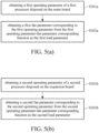
- FIG. 5(a) is a flowchart illustrating a method of obtaining a first load parameter according to an embodiment of the present disclosure. Steps shown in FIG. 5(a) may be regarded as a detail flowchart of an embodiment of step S101 of FIG. 2 .
- the method of obtaining the first load parameter includes: step S301a: obtaining a first operating parameter of a first processor disposed on the main board; and step S303a: obtaining a first fan parameter corresponding to the first operating parameter from the first operating parameter-fan parameter corresponding function as the first load parameter.
- step S301a the controller 21 obtains the first operating parameter of the first processor 24.
- step S303a the controller 21 obtains the first fan parameter corresponding to the first operating parameter according to the first corresponding function as shown in table 3, and uses the obtained first fan parameter as the first load parameter.
- the controller 21 may look for the candidate operating parameter that the first operating parameter belongs to by looking up the first corresponding function (table 3), and uses the candidate fan parameter corresponding to the candidate operating parameter as the first load parameter.
- the method of the controller 21 looking for the first operating parameter in the first corresponding function is as described above, and is not repeated herein.
- FIG. 5(b) is a flowchart illustrating a method of obtaining a second load parameter according to an embodiment of the present disclosure. Steps shown in FIG. 5(b) may be regarded as a detail flowchart of an embodiment of step S103 of FIG. 2 .
- the method of obtaining the second load parameter includes: step S301b: obtaining a second operating parameter of a second processor disposed on the expansion board; and step S303b: obtaining a second fan parameter corresponding to the second operating parameter from the second operating parameter-fan parameter corresponding function as the second load parameter.
- step S301b the controller 21 obtains the second operating parameter of the second processor A11.
- step S303b the controller 21 obtains the second fan parameter corresponding to the second operating parameter according to the second corresponding function as shown in table 4, and uses the obtained second fan parameter as the second load parameter.
- the controller 21 may look for the candidate operating parameter that the second operating parameter belongs to by looking up the second corresponding function (table 4), and uses the candidate fan parameter corresponding to the candidate operating parameter as the second load parameter.
- the method of the controller 21 looking for the second operating parameter in the second corresponding function is as described above, and is not repeated herein.
- the physical unit of the first fan parameter and the physical unit of the second fan parameter are duty cycle of pulse-width modulation (PWM), or revolutions per minute (RPM) of the system fan 22.
- the first corresponding function describes a first corresponding policy of the first fan parameter corresponding to the first operating parameter, or a first numerical lookup table (for example, table 3) listing the first fan parameter corresponding to the first operating parameter, or a first function graph presenting the first fan parameter corresponding to the first operating parameter.
- the second corresponding function describes a second corresponding policy of the second fan parameter corresponding to the second operating parameter, or a second numerical lookup table (for example, table 4) listing the second fan parameter corresponding to the second operating parameter, or a second function graph presenting the second fan parameter corresponding to the second operating parameter.
- FIG. 6 is a flowchart illustrating a method of obtaining a second load parameter according to another embodiment of the present disclosure. Steps shown in FIG. 6 may be regarded as a detail flowchart of an embodiment of step S303b of FIG. 5(b) .
- the second corresponding function includes a plurality of candidate operating parameter ranges and a plurality of candidate fan parameter ranges corresponding to the candidate operating parameter ranges, the format may be the same as table 4.
- each of the candidate operating parameter ranges is a temperature range of the expansion board A1
- each of the candidate fan parameter ranges is a duty cycle range of the system fan 22.
- the candidate operating parameter ranges do not overlap with each other, an upper limit of each candidate operating parameter range is a lower limit of the next candidate operating parameter range; the candidate fan parameter ranges do not overlap with each other, an upper limit of each fan parameter range is a lower limit of the next fan parameter range. As shown in FIG.
- the method of obtaining the second load parameter includes: step S401: using one of the plurality of candidate operating parameter ranges in which the second operating parameter of the second processor falls into as a target operating parameter range, and using one of the plurality of candidate fan parameter ranges corresponding to the target operating parameter range as a target fan parameter range; step S403: performing interpolation according to the second operating parameter of the second processor, the target operating parameter range and the target operating parameter range to obtain a second interpolated fan parameter; and step S405: using a sum of the second interpolated fan parameter and a lower limit of the target fan parameter range as the second load parameter.
- step S401 the controller 21 uses the candidate operating parameter range which the second operating parameter falls into as the target operating parameter range, and uses the fan parameter range corresponding to the target operating parameter range as the target fan parameter range.
- the candidate operating parameter range is a temperature range
- the second operating parameter is a temperature of the second processor A11
- the controller 21 uses the candidate operating parameter range containing the value of the temperature of the second processor A11 as the target operating parameter range
- uses the candidate fan parameter range for example, the duty cycle range
- step S403 the controller 21 performs interpolation according to the second operating parameter, the target operating parameter range and the target fan parameter range of the second processor A11 to obtain the second interpolated fan parameter, specifically, the controller 21 subtracts the lower limit of the target operating parameter range from the upper limit of the target operating parameter range to obtain a first value, subtracts the lower limit of the target fan parameter range from the upper limit of the target fan parameter range to obtain a second value, subtracts the target operating parameter range from the second operating parameter to obtain a third value, and dividing a value of the third value multiplied with the second value by the first value to obtain the second interpolated fan parameter.
- step S405 the controller 21 uses a sum of the second interpolated fan parameter and the lower limit of the target fan parameter range as the second load parameter.
- step S303a of FIG. 5(a) may also adopt the process as shown in FIG. 6 to obtain the first load parameter.
- the method of obtaining the first load parameter may be: obtaining one of the candidate operating parameter ranges of the first corresponding function that the first operating parameter of the first processor falls into as the target operating parameter range, and using one of the candidate fan parameter ranges of the first corresponding function corresponding to the target operating parameter range as the target fan parameter range; performing interpolation according to the first operating parameter of the first processor, the target operating parameter range and the target fan parameter range to obtain a first interpolated fan parameter; and using a sum of the first interpolated fan parameter and the target fan parameter range as the first load parameter.
- FIG. 7 is a block diagram illustrating a fan speed control device and an expansion board according to yet another embodiment of the present disclosure.
- the fan speed control device 3 according to yet another embodiment of the present disclosure includes a main board 30, a controller 31, a system fan 32, an expansion slot 33, a first processor 34 and a first temperature sensor 35, wherein the expansion slot 33 is electrically connected to the expansion board A1.
- the system fan 32, the expansion slot 33, the first processor 34 and the first temperature sensor 35 are electrically connected to or in communication connection with the controller 31.
- the first temperature sensor 35 is configured to sense an operating temperature of the main board 30, output the sensing result of the first temperature sensor 35 to the controller 31.
- the expansion board A1 includes a second processor A11, a second temperature sensor A12 and an expansion fan A13.
- the expansion board A1 and the second processor A11 may be the same as the expansion board A1 and the second processor A11 of FIG. 3 respectively.
- the second temperature sensor A12 is configured to sense the temperature of the second processor A11, the expansion fan A13 is controlled by the controller 31.
- the controller may also be connected to the first temperature sensor which is used to sense the operating temperature of the main board, the expansion board may also be disposed with the second processor and the second temperature sensor for sensing the temperature of the second processor, and the sensing result may be transmitted to the controller through the expansion slot.
- FIG. 8 is a flowchart illustrating a fan speed control method according to another embodiment of the present disclosure. Steps shown in FIG. 8 may be performed by the controller 31, and may be regarded as a detail flowchart of an embodiment of step S207 of FIG. 4 .
- the fan speed control method includes: step S501: obtaining a plurality of operating temperatures of the second processor during a preset duration; step S503: calculating an average temperature according to the plurality of operating temperatures; step S505: obtaining a duty cycle corresponding to the average temperature from the second operating parameter-fan parameter corresponding function; and step S507: controlling the fan according to the duty cycle.
- step S501 the controller 31 obtains the operating temperatures of the second processor A11 during the preset duration, wherein the operating temperatures of the second processor A11 may be obtained by the sensing of the second temperature sensor A12, and the second temperature sensor A12 transmits the sensing result to the controller 31. Because the operating temperatures of the second processor A11 fluctuate significantly, the sensing result of the second temperature sensor A12 also fluctuates significantly.
- the preset duration may be 30 seconds, 40 seconds or 1 minute
- the length of the preset duration may be the same as the preset period of time as described above, the present disclosure does not limit the length of the preset duration.
- step S503 the controller 31 calculates the average temperature of the operating temperatures.
- step S505 the controller 31 obtains the duty cycle (the second fan parameter) corresponding to the average temperature from the second corresponding function.
- the method of obtaining the duty cycle corresponding to the average temperature may also be performing the interpolation as described above according to the average temperature, the target operating parameter range and the target fan parameter range.
- step S507 the controller 31 controls the speed of the expansion fan A13 according to the duty cycle directly obtained from the second corresponding function or from the interpolation.
- the controller 31 may further store another corresponding function, which includes the plurality of operating parameters of the first processor 34 and the corresponding fan parameters of the system fan 22.
- the controller 31 may obtain the duty cycle corresponding to the average temperature from the corresponding function of the system fan 22, and control the speed of the system fan 22 according to the duty cycle.
- the operating parameter of the first processor 34 described above may be the temperature or processor usage of the main board 30.
- the fan speed control device 3 further includes the first temperature sensor 35 connected to the controller 31, the first temperature sensor 35 is configured to sense the temperature of the main board 30 or the temperature of the first processor 34 itself.
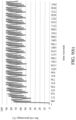
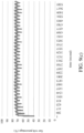
- FIG. 9(a) , FIG. 9(b) and FIG. 9(c) wherein FIG. 9(a) illustrates the temperature change of the second processor A11 on the expansion board A1, FIG. 9(b) illustrates the voltage change of the expansion fan A13 on the expansion board A1 without using the technology of the present disclosure to control the fan speed, and FIG. 9(c) illustrates the voltage change of the expansion fan A13 on the expansion board A1 according to the fan speed control method and device of the present disclosure to control the fan speed.
- the unit of the horizontal axis of FIG. 9(a) is time (second), the unit of the vertical axis is temperature (°C);
- the measured subject of FIG. 9(b) and FIG. 9(c) is a video graphics array (VGA), wherein the unit of the horizontal axis is time (second), and the unit of the vertical axis is fan volt percentage.
- VGA video graphics array
- the temperature of the second processor A1 1 on the expansion board A1 rises and falls rapidly between 50°C and 70°C, causing the fan volt of the expansion board A1 to rise and fall rapidly between 50V and 90V, wherein the range of this fan volt causes around 23 dBA to 37 dBA of noise range. Therefore, as can be seen from FIG. 9(a) and FIG. 9(b) , since the fan speed changes correspondingly with the temperature of the second processor A11 on the expansion board A1, the speed of the fan also rises and falls rapidly, thereby causing unpleasant noise.
- the fan speed control method and device As shown in FIG. 9(c) , the fan speed control method and device according to the present disclosure, the fan volt of the expansion fan A13 on the expansion board A1 correspondingly rises and falls smoothly between 60V and 70V, wherein the range of this fan volt only causes around 32 dBA to 35 dBA of noise range. Therefore, as can be seen from FIG. 9(c) , the fan speed control method and device according to the present disclosure may be used to ease the variation of the fan volt, thereby reducing unpleasant noise.
- the operating parameter indicates the temperature sensed by the first temperature sensor 35 or the second temperature sensor A12
- the fan parameter indicates the duty cycle used as a control signal
- the corresponding function indicates a corresponding relationship between temperature and duty cycle.
- the corresponding function is a lookup table between temperatures and duty cycles. Since the result of the second temperature sensor A12 sensing the second processor A11 fluctuates rapidly, if the sensing result of the second temperature sensor A12 is used to look up the duty cycle or converted into the duty cycle, and the duty cycle is used to control the expansion fan A13, the speed of the expansion fan A13 also fluctuates rapidly, which causes the user to easily perceive the change of the speed and the accompanying noise.
- the speed of the expansion fan A13 also fluctuates smoothly.
- the present disclosure uses the controller 31 on the main board 30 along with the sensing result of the first temperature sensor 35 to look up the duty cycle or converted into the duty cycle, then the signal of the duty cycle is transmitted to the expansion fan A13 through the expansion slot 33, thereby controlling the speed of the expansion fan A13. Accordingly, the violent fluctuation of the expansion fan A13 may be avoided, the user may not perceive the speed variation of the expansion fan A13 and the accompanying noise.
- the present disclosure further provides a fan speed control method performed by the controller 31 on the main board 30.
- the controller 31 obtains the first load parameter associated with the main board 30, and controls the expansion fan A13 on the expansion board A1 according to the first load parameter, wherein the first load parameter may be a parameter reflecting the operation condition of the main board 10, and includes temperature of the main board 30, speed or duty cycle of the system fan 32, the processor usage of the processor disposed on the main board 30 or wattage consumption of the main board 30 etc.
- the controller 31 on the main board 30 controls the fan according to the corresponding function and the operating parameter corresponding to the first load parameter.
- the operating parameter indicates the temperature sensed by the first temperature sensor 35
- the fan parameter indicates the duty cycle used as the control signal
- the corresponding function indicates a lookup table containing the relationships between temperatures and duty cycles.
- the controller 31 on the main board 30 uses the temperature sensed by the first temperature sensor 35 and the lookup table between temperatures and duty cycles to obtain the duty cycle, and transmits the signal of the duty cycle to the expansion fan A13, thereby controlling the speed of the expansion fan A13.
- the fan speed control method and device may allow the speed of the fan to not fluctuates rapidly by the operation condition of the expansion board when cooling is performed using the fan. Accordingly, the fan speed may be steadily controlled, thereby easing the noise caused by the operating fan.
Landscapes
- Engineering & Computer Science (AREA)
- Theoretical Computer Science (AREA)
- General Engineering & Computer Science (AREA)
- Human Computer Interaction (AREA)
- Physics & Mathematics (AREA)
- General Physics & Mathematics (AREA)
- Mechanical Engineering (AREA)
- Cooling Or The Like Of Electrical Apparatus (AREA)
- Control Of Positive-Displacement Air Blowers (AREA)
Abstract
A fan speed control method, performed by a controller, includes: obtaining a first load parameter associated with a main board; obtaining a second load parameter associated with an expansion board; determining a greater one of the first load parameter and the second load parameter; and controlling a fan according to the greater one.
Description
- This disclosure relates to a fan speed control method and device.
- For commercially available computer models, it has always been a goal of engineers to avoid overheating of the casing while maintaining the balance of system performance. For example, prior art includes acquiring current tachometers of multiple heat sources of the electronic device, determining the corresponding rotational speed of the fan according to the selected current tachometers, and setting the fan corresponding to the heat sources as the rotational speed.
- Accordingly, this disclosure provides a fan speed control method and device.
- According to one or more embodiment of this disclosure, a fan speed control method, performed by a controller, includes: obtaining a first load parameter associated with a main board; obtaining a second load parameter associated with an expansion board; determining a greater one of the first load parameter and the second load parameter; and controlling a fan according to the greater one.
- According to one or more embodiment of this disclosure, a fan speed control device includes: a main board, an expansion slot, a fan and a controller. The expansion slot is disposed on the main board and configured to electrically connect an expansion board. The fan is disposed on the expansion board. The controller is disposed on the main board, electrically connected to the expansion slot, and configured to perform: obtaining a first load parameter associated with the main board; obtaining a second load parameter associated with the expansion board; determining a greater one of the first load parameter and the second load parameter; and controlling a fan according to the greater one.
- In view of the above description, the fan speed control method and device according to one or more embodiments of the present disclosure may allow the speed of the fan to not fluctuates rapidly by the operation condition of the expansion board when cooling is performed using the fan. Accordingly, the fan speed may be steadily controlled, thereby easing the noise caused by the operating fan.
- The present disclosure will become more fully understood from the detailed description given herein below and the accompanying drawings which are given by way of illustration only and thus are not limitative of the present disclosure and wherein:
-
FIG. 1 is a block diagram illustrating a fan speed control device and an expansion board according to an embodiment of the present disclosure; -
FIG. 2 is a flowchart illustrating a fan speed control method according to an embodiment of the present disclosure; -
FIG. 3 is a block diagram illustrating a fan speed control device and an expansion board according to another embodiment of the present disclosure; -
FIG. 4 is a flowchart illustrating a method of controlling a fan according to an embodiment of the present disclosure; -
FIG. 5(a) is a flowchart illustrating a method of obtaining a first load parameter according to an embodiment of the present disclosure;FIG. 5(b) is a flowchart illustrating a method of obtaining a second load parameter according to an embodiment of the present disclosure; -
FIG. 6 is a flowchart illustrating a method of obtaining a second load parameter according to another embodiment of the present disclosure; -
FIG. 7 is a block diagram illustrating a fan speed control device and an expansion board according to yet another embodiment of the present disclosure; -
FIG. 8 is a flowchart illustrating a fan speed control method according to another embodiment of the present disclosure; and -
FIG. 9(a) illustrates the temperature change of the second processor A11 on the expansion board A1,FIG. 9(b) illustrates the voltage change of the expansion fan A13 on the expansion board A1 without using the technology of the present disclosure to control the fan speed,FIG. 9(c) illustrates the voltage change of the expansion fan A13 on the expansion board A1 according to the fan speed control method and device of the present disclosure to control the fan speed. - In the following detailed description, for purposes of explanation, numerous specific details are set forth in order to provide a thorough understanding of the disclosed embodiments. According to the description, claims and the drawings disclosed in the specification, one skilled in the art may easily understand the concepts and features of the present invention. The following embodiments further illustrate various aspects of the present invention, but are not meant to limit the scope of the present invention.
- It should be noted that the following description of the fan speed control method of one or more embodiments may be performed by a controller, and may be performed periodically or non-periodically after a fan speed control device is activated. Further, after the fan speed control device is activated, the controller may also wait for a preset period of time to perform the fan speed control method, wherein said preset period of time is, for example, 30 seconds, 40 seconds or 1 minute, the present disclosure is not limited thereto. The "speed" described in the present disclosure means the rotation speed of the fan.
- Please refer to
FIG. 1 , whereinFIG. 1 is a block diagram illustrating a fan speed control device and an expansion board according to an embodiment of the present disclosure. As shown inFIG. 1 , the fanspeed control device 1 includes amain board 10, acontroller 11, asystem fan 12 and anexpansion slot 13. The fanspeed control device 1 may be disposed on a computer host, that is, the fanspeed control device 1 may be a part of a computer host. Thecontroller 11, thesystem fan 12 and theexpansion slot 13 are disposed on themain board 10. Thecontroller 11 is electrically connected to thesystem fan 12 and theexpansion slot 13. Themain board 10 may also be referred to as a motherboard with one or more processors disposed thereon. Thecontroller 11 may include one or more controllers, said controller is, for example, an embedded controller (EC), a microcontroller, a programmable logic controller or any other controller with signal processing function. Thesystem fan 12 may be configured to dissipate heat from one or more elements on themain board 10, and is controlled by thecontroller 11. Thesystem fan 12 is disposed on themain board 10 and corresponds to theexpansion slot 13. In other words, in addition to cooling elements on themain board 10, thesystem fan 12 may further be used for cooling element(s) (for example, an the expansion board A1) connected to theexpansion slot 13. Themain board 10, thecontroller 11, thesystem fan 12 and theexpansion slot 13 may be disposed on the same computer. Theexpansion slot 13 may include one or more of a peripheral component interconnect express (PCIE), a universal serial bus (USB) and a high definition multimedia interface (HDMI), the present disclosure is not limited thereto. Theexpansion slot 13 is disposed on themain board 10 and configured to electrically connect the expansion board A1, wherein another processor and another fan (for example, the expansion fan described below) may be disposed on the expansion board A1. In short, the expansion board A1 may be a board for carrying (or mounting) and connecting external processor. - Please refer to
FIG. 1 and FIG. 2 , whereinFIG. 2 is a flowchart illustrating a fan speed control method according to an embodiment of the present disclosure. The fan speed control method is performed by thecontroller 11, and as shown inFIG. 2 , includes: step S101: obtaining a first load parameter associated with a main board; step S103: obtaining a second load parameter associated with an expansion board; step S105: determining a greater one of the first load parameter and the second load parameter; and step S107: controlling a fan according to the greater one. It should be noted that step S101 may be performed before or after step S103, step S101 may also be performed with step S103 at the same time. - In step S101, the
controller 11 obtains the first load parameter associated with operation condition of themain board 10. The first load parameter may be a parameter reflecting the operation condition corresponding to themain board 10, and may include a temperature of themain board 10, a temperature of a processor disposed on themain board 10, fan speed or duty cycle of thesystem fan 12, a processor usage of the processor disposed on themain board 10 or wattage consumption of themain board 10 etc. - In step S103, the
controller 11 obtains the second load parameter associated with the operation condition of the expansion board A1. For example, thecontroller 11 obtains the second load parameter of the expansion board A1 through theexpansion slot 13. The second load parameter may be a parameter reflecting the operation condition corresponding to theexpansion slot 13, and may include a temperature of a processor disposed on the expansion board A1, fan speed or duty cycle corresponding to the temperature of the processor, fan speed or duty cycle of another fan on the expansion board A1, a processor usage of the processor or wattage consumption of the expansion board A1 etc. - In step S105, the
controller 11 determines a greater one of the first load parameter and the second load parameter. The first load parameter and the second load parameter used for comparison in step S105 are the same type of parameters. For example, in step S105, if the first load parameter is the temperature of themain board 10, the second load parameter is the temperature of the processor on the expansion board A1; if the first load parameter is the processor usage of the processor disposed on themain board 10, the second load parameter is the processor usage of the processor disposed on the expansion board A1. - In step S107, the
controller 11 controls the speed of thesystem fan 12 according to greater one of the two load parameters, or controls the speed of said another fan on the expansion board A1 according to the greater one of the two load parameters. For example, thecontroller 11 controls said another fan on the expansion board A1 or thesystem fan 12 according to the fan speed or duty cycle corresponding to the greater load parameter. In an example, assuming that the first load parameter is the temperature of themain board 10 and the second load parameter is the temperature of the processor disposed on the expansion board A1, when the second load parameter is greater than the first load parameter, thecontroller 11 may control said another fan on the expansion board A1 or thesystem fan 12 based on the fan speed corresponding to the temperature of the processor disposed on the expansion board A1. In another example, assuming that the first load parameter is the fan speed corresponding to the temperature of themain board 10 and the second load parameter is the fan speed corresponding to the temperature of the processor disposed on the expansion board A1, when the second load parameter is greater than the first load parameter, thecontroller 11 may control said another fan on the expansion board A1 or thesystem fan 12 based on the fan speed corresponding to the temperature of the processor disposed on the expansion board A1. - Further, in step S107, the
controller 11 may control said another fan on the expansion board A1 or thesystem fan 12 according to an operating parameter-fan parameter corresponding function (referred to as "the corresponding function" hereinafter) corresponding to said greater one. For example, the first load parameter and the second load parameter may be fan speeds, the operating parameter may be temperatures. Assuming that the first load parameter is the greater one, thecontroller 11 may select the corresponding function corresponding to themain board 10 according to the first load parameter, read the selected corresponding function according to the temperature of themain board 10 to determine a corresponding fan parameter, and control said another fan on the expansion board A1 or thesystem fan 12 according to the fan parameter. - In other words, the operating parameter corresponding to the first load parameter may be the temperature of the
main board 10, the processor usage of the processor disposed on themain board 10 or the wattage consumption of themain board 10. The operating parameter corresponding to the second load parameter may be the temperature of the processor disposed on the expansion board A1, the processor usage of the processor disposed on the expansion board A1 or the wattage consumption of the expansion board A1. Themain board 10 and the expansion board A1 may each has a corresponding function, which records corresponding relationship between a plurality of operating parameters and a plurality of fan parameters. The corresponding function is, for example, table 1 and table 2 as shown below, and may be stored in thecontroller 11, wherein the numbers of pieces of data of the operating parameter in the fan parameter table 1 and table 2 are only examples.Table 1 Corresponding function of the main board first operating parameter first fan parameter second operating parameter second fan parameter Table 2 Corresponding function of the expansion board third operating parameter third fan parameter fourth operating parameter fourth fan parameter - In other words, in step S107, the
controller 11 may refer to table 1 or table 2, to select the corresponding function according to the greater load parameter, determine the fan parameter according to the greater load parameter and the selected corresponding function, and control said another fan on the expansion board A1 or thesystem fan 12 according to the fan parameter. Take table 1 and table 2 for example, assuming that the operating parameter that themain board 10 corresponds to is the temperature of themain board 10, the operating parameter that the expansion board A1 corresponds to is the temperature of the processor disposed on the expansion board A1, and the second load parameter is greater than the first load parameter, then in step S107, thecontroller 11 may refer to table 2 to determine that the operating parameter (temperature) that the expansion board A1 corresponds to belongs to the third operating parameter or the fourth operating parameter. If the operating parameter (temperature) that the expansion board A1 corresponds to belongs to the third operating parameter, thecontroller 11 controls said another fan on the expansion board A1 or thesystem fan 12 according to the third fan parameter; if the operating parameter (temperature) that the expansion board A1 corresponds to belongs to the fourth operating parameter, thecontroller 11 controls said another fan on the expansion board A1 or thesystem fan 12 according to the fourth fan parameter. It should be noted that the first operating parameter to the fourth operating parameter shown in table 1 and table 2 may each be a value or a range. Take the expansion board A1 for example, the operating parameter that the expansion board A1 corresponds to belonging to the third operating parameter may mean that the operating parameter that the expansion board A1 corresponds to equals to the third operating parameter, or the operating parameter falls within the numerical range of the third operating parameter. In the embodiment where the first operating parameter to the fourth operating parameter each is a numerical range, an upper limit of the first operating parameter of the corresponding function of themain board 10 may be a lower limit of the second operating parameter, the third operating parameter of the corresponding function of the expansion board A1 may be a lower limit of the fourth operating parameter. In addition, the first operating parameter may not overlap, partially overlap or completely overlap the third operating parameter, and the second operating parameter may not overlap, partially overlap or completely overlap the fourth operating parameter. - According to one or more embodiments described above, rapid increase and decrease of the fan speed caused by the operation condition of the expansion board may be avoided when cooling is performed using the fan. Accordingly, the fan speed may be steadily controlled, thereby reducing the noise generated when controlling the fan.
- Please refer to
FIG. 3 , whereinFIG. 3 is a block diagram illustrating a fan speed control device and an expansion board according to another embodiment of the present disclosure. As shown inFIG. 3 , the fanspeed control device 2 according to another embodiment of the present disclosure includes amain board 20, acontroller 21, asystem fan 22, anexpansion slot 23 and afirst processor 24, wherein theexpansion slot 23 is electrically connected to the expansion board A1. The fanspeed control device 2 may be disposed on a computer host, that is, the fanspeed control device 2 may be a part of a computer host. The implementation of themain board 20, thecontroller 21, thesystem fan 22 and theexpansion slot 23 may be the same as themain board 10, thecontroller 11, thesystem fan 12 and theexpansion slot 13 ofFIG. 1 , their details are not repeated herein. The expansion board A1 includes a second processor A11. For example, thefirst processor 24 may be a central processing unit (CPU), the second processor A11 may be a graphic processing unit (GPU). - Please refer to
FIG. 3 andFIG. 4 , whereinFIG. 4 is a flowchart illustrating a method of controlling a fan according to an embodiment of the present disclosure. The fan speed control method shown inFIG. 4 is performed by thecontroller 21, and as shown inFIG. 4 , in addition to step S101 and step S103 shown inFIG. 2 , the method further includes: step S201: determining a relationship between the first load parameter and the second load parameter; if the second load parameter is lower than the first load parameter, performing step S203: controlling the fan according to a first operating parameter-fan parameter corresponding function and an operating parameter of the first processor; if the second load parameter equals to the first load parameter, performing step S205: controlling the fan according to the first operating parameter-fan parameter corresponding function and the operating parameter of the first processor or controlling the fan according to a second operating parameter-fan parameter corresponding function and an operating parameter of the second processor; and if the second load parameter is greater than the first load parameter, performing step S207: controlling the fan according to the second operating parameter-fan parameter corresponding function and the operating parameter of the second processor. Step S201 shown inFIG. 4 may be regarded as a detail flowchart of an embodiment of step S105 ofFIG. 2 , steps S203, S205 and S207 shown inFIG. 4 may be regarded as a detail flowchart of an embodiment of step S107 ofFIG. 2 . - In the embodiment of
FIG. 3 andFIG. 4 , the first load parameter is the load parameter of thefirst processor 24 disposed on themain board 20, the second load parameter is the load parameter of the second processor A11 disposed on the expansion board A1. In addition, examples of the first operating parameter-fan parameter corresponding function (referred to as "the first corresponding function" hereinafter) and the second operating parameter-fan parameter corresponding function (referred to as "the second corresponding function" hereinafter) are respectively shown in table 3 and table 4 below, and the first corresponding function and the second corresponding function may be stored in thecontroller 21. The first candidate operating parameter to the fourth candidate operating parameter shown in table 3 and table 4 may each be a numerical range, and an upper limit of the first candidate operating parameter of the first corresponding function may be a lower limit the second candidate operating parameter, and an upper limit of the third candidate operating parameter of the second corresponding function may be a lower limit of the fourth candidate operating parameter.Table 3 the first corresponding function first candidate operating parameter first candidate fan parameter second candidate operating parameter second candidate fan parameter Table 4 the second corresponding function third candidate operating parameter third candidate fan parameter fourth candidate operating parameter fourth candidate fan parameter - The first candidate operating parameter and the second candidate operating parameter may be the same as the operating parameter corresponding to the first load parameter as described above. In other words, each of the first candidate operating parameter and the second candidate operating parameter may be temperature of the
main board 20, processor usage of thefirst processor 24 or wattage consumption of themain board 20. The third candidate operating parameter and the fourth candidate operating parameter may be the same as the operating parameter corresponding to the second load parameter as described above. In other words, each of the third candidate operating parameter and the fourth candidate operating parameter may be temperature of the second processor A11, processor usage of the second processor A11 or wattage consumption of the expansion board A1. - In step S201, the
controller 21 determines the numerical relationship between the first load parameter and the second load parameter for thecontroller 21 to perform subsequent steps according to the determination result. - If the second load parameter is lower than the first load parameter, in step S203, the
controller 21 looks up the first corresponding function for the candidate operating parameter that themain board 20 corresponds to according to the operating parameter of thefirst processor 24, and controls said another fan on the expansion board A1 or thesystem fan 22 according to the candidate fan parameter that the candidate operating parameter corresponds to. - If the second load parameter equals to the first load parameter, in step S205, the
controller 21 looks up the first corresponding function for the candidate operating parameter that themain board 20 corresponds to according to the operating parameter of thefirst processor 24, and controls said another fan on the expansion board A1 or thesystem fan 22 according to the candidate fan parameter that the candidate operating parameter corresponds to; or, thecontroller 21 looks up the second corresponding function for the candidate operating parameter t according to the operating parameter of the second processor A11, and controls said another fan on the expansion board A1 or thesystem fan 22 according to the candidate fan parameter that the candidate operating parameter corresponds to. Further, when the second load parameter equals to the first load parameter, thecontroller 21 may control said another fan on the expansion board A1 or thesystem fan 22 according to the operating parameter of thefirst processor 24 and the first corresponding function, so that the speed of said another fan on the expansion board A1 or thesystem fan 22 may be more steady. - If the second load parameter is greater than the first load parameter, in step S207, the
controller 21 looks up the second corresponding function for the candidate operating parameter corresponding to the expansion board A1 according to the operating parameter of the second processor A11, and controls said another fan on the expansion board A1 or thesystem fan 22 according to the candidate fan parameter that the candidate operating parameter corresponds to. - Take the first corresponding function as an example, the method of looking up the first corresponding function for the candidate operating parameter , and controlling said another fan on the expansion board A1 or the
system fan 22 according to the candidate fan parameter that the candidate operating parameter corresponds to may include: thecontroller 21 determining which one of the candidate operating parameters in the first corresponding function equals to the operating parameter, thereby controlling said another fan on the expansion board A1 or thesystem fan 22 according to the candidate fan parameter that the candidate operating parameter corresponds to; or, the candidate operating parameter being a numerical range, and thecontroller 21 determining which one of the candidate operating parameters in the first corresponding function that the first corresponding function falls within, thereby controlling said another fan on the expansion board A1 or thesystem fan 22 according to the candidate fan parameter that the candidate operating parameter corresponds to. In other words, table 1 may be the same as table 3, and table 2 may be the same as table 4. - Please refer to
FIG. 3 andFIG. 5(a) , whereinFIG. 5(a) is a flowchart illustrating a method of obtaining a first load parameter according to an embodiment of the present disclosure. Steps shown inFIG. 5(a) may be regarded as a detail flowchart of an embodiment of step S101 ofFIG. 2 . As shown inFIG. 5(a) , the method of obtaining the first load parameter includes: step S301a: obtaining a first operating parameter of a first processor disposed on the main board; and step S303a: obtaining a first fan parameter corresponding to the first operating parameter from the first operating parameter-fan parameter corresponding function as the first load parameter. - In step S301a, the
controller 21 obtains the first operating parameter of thefirst processor 24. In step S303a, thecontroller 21 obtains the first fan parameter corresponding to the first operating parameter according to the first corresponding function as shown in table 3, and uses the obtained first fan parameter as the first load parameter. - Specifically, the
controller 21 may look for the candidate operating parameter that the first operating parameter belongs to by looking up the first corresponding function (table 3), and uses the candidate fan parameter corresponding to the candidate operating parameter as the first load parameter. The method of thecontroller 21 looking for the first operating parameter in the first corresponding function is as described above, and is not repeated herein. - Please refer to
FIG. 3 andFIG. 5(b) , whereinFIG. 5(b) is a flowchart illustrating a method of obtaining a second load parameter according to an embodiment of the present disclosure. Steps shown inFIG. 5(b) may be regarded as a detail flowchart of an embodiment of step S103 ofFIG. 2 . As shown inFIG. 5(b) , the method of obtaining the second load parameter includes: step S301b: obtaining a second operating parameter of a second processor disposed on the expansion board; and step S303b: obtaining a second fan parameter corresponding to the second operating parameter from the second operating parameter-fan parameter corresponding function as the second load parameter. - In step S301b, the
controller 21 obtains the second operating parameter of the second processor A11. In step S303b, thecontroller 21 obtains the second fan parameter corresponding to the second operating parameter according to the second corresponding function as shown in table 4, and uses the obtained second fan parameter as the second load parameter. - Specifically, the
controller 21 may look for the candidate operating parameter that the second operating parameter belongs to by looking up the second corresponding function (table 4), and uses the candidate fan parameter corresponding to the candidate operating parameter as the second load parameter. The method of thecontroller 21 looking for the second operating parameter in the second corresponding function is as described above, and is not repeated herein. - It should be noted that the physical unit of the first fan parameter and the physical unit of the second fan parameter are duty cycle of pulse-width modulation (PWM), or revolutions per minute (RPM) of the
system fan 22. In addition, the first corresponding function describes a first corresponding policy of the first fan parameter corresponding to the first operating parameter, or a first numerical lookup table (for example, table 3) listing the first fan parameter corresponding to the first operating parameter, or a first function graph presenting the first fan parameter corresponding to the first operating parameter. The second corresponding function describes a second corresponding policy of the second fan parameter corresponding to the second operating parameter, or a second numerical lookup table (for example, table 4) listing the second fan parameter corresponding to the second operating parameter, or a second function graph presenting the second fan parameter corresponding to the second operating parameter. - Please refer to
FIG. 3 andFIG. 6 , whereinFIG. 6 is a flowchart illustrating a method of obtaining a second load parameter according to another embodiment of the present disclosure. Steps shown inFIG. 6 may be regarded as a detail flowchart of an embodiment of step S303b ofFIG. 5(b) . In the embodiment ofFIG. 6 , the second corresponding function includes a plurality of candidate operating parameter ranges and a plurality of candidate fan parameter ranges corresponding to the candidate operating parameter ranges, the format may be the same as table 4. For example, each of the candidate operating parameter ranges is a temperature range of the expansion board A1, and each of the candidate fan parameter ranges is a duty cycle range of thesystem fan 22. The candidate operating parameter ranges do not overlap with each other, an upper limit of each candidate operating parameter range is a lower limit of the next candidate operating parameter range; the candidate fan parameter ranges do not overlap with each other, an upper limit of each fan parameter range is a lower limit of the next fan parameter range. As shown inFIG. 6 , the method of obtaining the second load parameter includes: step S401: using one of the plurality of candidate operating parameter ranges in which the second operating parameter of the second processor falls into as a target operating parameter range, and using one of the plurality of candidate fan parameter ranges corresponding to the target operating parameter range as a target fan parameter range; step S403: performing interpolation according to the second operating parameter of the second processor, the target operating parameter range and the target operating parameter range to obtain a second interpolated fan parameter; and step S405: using a sum of the second interpolated fan parameter and a lower limit of the target fan parameter range as the second load parameter. - In step S401, the
controller 21 uses the candidate operating parameter range which the second operating parameter falls into as the target operating parameter range, and uses the fan parameter range corresponding to the target operating parameter range as the target fan parameter range. For example, the candidate operating parameter range is a temperature range, the second operating parameter is a temperature of the second processor A11, thecontroller 21 uses the candidate operating parameter range containing the value of the temperature of the second processor A11 as the target operating parameter range, and uses the candidate fan parameter range (for example, the duty cycle range) corresponding to the target operating parameter range as the target fan parameter range. - In step S403, the
controller 21 performs interpolation according to the second operating parameter, the target operating parameter range and the target fan parameter range of the second processor A11 to obtain the second interpolated fan parameter, specifically, thecontroller 21 subtracts the lower limit of the target operating parameter range from the upper limit of the target operating parameter range to obtain a first value, subtracts the lower limit of the target fan parameter range from the upper limit of the target fan parameter range to obtain a second value, subtracts the target operating parameter range from the second operating parameter to obtain a third value, and dividing a value of the third value multiplied with the second value by the first value to obtain the second interpolated fan parameter. In step S405, thecontroller 21 uses a sum of the second interpolated fan parameter and the lower limit of the target fan parameter range as the second load parameter. - In addition, the implementation of step S303a of
FIG. 5(a) may also adopt the process as shown inFIG. 6 to obtain the first load parameter. In other words, the method of obtaining the first load parameter may be: obtaining one of the candidate operating parameter ranges of the first corresponding function that the first operating parameter of the first processor falls into as the target operating parameter range, and using one of the candidate fan parameter ranges of the first corresponding function corresponding to the target operating parameter range as the target fan parameter range; performing interpolation according to the first operating parameter of the first processor, the target operating parameter range and the target fan parameter range to obtain a first interpolated fan parameter; and using a sum of the first interpolated fan parameter and the target fan parameter range as the first load parameter. - Please refer to
FIG. 7 , whereinFIG. 7 is a block diagram illustrating a fan speed control device and an expansion board according to yet another embodiment of the present disclosure. As shown inFIG. 7 , the fanspeed control device 3 according to yet another embodiment of the present disclosure includes amain board 30, acontroller 31, asystem fan 32, anexpansion slot 33, afirst processor 34 and afirst temperature sensor 35, wherein theexpansion slot 33 is electrically connected to the expansion board A1. Thesystem fan 32, theexpansion slot 33, thefirst processor 34 and thefirst temperature sensor 35 are electrically connected to or in communication connection with thecontroller 31. Thefirst temperature sensor 35 is configured to sense an operating temperature of themain board 30, output the sensing result of thefirst temperature sensor 35 to thecontroller 31. Due to a highly fluctuated operating temperature of thefirst processor 34, in comparison, the operating temperature of themain board 30 is relatively moderate, the sensing result of a second temperature sensor A12 is also relatively moderate. The implementation of themain board 30, thecontroller 31, thesystem fan 32, theexpansion slot 33 and thefirst processor 34 are the same as themain board 20, thecontroller 21, thesystem fan 22, theexpansion slot 23 and thefirst processor 24 shown inFIG. 3 , their details are not repeated herein. The expansion board A1 includes a second processor A11, a second temperature sensor A12 and an expansion fan A13. The expansion board A1 and the second processor A11 may be the same as the expansion board A1 and the second processor A11 ofFIG. 3 respectively. The second temperature sensor A12 is configured to sense the temperature of the second processor A11, the expansion fan A13 is controlled by thecontroller 31. In addition, inFIG. 1 andFIG. 3 , the controller may also be connected to the first temperature sensor which is used to sense the operating temperature of the main board, the expansion board may also be disposed with the second processor and the second temperature sensor for sensing the temperature of the second processor, and the sensing result may be transmitted to the controller through the expansion slot. - Please refer to
FIG. 7 andFIG. 8 , whereinFIG. 8 is a flowchart illustrating a fan speed control method according to another embodiment of the present disclosure. Steps shown inFIG. 8 may be performed by thecontroller 31, and may be regarded as a detail flowchart of an embodiment of step S207 ofFIG. 4 . As shown inFIG. 8 , the fan speed control method includes: step S501: obtaining a plurality of operating temperatures of the second processor during a preset duration; step S503: calculating an average temperature according to the plurality of operating temperatures; step S505: obtaining a duty cycle corresponding to the average temperature from the second operating parameter-fan parameter corresponding function; and step S507: controlling the fan according to the duty cycle. - In step S501, the
controller 31 obtains the operating temperatures of the second processor A11 during the preset duration, wherein the operating temperatures of the second processor A11 may be obtained by the sensing of the second temperature sensor A12, and the second temperature sensor A12 transmits the sensing result to thecontroller 31. Because the operating temperatures of the second processor A11 fluctuate significantly, the sensing result of the second temperature sensor A12 also fluctuates significantly. For example, the preset duration may be 30 seconds, 40 seconds or 1 minute, and the length of the preset duration may be the same as the preset period of time as described above, the present disclosure does not limit the length of the preset duration. - In step S503, the
controller 31 calculates the average temperature of the operating temperatures. In step S505, thecontroller 31 obtains the duty cycle (the second fan parameter) corresponding to the average temperature from the second corresponding function. In addition, if the second corresponding function includes the plurality of candidate operating parameter ranges and the plurality of candidate fan parameter ranges corresponding to the candidate operating parameter ranges, the method of obtaining the duty cycle corresponding to the average temperature may also be performing the interpolation as described above according to the average temperature, the target operating parameter range and the target fan parameter range. In step S507, thecontroller 31 controls the speed of the expansion fan A13 according to the duty cycle directly obtained from the second corresponding function or from the interpolation. Further, in addition to storing table 3 and table 4 (and/or table 1 and table 2), thecontroller 31 may further store another corresponding function, which includes the plurality of operating parameters of thefirst processor 34 and the corresponding fan parameters of thesystem fan 22. Thecontroller 31 may obtain the duty cycle corresponding to the average temperature from the corresponding function of thesystem fan 22, and control the speed of thesystem fan 22 according to the duty cycle. The operating parameter of thefirst processor 34 described above may be the temperature or processor usage of themain board 30. Specifically, in the embodiment where the temperature of thefirst processor 34 is used as the operating parameter of thefirst processor 34, the fanspeed control device 3 further includes thefirst temperature sensor 35 connected to thecontroller 31, thefirst temperature sensor 35 is configured to sense the temperature of themain board 30 or the temperature of thefirst processor 34 itself. - Please refer to
FIG. 9(a) ,FIG. 9(b) andFIG. 9(c) , whereinFIG. 9(a) illustrates the temperature change of the second processor A11 on the expansion board A1,FIG. 9(b) illustrates the voltage change of the expansion fan A13 on the expansion board A1 without using the technology of the present disclosure to control the fan speed, andFIG. 9(c) illustrates the voltage change of the expansion fan A13 on the expansion board A1 according to the fan speed control method and device of the present disclosure to control the fan speed. The unit of the horizontal axis ofFIG. 9(a) is time (second), the unit of the vertical axis is temperature (°C); the measured subject ofFIG. 9(b) andFIG. 9(c) is a video graphics array (VGA), wherein the unit of the horizontal axis is time (second), and the unit of the vertical axis is fan volt percentage. - As shown in
FIG. 9(a) andFIG. 9(b) , the temperature of thesecond processor A1 1 on the expansion board A1 rises and falls rapidly between 50°C and 70°C, causing the fan volt of the expansion board A1 to rise and fall rapidly between 50V and 90V, wherein the range of this fan volt causes around 23 dBA to 37 dBA of noise range. Therefore, as can be seen fromFIG. 9(a) andFIG. 9(b) , since the fan speed changes correspondingly with the temperature of the second processor A11 on the expansion board A1, the speed of the fan also rises and falls rapidly, thereby causing unpleasant noise. - As shown in
FIG. 9(c) , the fan speed control method and device according to the present disclosure, the fan volt of the expansion fan A13 on the expansion board A1 correspondingly rises and falls smoothly between 60V and 70V, wherein the range of this fan volt only causes around 32 dBA to 35 dBA of noise range. Therefore, as can be seen fromFIG. 9(c) , the fan speed control method and device according to the present disclosure may be used to ease the variation of the fan volt, thereby reducing unpleasant noise. - In a specific embodiment, the operating parameter indicates the temperature sensed by the
first temperature sensor 35 or the second temperature sensor A12, and the fan parameter indicates the duty cycle used as a control signal, and the corresponding function indicates a corresponding relationship between temperature and duty cycle. Specifically, the corresponding function is a lookup table between temperatures and duty cycles. Since the result of the second temperature sensor A12 sensing the second processor A11 fluctuates rapidly, if the sensing result of the second temperature sensor A12 is used to look up the duty cycle or converted into the duty cycle, and the duty cycle is used to control the expansion fan A13, the speed of the expansion fan A13 also fluctuates rapidly, which causes the user to easily perceive the change of the speed and the accompanying noise. In comparison, since the result of themain board 30 sensing thefirst temperature sensor 35 fluctuates smoothly, if the sensing result of thefirst temperature sensor 35 is used to look up the duty cycle or converted into the duty cycle and the duty cycle is used to control the expansion fanA13, the speed of the expansion fan A13 also fluctuates smoothly. The present disclosure uses thecontroller 31 on themain board 30 along with the sensing result of thefirst temperature sensor 35 to look up the duty cycle or converted into the duty cycle, then the signal of the duty cycle is transmitted to the expansion fan A13 through theexpansion slot 33, thereby controlling the speed of the expansion fan A13. Accordingly, the violent fluctuation of the expansion fan A13 may be avoided, the user may not perceive the speed variation of the expansion fan A13 and the accompanying noise. - In another specific embodiment, the present disclosure further provides a fan speed control method performed by the
controller 31 on themain board 30. Thecontroller 31 obtains the first load parameter associated with themain board 30, and controls the expansion fan A13 on the expansion board A1 according to the first load parameter, wherein the first load parameter may be a parameter reflecting the operation condition of themain board 10, and includes temperature of themain board 30, speed or duty cycle of thesystem fan 32, the processor usage of the processor disposed on themain board 30 or wattage consumption of themain board 30 etc. - In still another specific embodiment, the
controller 31 on themain board 30 controls the fan according to the corresponding function and the operating parameter corresponding to the first load parameter. Specifically, the operating parameter indicates the temperature sensed by thefirst temperature sensor 35, the fan parameter indicates the duty cycle used as the control signal, and the corresponding function indicates a lookup table containing the relationships between temperatures and duty cycles. In other words, thecontroller 31 on themain board 30 uses the temperature sensed by thefirst temperature sensor 35 and the lookup table between temperatures and duty cycles to obtain the duty cycle, and transmits the signal of the duty cycle to the expansion fan A13, thereby controlling the speed of the expansion fan A13. - In view of the above description, the fan speed control method and device according to one or more embodiments of the present disclosure may allow the speed of the fan to not fluctuates rapidly by the operation condition of the expansion board when cooling is performed using the fan. Accordingly, the fan speed may be steadily controlled, thereby easing the noise caused by the operating fan.
Claims (15)
- A fan speed control method, performed by a controller (11,21), comprising:obtaining (S101) a first load parameter associated with a main board (10,20);obtaining (S103) a second load parameter associated with an expansion board (A1);determining (S105) a greater one of the first load parameter and the second load parameter; andcontrolling (S107) a fan (12,22) according to the greater one.
- The fan speed control method according to claim 1, wherein controlling the fan (12,22) according to the greater one comprises:
controlling the fan (12,22) according to an operating parameter-fan parameter corresponding function corresponding to the greater one. - The fan speed control method according to claim 2, wherein the first load parameter is a load parameter of a first processor (24) disposed on the main board (10,20), the second load parameter is a load parameter of a second processor (A11) disposed on the expansion board (A1), wherein controlling the fan (12,22) according to the operating parameter-fan parameter corresponding function corresponding to the greater one comprises:controlling (S203) the fan (12,22) according to a first operating parameter-fan parameter corresponding function and an operating parameter of the first processor (24) when the second load parameter is lower than the first load parameter;controlling (S207) the fan (12,22) according to a second operating parameter-fan parameter corresponding function and an operating parameter of the second processor (A11) when the second load parameter is greater than the first load parameter; andcontrolling (S205) the fan (12,22) according to the first operating parameter-fan parameter corresponding function and the operating parameter of the first processor (24) or controlling the fan (12,22) according to the operating parameter and the second operating parameter-fan parameter corresponding function of the second processor (A11) when the second load parameter is equal to the first load parameter.
- The fan speed control method according to claim 1, wherein obtaining the first load parameter associated with the main board (10,20) comprises:obtaining (S301a) a first operating parameter of a first processor (24) disposed on the main board (10,20); andobtaining (S303a) a first fan parameter corresponding to the first operating parameter from a first operating parameter-fan parameter corresponding function as the first load parameter,wherein obtaining the second load parameter associated with the expansion board (A1) comprises:obtaining (S301b) a second operating parameter of a second processor (A11) disposed on the expansion board (A1); andobtaining (S303b) a second fan parameter corresponding to the second operating parameter from a second operating parameter-fan parameter corresponding function as the second load parameter.
- The fan speed control method according to claim 3, wherein the expansion board (A1) is further disposed with a temperature sensor for sensing a temperature of the second processor (A11), and controlling the fan (12,22) according to the operating parameter and the second operating parameter-fan parameter corresponding function of the second processor (A11) comprises:obtaining (S501) a plurality of operating temperatures of the second processor (A11) during a preset duration;calculating (S503) an average temperature according to the plurality of operating temperatures;obtaining (S505) a duty cycle corresponding to the average temperature from the second operating parameter-fan parameter corresponding function; andcontrolling (S507) the fan (12,22) according to the duty cycle.
- The fan speed control method according to claim 3, wherein the second operating parameter-fan parameter corresponding function comprises a plurality of candidate operating parameter ranges and a plurality of candidate fan parameter ranges corresponding to the plurality of candidate operating parameter ranges respectively, and obtaining the second fan parameter corresponding to the second operating parameter from the second operating parameter-fan parameter corresponding function as the second load parameter comprises:using (S401) one of the plurality of candidate operating parameter ranges in which the second operating parameter of the second processor (A11) falls into as a target operating parameter range, and using one of the plurality of candidate fan parameter ranges corresponding to the target operating parameter range as a target fan parameter range;performing (S403) interpolation according to the second operating parameter of the second processor (A11), the target operating parameter range and the target operating parameter range to obtain a second interpolated fan parameter; andusing (S405) a sum of the second interpolated fan parameter and a lower limit of the target fan parameter range as the second load parameter.
- The fan speed control method according to claim 2, wherein when the second load parameter is equal to the first load parameter, the fan (12,22) is controlled according to the operating parameter and the first operating parameter-fan parameter corresponding function of the first processor (24).
- The fan speed control method according to claim 4, wherein a physical unit of the first fan parameter or the second fan parameter is a duty cycle of a pulse-width modulation, or revolutions per minute of the fan.
- The fan speed control method according to claim 4, wherein the first operating parameter-fan parameter corresponding function describes a first corresponding policy of the first fan parameter corresponding to the first operating parameter, or a first numerical lookup table listing the first fan parameter corresponding to the first operating parameter, or a first function graph presenting the first fan parameter corresponding to the first operating parameter.
- The fan speed control method according to claim 4,
wherein the second operating parameter-fan parameter corresponding function describes a second corresponding policy of the second fan parameter corresponding to the second operating parameter, or a second numerical lookup table listing the second fan parameter corresponding to the second operating parameter, or a second function graph presenting the second fan parameter corresponding to the second operating parameter. - A fan speed control device (1,2), comprising:a main board (10,20);an expansion slot (13,23) disposed on the main board (10,20) and configured to electrically connect an expansion board (A1);a fan (12,22) disposed on the expansion board (A1); anda controller (11,21) disposed on the main board (10,20), electrically connected to the expansion slot (13,23), and configured to perform:obtaining a first load parameter associated with the main board (10,20);obtaining a second load parameter associated with the expansion board (A1);determining a greater one of the first load parameter and the second load parameter; andcontrolling the fan (12,22) according to the greater one.
- The fan speed control device (1,2) according to claim 8, wherein the controller (11,21) performs controlling the fan (12,22) according to the greater one comprises:
controlling the fan (12,22) according to an operating parameter-fan parameter corresponding function corresponding to the greater one. - The fan speed control device (1,2) according to claim 12, further comprising a first processor (24) disposed on the main board (10,20), wherein the first load parameter is a load parameter of the first processor (24), the second load parameter is a load parameter of a second processor (A11) disposed on the expansion board (A1), and the controller (11,21) performs controlling the fan (12,22) according to the operating parameter-fan parameter corresponding function corresponding to the greater one comprises:controlling the fan (12,22) according to a first operating parameter-fan parameter corresponding function and an operating parameter of the first processor (24) when the second load parameter is lower than the first load parameter;controlling the fan (12,22) according to a second operating parameter-fan parameter corresponding function and an operating parameter of the second processor (A11) when the second load parameter is greater than the first load parameter; andcontrolling the fan (12,22) according to the first operating parameter-fan parameter corresponding function and the operating parameter of the first processor (24) or controlling the fan (12,22) according to the operating parameter and the second operating parameter-fan parameter corresponding function of the second processor (A11) when the second load parameter is equal to the first load parameter.
- The fan speed control device (1,2) according to claim 11, whereinthe controller (11,21) performs obtaining the first load parameter associated with the main board (10,20) comprises:obtaining a first operating parameter of a first processor (24) disposed on the main board (10,20); andobtaining a first fan parameter corresponding to the first operating parameter from a first operating parameter-fan parameter corresponding function as the first load parameter,the controller (11,21) performs obtaining the first load parameter associated with the main board (10,20) comprises:obtaining a second operating parameter of a second processor (A11) disposed on the expansion board (A1); andobtaining a second fan parameter corresponding to the second operating parameter from a second operating parameter-fan parameter corresponding function as the second load parameter.
- The fan speed control device (1,2) according to claim 13, wherein the expansion board (A1) is further disposed with a temperature sensor for sensing a temperature of the second processor (A11), and the controller (11,21) performs controlling the fan (12,22) according to the operating parameter and the second operating parameter-fan parameter corresponding function of the second processor (A11) comprises:obtaining a plurality of operating temperatures of the second processor (A11) during a preset duration;calculating an average temperature according to the plurality of operating temperatures;obtaining a duty cycle corresponding to the average temperature from the second operating parameter-fan parameter corresponding function; andcontrolling the fan (12,22) according to the duty cycle.
Applications Claiming Priority (1)
| Application Number | Priority Date | Filing Date | Title |
|---|---|---|---|
| CN202310699543.6A CN119146081A (en) | 2023-06-14 | 2023-06-14 | Fan rotating speed control method and device |
Publications (1)
| Publication Number | Publication Date |
|---|---|
| EP4477890A1 true EP4477890A1 (en) | 2024-12-18 |
Family
ID=88600355
Family Applications (1)
| Application Number | Title | Priority Date | Filing Date |
|---|---|---|---|
| EP23206709.0A Pending EP4477890A1 (en) | 2023-06-14 | 2023-10-30 | Fan speed control method and device |
Country Status (4)
| Country | Link |
|---|---|
| US (1) | US20240419225A1 (en) |
| EP (1) | EP4477890A1 (en) |
| CN (1) | CN119146081A (en) |
| AU (1) | AU2023254990B2 (en) |
Citations (4)
| Publication number | Priority date | Publication date | Assignee | Title |
|---|---|---|---|---|
| CN109654053B (en) * | 2018-11-26 | 2020-05-12 | 武汉光迅科技股份有限公司 | Fan control method and system of rack equipment |
| US20210311535A1 (en) * | 2020-04-02 | 2021-10-07 | Dell Products, L.P. | Methods and systems for processor-calibrated fan control |
| CN114003115A (en) * | 2021-12-31 | 2022-02-01 | 四川华鲲振宇智能科技有限责任公司 | Server capable of adjusting air speed and air channel and adjusting method |
| CN111720352B (en) * | 2019-03-19 | 2022-07-15 | 西安诺瓦星云科技股份有限公司 | Fan control method, device and system |
Family Cites Families (8)
| Publication number | Priority date | Publication date | Assignee | Title |
|---|---|---|---|---|
| US7708056B2 (en) * | 2006-03-30 | 2010-05-04 | Inventec Corporation | Fan controlling system and method |
| DE202007000507U1 (en) * | 2007-01-08 | 2007-03-15 | TOPOWER COMPUTER INDUSTRIAL CO., LTD., Xindian City | Fan integrating and controlling device for e.g. personal computer, has driving circuit to connect controller unit with current source and receive adjusting signal for synchronous adjustment of drive current, where fan is powered by current |
| CN101739104A (en) * | 2008-11-18 | 2010-06-16 | 英业达股份有限公司 | Computer device |
| US9785134B2 (en) * | 2015-03-09 | 2017-10-10 | Quanta Computer, Inc. | Fan duty control for multi-node computing device |
| CN106640716A (en) * | 2015-07-31 | 2017-05-10 | 中兴通讯股份有限公司 | Fan control method and device capable of giving consideration to all service panels |
| CN110069117A (en) * | 2019-04-24 | 2019-07-30 | 苏州浪潮智能科技有限公司 | A kind of server fan regulation method and system |
| CN113495763B (en) * | 2020-04-03 | 2024-03-19 | 神讯电脑(昆山)有限公司 | Starting-up method and electronic device |
| US11520389B2 (en) * | 2021-01-11 | 2022-12-06 | Dell Products L.P. | Systems and methods to determine and control temperature threshold for air-cooled expansion card devices |
-
2023
- 2023-06-14 CN CN202310699543.6A patent/CN119146081A/en active Pending
- 2023-09-26 US US18/372,756 patent/US20240419225A1/en active Pending
- 2023-10-26 AU AU2023254990A patent/AU2023254990B2/en active Active
- 2023-10-30 EP EP23206709.0A patent/EP4477890A1/en active Pending
Patent Citations (4)
| Publication number | Priority date | Publication date | Assignee | Title |
|---|---|---|---|---|
| CN109654053B (en) * | 2018-11-26 | 2020-05-12 | 武汉光迅科技股份有限公司 | Fan control method and system of rack equipment |
| CN111720352B (en) * | 2019-03-19 | 2022-07-15 | 西安诺瓦星云科技股份有限公司 | Fan control method, device and system |
| US20210311535A1 (en) * | 2020-04-02 | 2021-10-07 | Dell Products, L.P. | Methods and systems for processor-calibrated fan control |
| CN114003115A (en) * | 2021-12-31 | 2022-02-01 | 四川华鲲振宇智能科技有限责任公司 | Server capable of adjusting air speed and air channel and adjusting method |
Also Published As
| Publication number | Publication date |
|---|---|
| CN119146081A (en) | 2024-12-17 |
| AU2023254990B2 (en) | 2025-03-13 |
| AU2023254990A1 (en) | 2025-01-09 |
| US20240419225A1 (en) | 2024-12-19 |
Similar Documents
| Publication | Publication Date | Title |
|---|---|---|
| CN101349926B (en) | Method and apparatus for adjusting fan rotary speed | |
| US20090155045A1 (en) | Intelligent cooling fan device and fan rotation speed controlling method thereof | |
| US7791301B2 (en) | Apparatus and method for fan auto-detection | |
| JP2007233782A (en) | Method of controlling calorific value and computer | |
| US8862278B2 (en) | Power supply thermal profile selection management | |
| US9223325B2 (en) | Temperature estimation based on a fan control signal | |
| TWI784690B (en) | Smart fan system | |
| CN101604281B (en) | Computer device and temperature adjustment method thereof | |
| CN116027865A (en) | A method, device, electronic equipment and storage medium for controlling heat dissipation of a server | |
| CN103455404A (en) | Server fan running monitoring system and method | |
| EP2465030B1 (en) | Enclosure airflow controller | |
| CN113677164A (en) | Heat dissipation control method and device of electric control box and air conditioner | |
| CN111255554A (en) | Engine fan rotation control method and device | |
| TWI494748B (en) | Fan controlling method and notebook thereof | |
| JP2013168107A (en) | Information processing device, abnormality detection method, and program | |
| CN113029391A (en) | Battery temperature detection method and device, household appliance and storage medium | |
| CN110701084A (en) | Fan control method in electronic system | |
| US20080306633A1 (en) | Optimized power and airflow multistage cooling system | |
| US20220167527A1 (en) | Temperature correction method and computer device implementing the same | |
| CN116517851A (en) | Fan enhancement to improve server performance and quality | |
| JP2013138041A (en) | Electronic apparatus and fan control method of the same | |
| AU2023254990B2 (en) | Fan speed control method and device | |
| JP6725576B2 (en) | Cooling system and electronic equipment | |
| TWI858772B (en) | Fan speed control method and device | |
| JP7372385B1 (en) | Information processing device and control method |
Legal Events
| Date | Code | Title | Description |
|---|---|---|---|
| PUAI | Public reference made under article 153(3) epc to a published international application that has entered the european phase |
Free format text: ORIGINAL CODE: 0009012 |
|
| STAA | Information on the status of an ep patent application or granted ep patent |
Free format text: STATUS: REQUEST FOR EXAMINATION WAS MADE |
|
| 17P | Request for examination filed |
Effective date: 20240813 |
|
| AK | Designated contracting states |
Kind code of ref document: A1 Designated state(s): AL AT BE BG CH CY CZ DE DK EE ES FI FR GB GR HR HU IE IS IT LI LT LU LV MC ME MK MT NL NO PL PT RO RS SE SI SK SM TR |
|
| STAA | Information on the status of an ep patent application or granted ep patent |
Free format text: STATUS: EXAMINATION IS IN PROGRESS |
|
| 17Q | First examination report despatched |
Effective date: 20260402 |